

Page 1
Level 1 and 2 Service Manual
E398/E399 GSM
Tri-Band Wireless Telephone
by Toko (toko@gsm-free.org)
Page 2

Page 3

1 and 2
Level 1 and 2 Service Manual Contents
6809480A37-O
E398/E399 GSM
Contents
Contents . . . . . . . . . . . . . . . . . . . . . . . . . . . . . . . . . . . . . . . . . . . . . . . . . . . . . . . . . . . . . . . . . . . . . . . . . . . . . . . . . . . . 3
Introduction . . . . . . . . . . . . . . . . . . . . . . . . . . . . . . . . . . . . . . . . . . . . . . . . . . . . . . . . . . . . . . . . . . . . . . . . . . . . . . . . . 5
Product Identification . . . . . . . . . . . . . . . . . . . . . . . . . . . . . . . . . . . . . . . . . . . . . . . . . . . . . . . . . . . . . . . . . . . 5
Product Names . . . . . . . . . . . . . . . . . . . . . . . . . . . . . . . . . . . . . . . . . . . . . . . . . . . . . . . . . . . . . . . . . . . . . . . . 5
Regulatory Agency Compliance . . . . . . . . . . . . . . . . . . . . . . . . . . . . . . . . . . . . . . . . . . . . . . . . . . . . . . . . . . . 5
Computer Program Copyrights . . . . . . . . . . . . . . . . . . . . . . . . . . . . . . . . . . . . . . . . . . . . . . . . . . . . . . . . . . . 6
About this Service Manual . . . . . . . . . . . . . . . . . . . . . . . . . . . . . . . . . . . . . . . . . . . . . . . . . . . . . . . . . . . . . . . 6
Warranty Service Policy . . . . . . . . . . . . . . . . . . . . . . . . . . . . . . . . . . . . . . . . . . . . . . . . . . . . . . . . . . . . . . . . . 7
Parts Replacement . . . . . . . . . . . . . . . . . . . . . . . . . . . . . . . . . . . . . . . . . . . . . . . . . . . . . . . . . . . . . . . . . . . . . 8
Specifications . . . . . . . . . . . . . . . . . . . . . . . . . . . . . . . . . . . . . . . . . . . . . . . . . . . . . . . . . . . . . . . . . . . . . . . . . . . . . . 9
Product Overview . . . . . . . . . . . . . . . . . . . . . . . . . . . . . . . . . . . . . . . . . . . . . . . . . . . . . . . . . . . . . . . . . . . . . . . . . . . 11
Features . . . . . . . . . . . . . . . . . . . . . . . . . . . . . . . . . . . . . . . . . . . . . . . . . . . . . . . . . . . . . . . . . . . . . . . . . . . . . 11
General Operation . . . . . . . . . . . . . . . . . . . . . . . . . . . . . . . . . . . . . . . . . . . . . . . . . . . . . . . . . . . . . . . . . . . . . . . . . . . 13
Controls, Indicators, and Input/Output (I/O) Connectors . . . . . . . . . . . . . . . . . . . . . . . . . . . . . . . . . . . . . 13
User Interface Menu Structure . . . . . . . . . . . . . . . . . . . . . . . . . . . . . . . . . . . . . . . . . . . . . . . . . . . . . . . . . . 15
Alert Settings . . . . . . . . . . . . . . . . . . . . . . . . . . . . . . . . . . . . . . . . . . . . . . . . . . . . . . . . . . . . . . . . . . . . . . . . 15
Battery Function . . . . . . . . . . . . . . . . . . . . . . . . . . . . . . . . . . . . . . . . . . . . . . . . . . . . . . . . . . . . . . . . . . . . . . 16
Operation . . . . . . . . . . . . . . . . . . . . . . . . . . . . . . . . . . . . . . . . . . . . . . . . . . . . . . . . . . . . . . . . . . . . . . . . . . . . 16
Tools and Test Equipment . . . . . . . . . . . . . . . . . . . . . . . . . . . . . . . . . . . . . . . . . . . . . . . . . . . . . . . . . . . . . . . . . . . . 17
Disassembly . . . . . . . . . . . . . . . . . . . . . . . . . . . . . . . . . . . . . . . . . . . . . . . . . . . . . . . . . . . . . . . . . . . . . . . . . . . . . . . . 18
Removing and Replacing the Battery Cover . . . . . . . . . . . . . . . . . . . . . . . . . . . . . . . . . . . . . . . . . . . . . . . . 18
Removing and Replacing the Battery . . . . . . . . . . . . . . . . . . . . . . . . . . . . . . . . . . . . . . . . . . . . . . . . . . . . . 19
Removing and Replacing the SIM Card . . . . . . . . . . . . . . . . . . . . . . . . . . . . . . . . . . . . . . . . . . . . . . . . . . . 20
Removing and Replacing the Rear Housing . . . . . . . . . . . . . . . . . . . . . . . . . . . . . . . . . . . . . . . . . . . . . . . . 21
Removing and Replacing the Transceiver PC Board . . . . . . . . . . . . . . . . . . . . . . . . . . . . . . . . . . . . . . . . . 21
Removing and Replacing the Keyboard . . . . . . . . . . . . . . . . . . . . . . . . . . . . . . . . . . . . . . . . . . . . . . . . . . . . 23
Removing and Replacing the Microphone . . . . . . . . . . . . . . . . . . . . . . . . . . . . . . . . . . . . . . . . . . . . . . . . . . 24
Removing and Replacing the Speaker . . . . . . . . . . . . . . . . . . . . . . . . . . . . . . . . . . . . . . . . . . . . . . . . . . . . . 25
Removing and Replacing the Keypad . . . . . . . . . . . . . . . . . . . . . . . . . . . . . . . . . . . . . . . . . . . . . . . . . . . . . 26
Removing and Replacing the Volume Switch Dome . . . . . . . . . . . . . . . . . . . . . . . . . . . . . . . . . . . . . . . . . . 27
Removing and Replacing the Display . . . . . . . . . . . . . . . . . . . . . . . . . . . . . . . . . . . . . . . . . . . . . . . . . . . . . 28
Removing and Replacing the MFT Chamber Assembly and Camera . . . . . . . . . . . . . . . . . . . . . . . . . . . . 29
Removing and Replacing the Camera From the MFT Chamber Assembly . . . . . . . . . . . . . . . . . . . . . . . . 30
Subscriber Identity Module (SIM) and Identification Label . . . . . . . . . . . . . . . . . . . . . . . . . . . . . . . . . . . . . . . . . . 31
SIM . . . . . . . . . . . . . . . . . . . . . . . . . . . . . . . . . . . . . . . . . . . . . . . . . . . . . . . . . . . . . . . . . . . . . . . . . . . . . . . . . 31
Identification . . . . . . . . . . . . . . . . . . . . . . . . . . . . . . . . . . . . . . . . . . . . . . . . . . . . . . . . . . . . . . . . . . . . . . . . . 31
Troubleshooting . . . . . . . . . . . . . . . . . . . . . . . . . . . . . . . . . . . . . . . . . . . . . . . . . . . . . . . . . . . . . . . . . . . . . . . . . . . . 33
Manual Test Mode . . . . . . . . . . . . . . . . . . . . . . . . . . . . . . . . . . . . . . . . . . . . . . . . . . . . . . . . . . . . . . . . . . . . 33
Manual Test Mode Commands . . . . . . . . . . . . . . . . . . . . . . . . . . . . . . . . . . . . . . . . . . . . . . . . . . . . . . . . . . . 33
Troubleshooting Chart . . . . . . . . . . . . . . . . . . . . . . . . . . . . . . . . . . . . . . . . . . . . . . . . . . . . . . . . . . . . . . . . . 35
Programming: Software Upgrade and Flexing . . . . . . . . . . . . . . . . . . . . . . . . . . . . . . . . . . . . . . . . . . . . . . 37
Part Numbers . . . . . . . . . . . . . . . . . . . . . . . . . . . . . . . . . . . . . . . . . . . . . . . . . . . . . . . . . . . . . . . . . . . . . . . . . . . . . . . 38
Exploded View Diagram . . . . . . . . . . . . . . . . . . . . . . . . . . . . . . . . . . . . . . . . . . . . . . . . . . . . . . . . . . . . . . . . 38
Exploded View Parts List . . . . . . . . . . . . . . . . . . . . . . . . . . . . . . . . . . . . . . . . . . . . . . . . . . . . . . . . . . . . . . . 39
Accessories . . . . . . . . . . . . . . . . . . . . . . . . . . . . . . . . . . . . . . . . . . . . . . . . . . . . . . . . . .
Related Publications . . . . . . . . . . . . . . . . . . . . . . . . . . . . . . . . . . . . . . . . . . . . . . . . . . . . . . . . . . . . . . . . . . . 40
. . . . . . . . . . . . . . . . . 40
6809480A37-O April 21, 2004 3
Page 4

Contents E398/E399 GSM
4 April 21, 2004 6809480A37-O
Page 5

1 and 2
Level 1 and 2 Service Manual Introduction
6809480A37-O
E398/E399 GSM
Introduction
Motorola® Inc. maintains a worldwide organization that is dedicated to provide
responsive, full-service customer support. Motorola products are serviced by an
international network of company-operated product-care centers as well as
authorized independent service firms.
Available on a contract basis, Motorola Inc. offers comprehensive maintenance and
installation programs that enable customers to meet requirements for reliable,
continuous communications.
To learn more about the wide range of Motorola service programs, contact your local
Motorola products representative or the nearest Customer Service Manager.
Product Identification
Motorola products are identified by the model number on the housing. Use the entire
model number when inquiring about the product. Numbers are also assigned to
chassis and kits. Use these numbers when requesting information or ordering
replacement parts.
Product Names
Product names included in E398/E399 telephones are listed on the front cover.
Product names are subject to change without notice. Some product names, as well
as some frequency bands, are available only in certain markets.
Regulatory Agency Compliance
This device complies with Part 15 of the FCC Rules. Operation is subject to the
following conditions:
• This device may not cause any harmful interference, and
• must accept interference received, including interference that may cause
undesired operation.
This class B device also complies with all requirements of the Canadian
Interference-Causing Equipment Regulations (ICES-003).
Cet appareil numérique de la classe B respecte toutes les exigences du Règlement
sur le matériel brouilleur du Canada.
6809480A37-O April 21, 2004 5
Page 6

Introduction E398/E399 GSM
Computer Program Copyrights
The Motorola products described in this manual may include Motorola computer
programs stored in semiconductor memories or other media that are copyrighted
with all rights reserved worldwide to Motorola. Laws in the United States and other
countries preserve for Motorola, Inc. certain exclusive rights to the copyrighted
computer programs, including the exclusive right to copy, reproduce, modify,
decompile, disassemble, and reverse-engineer the Motorola computer programs in
any manner or form without Motorola's prior written consent. Furthermore, the
purchase of Motorola products shall not be deemed to grant either directly or by
implication, estoppel, or otherwise, any license or rights under the copyrights,
patents, or patent applications of Motorola, except for a nonexclusive license to use
the Motorola product and the Motorola computer programs with the Motorola
product.
About this Service Manual
Using this service manual and the suggestions contained in it assures proper
installation, operation, and maintenance of E398/E399 telephones. Refer questions
about this manual to the nearest Customer Service Manager.
Audience
This manual aids service personnel in testing and repairing E398/E399 telephones.
Service personnel should be familiar with electronic assembly, testing, and
troubleshooting methods, and with the operation and use of associated test
equipment.
Use of this manual assures proper installation, operation, and maintenance of
Motorola products and equipment. It contains all service information required for
the equipment described and is current as of the printing date.
Scope
The scope of this manual is to provide basic information relating to E398/E399
telephones, and provide procedures and processes for repairing the phones at Level
1 and 2 service centers including:
•Unit swap out
• Repairing of mechanical faults
• Basic modular troubleshooting
• Testing and verification of phone functionality
• Initiate warranty claims and send faulty modules to Level 3 or 4 repair
centers
6 April 21, 2004 6809480A37-O
Page 7

Level 1 and 2 Service Manual Introduction
Conventions
Special characters and typefaces, listed and described below, are used in this
manual to emphasize certain types of information.
➧
G
E
Warranty Service Policy
This product is sold with the standard 12-month warranty terms and conditions.
Accidental damage, misuse, and extended warranties offered by retailers are not
supported under warranty. Non-warranty repairs are available at agreed fixed
repair prices.
M
Note: Emphasizes additional information pertinent to the subject
matter.
Caution: Emphasizes information about actions that may result in
equipment damage.
Warning: Emphasizes information about actions that may result in
personal injury.
Keys to be pressed are represented graphically. For example, instead of “Press
the Menu Key”, you will see “Press
Information from a screen is shown in text as similar as possible to what
appears in the display. For example,
Information that you need to type is printed in boldface type
M”.
ALERTS or ALERTS.
Out of Box Failure Policy
The standard out of box failure criteria applies. Customer phones that fail very
early on after the date of sale, are to be returned to Manufacturing for root-cause
analysis, to guard against epidemic criteria. Manufacturing will bear the costs of
early life failure.
Product Support
Customer’s original phone will be repaired but not refurbished as standard.
Appointed Motorola Service Hubs will perform warranty and non-warranty field
service for level 2 (assemblies) and level 3 (limited PCB component). The Motorola
High Technology Centers will perform level 4 (full component) repairs.
Customer Support
Customer support is available through dedicated Call Centers and in-country help
desks. Product Service training should be arranged through the local Motorola
Support Center.
6809480A37-O April 21, 2004 7
Page 8

Introduction E398/E399 GSM
Parts Replacement
When ordering replacement parts or equipment, include the Motorola part number
and description used in the service manual.
When the Motorola part number of a component is not known, use the product model
number or other related major assembly along with a description of the related
major assembly and of the component in question.
In the U.S.A., to contact Motorola, Inc. on your TTY, call: 800-793-7834
Accessories and Aftermarket Division (AAD)
Replacement parts, test equipment, and manuals can be ordered from AAD.
U.S.A. Outside U.S.A.
Phone: 800-422-4210 Phone: 847-538-8023
FAX: 800-622-6210 FAX: 847-576-3023
To order spare parts in EMEA region call +49 461 803 1638.
To order spare parts in Asia region call +65 648 62995.
8 April 21, 2004 6809480A37-O
Page 9
Level 1 and 2 Service Manual Specifications
Specifications
General Function Specification
Frequency Range GSM 850
Frequency Range GSM 900
Frequency Range DCS 1800
Frequency Range PCS 1900
Channel Spacing 200 kHz
Channels
Modulation GMSK at BT = 0.3
Transmitter Phase Accuracy 5 Degrees RMS, 20 Degrees peak
Duplex Spacing 45 MHz GSM, 95 MHz DCS, 80 MHz PCS
Frequency Stability ± 0.10 ppm of the downlink frequency (Rx)
Operating Voltage
Average Transmit Current 300 mA max
Average Stand-by Current 4.0 mA max (DRX2), 2.0 mA max (DRX9)
Dimensions
Size (Volume) 89 cc (5.4 in
Weight 110 gm (3.9 oz) with cell
Temperature Range -10° C to +55° C (+15° F to +130° F)
Battery Life, 800 mAh Li Ion Battery Talk time 300-600 min., 240-360 min. with
824-848 MHz Tx
869-893 MHz Rx
880-915 MHz Tx (with EGSM)
925-960 MHZ Rx
1710-1785 MHz Tx
1805-1880 MHz Rx
1850-1910 MHz Tx
1930-1990 MHz Rx
174 EGSM, 374 DCS, 374 PCS, carriers
with 8 channels per carrier
+3.0V dc to +4.2V dc (cell)
+4.4V dc to +6.6V dc (external charger jack
with 2.4 K ohm resistor)
108mm x 46mm x 20.5mm
(4.3 inches x 1.8 inches x 0.81 inches)
Bluetooth turned on.
3
)
Standby time 215 Hrs., 210 Hrs. with
Bluetooth turned on.
All talk and standby times are approximate
and depend on network configuration,
signal strength, and features selected.
Standby times are quoted as a range from
DRX=2 to DRX=9. Talk times are quoted
as a range from DTX off to DTX on.
Transmitter Specification
RF Power Output
Output Impedance 50 ohms nominal
Spurious Emissions
Receiver Specification
Receive Sensitivity
RX bit error rate (100k bits) Type II < 2%
Channel Hop Time 500 microseconds
33 dBm nominal GSM 900
30 dBm nominal GSM 1800
30 dBm nominal GSM 1900
-36 dBm from 0.1 to 1 GHz,
-30 dBm from 1 to 4 GHz
-106 dBm GSM 900,
-104 dBm GSM 1800,
-104 dBm PCS
6809480A37-O April 21, 2004 9
Page 10
Specifications E398/E399 GSM
Receiver Specification
Time to Camp Approximately 5-10 seconds
Speech Coding Function Specification
Speech Coding Type
Bit Rate 13.0 kbps
Frame Duration 20 ms
Block Length 260 bits
Classes Class 1 bits = 182 bits; Class 2 bits = 78 bits
Bit Rate with FEC Encoding 22.8 kbps
Regular pulse excitation / linear predictive coding
with long term prediction (RPE LPC with LTP)
10 April 21, 2004 6809480A37-O
Page 11

Level 1 and 2 Service Manual Product Overview
Product Overview
Motorola E398/E399 mobile telephones feature global system for mobile
communications (GSM) air interface, general packet radio service (GPRS) transport
technology, and wireless application protocol (WAP) Internet browser. The mobile
telephone uses a simplified icon and graphical-based user interface (UI) for easier
operation, allow short message service (SMS) text messaging, and include clock,
alarm, datebook, calculator, and caller profiling personal management tools. The
E398/E399 is a tri band phone that allows roaming within the GSM 850 MHz, PCS
1900 MHz and digital cellular system (DCS) 1800 MHz bands, GSM 900 MHz, DCS
1800 MHz, and PCS 1900 MHz bands depending on the region and software flex.
These telephones support GPRS, SMS, and MMS, in addition to traditional circuit
switched transport technologies. GPRS, where available, provides substantial
increases in mobile data communications performance and the efficient use of radio
spectrum. Data transmission rates for GSM networks can potentially increase from
the current rate of 9.6 kbps up to a theoretical maximum of 171.2 kbps. An increased
data rate is by no means the only benefit provided by GPRS. A key advantage is
the provision of a permanent virtual connection to the network. This “always on”
connection is possible because GPRS uses packet data transfer so that, for example,
email can be downloaded in “background mode.” There is no need for the user to reconnect before requesting a service, eliminating connection set-up delays and
adding convenience and immediacy to data services access. The “virtual” nature of
this connection means that network resources are not consumed during periods
when a user is not actually sending or receiving data.
The telephones are made of polycarbonate plastic. The display and speaker, as well
as the 18-key keypad, transceiver printed circuit board (PCB), microphone, charger
and headphone connectors, and power button are contained within the candy bar
form-factor housing. The 800 mAh Lithium Ion (Li Ion) battery provides up to 220
minutes of talk time, 210 minutes with Bluetooth turned on and up to 600 hours of
standby time
mini subscriber identity module (SIM) cards which fit into the SIM holder under
the rear housing cover. These telephones feature a 176 x 220 pixel 65K color TFT
display and an integrated antenna.
1
, 360 hours with Bluetooth turned on. The phone accepts 3V and 1.8V
Features
• Multi-Media Messaging (MMS)
• Integrated digital camera (VGA quality) w/ camera flash
• 22 KHz polyphonic speaker w/ 2003 Sound Engine, MP3, MIDI, and full music
listening
• 3D Stereo Sound
• Removable memory
• Large, active color display (176 x 220, 65K TFT)
• Situational lighting (Side)
• Haptics Enhanced Games
• PIM functionality with Picture Caller ID
• Downloadable themes (ringers, images, sounds)
• MPEG4 Video Playback
1. All talk and standby times are approximate and depend on network configuration, signal strength, and features selected. Standby
times are quoted as a range from DRX=2 to DRX=9. Talk times are quoted as a range from DTX off to DTX on.
6809480A37-O April 21, 2004 11
Page 12

Product Overview E398/E399 GSM
Personal Information Management
The E398/E399 telephone contains a built-in datebook with alarm reminders,
message center, and a phonebook.
Other Features
Detailed descriptions of other features available for the E398/E399 wireless
telephone are in the appropriate E398/E399 GSM User’s Guide listed in the Related
Publications section toward the end of this manual.
12 April 21, 2004 6809480A37-O
Page 13
Level 1 and 2 Service Manual General Operation
General Operation
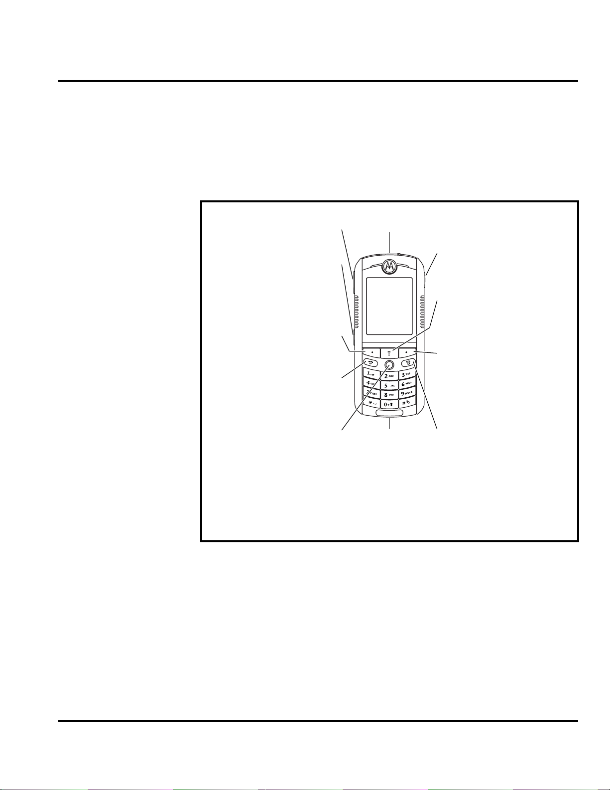
Controls, Indicators, and Input/Output (I/O) Connectors
The E398/E399 telephones’ controls are on the front of the device and on the
keyboard as shown in Figure 1. Indicator icons are displayed on the LCD (see
Figure 2).
Volume Key
Smart Key
Left Soft Key
Perform function
in lower left
display.
Send Key
Make & answer
calls.
5-Way Navigation
Joystick with
Center Select
Scroll through
menus, press in
to select items.
Headset Jack
Accessory
Connector
Camera Key
Activate camera
& take photos.
Menu Key
Right Soft Key
Perform function
in lower right
display.
Power & End Key
Turn phone
on/off, end calls,
exit menu
system.
Figure 1. Controls and Indicators
Menu Navigation
E398/E399 telephones have a simplified icon and GUI. See Figure 3 for the E398/
E399 menu structure. A scroll key allows you to move easily through menus.
Liquid Crystal Display (LCD)
The E398/E399 phone features a 176 x 220 color display offering 3 lines of text, 1
line of icons, and 1 line of prompts. The display provides constant graphical
representations of battery capacity and signal strength, as well as the real-time
clock.
6809480A37-O April 21, 2004 13
Page 14
General Operation E398/E399 GSM
Display animation makes the phone’s icon menu move smoothly as you scroll up
and down.
Whether a phone displays all indicators depends on the programming and services
➧
to which the user subscribes.
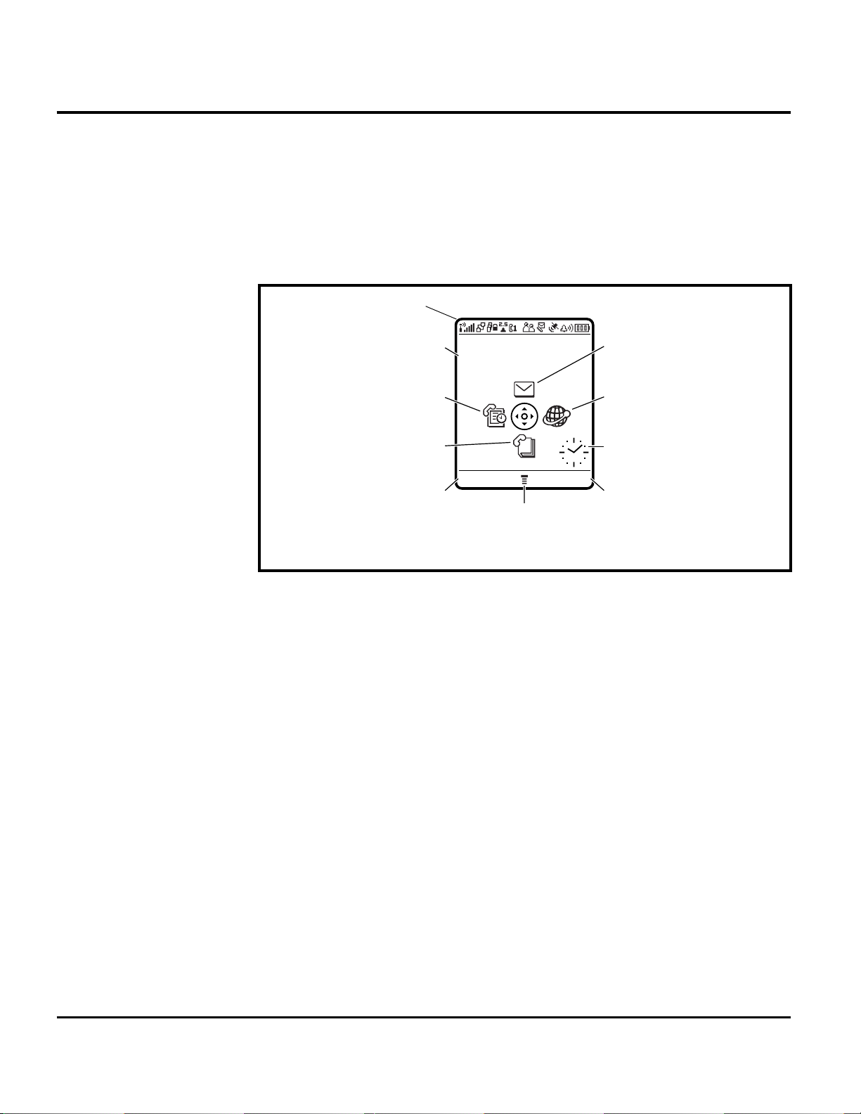
Figure 2 shows common icons displayed on the LCD.
Status Icons
Date
Service Provider
10/15/04
Recent Calls
Phonebook
STYLES SOUND
Left Soft Key
Label
Figure 2. E398/E399 Display Idle Screen
1. Status Icons show the status of your phone.
2. Real-Time Clock shows the current time.
3. Date shows the current date.
4. Soft Key Labels provide selectable options in screen display.
Menu Indicator
Messages
Browser
Clock
Right Soft Key
Label
14 April 21, 2004 6809480A37-O
Page 15

Level 1 and 2 Service Manual General Operation
D
User Interface Menu Structure
Figure 3 shows the E398/E399 telephone menu structure.
Main Menu
This is the standard main menu layout.
organization and feature names may vary on your
phone.
n
Phonebook
s
Recent Calls
e
Messages
É
Office Tools
Menu
Not all features may be available on your phone.
R
• Received Calls
• Dialed Calls
• Notepad
• Call Times
• Call Cost
•Data Times
•Data Volumes
• Create Message
• Message Inbox
•Voicemail
• Email Msgs
•Browser Msgs
• Info Services
• Quick Notes
•Outbox
• Drafts
• MMS Templates
• SIM Apps
• Calculator
• Datebook
• Shortcuts
•Alarm Clock
• Dialing Services
•Fixed Dial
• Service Dial
•Quick Dial
AFT
Q
Games & Apps
á
Web Access
•Browser
• Web Shortcuts
• Stored Pages
•History
•Go To URL
• Browser Setup
• Web Sessions
h
Multimedia
• Themes
•Camera
•Pictures
• Sounds
• MotoMixer
•Videos
ã
IM
w
Settings
(see next page)
See Settings Menu
K
Chat
Settings Menu
l
Personalize
• Rhythm Lights
• Home Screen
DRAFT
• Main Menu
•Skin
•Greeting
• Wallpaper
• Screen Saver
•Quick Dial
t
Ring Styles
•Style
• Style Detail
• Ring Lights
• Event Lights
L
Connection
• Bluetooth Link
•Sync
H
Call Forward
•Voice Calls
• Fax Calls
• Data Calls
•Cancel All
• Forward Status
U
In-Call Setup
• In-Call Timer
• Call Cost Setup
• My Caller ID
• Talk and Fax
• Answer Options
• Call Waiting
Z
Initial Setup
• Time and Date
• 1-Touch Dial
• Display Timeout
• Backlight
• TTY Setup
• Scroll
• Vibe Sync
• Language
• Brightness
•DTMF
• Master Reset
• Master Clear
m
Phone Status
•My Tel. Numbers
• Credit Info/Available
• Active Line
• Battery Meter
• Storage Devices
• Other Information
S
Headset
• Auto Answer
• Voice Dial
J
Car Settings
• Auto Answer
• Auto Handsfree
• Power-Off Delay
• Charger Time
j
Network
• New Network
• Network Setup
• Available Networks
• My Network List
• Service Tone
• Call Drop Tone
u
Security
• Phone Lock
• Lock Keypad
• Lock Application
• Fixed Dial
• Call Barring
• SIM PIN
•New Passwords
c
Java Settings
• Java App Loader
•Java System
• Delete All Apps
• App Vibration
• App Volume
• App Priority
• App Backlight
• Set Standby App
• DNS IP
Figure 3. E398/E399 Menu Structure
Alert Settings
Motorola E398/E399 phones incorporate the VibraCall® discreet vibrating alert
that helps to avoid disturbing others when a ringing phone is unacceptable.
Alerts can be set to ring only, vibrate only, vibrate then ring, or no ring or vibrate.
6809480A37-O April 21, 2004 15
Page 16

General Operation E398/E399 GSM
Battery Function
Battery Charge Indicator
The telephone displays a battery charge indicator icon in the idle screen to indicate
the battery charge level. The gauge shows 4 levels: 100%, 66%, 33%, and Low
Battery.
Battery Removal
Removing the battery causes the phone to shut down immediately and loose any
pending work. For example, (partially entered phonebook entries or outgoing
messages).
All batteries can cause property damage and/or bodily injury such as burns if a
conductive material such as jewelry, keys, or beaded chains touch exposed terminals.
E
The conductive material may complete an electrical circuit (short circuit) and
become quite hot. Exercise care when handling any charged battery, particularly
when placing it inside a pocket, purse, or other container with metal objects.
Operation
G
➧
If the battery is removed while receiving a message, the message is lost.
To ensure proper memory retention, turn the phone OFF before removing the
battery. Immediately replace the old battery with a fresh battery.
For detailed operating instructions, refer to the appropriate User’s Guide listed in
the Related Publications section toward the end of this manual.
16 April 21, 2004 6809480A37-O
Page 17

1 and 2
Level 1 and 2 Service Manual Tools and Test Equipment
6809480A37-O
E398/E399 GSM
Tools and Test Equipment
Table 1 lists the tools and test equipment used on E398/E399 telephones. Use either
the listed items or equivalents.
Table 1. General Test Equipment and Tools
Motorola
Part Number
See Table 6. Charger Used to charge battery and power phone.
0180386A82
6680388B67 Disassembly Tool, plastic with flat and pointed
6680388B01 Tweezers, plastic Used during assembly/disassembly.
RSX4043-A Torque Driver Used to remove and replace screws.
HP34401A
1. To order in North America, contact Motorola Aftermarket and Accessories Division (AAD) by phone at (800) 422-4210 or
FAX (800) 622-6210; Internationally, you can reach AAD by phone at (847) 538-8023 FAX (847) 576-3023.
2. Not available from Motorola. To order, contact Hewlett Packard at (800) 452-4844.
—
1
Antistatic Mat Kit (includes 66-80387A95 antistatic
mat, 66-80334B36 ground cord, and 42-80385A59
wrist band)
ends (manual opening tool)
Torque Driver Bit T-6 Plus, Apex 440-6IP Torx Plus
or equivalent
2
Digital Multimeter Used to measure battery voltage.
Description Application
Provides protection from damage to phone caused
by electrostatic discharge (ESD).
Used during assembly/disassembly.
Used with torque driver.
6809480A37-O April 21, 2004 17
Page 18

Disassembly E398/E399 GSM
Disassembly
This section describes how to disassemble a E398/E399 telephone. Tools and
equipment used are listed in Table 1.
Many of the integrated devices used in this phone are vulnerable to damage from
G
G
Removing and Replacing the Battery Cover
ESD. Ensure adequate static protection is in place when handling, shipping, and
servicing any internal components.
Avoid stressing the plastic in any way to avoid damage to either the plastic or
internal components.
1. Ensure the phone is turned off.
2. Press down on the battery cover latch on the bottom of the phone, and gently
slide the battery cover back away from the phone and lift it off (see Figure 4).
Battery Cover
Figure 4. Removing the Battery Cover
3. To replace, align the battery cover with the rear housing.
4. Place the battery cover on the rear housing and gently slide the battery cover
up into position until it snaps into place.
Slide Battery Cover Back
Latch
Location
18 April 21, 2004 6809480A37-O
Page 19

Level 1 and 2 Service Manual Disassembly
Removing and Replacing the Battery
1. Remove the battery cover as described in the procedures.
2. Lift the top end of the battery as indicated by the arrow in Figure 5.
3. Lift the battery up and out of the battery compartment.
Battery
E
Figure 5. Removing and Replacing the Battery
There is a danger of explosion if the Lithium-Ion battery is replaced incorrectly.
Replace only with the same type of battery or equivalent as recommended by the
battery manufacturer. Dispose of used batteries according to the manufacturer’s
instructions.
4. To replace, insert the bottom of the battery into the battery compartment with
contacts facing downward.
5. Press the top of the battery into the battery compartment.
6. Replace the battery cover as described in the procedures.
6809480A37-O April 21, 2004 19
Page 20

Disassembly E398/E399 GSM
Removing and Replacing the SIM Card
1. Remove the battery cover as described in the procedures.
2. Lift the top end of the battery as indicated by the arrow in Figure 6.
3. Lift the battery up and out of the battery compartment.
4. Lift up the SIM card holder and slide the SIM card out
SIM Card
Cut Corner
SIM Card
Holder
Figure 6. Removing and Replacing the SIM Card
5. To replace, slide the SIM card into the SIM card holder with the "cut" corner
located as shown and press the SIM card holder back down into the battery
compartment.
6. Insert the bottom of the battery into the battery compartment with contacts
facing downward.
7. Press the top of the battery into the battery compartment.
8. Replace the battery cover as described in the procedures.
20 April 21, 2004 6809480A37-O
Page 21

Level 1 and 2 Service Manual Disassembly
Removing and Replacing the Rear Housing
1. Remove the battery cover, battery, as described in the procedures.
2. Using a Torx
(see Figure 7).
3. Carefully separate the rear housing from the front housing by starting at the
top and lifting the rear housing up and away from the front housing to remove.
®
driver with a T-6 bit, remove the 6 screws from the rear housing
Lift Rear Housing
Up and Off Front
Housing
Rear Housing
Screw Locations
Figure 7. Removing and Replacing the Rear Housing
4. To replace, insert the bottom of the rear housing into the front housing and
gently press together.
5. Insert and torque the 6 screws to 2.6 in. pounds.
6. Replace the battery, and battery cover as described in the procedures.
Removing and Replacing the Transceiver PC Board
1. Remove the battery cover, battery, and rear housing as described in the
procedures.
G
This product contains static-sensitive devices. Use anti-static handling procedures
to prevent ESD and component damage.
2. Insert the flat end of the disassembly tool between the front housing and the
transceiver PC board as shown in Figure 8.
6809480A37-O April 21, 2004 21
Page 22

Disassembly E398/E399 GSM
3. At the top of the front housing, gently pry up and lift the transceiver PC board
out of the front housing.
Transceiver PC Board
Disassembly
Tool
Front
Housing
Figure 8. Removing and Replacing the Transceiver PC Board
4. To replace, insert the bottom of the circuit board into the bottom of the front
housing (display side down) and gently press the top of the circuit board into
the front housing.
5. Replace the rear housing, battery, and battery cover as described in the
procedures.
22 April 21, 2004 6809480A37-O
Page 23

Level 1 and 2 Service Manual Disassembly
Removing and Replacing the Keyboard
1. Remove the battery cover, battery, rear housing, and transceiver PC board, as
described in the procedures.
2. Using the disassembly tool, gently pry up the keyboard disconnecting it from
the transceiver PC board as shown in Figure 9.
Keyboard
Disassembly Tool
Figure 9. Removing and Replacing the Keyboard
3. To replace, align the keyboard connector of the keyboard with the keyboard
connector on the transceiver board and press it into place.
4. Replace the transceiver PC board, rear housing, battery, and battery cover as
described in the procedures.
6809480A37-O April 21, 2004 23
Page 24

Disassembly E398/E399 GSM
Removing and Replacing the Microphone
1. Remove the battery cover, battery, rear housing, transceiver PC board and the
keyboard, as described in the procedures.
2. Use the disassembly tool or plastic tweezers unplug the keyboard assembly
from the transceiver PC board.
3. Use plastic tweezers remove the microphone grommet.
4. Use the plastic tweezers to unplug the microphone from the transceiver board
as shown in Figure 10.
Plastic
Tweezers
Microphone
2 Microphone Pins
Figure 10. Removing and Replacing the Microphone
5. To replace, align the 2 microphone pins into the microphone contact holes.
Press the microphone firmly in place.
6. Replace the microphone grommet over the microphone.
7. Replace the keyboard assembly on the transceiver PC board and press firmly
in place.
8. Replace the transceiver PC board in the front housing, replace the rear
housing, battery, and battery cover as described in the procedures.
24 April 21, 2004 6809480A37-O
Page 25

Level 1 and 2 Service Manual Disassembly
Removing and Replacing the Speaker
1. Remove the battery cover, battery, rear housing, and circuit board as described
in the procedures.
2. Use the disassembly tool or plastic tweezers to release the speaker from the
front housing as shown in Figure 11. The speaker should come away easily.
Front Housing
Plastic
Tweezers
Speaker Contacts
Speaker
Figure 11. Removing and Replacing the Speaker
3. To replace, align the speaker with its socket with the speaker contacts facing
as shown.
4. Gently press the speaker into place.
5. Replace the transceiver PC board, rear housing, battery, and battery cover as
described in the procedures.
6809480A37-O April 21, 2004 25
Page 26

Disassembly E398/E399 GSM
Removing and Replacing the Keypad
1. Remove the battery cover, battery, rear housing, and transceiver PC board, as
described in the procedures.
2. Lift the keypad up from one corner as shown in Figure 12 and remove it from
the front housing.
Front Housing
Figure 12. Removing and Replacing the Keypad
3. To replace, align the keypad with the front housing and press it into place.
4. Replace the transceiver PC board, rear housing, battery, and battery cover as
described in the procedures.
Keypad
Plastic
Tweezers
26 April 21, 2004 6809480A37-O
Page 27

Level 1 and 2 Service Manual Disassembly
Removing and Replacing the Volume Switch Dome
1. Remove the battery cover, battery, rear housing, and transceiver PC board, as
described in the procedures.
2. Lift the switch domes out from the front housing as shown in Figure 13.
Plastic
Tweezers
Volume Switch
Dome
Front Housing
Figure 13. Removing and Replacing the Volume Switch Dome
3. To replace, insert the volume switch dome into the proper location in the front
housing.
4. Replace the transceiver PC board, rear housing, battery, and battery cover as
described in the procedures.
6809480A37-O April 21, 2004 27
Page 28

Disassembly E398/E399 GSM
b
r
Removing and Replacing the Display
1. Remove the battery cover, battery, rear housing, and transceiver PC board as
described in the procedures.
2. Using the disassembly tool, gently pry up the display and lift it up from the
transceiver PC board as shown in Figure 14.
3. Using the disassembly tool, gently pry up the display flex connector from the
transceiver PC board.
Disassembly Tool
Display
Disassem
Display
Flex Connecto
Disassembly Tool
Disassembly Tool
Disassembly
Tool
Figure 14. Removing and Replacing the Display
4. To replace, place the display flex connector on the transceiver PC board display
connector and press it into place.
5. Lay the display on the transceiver PC board and gently press it into place.
6. Replace the transceiver PC board, rear housing, battery, and battery cover as
described in the procedures.
28 April 21, 2004 6809480A37-O
Page 29

Level 1 and 2 Service Manual Disassembly
o
Removing and Replacing the MFT Chamber Assembly and Camera
1. Remove the battery cover, battery, rear housing, and transceiver PC board as
described in the procedures.
2. Disengage the two plastic MFT Chamber assembly side connectors from the
transceiver PC board and lift up the MFT Chamber assembly as shown in
Figure 15.
3. Using the disassembly tool, gently pry up the camera flex connector from the
transceiver PC board.
Disassembly Tool
MFT Chamber Assembly
assembly T
Camera
Disassembly Tool
Side Clips
Figure 15. Removing and Replacing the MFT Chamber Assembly
4. To replace, place the camera flex connector on the transceiver PC board camera
connector and press it into place.
5. Fold over the MFT Chamber assembly, aligning the camera with the camera
hole in the MFT Chamber and press into place engaging the two plastic side
clips on to the transceiver PC board.
6. Replace the transceiver PC board, rear housing, battery, and battery cover as
described in the procedures.
Disassembly Tool
Camera Flex Connector
Disassembly Tool
Disassembly Tool
6809480A37-O April 21, 2004 29
Page 30

Disassembly E398/E399 GSM
T
o
Removing and Replacing the Camera From MFT Chamber Assembly
1. Remove the battery cover, battery, rear housing, and transceiver PC board as
described in the procedures.
2. Disengage the two plastic MFT Chamber assembly side connectors from the
transceiver PC board and lift up the MFT Chamber assembly.
3. Using the disassembly tool, gently pry up the camera flex connector from the
transceiver PC board.
4. Using plastic tweezers, gently pry the connection between the camera flex and
the MFT Chamber assembly separating the adhesive.
Disassembly Tool
Disassembly Tool
MFT Chamber
Plastic Tweezers
sassembly To
Camera Flex
sembly
Camera
Figure 16. Removing and Replacing the Camera From the MFT Chamber
Assembly
5. To replace, press the MFT Chamber side of the camera flex connector onto the
MFT Chamber assembly.
6. Place the camera flex connector on the transceiver PC board camera connector
and press it into place.
7. Fold over the MFT Chamber assembly, aligning the camera with the camera
hole in the MFT Chamber and press into place engaging the two plastic side
connectors on to the transceiver PC board.
8. Replace the transceiver PC board, rear housing, battery, and battery cover as
described in the procedures.
30 April 21, 2004 6809480A37-O
Page 31

Level 1 and 2 Service Manual Subscriber Identity Module (SIM) and Identification
Label
Subscriber Identity Module (SIM) and Identification Label
SIM
A SIM is required to access the existing local GSM network, or remote networks
when traveling (if a roaming agreement has been made with the provider).
The SIM card contains:
• All the data necessary to access GSM services
• The ability to store user information such as phone numbers
• All information required by the network provider to provide access to the
network
Identification
Each Motorola GSM phone is labeled with a variety of identifying numbers. The
following information describes the current identifying labels.
Mechanical Serial Number (MSN)
The MSN is an individual unit identity number and remains with the unit throughout its life.
The MSN can be used to log and track a phone on Motorola's Service Center
Database.
The MSN is divided into 4 sections as shown in Figure 17.
MSN 10 Digits
3 Digits 1 Digit 2 Digits 4 Digits
APC DC DC SNR
Account Product Code
i.e. StarTAC Phone130
TM
Distribution Center
i.e. Easter Inch
Date Code: Year and
Month of Shipment
Unit's individual serial
number
000807a
Figure 17. MSN label breakdown
6809480A37-O April 21, 2004 31
Page 32

Subscriber Identity Module (SIM) and Identification Label E398/E399 GSM
International Mobile Station Equipment Identity (IMEI)
The International Mobile station Equipment Identity (IMEI) number is an
individual number unique to the PCB and is stored within the unit's memory.
The IMEI uniquely identifies an individual mobile station and thereby provides a
means for controlling access to GSM networks based on mobile station types or
individual units. The full IMEI structure is listed in Table 2.
Table 2. IMEI Number Breakdown
TAC Serial Number Check Digit
NNXXXX YY ZZZZZZ A
Where
TAC Type Allocation Code, formerly known as Type Approval Code
NN Reporting body identifier
XXXX Type Identifier
YY YY is set to 00 from 01/01/2003 until 31/03/2004
ZZZZZZ Individual unit serial number
A Phase 1 = 0.
Phase 2 = check digit defined as a function of all other IMEI digits
Other label number configurations present are:
• TRANSCEIVER NUMBER: Identifies the product type. Normally the SWF
number. (i.e. V100).
• PACKAGE NUMBER: Identifies the equipment type, mode, and language in
which the product is shipped.
32 April 21, 2004 6809480A37-O
Page 33

Level 1 and 2 Service Manual Troubleshooting
Troubleshooting
Manual Test Mode
Motorola E398/E399 telephones are equipped with a manual test mode capability.
This allows service personnel to verify functionality and perform fault isolation by
entering keypad commands.
To enter the manual test command mode, a GSM/DCS test SIM must be used.
1. Turn the phone OFF.
2. Remove the battery as described in the procedures.
3. Remove the customer’s SIM card from the phone as described in the
procedures.
4. Insert the test SIM into the SIM slot.
5. Replace the battery as described in the procedures.
6. Turn the phone ON.
Manual Test Mode Commands
Table 3. Manual Test Commands
Key Sequence Test Function/Name Remarks
<Menu>048263* Enter manual test mode
“End” Key Exit manual test mode
54* Suspend Required for all Test Mode Operations
0*0*0 Select tone 0
0*0*1 Select tone 1
0*0*2 Select tone 2
0*0*3 Select tone 3
0*0*4 Select tone 4
0*0*5 Select tone 5
0*0*6 Select tone 6
0*0*7 Select tone 7
0*0*8 Select tone 8
0*0*9 Select tone 9
0*1*X Disable tone X
3*0*1 Enable vibrator
3*0*0 Disable vibrator
5*0*0 Set audio level 0
5*0*1 Set audio level 1
5*0*2 Set audio level 2
5*0*3 Set audio level 3
5*0*4 Set audio level 4
5*0*5 Set audio level 5
5*0*6 Set audio level 6
5*0*7 Set audio level 7
6809480A37-O April 21, 2004 33
Page 34

Troubleshooting E398/E399 GSM
Table 3. Manual Test Commands (Continued)
Key Sequence Test Function/Name Remarks
5*0*8 Set audio level 8
5*0*9 Set audio level 9
5*0*10 Set audio level 10
5*0*11 Set audio level 11
5*0*12 Set audio level 12
5*0*13 Set audio level 13
5*0*14 Set audio level 14
5*0*15 Set audio level 15
6*2*2*0*0 Set Audio Path. Int Mic, IntSpk, RX unmute, TX unmute
6*4*6*0*0 Set Audio Path. Boom Mic, Boom Spk, RX unmute, TX unmute
10*0*3 Set band GSM 900
10*0*4 Set band DCS 1800
10*0*5 Set band PCS 1900
10*0*6 Set dual band GSM 900/1800
10*1*0 Read band 3= GSM 4= DCS 5= PCS 6 =GSM/DCS
18*0 Initialize non-volatile memory (Master Reset)
18*1 Initialize non-volatile memory (Master Clear)
55*2*001 Test Display. All pixels ON
55*2*000 Test Display. All pixels OFF
55*2*002 Test Display. Checkerboard pattern A
55*2*003 Test Display. Checkerboard pattern B
55*2*004 Test Display. Border pixels ON
*#06# IMEI Check No Test Mode Required
Phone Set up -->
Phone Status -->
Other
Information
Flex Version/Technology/S-W Version/Readiness Status No Test Mode Required
34 April 21, 2004 6809480A37-O
Page 35

Level 1 and 2 Service Manual Troubleshooting
Troubleshooting Chart
Table 4. E389/E399 Telephone: Level 1 and 2 Troubleshooting Chart
Symptom Probable Cause Verification and Remedy
1. Telephone will not turn on or stay on. a) Battery either discharged or
2. Telephone exhibits poor reception or
erratic operation such as calls frequently
dropping or weak or distorted audio.
3. Display is erratic, or provides partial or
no display.
4. Incoming call alert transducer audio
distorted or volume is too low.
b) Faulty transceiver board assembly. Replace the transceiver board assembly (refer
5. Telephone transmit audio is weak.
(usually indicated by called parties
complaining of difficulty in hearing voice).
defective.
b) Battery terminals open or
misaligned.
c) Transceiver board defective. Remove the transceiver board assembly.
a) Antenna defective. Check connection between the antenna and the
b) Transceiver board defective. Replace the transceiver board (refer to 1c).
a) Transceiver board connections
faulty.
b) Display assembly defective. Temporarily replace the display assembly with a
c) Transceiver board assembly
defective.
a) Speaker assembly defective Temporarily replace the speaker assembly with
a) Microphone defective. Replace the microphone as described in the
Measure battery voltage across a 50 ohm
(>1 Watt) load. If battery voltage is <3.25 Vdc,
recharge the battery using the appropriate
battery charger. If battery will not recharge,
replace the battery. If battery is not at fault,
proceed to b.
Visually inspect battery terminals on both the
battery and the telephone. Realign and, if
necessary, either replace the battery or refer to
a Level 3 Service Center for battery connector
replacement. If battery terminals are not at fault,
proceed to c.
Substitute a known good transceiver board and
temporarily reassemble the phone. Press the
Power/End key; if phone turns on and stays on,
disconnect the dc power source and reassemble
the phone with the new transceiver board. Verify
that the fault has been cleared.
transceiver board. If the connection is OK,
substitute a known good antenna. If the fault is
still present, proceed to b.
Verify that the fault has been cleared and
reassemble the phone with the new transceiver
board.
Check general condition of flexible printed cable
(flex). If the flex is good, check that the flex
connector is fully seated. If not, check connector
to transceiver board connections. If faulty
connector, replace the transceiver board
assembly. If connector is not at fault, proceed to
b.
known good assembly. If fault has been cleared,
reassemble with the new display assembly. If
fault not cleared, proceed to c.
Replace the transceiver board assembly (refer
to 1c). Verify that the fault has been cleared and
reassemble the unit with the new transceiver
board assembly.
a known good assembly. If fault has been
cleared, reassemble with the new speaker
assembly. If fault not cleared, proceed to
to 1c). Verify that the fault has been cleared and
reassemble the unit with the new transceiver
board assembly.
procedures. If fault is not cleared, proceed to b.
6809480A37-O April 21, 2004 35
Page 36

Troubleshooting E398/E399 GSM
Table 4. E389/E399 Telephone: Level 1 and 2 Troubleshooting Chart (Continued)
Symptom Probable Cause Verification and Remedy
b) Transceiver board defective. Replace the transceiver board (refer to 1c).
6. Receive audio from earpiece speaker is
weak or distorted.
7. Vibrator feature not functioning. a) Speaker Module defective Replace Speaker Module. If the fault has not
8. Internal Charger not working. Faulty charger circuit on transceiver
9. No or weak audio when using headset. a) Headset plug not pushed in fully. Ensure the headset plug is fully seated in the
a) Connections to or from transceiver
board defective.
b) Earpiece speaker defective. Temporarily replace the speaker with a known
c) Transceiver board defective. Replace the transceiver board (refer to 1c).
b) Transceiver board defective. Replace the transceiver board (refer to 1c).
board.
b) Faulty jack on transceiver board. Replace the transceiver board (refer to 1c).
Verify that the fault has been cleared and
reassemble the phone with the new transceiver
board.
Check connection from the earpiece to the
transceiver board. If connection is not at fault,
proceed to b.
good speaker. Ensure good connection. Place a
call and verify improvement in earpiece audio. If
fault is cleared, reassemble the phone with the
good transceiver board. If fault is not cleared,
proceed to c.
Verify that the fault has been cleared and
reassemble the phone with the new transceiver
board.
been cleared, proceed to b.
Verify that the fault has been cleared and
reassemble the phone with the new transceiver
board.
Test a selection of batteries in the rear pocket of
the desktop charger. Check LED display for the
charging indications. If these are charging
properly, then the internal charger is at fault.
Replace the transceiver board assembly (refer
to 1c). Verify that the fault has been cleared and
reassemble the phone with the new transceiver
board assembly.
jack.
Verify that the fault has been cleared and
reassemble the phone with the new transceiver
board.
36 April 21, 2004 6809480A37-O
Page 37

Level 1 and 2 Service Manual Troubleshooting
Programming: Software Upgrade and Flexing
Contact your local technical support engineer for information about equipment and
procedures for flashing and flexing.
6809480A37-O April 21, 2004 37
Page 38

Part Numbers E398/E399 GSM
Part Numbers
The following section provides a reference for the parts associated with
E398/E399 telephones.
Exploded View Diagram
Figure 18. E389/E399 Exploded View Diagram
38 April 21, 2004 6809480A37-O
Page 39

Level 1 and 2 Service Manual Part Numbers
Exploded View Parts List
Table 5. Exploded View Parts List
Item
Number
1 1589653N01 Battery Door Assembly 13 4089581N01 Mylar
2 Battery 14 Keyboard Assembly
3 1389586N01 Rear Escutcheon 15 72D89638N01 Display Assembly
4 0589607N01 Conductive Camera Grommet 16 3889517N01 Keypad
5 Torx Screws (6) 17 4089522N01 Single Switch Dome
6 0189652N01 Rear Housing Assembly 18 4089522N01 Single Switch Dome
7 0189619N01 Camera Assembly 19 5089574N01 Speaker
8 158960N01 MFT Chamber Assembly 20 4089521N01 Volume Switch Domes
9 6087603L01 RTC Battery 21 1589601N01 Front Housing Assembly
10 5087974K02 Microphone 22 0589579N01 Headset Jack Grommet
11 ?? 23 6189597N01 Lens
12 0589598N01 Microphone Grommet 24 1389573N01 Front Escutcheon
Motorola Part
Number
Description
Item
Number
Motorola Part
Number
Description
E
There is a danger of explosion if the Lithium ion battery pack is replaced incorrectly.
Replace only with the same type of battery or equivalent as recommended by the
battery manufacturer. Dispose of used batteries according to the manufacturer’s
instructions.
To order parts please use the following link:
https://accesssecure.mot.com
(Password is required)
6809480A37-O April 21, 2004 39
Page 40

Part Numbers E398/E399 GSM
Accessories
Table 6. List of Accessories
Description Part Number
Power Supply, US & Taiwan SPN5037B
Travel Charger, Euro SPN5038
Travel Charger, UK/Hong Kong SPN5039
Travel Charger, PRY SPN5040
Travel Charger, Australia SPN5046
Travel Charger, India SPN5046
Headset, Black CHYN4516
Related Publications
Publication Title Part Number (Kit Number)
Motorola E398 User Guide, English 6887301Z52
Note: Kit numbers are not all inclusive and may change without notice.
40 April 21, 2004 6809480A37-O
Page 41

1 and 2
Level 1 and 2 Service Manual Index
6809480A37-O
E398/E399 GSM
Index
A
alert settings 15
B
battery
charge indicator 16
function 16
battery, removing and replacing 18, 19
C
caller ID 11
Canadian Interference-Causing Equipment regulations 5
copyrights
computer software 6
D
disassembly 18
E
exploded view diagram 38
exploded view parts list 39
F
FCC rules 5
features
caller ID 11
front speaker, removing and replacing 25
I
identification
product 5
identification, labels 31
Introduction 5
K
keypad, removing and replacing 26
manual test mode 33
manual test mode commands 33
menu structure 15
microphone, removing and replacing 24
N
names
product 5
O
operation 13
alert settings 15
battery 16
controls, indicators, and I/O connectors 13
icons 14
alarm 14
battery charge indicator 14
battery level indicator 14
digital/analog indicator 14
real-time clock 14
ring style indicator 14
roam 14
signal strength 14
LCD 13
menu navigation 13
menu structure 15
operations
icons
soft keys 14
overview, product 11
P
parts
exploded view diagram 38
exploded view parts list 39
product
identification 5
names 5
product overview 11
features 11
publications, related 40
L
LCD 13
liquid crystal display (LCD) 13
M
6809480A37-O April 21, 2004 39
R
Rear housing cover, removing and replacing 18
regulatory agency compliance 5
related publications 40
Removing
transceiver PC board 21
Page 42

Index E398/E399 GSM
removing
battery 16, 18, 19
speaker 25
keyboard 23
keypad 26
microphone 24
rear housing cover 21
sim card 20
transceiver PC board 21
replacement parts
ordering 8
replacing
battery 18, 19
speaker 25
keyboard 23
microphone 24
rear housing cover 21
sim card 20
transceiver PC board 21
S
service manual
about 6
audience 6
conventions 7
scope 6
service policy 7
customer support 7
out of box failure 7
product support 7
shut down
upon battery removal 16
specifications 9
support
customer 7
product 7
T
test equipment 17
tools, disassembly 17
transceiver PC board, removing and replacing 21
troubleshooting 33
manual test mode 33
manual test mode commands 33
troubleshooting chart 35
W
warranty service 7
40 April 21, 2004 6809480A37-O
Page 43

Page 44

MOTOROLA, the Stylized M Logo, and all other trademarks indicated as such herein are trademarks of Motorola, Inc.
Truesync is a trademark of Starfish Software, Inc.
® Reg. U.S. Pat. & Tm. Off.
© 2004 Motorola, Inc.
All rights reserved.
Personal Communications Sector,
789 International Parkway, Room S2C
Sunrise, FL 33325-6220.
@6809480A37@
6809480A37-O
 Loading...