

Page 1
Level 1 and 2 Service Manual
E1000
Wireless Telephone
2nd Draft
E1000: GSM 900/1800/1900 and WCDMA 2100 MHz
Motorola Confidential Proprietary
Page 2

Page 3

1 and 2
E1000
Level 1 and 2 Service Manual Contents
6809490A73
Contents
Introduction . . . . . . . . . . . . . . . . . . . . . . . . . . . . . . . . . . . . . . . . . . . . . . . . . . . . . . . . . . . . . . . . . . . . . . . . . . . . . . . . . 5
Product Identification . . . . . . . . . . . . . . . . . . . . . . . . . . . . . . . . . . . . . . . . . . . . . . . . . . . . . . . . . . . . . . . . . . . 5
Product Names . . . . . . . . . . . . . . . . . . . . . . . . . . . . . . . . . . . . . . . . . . . . . . . . . . . . . . . . . . . . . . . . . . . . . . . . 5
Product Changes . . . . . . . . . . . . . . . . . . . . . . . . . . . . . . . . . . . . . . . . . . . . . . . . . . . . . . . . . . . . . . . . . . . . . . . 5
Computer Program Copyrights . . . . . . . . . . . . . . . . . . . . . . . . . . . . . . . . . . . . . . . . . . . . . . . . . . . . . . . . . . . 5
About This Service Manual . . . . . . . . . . . . . . . . . . . . . . . . . . . . . . . . . . . . . . . . . . . . . . . . . . . . . . . . . . . . . . 6
Warranty Service Policy . . . . . . . . . . . . . . . . . . . . . . . . . . . . . . . . . . . . . . . . . . . . . . . . . . . . . . . . . . . . . . . . . 7
Parts Replacement . . . . . . . . . . . . . . . . . . . . . . . . . . . . . . . . . . . . . . . . . . . . . . . . . . . . . . . . . . . . . . . . . . . . . 7
Specifications . . . . . . . . . . . . . . . . . . . . . . . . . . . . . . . . . . . . . . . . . . . . . . . . . . . . . . . . . . . . . . . . . . . . . . . . . . . . . . . 8
Product Overview . . . . . . . . . . . . . . . . . . . . . . . . . . . . . . . . . . . . . . . . . . . . . . . . . . . . . . . . . . . . . . . . . . . . . . . . . . . 10
E1000: Video Camera and Location Solutions . . . . . . . . . . . . . . . . . . . . . . . . . . . . . . . . . . . . . . . . . . . . . . 10
General Operation . . . . . . . . . . . . . . . . . . . . . . . . . . . . . . . . . . . . . . . . . . . . . . . . . . . . . . . . . . . . . . . . . . . . . . . . . . . 12
Controls, Indicators, and Input/Output (I/O) Connectors . . . . . . . . . . . . . . . . . . . . . . . . . . . . . . . . . . . . . 12
User Interface Menu Structure . . . . . . . . . . . . . . . . . . . . . . . . . . . . . . . . . . . . . . . . . . . . . . . . . . . . . . . . . . 15
Battery Function . . . . . . . . . . . . . . . . . . . . . . . . . . . . . . . . . . . . . . . . . . . . . . . . . . . . . . . . . . . . . . . . . . . . . . 15
Operation . . . . . . . . . . . . . . . . . . . . . . . . . . . . . . . . . . . . . . . . . . . . . . . . . . . . . . . . . . . . . . . . . . . . . . . . . . . . 16
Tools and Test Equipment . . . . . . . . . . . . . . . . . . . . . . . . . . . . . . . . . . . . . . . . . . . . . . . . . . . . . . . . . . . . . . . . . . . . 17
Disassembly . . . . . . . . . . . . . . . . . . . . . . . . . . . . . . . . . . . . . . . . . . . . . . . . . . . . . . . . . . . . . . . . . . . . . . . . . . . . . . . . 18
Removing and Replacing the Battery Door . . . . . . . . . . . . . . . . . . . . . . . . . . . . . . . . . . . . . . . . . . . . . . . . . 18
Removing and Replacing the Battery . . . . . . . . . . . . . . . . . . . . . . . . . . . . . . . . . . . . . . . . . . . . . . . . . . . . . 19
Removing and Replacing the SIM Card . . . . . . . . . . . . . . . . . . . . . . . . . . . . . . . . . . . . . . . . . . . . . . . . . . . 20
Removing and Replacing the Front Housing . . . . . . . . . . . . . . . . . . . . . . . . . . . . . . . . . . . . . . . . . . . . . . . . 21
Removing and Replacing the Rear Housing . . . . . . . . . . . . . . . . . . . . . . . . . . . . . . . . . . . . . . . . . . . . . . . . 22
Removing and Replacing the Battery Shield . . . . . . . . . . . . . . . . . . . . . . . . . . . . . . . . . . . . . . . . . . . . . . . . 23
Removing and Replacing the Key Board . . . . . . . . . . . . . . . . . . . . . . . . . . . . . . . . . . . . . . . . . . . . . . . . . . . 24
Removing and Replacing the Keypad . . . . . . . . . . . . . . . . . . . . . . . . . . . . . . . . . . . . . . . . . . . . . . . . . . . . . 25
Removing and Replacing the Speaker Assembly . . . . . . . . . . . . . . . . . . . . . . . . . . . . . . . . . . . . . . . . . . . . 26
Removing and Replacing the Joystick Assembly . . . . . . . . . . . . . . . . . . . . . . . . . . . . . . . . . . . . . . . . . . . . 27
Removing and Replacing the Display Assembly . . . . . . . . . . . . . . . . . . . . . . . . . . . . . . . . . . . . . . . . . . . . . 29
Removing and Replacing the Camera . . . . . . . . . . . . . . . . . . . . . . . . . . . . . . . . . . . . . . . . . . . . . . . . . . . . . 31
UMTS Subscriber Identity Module (USIM) Identification Label . . . . . . . . . . . . . . . . . . . . . . . . . . . . . . . . . . . . . . . 32
USIM . . . . . . . . . . . . . . . . . . . . . . . . . . . . . . . . . . . . . . . . . . . . . . . . . . . . . . . . . . . . . . . . . . . . . . . . . . . . . . . 32
Identification . . . . . . . . . . . . . . . . . . . . . . . . . . . . . . . . . . . . . . . . . . . . . . . . . . . . . . . . . . . . . . . . . . . . . . . . . 32
Troubleshooting . . . . . . . . . . . . . . . . . . . . . . . . . . . . . . . . . . . . . . . . . . . . . . . . . . . . . . . . . . . . . . . . . . . . . . . . . . . . 34
Troubleshooting Chart . . . . . . . . . . . . . . . . . . . . . . . . . . . . . . . . . . . . . . . . . . . . . . . . . . . . . . . . . . . . . . . . . 34
Programming: Software Upgrade and Flexing . . . . . . . . . . . . . . . . . . . . . . . . . . . . . . . . . . . . . . . . . . . . . . 35
Part Number Charts . . . . . . . . . . . . . . . . . . . . . . . . . . . . . . . . . . . . . . . . . . . . . . . . . . . . . . . . . . . . . . . . . . . . . . . . . . 36
Related Publications . . . . . . . . . . . . . . . . . . . . . . . . . . . . . . . . . . . . . . . . . . . . . . . . . . . . . . . . . . . . . . . . . . . 36
Exploded View Parts List . . . . . . . . . . . . . . . . . . . . . . . . . . . . . . . . . . . . . . . . . . . . . . . . . . . . . . . . . . . . . . 36
Exploded View Diagram . . . . . . . . . . . . . . . . . . . . . . . . . . . . . . . . . . . . . . . . . . . . . . . . . . . . . . . . . . . . . . . . 37
6809490A73 October 4, 2004 3
Motorola Confidential Proprietary
Page 4

Contents E1000
4 October 4, 2004 6809490A73
Motorola Confidential Proprietary
Page 5

1 and 2
E1000
Level 1 and 2 Service Manual Introduction
6809490A73-O
Introduction
Motorola® Inc. maintains a worldwide organization that is dedicated to provide
responsive, full-service customer support. Motorola products are serviced by an
international network of company-operated product care centers as well as
authorized independent service firms.
Available on a contract basis, Motorola Inc. offers comprehensive maintenance and
installation programs which enable customers to meet requirements for reliable,
continuous communications.
To learn more about the wide range of Motorola service programs, contact your local
Motorola products representative or the nearest Customer Service Manager.
Product Identification
Motorola products are identified by the model number on the housing. Use the entire
model number when inquiring about the product. Numbers are also assigned to
chassis and kits. Use these numbers when requesting information or ordering
replacement parts.
Product Names
Product names are listed on the front cover. Product names are subject to change
without notice. Some product names, as well as some frequency bands, are available
only in certain markets.
Product Changes
When electrical, mechanical, or production changes are incorporated into Motorola
products, a revision letter is assigned to the chassis or kit affected, for example:
-A, -B, or -C, and so on.
The chassis or kit number, complete with revision number, is imprinted during
production. The revision letter is an integral part of the chassis or kit number and
is also listed on schematic diagrams and printed-circuit board layouts.
Computer Program Copyrights
The Motorola products described in this manual may include Motorola computer
programs stored in semiconductor memories or other media that are copyrighted
with all rights reserved worldwide to Motorola. Laws in the United States and other
countries preserve for Motorola, Inc. certain exclusive rights to the copyrighted
computer programs, including the exclusive right to copy, reproduce, modify,
decompile, disassemble, and reverse-engineer the Motorola computer programs in
any manner or form without Motorola's prior written consent. Furthermore, the
purchase of Motorola products shall not be deemed to grant either directly or by
implication, estoppel, or otherwise, any license or rights under the copyrights,
patents, or patent applications of Motorola, except for a nonexclusive license to use
the Motorola product and the Motorola computer programs with the Motorola
product.
6809490A73-O October 4, 2004 5
Page 6

Introduction E1000
About This Service Manual
Using this service manual and the suggestions contained in it assures proper
installation, operation, and maintenance of E1000 telephones. Refer questions
about this manual to the nearest Customer Service Manager.
Audience
This document aids service personnel in testing and repairing E1000 telephones.
Service personnel should be familiar with electronic assembly, testing, and
troubleshooting methods, and with the operation and use of associated test
equipment.
Use of this document assures proper installation, operation, and maintenance of
Motorola products and equipment. It contains all service information required for
the equipment described and is current as of the printing date.
Scope
This document provides basic information, procedures, and processes for repairing
the phones at Level 1 and 2 service centers including:
•Unit swap out
• Repairing of mechanical faults
• Basic modular troubleshooting
•Testing and verification of unit functionality
• Initiate warranty claims and send faulty modules to Level 3 or 4 repair
centers.
Conventions
Special characters and typefaces, listed and described below, are used in this
publication to emphasize certain types of information.
➧
G
E
Note: Emphasizes additional information pertinent to the subject
matter.
Caution: Emphasizes information about actions which may result in
equipment damage.
Warning: Emphasizes information about actions which may result
in personal injury.
Information from a screen is shown in text as similar as possible to what
appears in the display. For example, ALERTS.
Information that you need to type is printed in boldface type
6 October 4, 2004 6809490A73-O
Page 7

Level 1 and 2 Service Manual Introduction
Warranty Service Policy
The product is sold with the standard 12-month warranty terms and conditions.
Accidental damage, misuse, and extended warranties offered by retailers are not
supported under warranty. Non warranty repairs are available at agreed fixed
repair prices.
Out-of-Box Failure Policy
The standard out of box failure criteria applies. Customer phones that fail very
early on after the date of sale, are to be returned to Manufacturing for root cause
analysis, to guard against epidemic criteria. Manufacturing to bear the costs of early
life failure.
Product Support
Customer’s original phones will be repaired but not refurbished as standard.
Appointed Motorola Service Hubs will perform warranty and non-warranty field
service for level 2 (assemblies) and level 3 (limited PCB component). The Motorola
High Technology Centers will perform level 4 (full component) repairs.
Parts Replacement
Customer Support
Customer support is available through dedicated Call Centers and in-country help
desks. Product Service training should be arranged through the local Motorola
Support Center.
When ordering replacement parts or equipment, include the Motorola part number
and description used in the service manual.
When the Motorola part number of a component is not known, use the product model
number or other related major assembly along with a description of the related
major assembly and of the component in question.
Order replacement parts, test equipment, and manuals from AAD.
U.S.A. Outside U.S.A.
Phone: 800-422-4210 Phone: 847-538-8023
FAX: 800-622-6210 FAX: 847-576-3023
To order parts online, visit:
https://servicelink3.motorola.com.
(contact the EMEA Service Parts Group for the password required)
You can contact the EMEA Service Parts Group at:
+49 461 803 1638.
6809490A73-O October 4, 2004 7
Page 8
Specifications E1000
Specifications
Table 1. Specifications
General Function Specification
Frequency Range GSM 850
(Model A845 Only)
Frequency Range EGSM TX: 876 - 915 MHz
Frequency Range DCS TX: 1710 to 1785 MHz
Frequency Range PCS TX: 1850 to 1910 MHz
TX: 824.2 - 848.8 MHz
Frequency (MHz) = 824.2 + (0.2 n-128)where: 128 ≤ n ≤ 251
RX: 869.2-893.8 MHz
Frequency (MHz) = 869.2 + (0.2 (n - 128)) where: 128 ≤ n ≤ 251
Frequency (MHz) = 890 + (0.2 × n) where: 0 ≤ n ≤ 124
Frequency (MHz) = 890 + (0.2 × (n – 1024)) where: 955 ≤ n ≤ 1023
RX: 921 – 960 MHz
Frequency (MHz) = 935 + (0.2 × n) where: 0 ≤ n ≤ 124
Frequency (MHz) = 935 + (0.2 × (n – 1024)) where: 955 ≤ n ≤ 1023
Frequency (MHz) = 1710 + (0.2 × (n – 511)) where: 512 ≤ n ≤ 885
RX: 1805.2 to 1879.8 MHZ
Frequency (MHz) = 1805 + (0.2 × (n – 511)) where: 512 ≤ n ≤ 885
Frequency (MHz) = 1850 + (0.2 × (n – 511)) where: 512 ≤ n ≤ 810
RX: 1930 to 1990 MHZ
Frequency (MHz) = 1930 + (0.2 × (n – 511)) where: 512 ≤ n ≤ 810
Frequency Range UMTS TX: 1920 to 1980 MHz
Frequency Range UMTS
Band II
(Model A845 only)
Channel Spacing 200 kHz (GSM, DCS, PCS), 5MHz UMTS
Channels 174 EGSM, 374 DCS, 274 PCS carriers with 8 ch. Per carrier, 12
Duplex Spacing 45 MHz GSM, 95 MHz DCS, 80 MHz PCS, 80 MHz UMTS
Modulation GMSK AT BT = 0.3 (GSM, DCS, PCS), QPSK (UMTS)
Transmitter Phase Accuracy 5 degrees RMS, 20 degrees peak
Frequency Error +
Input/Output Impedance 50 ohms (nominal)
Nominal Operating Voltage 3.6 Vdc +
Dimensions (Volume) 135 x 53 x 24.2 (mm), 5.3 x 2.1 x 0.95 (in)
Volume 138 cc
Weight 157 g, 5.54 oz
Frequency (MHz) = UARFCN
UARFCN1 in increments of 25
RX: 2110 to 2170 MHz
Frequency (MHz) = UARFCN1 ÷ 5, where: 10562 < UARFCN1 <
10838
UARFCN1 in increments of 25
TX: 1850 -1910 MHz
Frequency (MHz) = UARFCN1 ÷ 5, where: 9262 < UARFCN1 <
9538
Additional channels: 1852.5, 1857.5, 1862.5, 1867.5, 1872.5,
1877.5, 1882.5, 1887.5, 1892.5, 1897.5, 1902.5, 1907.5 MHz
RX: 1930 -1990 MHz
Frequency (MHz) = UARFCN
Additional channels: 1932.5, 1937.5, 1942.5, 1947.5, 1952.5,
1957.5, 1962.5, 1967.5, 1972.5, 1977.5, 1982.5, 1987.5 MHz
UMTS maximum
0.1ppm
10% (battery)
+4.4 Vdc +10% (external connector)
1
÷ 5, where: 9612 < UARFCN1 < 9888
1
÷ 5, where: 9662 < UARFCN1 < 9938
8 October 4, 2004 6809490A73-O
Page 9
Level 1 and 2 Service Manual Specifications
Table 1. Specifications
General Function Specification
Display TFT active full-color display (64k colors)
Battery Life (800mAh)
Nominal Temperature Range -20º C to +50º C
1
UTRA Absolute Radio Frequency Channel Number (UARFCN)
2
All talk time and standby times are approximate and depend on network
2
176 x 220 pixel EL Backlighting
5 row x 15 character: SMS & Phonebook
GSM: Up to 460 min (Talk Time), up to 300 hours (Standby)
WCDMA: Up to 140 min (Talk Time), up to 300 hours (Standby)
configuration, signal strength, and features selected
Table 2. GSM System
General Function Specification
Speech Coding Type Regular Pulse excitation / linear predictive coding with long
Bit Rate 13.0 kbps
RF Power Output 32 dBm nominal GSM, 30 dBm nominal DCS / PCS
Receive Sensitivity -107 dBm GSM, -105 dBm DCS / PCS
RX Bit Error Rate < 2%
term prediction (RPE LPC with LTP)
Table 3. UMTS System
General Function Specification
Speech Coding Type Adaptive Multirate (AMR)
RF Power Output 21 dBm
Error Vector Magnitude < 15%
PN9 Bit Error Rate (VER) 0.1% @12.2k, 0.1% @64k, 0.1% @384k
ACLR -33 dBm @+
5 MHz, -43 dBm @+10 MHz
6809490A73-O October 4, 2004 9
Page 10

Product Overview E1000
Product Overview
The E1000 is a 3G (3rd generation) devices that will deliver on the “promise” of 3G
by providing high speed network access and rich multimedia content all in a
superior voice-centric unit. A video camera and Assisted GPS provide additional
value by offering unique business and entertainment solutions.
The mechanical architecture features a 320 x 240 pixel, 0.198mm pitch TFT active
color display, a built-in speaker phone, and a removable Li-Polymer battery. The
architecture enables full postponement of the front housing and battery door cover
by allowing the transceiver brick assembly, keypad, display, microphone, and
earpiece speaker to be fully assembled and retained within the rear housing chassis.
Front covers may then be snapped in at distribution based on specific orders. Front
housing branding is accomplished through thermal transfer decals.
As a 3G product, the E1000 complies with all key specifications as defined by the
3GPP. Key product features are:
• UMTS: WCDMA 2100, GSM 900/1800 and 1900-MHz Tri-band technology,
•GPRS High speed packet data (64kbps UL, 384 kbps DL)
• 320 x 240 TFT Active Color, 260K colors
• 256MB Integrated Flash Memory
• Integrated Bluetooth
• MP3 Player
• Enhanced Multimedia Capability (Audio/Video, Games, MMS)
• Unique 5-way Navigation Key
• New graphical user interface
• Enhanced internet browser (XHTML)
• Full Personal Information Manager (PIM) with SyncML Synchronization (OTA,
Desktop)
• Integrated Camera 1.2 Mega pixel and GPS
• Voice Recognition Driven Dialing and Menu Shortcuts
• Voice Note Voice Recorder
• Polyphonic Speakerphone
• Programmable (J2ME)
•iTAP™ Predictive Text Entry
• Integrated Stereo Headset Jack
Note: The listed features may be Network, subscription, or service provider
dependent. Not available in all areas.
E1000: Video Camera and Location Solutions
Video Camera Features:
• JPEG Image Capture @ VGA Resolution
• MPEG4 Video Capture @ QCIF Resolution
• Streaming Video
• Tightly Coupled, Ergonomic Design
• Initial User Applications:
• Sending captured Video Clips and Pictures through MMS, Email, or
Internet channels
• Simultaneous Voice/Data – Take a picture or video clip and send while
you’re on the phone
10 October 4, 2004 6809490A73-O
Page 11

Level 1 and 2 Service Manual Product Overview
• Future Capabilities:
• Video Conferencing (2-Way Video Telephony)
Location (AGPS) Applications:
• Get to specific location, with appropriate choices of destinations and routes and
guidance to destination
• Identify local places of interest for hotels, taxi companies, restaurants,
theatres, sightseeing, and shopping
• Receive information through alerts or display on map ahead of traffic
congestion.
• Receive roadside assistance, with rescue service network and location
information from the cellular network used to complement any information the
pedestrian/driver is able to separately give.
• E911 Services: When roaming on a 2-2.5G GSM E-OTD-enabled network the
mobile phone will respond to a request for location when making an emergency
call.
• Push, Tracking & B2B Applications such as corporate tracking, routing, fleet
management, and Buddy tracking (alert)
6809490A73-O October 4, 2004 11
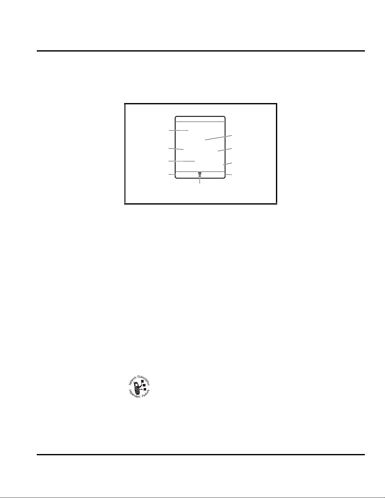
Page 12
General Operation E1000
General Operation
Controls, Indicators, and Input/Output (I/O) Connectors
The E1000 telephone controls are located on the front of the phone, and on the
keyboard as shown. Indicators, in the form of icons, are displayed on the LCD (see
“Color Display” on page 13).
Menu Key
Volume
Video Call
Voice Call
Make &
answer calls
Left Soft Key
Perform
function in
lower left
display
Figure 1. Controls and I/O
Accessory
Connector
Browser
Camera
Clear
Power & End
Turn phone on/off,
end calls, exit
menu system
Right Soft Key
Perform function
in lower right
display
5-Way Navigation
Scroll through &
select menu items
12 October 4, 2004 6809490A73-O
Page 13
Level 1 and 2 Service Manual General Operation
Color Display
The top section of the display shows phone status indicators. The following
illustration shows some of the common indicators that you may see at the top of the
display when using the phone.
Date
6B Y ëõì
Service Provider
10/15/03
—
Messages
e
Recent Calls
Phonebook
Left Soft Key
Label
Figure 2. Typical Display
Messages, phone numbers, and menu options appear in the middle of the display.
Text labels at the bottom corners of the display show the current soft key functions.
A
M (menu) indicator in the bottom center of the display indicates that you can open
the main menu or a feature sub-menu to see more options.
Some of the phone functions described in this manual must be performed from the
idle display. The term idle display refers to the standard display that you see when
your phone is on and ready to use, when you are not on a call or using the menu
system.
s
h
n
9:10am
STYLES CAMERA
Menu Indicator
Multimedia
Clock
Right Soft Key
Label
Whether a phone displays all indicators depends on the programming and
➧
services to which the user subscribes.
➊ Signal Strength Indicator Shows the strength of the phone’s connection with
the network.
Strong
You cannot make or answer calls when the “no signal” indicator is displayed.
through a GPRS connection.
➌ Signal Security Indicator Shows when you have a secure connection for
packet data transfers, embedded application connections, or circuit switch data
calls.
6809490A73-O October 4, 2004 13
5 4 3 2 1 j
➋ Service Indicator Shows when a GPRS connection is available. Your
service provider may indicate that a GPRS packet data connection is
active. This type of connection may be used by the service provider to allow
faster data transfer speeds. The GPRS indicator does not mean that you
are on a call; it indicates only that you are registered on the network
No signal
Page 14

General Operation E1000
➍ Roam Indicator Shows when the phone uses the home network (K) or
another network (k). When the phone leaves the home network area, it
roams or seeks another network.
➎ Current Line Indicator Shows when Voice Privacy is on, a call is in
progress, or Call Forwarding is on. This icon also indicates which line is active (if
a call is on hold), and whether Caps Lock, Numeric Entry, or Symbol Entry is
switched on (when entering text).
➏ Text Entry Indicator Indicates your Text Entry Method whenever you are in
a text editor (Tap, iTap, etc.).
➐ Message Indicator Indicates when a new voice or text message is
waiting.
➑ Location Privacy Indicator Shows when Location Privacy is on or off, or when
there is an Active Busy line.
➒ Alert Type Indicator Shows the currently selected alert profile. The default
alert setting is a ringer.
w
= loud ring
y
=vibrate
t
=silent
x
= soft ring
u
= ring and vibrate
➓ Battery Level Indicator Shows the amount of charge left in the battery. The
more bars visible, the greater the charge.
E
D
C
B
High
Empty
14 October 4, 2004 6809490A73-O
Page 15

Level 1 and 2 Service Manual General Operation
User Interface Menu Structure
Menu Navigation
E1000 telephones are equipped with a simplified icon and list-based user interface.
Menu Map
Main Menu Settings Menu
e
Messages
• Message Inbox
• Create Message
• Email Msgs
•Voicemail
• Browser Msgs
• Quick Notes
•Outbox
•Drafts
• MMS Templates
• Info Services *
V
Browser
s
Recent Calls
• Received Calls
• Dialed Calls
• Notepad
•Call Times
•Call Cost*
• Data Times *
• Data Volumes *
Q
Games & Apps
h
Multimedia
• Camera
• Record Video
•Pictures
• Videos
• Sounds
• Themes
M
Datebook
n
Phonebook
w
Settings
• (see next page)
ã
IM
É
Tools
• Shortcuts
•Calculator
•Alarm Clock
• Dialing Services
•Fast Menu*
• SIM Apps *
á
Web Access
•Browser
• Bookmarks
• Enter URL
• Browser Settings
•History
• Web Sessions
• Stored Pages
l
Personalize
• Home Screen
• Main Menu
•Color Style
•Greeting
• Wallpaper
• Screen Saver
t
Ring Styles
•Style
• style Detail
• My Tones
Menu organization and
features may vary on
your phone.
* Indicates network or
subscription-dependant
features
L
• Bluetooth Link
•Sync
H
Call Forward
•Voice Calls
• Video Calls
•Cancel All
•Forward Status
U
In-Call Setup
• In-Call Timer
• Call Cost Setup *
• My Caller ID
• Answer Options
• Call Waiting
•Msg Alert
Z
Initial Setup
• Time and Date
• 1-Touch Dial
• Auto Redial
• Display Timeout
• Backlight
• TTY Setup *
•Scroll
• Spatial Audio
• Language
• Battery Save
• Brightness
•DTMF
•Master Reset
• Master Clear
Connection
m
Phone Status
•My Tel. Numbers
• Credit Info/Available *
• Active Line *
• Battery Meter
• Storage Devices
• AGPS Service
• Other Information
S
Headset
• Auto Answer
• Ringer Options
• Voice Dial
J
Car Settings
• Auto Answer
• Auto Handsfree
• Power-off Delay
• Charger Time
j
Network
• New Network
• Network Setup
• Available Networks
• Service Tone
• Call Drop Tone
u
Security
• Phone Lock
• Lock Keypad
• Lock Application
•Fixed Dial
• Call Barring
• SIM PIN
•New Passwords
c
Java Settings
• Java System
• Delete All Apps
•App Vibration
•App Volume
• App Priority
• App Backlight
• Set Standby App
* Indicates network or
subscription-dependant
features
Battery Function
Battery Charge Indicator
The telephone displays a battery charge indicator icon in the idle screen to indicate
the battery charge level. The gauge shows four levels: 100%, 66%, 33%, and Low
Battery.
6809490A73-O October 4, 2004 15
Page 16

General Operation E1000
Battery Removal
Removing the battery causes the phone to immediately shut down and any pending
work (partially entered phone book entries or outgoing messages, for example) is
lost.
All batteries can cause property damage and/or bodily injury such as burns if a
conductive material such as jewelry, keys, or beaded chains touch exposed terminals.
E
The conductive material may complete an electrical circuit (short circuit) and
become quite hot. Exercise care in handling any charged battery, particularly when
placing it inside a pocket, purse, or other container with metal objects.
Operation
G
➧
If the battery is removed while receiving a message, the message will be lost.
To ensure proper memory retention, turn the phone OFF before removing the
battery. Immediately replace the old battery with a fresh battery.
For detailed operating instructions, refer to the appropriate user guide listed in the
Related Publications section.
16 October 4, 2004 6809490A73-O
Page 17

1 and 2
E1000
Level 1 and 2 Service Manual Tools and Test Equipment
6809490A73
Tools and Test Equipment
Table 4 list the tools and test equipment used on E1000 telephones. Use either the
listed items or equivalents.
Table 4. General Test Equipment and Tools
Motorola
Part Number
0180386A82
0-00-00-30005
6680388B01 Tweezers, plastic Used to assemble/disassemble phone
RSX4043-A Torque Driver Used to remove and replace screws
HP34401A
1. To order in North America, contact Motorola Aftermarket and Accessories Division (AAD) by phone (800) 422-4210 or
fax (800) 622-6210; Internationally, you can reach AAD by phone (847) 538-8023 or fax (847) 576-3023.
2. Not available from Motorola. To order, contact Hewlett Packard at (800) 452-4844.
3. Not available from Motorola. To order, contact:
AMS Software & Elektronik GmbH
c/o Holger Grube
Lise-Meitner-Straße 9
D-24941 Flensburg Tel.: +49-461-90398-0
Fax: +49-461-90398-50
1
--- Charger Used to charge battery and to power phone
Antistatic Mat Kit (includes 66-80387A95 antistatic
mat, 66-80334B36 ground cord, and 42-80385A59
wrist band)
Disassembly tool, black plastic with flat and
3
pointed ends
—
Torque Driver Bit T-6 Plus, Apex 440-6IP Torx Plus
or equivalent
2
Digital Multimeter Used to measure battery voltage
Description Application
Protects phone from damage caused by
electrostatic discharge (ESD)
Used to assemble/disassemble phone
Used with torque driver
6809490A73 October 4, 2004 17
Page 18

Disassembly E1000
Disassembly
This section describes how to disassemble the E1000 telephone. Refer to Table 4 for
a list of tools and equipment used.
Many of the integrated devices used in this phone are vulnerable to damage from
G
G
Removing and Replacing the Battery Door
electrostatic discharge (ESD). Ensure you use adequate static protection when
handling, shipping, and servicing the internal components.
Avoid stressing the plastic in any way to avoid damage to either the plastic or
internal components.
1. Ensure the phone is turned off.
2. Press the battery door release button and slide the battery door toward the
bottom end of the phone.
3. Lift the battery door up and away from the phone.
Door Release
Button
Figure 3. Removing and Replacing the Battery Door
4. To replace, align the battery door the phone.
5. Lower the battery door onto the phone.
6. Slide the battery door toward the top of the phone to lock the battery door
release
18 October 4, 2004 6809490A73
Page 19

Level 1 and 2 Service Manual Disassembly
Removing and Replacing the Battery
All batteries can cause property damage and/or bodily injury such as burns if a
conductive material such as jewelry, keys, or beaded chains touch exposed terminals.
E
The conductive material may complete an electrical circuit (short circuit) and
become quite hot. Exercise care in handling any charged battery, particularly when
placing it inside a pocket, purse, or other container with metal objects.
We recommend that you store batteries in their protective cases when not in use.
To remove the battery
1. Ensure the phone is turned off.
2. Remove the battery door.
3. Grasp the bottom of the battery from the sides and lift it out of the phone,
releasing it from the tab at the top of the battery compartment (see Figure 4).
Tab
Figure 4. Removing and Replacing the Battery
To replace the battery
1. If necessary, remove the battery from its protective clear plastic case.
2. Insert the battery (gold contacts side down), under the tab at the top of the
battery compartment, then press the bottom of the battery into place.
3. Replace the battery door as described in the procedures.
There is a danger of explosion if the Lithium ion battery is replaced incorrectly.
Replace only with the same type of battery or equivalent as recommended by the
E
6809490A73 October 4, 2004 19
battery manufacturer. Dispose of used batteries according to the manufacturer’s
instructions.
Page 20

Disassembly E1000
Removing and Replacing the SIM Card
To remove the SIM card
1. Ensure the phone is turned off.
2. Remove the battery door.
3. Remove the battery (see Figure 5).
4. Slide the SIM card sideways and lift it out of its holder.
SIM
Figure 5. Removing and Replacing the SIM Card
To replace the SIM card
1. Slid the SIM card into its holder with the cut corner of the SIM card as shown.
2. Insert the battery and battery door as described in the procedures.
20 October 4, 2004 6809490A73
Page 21

Level 1 and 2 Service Manual Disassembly
Removing and Replacing the Front Housing
To remove the front housing
1. Follow the procedures in this section to remove the:
•Battery door
•Battery
• SIM card
2. Using the Torx driver and T-6 bit, remove the 6 screws shown in Figure 6. Set
the screws aside for reuse.
3. Use the disassembly tool to release the latches along both sides of the phone.
Lift the front housing out off the phone as shown in Figure 6.
Screw Locations
Figure 6. Removing the Front Housing
To replace the front housing
1. Align the front housing with the rear housing and press it in place. .
2. Insert and tighten the 6 screws to a torque setting of 1.2 in/lbs, using the T-6
Torx driver. Do not overtighten.
3. Follow the procedures to replace the:
• SIM card
•Battery
•Battery door
6809490A73 October 4, 2004 21
Page 22

Disassembly E1000
Removing and Replacing the Rear Housing
To remove the rear housing
1. Follow the procedures in this section to remove the:
•Battery door
•Battery
• SIM card
• Front housing
2. Lift the transceiver board from the bottom and out of the rear housing.
Rear Housing
Transceiver Board
Figure 7. Rear Housing Removal
To replace the rear housing
1. Insert the front of the transceiver board into the rear housing and press it into
place.
2. Follow the procedures to replace the:
• front housing
• SIM card
• battery
• battery door
22 October 4, 2004 6809490A73
Page 23

Level 1 and 2 Service Manual Disassembly
Removing and Replacing the Battery Shield
This phone contains static-sensitive devices. Use anti-static handling procedures to
G
prevent electrostatic discharge (ESD) and component damage.
To remove the battery shield
1. Ensure the phone is off.
2. Follow the procedures to remove the:
• battery door
• battery
• SIM card
• front housing
• rear housing
3. Using tweezers, disengage the metal tab of the battery shield from the rear
housing and snap the battery shield out the rear housing.
Metal Tab
Figure 8. Removing the Battery Shield
To replace the battery shield
1. Align the battery shield with the rear housing and snap it into place.
2. Follow the procedures to replace the:
• transceiver board
• front housing
• SIM card
• battery
• battery door
6809490A73 October 4, 2004 23
Page 24

Disassembly E1000
Removing and Replacing the Key Board
To remove the key board
1. Ensure the phone is off.
2. Follow the procedures to remove the:
• battery door
• battery
• SIM card
• front housing
3. Using the disassembly tool, disengage the 4 plastic clips securing the key board.
Plastic Clips
Plastic Clips
Figure 9. Removing the Key Board
To replace the key board
1. Align the key board with the plastic clips on the front housing and snap it into
place.
2. Follow the procedures to replace the:
• front housing
• battery
• SIM card
• battery door
24 October 4, 2004 6809490A73
Page 25

Level 1 and 2 Service Manual Disassembly
Removing and Replacing the Keypad
To remove the keypad
1. Follow the procedures to remove the:
•Battery Door
•Battery
• SIM card
• Front Housing
• Key Board
2. Using plastic tweezers, carefully lift the keypad off of the front housing.
The flexible printed cable (FPC or flex) connecting the display assembly to the
G
display board is easily damaged. Exercise extreme care when handling.
Keypad
Figure 10. Removing the Keypad
To replace the keypad
1. Align the keypad with the front housing and press it into place.
2. Follow the procedures to replace the:
• keyboard
• front housing
• battery
• battery door
6809490A73 October 4, 2004 25
Page 26

Disassembly E1000
Removing and Replacing the Speaker Assembly
To remove the speaker assembly
1. Follow the procedures to remove the:
•Battery door
•Battery
• SIM card
• front housing
• rear housing
2. Using a Torx driver with a T-6 bit, remove the 2 screws securing the speaker
assembly to the transceiver board.
3. Lift the assembly off of the transceiver board.)
Figure 11. Removing the Speaker Assembly.
To replace the speaker assembly
1. Align the speaker assembly with the transceiver board and press it into place.
2. Insert and tighten the 2screws to a torque setting of 1.2 in/lbs, using the T-6
Torx driver. Do not overtighten.
3. Follow the procedures to replace the:
• rear housing
• front housing
• SIM card
• battery
• battery door
26 October 4, 2004 6809490A73
Page 27

Level 1 and 2 Service Manual Disassembly
Removing and Replacing the Joystick Assembly
To remove the joystick assembly
1. Follow the procedures to remove the:
• battery door
• battery
• SIM card
• front housing
• rear housing
2. Using the disassembly tool, disengage the 2 plastic latches on each side of the
assembly.
6809490A73 October 4, 2004 27
Page 28

Disassembly E1000
3. Turn the transceiver board over and using the disassembly tool, disengage the
joystick flex connector and lift it off of the transceiver board.
Latch
Joystick Assembly
Latch
Flex
Connector
Disassembly
Tool
Figure 12. Removing the Joystick Assembly
To replace the joystick assembly
1. Align the joystick flex connector with the connector on the transceiver board
and press it into place
1. Align the joystick assembly with the transceiver board and press it into place.
2. Follow the procedures to replace the:
• rear housing
• front housing
• SIM card
• battery
• battery door
28 October 4, 2004 6809490A73
Page 29

Level 1 and 2 Service Manual Disassembly
Removing and Replacing the Display Assembly
Use only non-conductive tools, such as the plastic disassembly tool and the plastic
G
tweezer, display assembly.
To remove the Display Assembly
1. Follow the procedures to remove the:
•Battery Door
•Battery
• SIM card
• Front Housing
• Rear Housing
• Joystick Assembly
2. Use the disassembly tool to gently the display flex connector from its socket on
the transceiver board.
3. Use the disassembly tool to disengage the 4 display laches and lift the display
assembly away from the transceiver board.
Disassembly
Tool
Display Flex
Connector
Display
Latch
Display
Display
Latch
Transceiver
Board
Figure 13. Removing the Display Assembly
6809490A73 October 4, 2004 29
Page 30

Disassembly E1000
To replace the Display Assembly
1. Align the display asse mbly with the transceiver board and press it into place.
2. Press the display flex connector on to its transceiver board connector.
3. Follow the procedures to replace the:
• joystick Assembly
•rear Housing
• front Housing
• SIM card
• battery
• battery Door
30 October 4, 2004 6809490A73
Page 31

Level 1 and 2 Service Manual Disassembly
Removing and Replacing the Camera
To remove the camera
1. Follow the procedures to remove the:
•Battery Door
•Battery
• SIM card
• Front Housing
• Rear Housing
• Joystick Assembly
• Display Assembly
2. Use the disassembly tool to gently pry the camera flex connector from its socket
and remove the camera.
Camera Flex
Connector
Figure 14. Removing the Camera
Disassembly
Tool
To replace the camera
1. Align the camera flex connector with its socket on the transceiver board and
gently press it in until it’s fully seated.
2. Follow the procedures to replace the:
• display assembly
• joystick Assembly
•rear Housing
• front Housing
• SIM card
• battery
• battery Door
6809490A73 October 4, 2004 31
Page 32

UMTS Subscriber Identity Module (USIM) Identification Label E1000
g
UMTS Subscriber Identity Module (USIM) Identification Label
USIM
A USIM is required to access the existing local GSM network, or remote networks
when traveling (if a roaming agreement has been made with the provider).
The USIM card contains:
• All the data necessary to access GSM services
• The ability to store user information such as phone numbers
• All information required by the network provider to provide access to the
network
Identification
Each Motorola GSM phone is labeled with a variety of identifying numbers. The
following section describes the current identifying labels.
Mechanical Serial Number (MSN)
The MSN is an individual unit identity number and remains with the unit throughout its life.
The MSN can be used to log and track a phone on Motorola's Service Center
Database.
The MSN is divided into 4 sections as shown in Figure 15.
3 Digits 1 Digit 2 Digits 4 Digits
APC DC DC SNR
Account Product Code
i.e. StarTAC Phone130
TM
Distribution Center
i.e. Easter Inch
Date Code: Year and
Month of Shipment
Unit's individual serial
number
000807a
Figure 15. MSN Label Breakdown
32 October 4, 2004 6809490A73
Page 33

Level 1 and 2 Service Manual UMTS Subscriber Identity Module (USIM) Identification Label
International Mobile Station Equipment Identity (IMEI)
The International Mobile station Equipment Identity (IMEI) number is an
individual number unique to the PCB and is stored within the unit's memory.
The IMEI uniquely identifies an individual mobile station and thereby provides a
means for controlling access to GSM networks based on mobile station types or
individual units. The full IMEI structure is listed in Table 5.
Table 5. IMEI Number Breakdown
TAC Serial Number Check Digit
NNXXXX YY ZZZZZZ A
Where
TAC Type Allocation Code, formerly known as Type Approval Code
NN Reporting body identifier
XXXX Type Identifier
YY YY is set to 00 from 01/01/2003 until 31/03/2004
ZZZZZZ Individual unit serial number
A Phase 1 = 0.
Phase 2 = check digit defined as a function of all other IMEI digits
Other label number configurations present are:
• TRANSCEIVER NUMBER: Identifies the product type. Normally the SWF
number. (i.e. V100).
• PACKAGE NUMBER: Identifies the equipment type, mode, and language in
which the product is shipped.
6809490A73 October 4, 2004 33
Page 34

Troubleshooting E1000
Troubleshooting
Troubleshooting Chart
Table 6. PF 0B91 Telephone: Level 1 and 2 Troubleshooting Chart
Symptom Probable Cause Verification And Remedy
1. Telephone will not turn on or stay on. a) Battery either discharged or
2. Telephone exhibits poor reception or
erratic operation such as calls frequently
dropping or weak or distorted audio.
3. Display is erratic, or provides partial or
no display.
4. Incoming call alert transducer audio
distorted or volume is too low.
5. Telephone transmit audio is weak.
(usually indicated by called parties
complaining of difficulty in hearing voice).
6. Receive audio from earpiece speaker is
weak or distorted.
defective.
b) Battery terminals open or
misaligned.
c) Transceiver board defective. Remove the transceiver board assembly.
a) Antenna defective Check connection between the antenna and the
b) Transceiver board defective. Replace the transceiver board (refer to 1c).
a) Mating connections to or from
transceiver board faulty.
b) Transceiver board defective. Replace the transceiver board (refer to 1c).
Faulty transceiver board. Replace the transceiver board (refer to 1c).
a) Microphone defective. Replace the microphone as described in the
b) Transceiver board defective. Replace the transceiver board (refer to 1c).
a) Connections to or from transceiver
board defective.
Measure battery voltage across a 50 ohm (>1
Watt) load. If the battery voltage is <3.25 Vdc,
recharge the battery using the appropriate
battery charger. If the battery will not recharge,
replace the battery. If battery is not at fault,
proceed to b.
Visually inspect the battery terminals on both
the battery and the telephone. Realign and, if
necessary, either replace the battery or refer to
a Level 3 Service Center for battery connector
replacement. If battery terminals are not at fault,
proceed to c.
Substitute a known good transceiver board and
temporarily reassemble the unit. Press the PWR
button; if unit turns on and stays on, disconnect
the dc power source and reassemble the phone
with the new transceiver board. Verify that the
fault has been cleared.
transceiver board. If the connection is OK,
substitute a known good antenna. If the fault is
still present, proceed to b.
Verify that the fault has been cleared and
reassemble the unit with the new transceiver
board.
Check general condition of flex and flex
connector. If the flex and connector are good,
check that the display assembly mounting tabs
are fully engaged. If connector is not at fault,
proceed to b.
Verify that the fault has been cleared and
reassemble the unit with the new transceiver
board.
Verify that the fault has been cleared and
reassemble the unit with the new transceiver
board.
procedures. If fault is not cleared, proceed to b.
Verify that the fault has been cleared and
reassemble the unit with the new transceiver
board.
Check connection from the earpiece to the
transceiver board. If connection is not at fault,
proceed to b.
34 October 4, 2004 6809490A73
Page 35

Level 1 and 2 Service Manual Troubleshooting
Table 6. PF 0B91 Telephone: Level 1 and 2 Troubleshooting Chart (Continued)
Symptom Probable Cause Verification And Remedy
b) Earpiece speaker defective. Temporarily replace the speaker with a known
c) Transceiver board defective. Replace the transceiver board (refer to 1c).
7. Telephone will not recognize or accept
USIM card.
8. Vibrator feature not functioning. a) Vibrator defective. Replace vibrator as described in the
9. Internal Charger not working. Faulty charger circuit on transceiver
10. No or weak audio when using headset. a) Headset plug not pushed in fully. Ensure the headset plug is fully seated in the
a) USIM card defective. Check the USIM card contacts for dirt. Clean if
b) Transceiver board defective. Replace the transceiver board (refer to 1c).
b) Transceiver board defective. Replace the transceiver board (refer to 1c).
board.
b) Faulty jack on transceiver board. Replace the transceiver board (refer to 1c).
good speaker. Ensure good connection. Place a
call and verify improvement in earpiece audio. If
fault is cleared, reassemble the phone with the
good transceiver board. If fault is not cleared,
proceed to c.
Verify that the fault has been cleared and
reassemble the phone with the new transceiver
board.
necessary, and check if fault has been cleared.
If the contacts are clean, insert a known good
USIM card into the telephone. Power up the unit
and confirm that the card has been accepted. If
the fault no longer exists, replace the defective
USIM card. If the USIM card is not at fault,
proceed to b.
Verify that the fault has been cleared and
reassemble the phone with the new transceiver
board.
procedures. If the fault has not been cleared,
proceed to b.
Verify that the fault has been cleared and
reassemble the unit with the new transceiver
board.
Test a selection of batteries in the rear pocket of
the desktop charger. Check LED display for the
charging indications. If these are charging
properly, then the internal charger is at fault.
Replace the transceiver board assembly (refer
to 1c). Verify that the fault has been cleared and
reassemble the unit with the new transceiver
board assembly.
jack.
Verify that the fault has been cleared and
reassemble the unit with the new transceiver
board.
Programming: Software Upgrade and Flexing
Contact your local technical support engineer for information about equipment and
procedures for flashing and flexing.
6809490A73 October 4, 2004 35
Page 36

Part Number Charts E1000
Part Number Charts
The following section provides a reference for the parts associated with
E1000 telephones.
Related Publications
Motorola E1000 Wireless Phone User Guide 68XXXXXX53
Exploded View Parts List
Table 7. Parts List
Item
10 1587913Y02 rear housing
11 0188391P01 battery
12 1587915Y01 battery door
Motorola Part
No.
1 3888127Y03 keypad module assembly
2 1587912Y08 front housing assembly
3 1588080Y08 joystick assembly
4 7289344N01 display assembly
5 0188152Y02 camera module assembly
6 SLG4470AA main PCB assembly
7 1587914Y03 main antenna/acoustic module assembly
8 0389896K02 screws, machine (x2)
9 0387340 screws, thread forming (x6)
Description
You may use the following web link to order parts online (Password is required):
https://wissc.motorola.com/wissc_root/main/BrowserOK.html
For information on ordering parts in EMEA region call +49 461 803 1638.
36 October 4, 2004 6809490A73
Page 37

Level 1 and 2 Service Manual Part Number Charts
Exploded View Diagram
1
2
3
4
6
8
10
12
5
7
9
11
Figure 16. Exploded View Diagram
6809490A73 October 4, 2004 37
Page 38

1 and 2
E1000
Level 1 and 2 Service Manual Index
689490A73
Index
Symbols
22, 23, 24, 25
A
alert
indicators
alert settings
14
15
B
battery
charge indicator
function
level indicator
battery door, removing and replacing
battery shield, removing and replacing
battery, removing and replacing
15
15
14
19
C
camera 31
changes
product
color display
copyrights
computer software
cover plate, removing and replacing
5
13
5
32
18
23
mechanical serial number
product
identification, labels
IMEI
33
indicators
alert setting
battery level
message
ring alert
roam
signal strength
silent alert
text entry
vibrate alert
Introduction
5
32
14
14
14
14
14
13
14
14
14
5
32
J
joystick assembly, removing and replacing 27
K
key board, removing and replacing 24
keypad, removing and replacing
25
L
loud ring alert 14
D
disassembly 18
display
described
display assembly, removing and replacing
??–14
E
exploded view diagram 37
exploded view parts list
36
F
flashing and flexing 35
front housing, removing and replacing
21
H
housing rear, removing and replacing 22
I
identification
international mobile station equipment identity
29, 32
33
M
menu structure 15
message indicator
defined
MSN
14
32
N
names
product
5
O
operation 12
alert settings
battery
color display
controls, indicators, and I/O connectors
menu navigation
menu structure
overview, product
15
15
13
15
15
10
P
12
689490A73 October 4, 2004 Index-1
Page 39

Index E1000
parts
exploded view diagram
exploded view parts list
replacement parts
phone
text entry indicator
product
changes
identification
names
product overview
publications, related
5
5
5
10
36
37
36
36
14
R
Real Time Clock Battery, removing and replacing 25
regulatory agency compliance
related publications
removing
battery
battery door
battery shield
camera
cover plate
display assembly
front housing
joystickassembly
key board
keypad
keypadg
Real Time Clock Battery
rear housing cover
rtc battery
SIM card
speaker assembly
replacement parts
ordering
replacing
battery
battery door
battery shield
camera
cover plate
display assembly
front housing
joystick assembly
key board
keypad
Real Time Clock Battery
rear housing
rtc battery
16, 19
31
25
25
7
19
31
25
36
18
23
32
29, 32
21
27
24
22
25
20
26
18
23
32
29, 32
21
27
24
22
25
5
25
25
SIM card
speaker assembly
ring alert
indicators
ring and vibrate alert
indicator
roam indicator
defined
rtc battery, removing and replacing
20
26
14
14
14
25
S
serial number
mechanical
service manual
about
audience
conventions
revisions
scope
service policy
customer support
out of box failure
product support
shut down
upon battery removal
signal strength indicator
defined
silent alert indicator
SIM
32
SIM card, removing and replacing
soft ring alert
speaker assembly, removing and replacing
specifications
subscriber identity module (SIM)
support
customer
product
32
6
6
6
7
6
7
7
7
7
16
13
14
20
14
8
32
7
7
T
test equipment 17
text entry indicator
defined
tools, disassembly
troubleshooting
chart
14
17
34
U
UMTS subscriber identity module (USIM) 32
USIM
32
26
Index-2 October 4, 2004 689490A73
Page 40

Index E1000
V
vibrate alert
indicator
14
W
warranty service 7
Index-3 May 11, 2004 689490A73
Page 41

Page 42

MOTOROLA, the Stylized M Logo, and all other trademarks indicated as such herein are trademarks of Motorola, Inc.
® Reg. U.S. Pat. & Tm. Off.
© 2004 Motorola, Inc.
All rights reserved.
Personal Communications Sector,
789 International Parkway Room S2C
Sunrise, FL 33325-6220
@6809490A73@
6809490A73-O
 Loading...