

Page 1
Title Page
550
DTR Series
®
DTR550 & DTR650
User Guide
Motorola, Inc.
8000 West Sunrise Boulevard
Fort Lauderdale, Florida 33322
9980384R89-O
Page 2

Foreword
The information contained in this manual relates to all DTR Series portable radios, unless otherwise specified.
Product Safety and RF Exposure Compliance
Before using this product, read the operating instructions
!
C a u t i o n
This radio is restricted to occupational use only to satisfy FCC RF energy exposure requirements.
Before using this product, read the RF energy awareness information and operating instructions in the
Product Safety and RF Exposure booklet enclosed with your radio (Motorola Publication part number
6881095C98) to ensure compliance with RF energy exposure limits.
For a list of Motorola-approved antennas, batteries, and other accessories, visit the following web site
which lists approved accessories: <http://www.motorola.com/cgiss/index.shtml>
Computer Software Copyrights
The Motorola products described in this manual may include copyrighted Motorola computer programs stored in
semiconductor memories or other media. Laws in the United States and other countries preserve for Motorola certain
exclusive rights for copyrighted computer programs, including, but not limited to, the exclusive right to copy or reproduce in
any form the copyrighted computer program. Accordingly, any copyrighted Motorola computer programs contained in the
Motorola products described in this manual may not be copied, reproduced, modified, reverse-engineered, or distributed in
any manner without the express written permission of Motorola. Furthermore, the purchase of Motorola products shall not
be deemed to grant either directly or by implication, estoppel, or otherwise, any license under the copyrights, patents or
patent applications of Motorola, except for the normal non-exclusive license to use that arises by operation of law in the
sale of a product.
for safe usage contained in the Product Safety and RF
Exposure booklet enclosed with your radio.
ATTENTION!
Document Copyrights
No duplication or distribution of this document or any portion thereof shall take place without the express written permission
of Motorola. No part of this manual may be reproduced, distributed, or transmitted in any form or by any means, electronic
or mechanical, for any purpose without the express written permission of Motorola.
Disclaimer
The information in this document is carefully examined, and is believed to be entirely reliable. However, no responsibility is
assumed for inaccuracies. Furthermore, Motorola reserves the right to make changes to any products herein to improve
readability, function, or design. Motorola does not assume any liability arising out of the applications or use of any product
or circuit described herein; nor does it cover any license under its patent rights nor the rights of others.
Trademarks
MOTOROLA and The Stylized M Logo are registered in the US Patent & Trademark Office. All other product or service
names are the property of their respective owners.
© Motorola, Inc. 2005.
Page 3

Table of Contents
Foreword......................................................................................inside cover
FCC Licensing Information ...........................................................................v
Chapter 1 Introduction ......................................................................... 1-1
Notations Used in This Manual................................................................................................................ 1-1
Your DTR Series Radio ........................................................................................................................... 1-3
Getting Started ........................................................................................................................................ 1-4
Menu Icons .................................................................................................................................... 1-4
Status Icons ................................................................................................................................... 1-4
Text Area ....................................................................................................................................... 1-5
Display Options.............................................................................................................................. 1-5
Menu Key....................................................................................................................................... 1-5
Menus and Lists............................................................................................................................. 1-5
Battery ..................................................................................................................................................... 1-5
Battery Life..................................................................................................................................... 1-5
Charging the Radio.................................................................................................................................. 1-6
Charging using the Drop-in Charging Tray .................................................................................... 1-6
Charging using the Plug-in Charger ..............................................................................................1-6
Charging a Radio and Battery using a Multi-Unit Charger............................................................. 1-7
Battery Meter ................................................................................................................................. 1-7
Attaching the Battery ............................................................................................................................... 1-7
Swivel Belt Holster................................................................................................................................... 1-8
Mini Keyboard.......................................................................................................................................... 1-8
Attaching the Mini Keyboard to the Radio ..................................................................................... 1-8
Disconnecting the Mini Keyboard from Your Radio ....................................................................... 1-8
Entering Text with the Mini Keyboard ............................................................................................1-9
Yellow/Lock Key Functionality ....................................................................................................... 1-9
Green/Lock Key Functionality........................................................................................................ 1-9
CAPS Key Functionality................................................................................................................. 1-9
Standard Yellow Function Green Function .................................................................................. 1-10
Using Mini Keyboard Key Shortcuts ............................................................................................ 1-11
Extended Character Set .............................................................................................................. 1-11
Accent Marks ............................................................................................................................... 1-11
Other Special Characters ............................................................................................................ 1-12
Accessories ........................................................................................................................................... 1-12
Chapter 2 General Radio Operations.................................................. 2-1
Turning Your Radio On or Off.................................................................................................................. 2-1
Adjusting the Speaker Volume ................................................................................................................ 2-1
Selecting a Scroll List Contact................................................................................................................. 2-2
Viewing a Contact.......................................................................................................................... 2-2
Receiving and Making Calls .................................................................................................................... 2-3
Types of Calls ................................................................................................................................ 2-3
Receiving a Call............................................................................................................................. 2-3
Making a Call ................................................................................................................................. 2-3
Page 4

ii Table of Contents
Call Alerts ................................................................................................................................................ 2-4
Sending Call Alerts ........................................................................................................................ 2-4
Receiving a Call Alert..................................................................................................................... 2-4
Text Messaging ....................................................................................................................................... 2-5
Receiving a Message..................................................................................................................... 2-5
Reading from the Inbox.................................................................................................................. 2-5
Replying to a Received Message ..................................................................................................2-6
Sending a Text Message ............................................................................................................... 2-7
Composing a Message Using the Mini Keyboard .......................................................................... 2-8
Deleting a Message ....................................................................................................................... 2-9
Accessing the Main Menu...................................................................................................................... 2-10
Main Menu Navigation Chart ................................................................................................................. 2-10
Recent Calls .......................................................................................................................................... 2-11
Viewing a Recent Call.................................................................................................................. 2-11
Alerting a Recent Caller ............................................................................................................... 2-11
Deleting Recent Calls .................................................................................................................. 2-12
Settings.................................................................................................................................................. 2-12
Setting the Display ....................................................................................................................... 2-13
Setting VibraCall .......................................................................................................................... 2-14
Clock and Alarm........................................................................................................................... 2-14
Setting the Volume....................................................................................................................... 2-17
My Info ................................................................................................................................................... 2-18
Chapter 3 Advanced Radio Operations .............................................. 3-1
Accessing the Advanced Menu ............................................................................................................... 3-1
Managing Your Scroll List .............................................................................................................. 3-1
Enabling Call Forwarding............................................................................................................... 3-2
Remote Disabling (DTR650 Models Only)..................................................................................... 3-3
Remote Monitoring (DTR650 Models Only)................................................................................... 3-4
Remote Time (DTR650 Models Only)............................................................................................ 3-4
Chapter 4 Radio Programming............................................................ 4-1
Program Menu Navigation Chart ............................................................................................................. 4-1
Entering Programming Mode................................................................................................................... 4-2
My Info ..................................................................................................................................................... 4-2
Adding Contacts ...................................................................................................................................... 4-3
Call Type........................................................................................................................................ 4-3
Channel.......................................................................................................................................... 4-4
Unit Name ...................................................................................................................................... 4-4
Programming a Unit ID (Private Calls Only) .................................................................................. 4-5
Selecting a Group ID...................................................................................................................... 4-5
Entering a Home Group Number (Private Calls Only) ................................................................... 4-5
Selecting Group Only..................................................................................................................... 4-6
Entering Group Members (PrivateGroup Only).............................................................................. 4-6
Entering a Ringer Type (Private Calls Only) .................................................................................. 4-7
Text Messaging ....................................................................................................................................... 4-7
Settings.................................................................................................................................................... 4-8
Radio History ................................................................................................................................. 4-8
Manager Mode............................................................................................................................... 4-9
Language ....................................................................................................................................... 4-9
February 10, 2005 9980384R89-O
Page 5

Table of Contents iii
Chapter 5 Cloning Mode ...................................................................... 5-1
Entering Cloning Mode ............................................................................................................................ 5-1
Cloning Using the Cloning Cable............................................................................................................. 5-1
Cloning by Sending a Contact ................................................................................................................. 5-3
Chapter 6 Troubleshooting.................................................................. 6-1
Chapter 7 Motorola Limited Warranty for the United States
and Canada.......................................................................... 7-3
What Does this Warranty Cover?......................................................................................................... 7-3
Products and Accessories ............................................................................................................. 7-3
Exclusions...................................................................................................................................... 7-3
Software......................................................................................................................................... 7-4
Who is Covered? ..................................................................................................................................... 7-4
How to Obtain Warranty Service or Other Information? .......................................................................... 7-4
Software Copyright Notice....................................................................................................................... 7-4
Patent Notice ........................................................................................................................................... 7-5
Export Law Assurances........................................................................................................................... 7-5
INDEX
9980384R89-O February 10, 2005
Page 6

iv Table of Contents
February 10, 2005 9980384R89-O
Page 7

FCC Licensing Information
DTR Series® professional two-way radios operate in the license-free 900 MHz ISM band and are
subject to the Rules and Regulations of the Federal Communications Commission (FCC)
This device complies with part 15 of the FCC rules. Operation is subject to the following two
conditions: (1) This device may not cause harmful interference, and (2) this device must accept any
interference received, including interference that may cause undesired operation.
Read this manual carefully and make sure you know how to properly operate radio before use.
Changes or modifications not expressly approved by Motorola may void the user’s authority granted
by the FCC to operate this radio and should not be made. To comply with FCC requirements,
transmitter adjustments should be made only by or under the supervision of a person certified as
technically qualified to perform transmitter maintenance and repairs. Replacement of any transmitter
component (crystal, semiconductor, etc.) not authorized by the FCC equipment authorization for this
radio could violate FCC rules.
NOTE: Use of this radio outside the country where it was intended to be distributed is subject to
government regulations and may be prohibited.
Page 8

vi :
Notes
February 10, 2005 9980384R89-O
Page 9
Chapter 1 Introduction
Thank you for purchasing a Motorola‚ DTR Series® radio. Your radio is a product of Motorola’s 75
plus years of experience as a world leader in the designing and manufacturing of communications
equipment. The DTR Series radios provide cost-effective communications for businesses such as
retail stores, restaurants, schools, construction sites, manufacturing, property and hotel
management, and more. Motorola professional two-way radios are the perfect communications
solution for all of today’s fast-paced industries.
Please read this manual carefully to ensure you know how to properly operate the radio before use.
This User’s Guide covers operation and maintenance of your DTR Series radio.
Notations Used in This Manual
Throughout the text in this publication, you will notice the use of WARNINGS, Cautions, and Notes.
These notations are used to emphasize that safety hazards exist, and the care that must be taken or
observed.
WARNING: An operational procedure, practice, or condition, etc., which may result in
injury or death if not carefully observed.
CAUTION: An operational procedure, practice, or condition, etc., which may result in damage to
the equipment if not carefully observed.
NOTE: An operational procedure, practice, or condition, etc., which is essential to emphasize.
The following special notations identify certain items:
Example
Volume Control Button names are shown in bold print.
Contcs
Description
Radio keys and buttons are shown as they appear on
the radio.
Text appearing on the display is shown in bold print.
Page 10

1-2 Introduction: Notations Used in This Manual
Your model number is shown on the radio lens above the display, and tells you the following
information:
DTR Features
DTR 550 DTR 650
PublicGroups
Available
PrivateGroups
Up to 20
(2 default)
Up to 50
(5 default)
Up to 10 Up to 20
Available
PrivateCall Yes Yes
SMS Messaging 5 Quick Notes
(15 available)
10 Quick Notes
(25 available)
Vibracall® Yes Yes
Clock/Alarm Yes Yes
Scroll List Yes Yes
Call Forwarding Yes Yes
Remote Disable Receive Only Yes
Remote Monitor Receive Only Yes
Remote Time Receive Only Yes
Battery Life 14.5 Hours
(5/5/90)
19 Hours
(5/5/90)
Charging Time Up to 3 Hours Up to 1 Hour
Drop in Charging Tray Yes Yes
February 15, 2005 9980384R89-O
Page 11
Introduction: Your DTR Series Radio 1-3
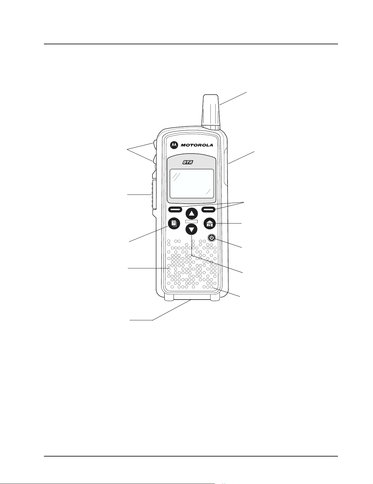
Your DTR Series Radio
Antenna
Volume Controls
Push-to-Talk (PTT)
Button
Menu Key
Speaker
Plug-in Charging
and Connect Data
Accessories
550
Audio Jack
Connect audio accessories
Option Keys
Use to select display options
Home Key
Use to exit the current menu
and return to the idle screen
Power Button
Navigation Keys
Use to scroll menu settings
Microphone
9980384R89-O February 10, 2005
Page 12
1-4 Introduction: Getting Started
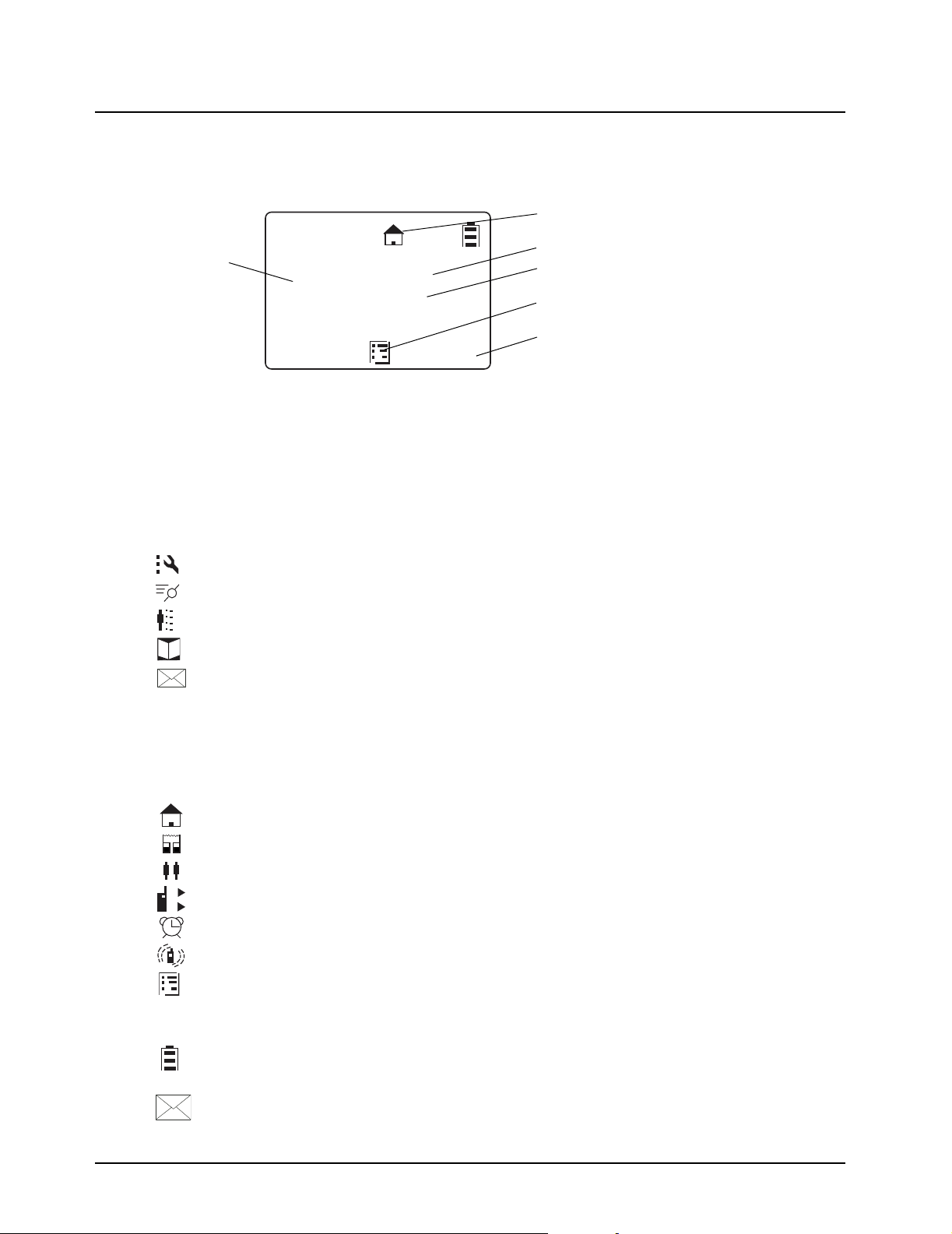
Getting Started
Any time your radio is powered on, the display provides you with information and options.
Menu/Status Icons
Te xt Area
The display shown is in idle. The idle screen appears when your radio is on, but not engaged in any
activity.
Menu Icons
Menu icons appear when you are accessing a particular menu. The icon for that menu appears in
the upper left corner of the display.
User Name
JOE SMITH
Security
5:49pm 11/14
Contcs
Settings Customize your radio.
Recent Calls Lists recent calls.
My Info View personal radio information.
Contacts Create, view, store, edit contacts.
Messages View, reply, create, send messages.
Mesgs
Scroll Setting
Menu Icon
Display Options
Status Icons
Status icons usually appear in first row at the top of the display. Some appear at all times. Others
appear only when your radio is engaged in certain activities or when you have activated certain
features.
1
2
A
B
C
Home The private or group contact shown is on your home channel.
PublicGroup The contact selected is a PublicGroup.
PrivateGroup The contact selected is a PrivateGroup.
Call Forward Your radio is set to forward calls.
Alarm The alarm has been set.
VibraCall Your radio is set to vibrate when receiving an alert or text message.
Menu Main Menu.
Te xt Input Indicates you are entering text. The mini keyboard must be att ached
to the radio
Battery Status More bars on the battery indicate a greater charge. When the
battery is flashing, it is time to charge the radio.
New Message You have a new unopened text message.
February 15, 2005 9980384R89-O
Page 13

Introduction: Battery 1-5
Text Area
This area displays menus, messages, unit names or IDs, and other information.
Display Options
Two display options appear at the bottom of most screens. You select a display option by pressing
the below it.
Menu Key
Many features provide context-sensitive menus that let you access related features and actions. the
icon appears any time a context-sensitive menu is available. Press to access the menu.
Menus and Lists
Your radio’s features are ar range d in men us, submenu s, and list s . To access the items in a menu or
list, scroll using either the or keys.
Battery
WARNING: To avoid a possible explosion: DO NOT replace the battery in any area labeled
“hazardous atmosphere.” DO NOT discard batteries in a fire.
Battery Life
Your radio uses a rechargeable Lithium Ion (Li-Ion) battery.
Based on 5% transmit, 5% receive, 90% standby (standard duty cycle):
• NNTN4655 Li-Ion; Up to 19 Hours
• SNN5706 Li-Ion; Up to 14.5 Hours
Battery life is determined by several factors. Among the more critical are the regular overcharge of
batteries and the average depth of discharge with each cycle. Typically, the greater the overcharge
and the deeper the average discharge, the fewer cycles a battery will last.
For example, a battery which is overcharged and discharged 100% several times a day, lasts fewer
cycles than a battery that receives less of an overcharge and is discharged to 50% per day. Further,
a battery which receives minimal overcharging and averages only 25% discharge, lasts even longer.
WARNING: Care should be taken to avoid external short circuiting of the battery. A
Motorola batteries are designed specifically to be used with a Motorola charger and vice versa.
Charging in non-Motorola equipment may lead to battery damage an d void the battery warr anty. The
battery should be at about 77°F (25°C) (room temperature) , whenever possible. Charging a cold
battery (below 50° F [10°C]) may result in leakage of electrolyte and ultimately in failure of the
battery.
sustained high-rate discharge (for example, a paper clip placed accidentally
across the battery contacts) may permanently damage the battery, void the
battery warranty, and create a burn or fire hazard.
Charging a hot battery (above 95°F [35°C]) results in reduced discharge capacity, affecting the
performance of the radio. Motorola rapid-rate batter y chargers contain a temperature-sensing circuit
to ensure that batteries are charged within the temperature limits stated above.
WARNING: Do not attempt to change or charge the battery in a hazardous atmosphere.
To charge the battery, place the battery (with or without the radio) in a Motorola-approved charger.
9980384R89-O February 15, 2005
Page 14
1-6 Introduction: Charging the Radio
Charging the Radio
While the radio is charging, the display lights and the battery status icon flashes to show the status.
The battery will charge in approximately 1-3 hours, and battery gauge will show all segments and
stop flashing when fully charged.
Charging using the Drop-in Charging Tray
NOTE: Use of the Drop-in Charging Tray is recommended for daily use.
1. Place the charging tray on a flat surface.
2. Connect the plug-in charger and drop-in ch arging tray by inserting the plug into the rear of the
drop-in charging tray.
3. Plug the charger into an AC outlet.
4. Insert the radio (with battery installed) into the charging tray.
NOTE: The charging tray has been designed to charge the radio with or without the holster.
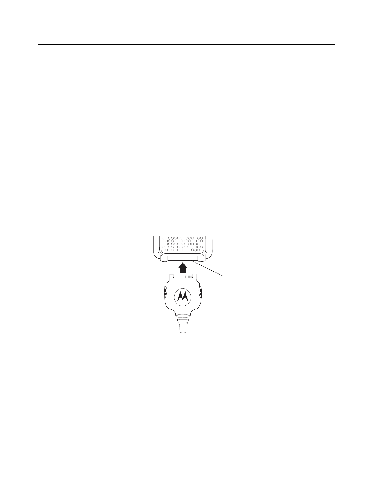
Charging using the Plug-in Charger
1. Plug the charger into an AC outlet.
2. Open the accessory connector cover.
3. Plug the other end of the charger into the accessory connector.
4. Disconnect the charger from the radio by pressing the two side buttons on the charger and
remove from the radio.
Accessory Connector
February 15, 2005 9980384R89-O
Page 15
Introduction: Attaching the Battery 1-7
Charging a Radio and Battery using a Multi-Unit Charger
A Multi-Unit Charger (MUC) is available separately (RPN4040) which will charge up to 6 radios,
batteries, or a combination of the two at the same time.
When charging a radio in the MUC, the battery icon on the radio display shows the charging status.
When charging a battery, the LED in front of the pocket indicates charging status. The LED is solid
red when the battery is charging, and solid green when charging is complete.
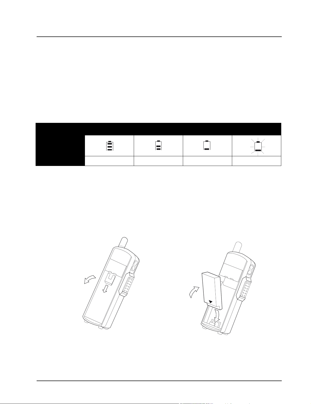
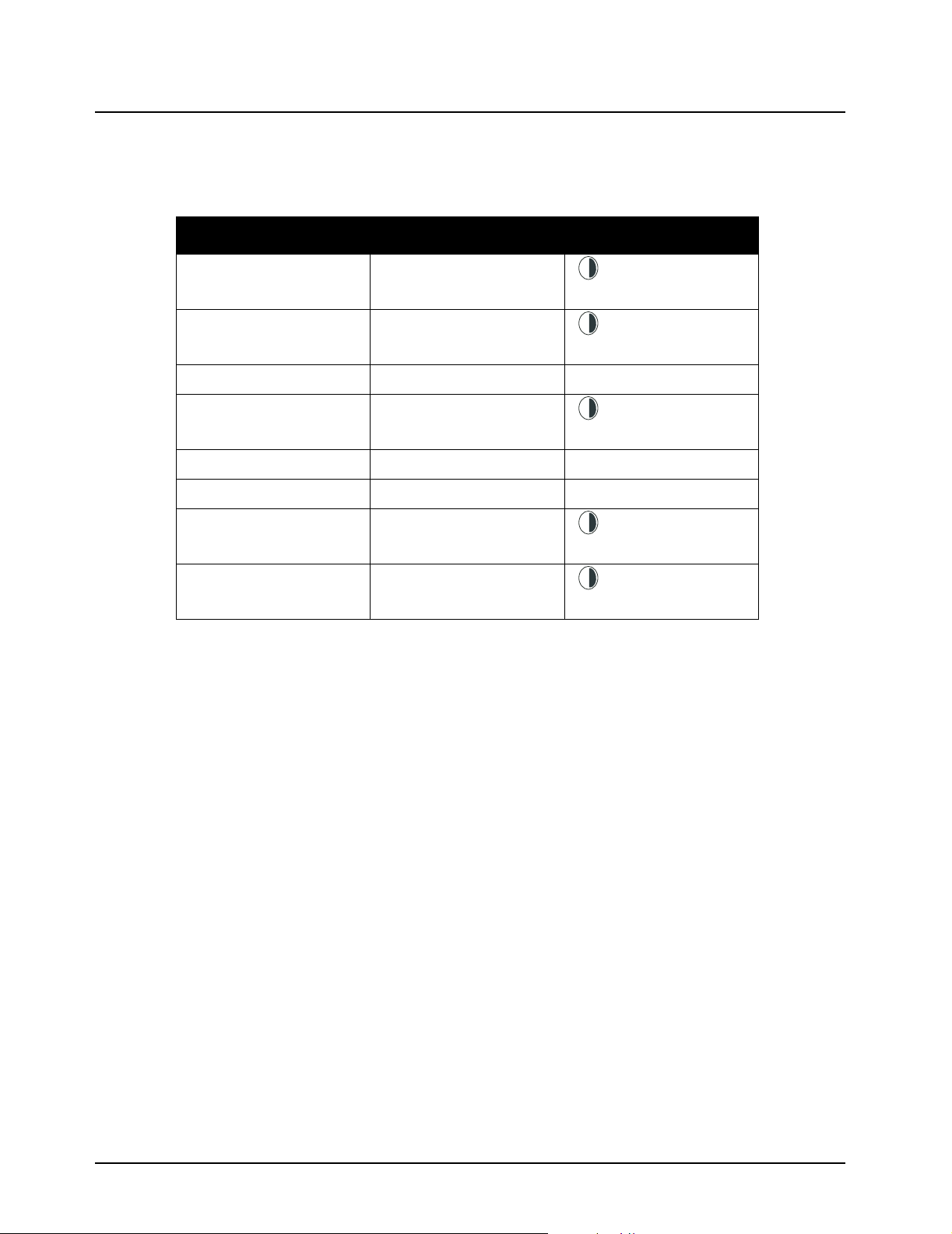
Battery Meter
The battery meter in the upper right corner of the radio display shows how much battery power is remaining:
Battery Type 3 Bars 2 Bars 1 Bar Flashing
Li-Ion
100%–85% 85%–25% 25%–10% Final 10%
Attaching the Battery
1. If the battery door is already in place, push down on the latch at the top and lift the door off
the radio.
2. Insert the battery, printed arrows first, into the battery compartment and press down to secure
firmly in place.
3. Replace the battery door onto the radio and slide the latch into place.
9980384R89-O February 10, 2005
Page 16
1-8 Introduction: Swivel Belt Holster
Swivel Belt Holster
1. Slide the bottom of radio into the holster and push the top of the radio against it until it snaps
into place.
2. To remove, push the tab located on top of the holster and pull the radio from it.
NOTE: In case of loss, please contact your point-of-sale to request replacement part number
RLN5713.
Mini Keyboard
A mini keyboard accessory (NNTN5491) is available separately that can be attached to your radio.
The mini keyboard allows you to customize Private and Group names, write text messages, and
create/modify stored text messages.
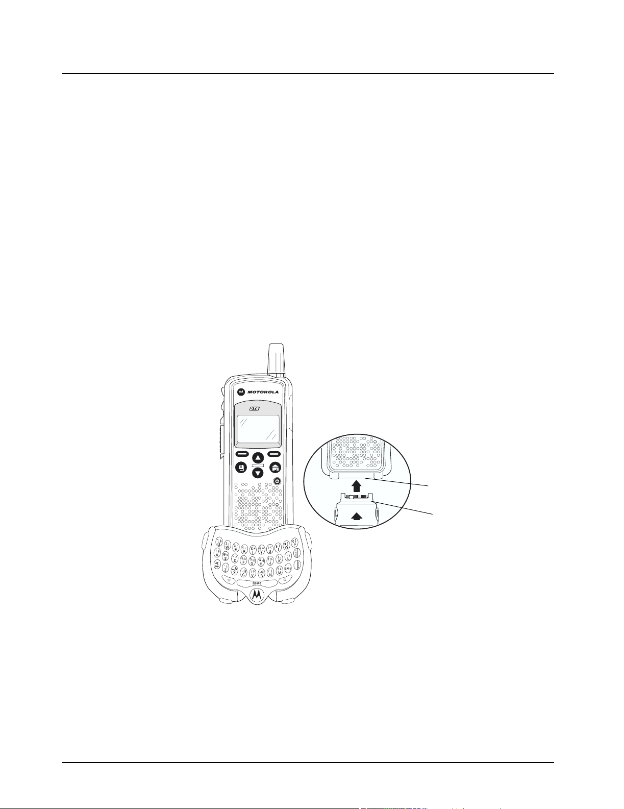
Attaching the Mini Keyboard to the Radio
When the mini keyboard is attached to your radio, the “Device Attached” message is displayed.
1. Insert the mini keyboard's connector, with the arrow facing up, into your radio’s accessory
connector.
2. Fold the mini keyboard over the front of your radio.
550
Disconnecting the Mini Keyboard from Your Radio
1. Press and hold the buttons on the side of the mini keyboard connector.
2. Pull the mini keyboard connector straight out from your radio’s accessory connector. Do not
twist the connector.
Accessory Connector
Keyboard Connector
February 10, 2005 9980384R89-O
Page 17

Introduction: Mini Keyboard 1-9
Entering Text with the Mini Keyboard
If you have attached the mini keyboard correctly and the keyboard bezel is installed on the keyboard
base you can begin.
Here are some important points to remember when using the mini keyboard.
• Your radio accepts a maximum of 512 characters in its largest input fields.
• Some of your radio's functions cannot be used simultaneously, just as when you are using your
radios without the mini keyboard.
• Letters and functions shown in white are the default keys.
• All letters are lower case by default. For example, pressing the "Q" key displays "q."
• The Bspc key works as a Back Space key when entering a message.
• The Space key works as a Space Bar.
Yellow/Lock Key Functionality
1. Press the Yellow key once. The next key pressed displays the yellow character on that key.
The keyboard will then return to the default keys (as if the yellow key had not been pressed).
• For example, press the Yellow key followed by the "Q" key, and a "1" displays. If "Q" is pressed
again, a "q" displays.
2. Press the Yellow key twice to lock the keyboard in the yellow mode. All subsequent key
presses display the yellow character associated with the key pressed. The keys that do not
have yellow functions (Left Option, Right Option, Bspc, Space) will still operate in the default
(white) mode.
3. Press the Yellow key again to unlock the yellow mode and revert back to the default (white)
mode.
4. Press the Green key to cancel the yellow mode and enter the green mode.
5. Press the CAPS key to cancel the yellow mode and enter the CAPS mode.
Green/Lock Key Functionality
1. Press the Green key once. The next key pressed displays the Green character on that key.
The keyboard will then return to the default keys (as if the green key had not been pressed).
• For example, press the Green key followed by the "U" key, and a "{" displays. If "U" is pressed
again, a "u" displays.
2. Press the Green key twice to lock the keyboard in the green mode. All subsequent key
presses display the Green character or function associated with the key pressed. The keys
that do not have green functions still operate in the default (white) mode.
3. Press the Green key again to unlock the green mode and revert back to the default (white) mode.
4. Press the Yellow key to cancel the green mode and enter the yellow mode.
5. Press the CAPS key to cancel the green mode and enter the CAPS mode.
CAPS Key Functionality
1. Press the CAPS key once. The next key pressed displays the capitalized character on that
key. Subsequent keys pressed will be displayed lower case.
2. Press the CAPS key twice to lock the keyboard in the caps mode. All subsequent key presses
display the capitalized character associated with the key pressed.
3. Press the CAPS key again to unlock the caps mode and revert back to the lower case mode.
4. Press the Yellow or Green key to unlock the caps mode and enter the yellow or green mode,
respectively.
9980384R89-O February 10, 2005
Page 18

1-10 Introduction: Mini Keyboard
Standard Yellow Function Green Function
Standard Yellow Function Green Function
Q1APOSTROPHE
W2 "
E3~
R 4 ACCENT
T5+
Y6^
U7 {
I8}
O9 [
P0 ]
A!#
S@<
D*>
F $ UP ARROW
G % DOWN ARROW
H&LEFT ARROW
J ( RIGHT ARROW
K)=
L:;
Z- ¡
X_Å
C.ß
V\Þ
B,Æ
N/ I
M?¿
February 10, 2005 9980384R89-O
Page 19
Introduction: Mini Keyboard 1-11
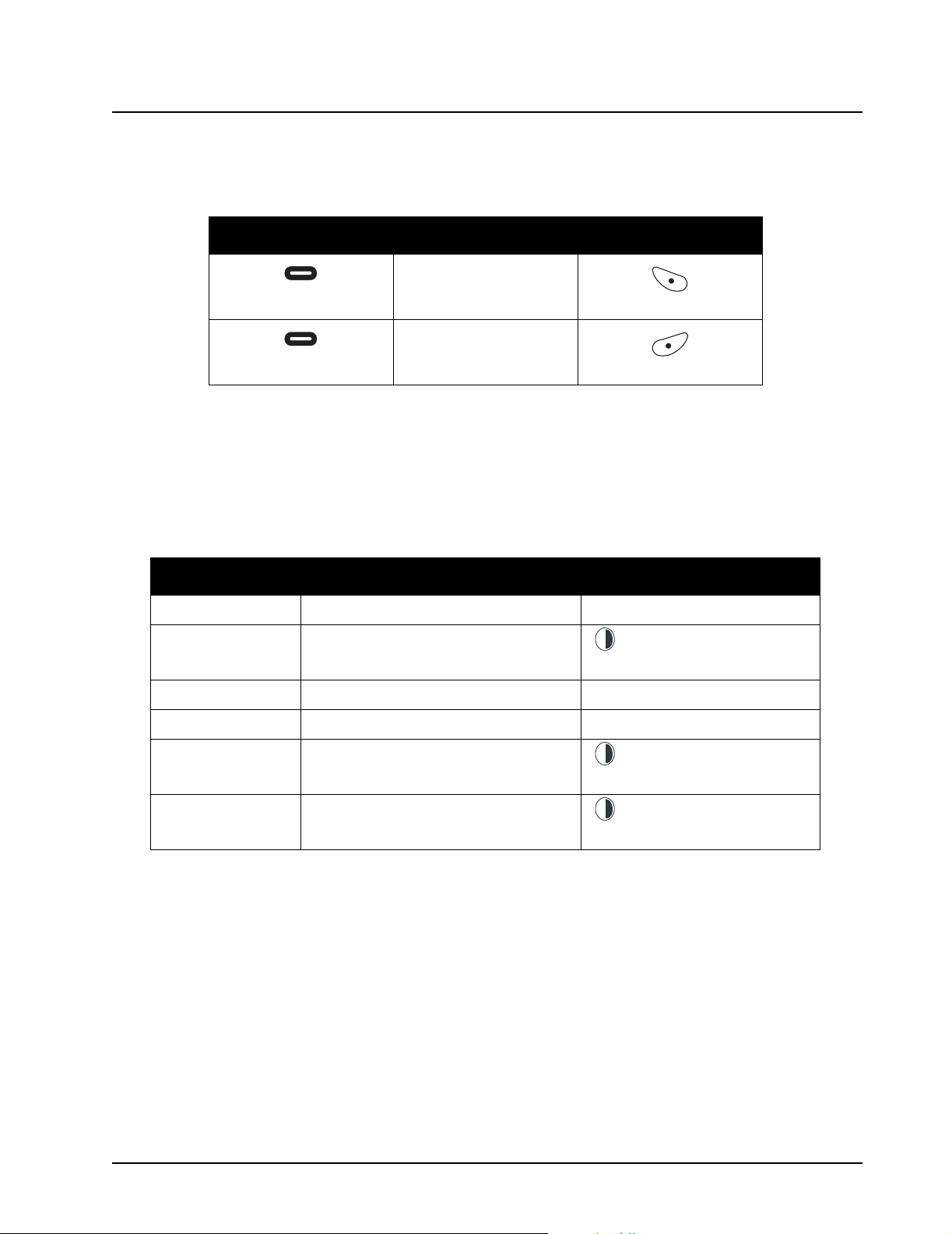
Using Mini Keyboard Key Shortcuts
You can perform most of your radio’s functions using the keys on the Motorola mini keyboard.
Radio Key Action Keyboard Equivalent
Chooses current left
Left Option
display option
Left Option Key
Chooses current right
Right Option
display option
Right Option Key
Extended Character Set
The mini keyboard lets you enter special characters using a combination of keystrokes.
NOTE: The extended character set is only available if your radio is configured for a language other
than English.
Accent Example Description Keystrokes
Accent Marks
To create a letter with an accent mark over it, enter the keystrokes listed in the table above.
If your radio displays a language other than English, you must press the right arrow after a single
quote, ~, ', /, -, or ^ for the character to appear.
å acute accent (for letters a, e, i, o, u, y) single quote, then letter
L
o
â circumflex (for a, e, i, o, u + Y+ letter
c
k
Green
ä umlaut (for letters a, e, i, o, u) shift and quote, then letter
à grave accent (for letters a, e, i, o, u) grave accent, then letter
L
o
ã tilde (for letters a, n, o) + ~ + letter
c
k
Green
L
o
Å nordic A-ring (for letter a only) + X
c
k
Green
9980384R89-O February 10, 2005
Page 20
1-12 Introduction: Accessories
Other Special Characters
To create other special characters, enter the keystrokes listed in the table below.
Accent Example Description Keystrokes
L
o
ß sharp s, German sz ligature + C
Æ diphthong AE ligature + B
ç or Ç cedilla single quote, then c or C
Þ icelandic thom + V
ðor Ð icelandic eth dash and d or D
ø or Ø nordic O-Slash /, then o or O
¿ upside down? + M
¡ upside down! + Z
c
k
Green
L
o
c
k
Green
L
o
c
k
Green
L
o
c
k
Green
L
o
c
k
Green
Accessories
The DTR Series radios comes with a High Capacity Lithium-Ion battery and a Drop-in Charging Tray.
Various accessories are available for use with your DTR Series radio, including holsters, hands-free
accessories, headset accessories, a mini keyboard, and more.
To order additional accessories, contact your dealer or call (800) 927-2744.
February 10, 2005 9980384R89-O
Page 21
Chapter 2 General Radio Operations
Your radio is ready for use after a fully-charged battery has been installed. However, your radio
should be programmed in order to be fully compatible with any existing DTR Series radios and to
fully utilize all radio features.
Refer to Chapter 3 - Advanced Radio Operations.
Turning Your Radio On or Off
Press to turn your radio on.
The radio chirps and the display briefly shows Motorola.
The display shows the radio Unit ID or Name, current Scroll list setting, time, date, and the available
Option key selections. If the radio has been assigned a unique Unit Name, the name will display
rather than the Unit ID for both the radio and any Contacts.
17179860200
Public1
5:49pm 11/14
Contcs
Press and hold to turn the radio off.
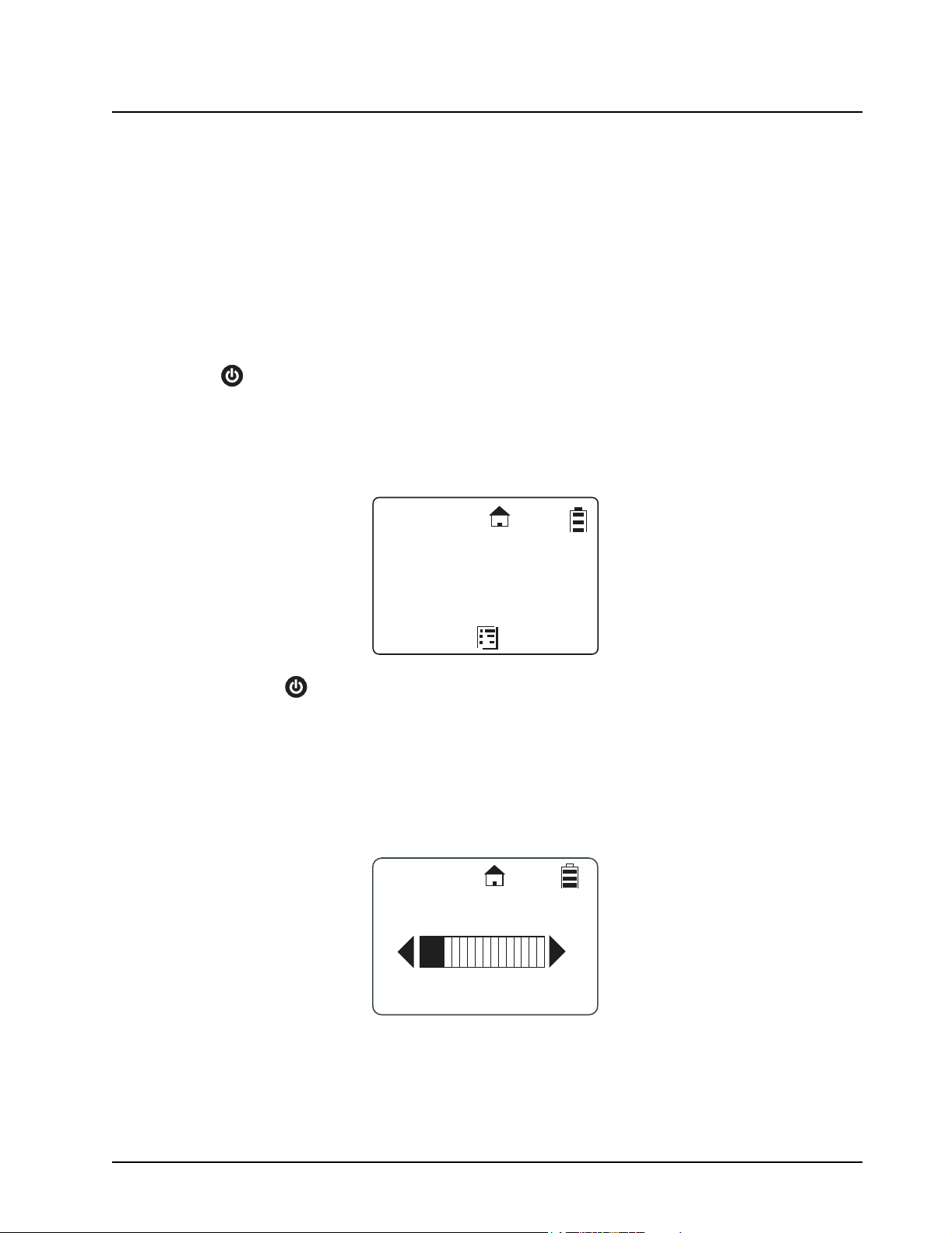
Adjusting the Speaker Volume
The Volume Control buttons are located on the upper left side of the radio. To adjust the speaker
volume, press the upper button to increase the volume level and press the lower button to decrease
the volume level. When either button is pressed, the display shows a bar chart indicating the present
level for the volume.
Mesgs
Volume
3
Page 22

2-2 General Radio Operations: Selecting a Scroll List Contact
Selecting a Scroll List Contact
In idle mode, use or to select the desired TalkGroup/Private contact. Press the PTT button
for one-touch communication.
Viewing a Contact
1. From the main screen, press under Contcs to enter the Contact List.
JOE SMITH
Security
5:49pm 11/14
Contcs
The Contact List screen appears with the first contact highlighted in the list.
Mesgs
Contacts
Mike Jones
Receiving
Security
Alert
2. Scroll to highlight the desired contact.
3. To view the contact, press under View for Group contacts or press and press
under View for Privace contacts. The display changes and shows the contact (group
number or name), the ID number, and the channel number.
Back
Mike Jones
Mike Jones
17178565789
Channel 1
Back
NOTE: For PrivateGroup contacts, members of the group are viewed by pressing under
Member.
February 10, 2005 9980384R89-O
Page 23

General Radio Operations: Receiving and Making Calls 2-3
Receiving and Making Calls
NOTE: Your DTR Series radio must be programmed to be fully compatible with other DTR Series
radios and fully utilize all radio features. Refer to Chapter 3 - Advanced Radio Operations.
Types of Calls
Your radio can make and receive three different types of voice calls:
• PublicGroup – One-to-many communication to all radios set to your channel and PublicGroup
number. All DTR Series radios are factory programmed with 2 to 5 PublicGroups.
• Private – One-to-one communication with another radio, requires adding a user to the Contacts
List.
• PrivateGroup – One-to-many communication to only radios in your group. Requires adding all
members to your Contact List then cloning the group (either over the air or with the RRDN5378
cloning cable) to member radios. Offers a higher level of privacy than a PublicGroup.
Receiving a Call
When a call is received, the radio chirps and the display shows the call type and transmitting caller’s
user ID or name.
Making a Call
1. Choose a contact from your Scroll List, Contacts, or Recent Call List.
2. Press and hold the PTT button. Begin speaking after the radio emits the talk permit tone. To
3. Release the PTT button to listen.
NOTE: If “User Not Available” displays, the recipient is either: In a Call, Out of Range, or Turned Off.
Talkgrp in Use
Security
Private in use
Mike Jones
(Joe Smith)
maximize clarity, hold the radio two-to-three inches away from your mouth.
Press to cancel and then try the call again. When contacting a group, at least one
member must be available for the call to be successful.
9980384R89-O February 10, 2005
Page 24

2-4 General Radio Operations: Call Alerts
Call Alerts
Sending a call alert lets the recipient know you want to talk to him or her. When you send a call alert,
the recipient's radio emits a series of beeps, or vibrates, and displays your Unit Name or ID along
with the time and date.
The recipient can:
• Answer – begin a call by pressing the PTT button.
• Clear – delete the call alert.
Sending Call Alerts
NOTE: Only Private Contacts can be alerted.
1. Highlight the Private Name/ID in Contacts or Recent Calls..
Contacts
Shipping
Maintenance
Smith
2. Press under Alert. “Ready to Alert” appears on the display.
3. Press the PTT button until “Alert Successful” appears on the display.
NOTE: If the alert is not successful, the radio you are trying to reach is either in a call, on another
channel, has the radio turned off, or is out of range.
Receiving a Call Alert
When you receive a call alert, you must answer or clear it. You cannot make new calls until you do.
To answer a call alert, press the PTT button to respond to the sender. To clear a call alert, press
under Clear.
Alert
Alert
Smith
9:46pm 11/18
Back
Clear
February 10, 2005 9980384R89-O
Page 25

General Radio Operations: Text Messaging 2-5
Text Messaging
Your radio can send and receive short text messages to Private or Group contacts. Your radio must
be on and within range to receive text messages.
Receiving a Message
When you receive a text message, “New Message Received” appears on the display. The sender
and group (if applicable) are also indicated.
New Message
Received
From Jones
To View the Message
1. Press under Read to read the message.
NOTE: If you are in a menu when the message is received, you will need to exit and read it from the
Inbox.
2. If the message fills more than one screen, scroll to read the entire message.
3. To delete the message, press and press under Delete.
To Dismiss the Message Notification
Press under Back to read the message at a later time. This icon appears on the display,
reminding you that you have an unread message.
Reading from the Inbox
1. Press under Mesgs.
2. Scroll to the message you want to read.
3. Press under Read.
4. If the message fills more than one screen, scroll to read it.
Read
Back
Inbox
[Send Mesg]
Are you at
No
Read Back
9980384R89-O February 10, 2005
Page 26

2-6 General Radio Operations: Text Messaging
Replying to a Received Message
Your radio has a number of pre-programmed Quick Notes available, or the mini keyboard can be
used to create a response. Additional Quick Notes can be created and the existing ones modified/
deleted with the mini keyboard by selecting Text Messaging while in Programming Mode.
1. To reply to the message, press under Reply.
Detailed View
From:Jones
Are you at wo..
Reply
2. The Send Message screen appears.
NOTE: If the mini keyboard is connected to the radio, the [Write Mesg] option appears on the display.
Refer to Composing a Message Using the mini keyboard.
Back
Send Message
Are you at wor..
Can you meet...
I can’t take y..
Select
3. Scroll to highlight a reply message and press under Select to select the reply message. The Compose Msg. screen appears.
Back
Compose Msg
To:Jones
Mesg:Can you mee
View
4. To change the Contact you are sending to, press under Change. This will return you to
the Contact List. Scroll to select the correct Contact and press under Select.
5. To view the text messages in the list, scroll to select the message and press under
View.
6. Press under Send to send the reply.
February 10, 2005 9980384R89-O
Send
Page 27

General Radio Operations: Text Messaging 2-7
Sending a Text Message
Your radio can send and receive short text messages to Private or Group contacts, and has several
pre-programmed Quick Notes available. The mini keyboard can be used to change, add additional,
or delete these messages while in Programming Mode. This accessory can also be used to write
new messages from User Mode.
1. Press under Mesgs. The message inbox is displayed.
JOE SMITH
Security
5:49pm 11/14
Contcs
2. Highlight [Send Mesg] and press under Select.
Mesgs
Inbox
[Send Mesg]
Select Back
3. The Send Message screen appears.
NOTE: If the mini keyboard is connected to the radio, the [Write Mesg] option appears on the display.
Refer to Composing a Message Using the mini keyboard.
4. Scroll to select the message you want to send.
Send Message
Are you at wor..
Can you meet...
I can’t take y..
Select
Back
9980384R89-O February 10, 2005
Page 28

2-8 General Radio Operations: Text Messaging
5. Press under Select to choose the message. The display shows the Contact and the
message you want to send
Compose Msg
To:Jones
Mesg:Can you mee
View
6. To change the Contact you are sending to, press under Change. This returns you to
the Contact List. Scroll to select the correct Contact and press under Select.
7. To view the text messages in the list, scroll to select the message and press under
View. If the message fills more than one screen, scroll to read it.
8. Press under Send to send the message.
Composing a Message Using the Mini Keyboard
The mini keyboard can be used to type either new messages or replies.
1. From the Send Message screen, highlight the [Write Mesg] option and press under
Select .
Send Message
[Write Mesg]
Select
Send
Back
2. The Compose Msg screen appears.
Compose Msg
To:Jones
Mesg:(Empty)
Change
3. To change the Contact you are sending to, press under Change. This returns you to
the Contact List. Scroll to select the correct Contact and press under Select.
February 10, 2005 9980384R89-O
Send
Page 29

General Radio Operations: Text Messaging 2-9
4. Scroll to highlight the Mesg: option. Press under Change.
5. The Mesg: screen appears. Use the mini keyboard to enter your message.
A
B
C
Mesg:
NOTE: The under Delete can be used to erase characters. Holding will delete the entire
message.
6. Once the message is completed, press under Done.
7. Press under Send to send the message. The display shows a confirmation that the
message was sent.
Deleting a Message
1. From the idle screen press under Mesgs to enter the Message Inbox.
2. Scroll to select a message for deletion.
3. After selecting a message, press . The Inbox displays the delete selections. If only the
one message is to be deleted, highlight Delete and press under Select.
Done
Inbox
Delete
Delete All
Delete
Select
4. If all messages in the Inbox are to be deleted, highlight Delete All and press under
Select. A confirmation screen appears.
Back
Delete All
Messages?
Yes
5. Press under Yes to delete all messages.
9980384R89-O February 10, 2005
No
Page 30

2-10 General Radio Operations: Accessing the Main Menu
Accessing the Main Menu
1. Press to access the Main Menu. The Main Menu appears.
Main Menu
Recent Calls
Settings
My Info
Select
2. Scroll through the available menu options. Highlight the desired menu option and press
under Select.
Main Menu Navigation Chart
Recent Calls
Back
Display
Main Menu
to enter main menu
or to scroll through list
to select display option
Settings
My Info
VibraCall
Clock/Alarm
Scroll List
Volume
Call Forward
Advanced
Remote Disable*
Remote Monitor*
to exit main menu
* Menus only appear on the DTR650 radio when Manager Mode is enabled.
February 10, 2005 9980384R89-O
Remote Time*
Page 31

General Radio Operations: Recent Calls 2-11
Recent Calls
This menu lists recent calls received and allows the user to view, alert or delete recent calls on the
list. From the Main Menu, scroll to highlight Recent Calls and press under Select.
Viewing a Recent Call
1. Scroll to select a recent call from the list. To view GroupCall details, press under View.
To view PrivateCall details, press . The Rec. Call Menu appears.
NOTE: The graphic to the left of the user/group name or ID indicates whether the call was received
(pointing left) or initiated (pointing right)..
Recent Calls
Smith
Jones
Security
View
Back
2. Scroll to show call details for the selected call. These include Group Name (if applicable),
User Name and ID, time, date, and length of call. Continuing scroll moves you to the next
recent call
3. Press under Back to access the previous screen.
Alerting a Recent Caller
NOTE: Only Private contacts can be alerted.
1. Scroll to select a recent call from the list and press under Alert.
Call Details
Office
Smith
9:03am 11/22
Recent Calls
Smith
Jones
Security
Alert
Back
Back
2. Press the PTT button to send the alert.
NOTE: If the alert was successful, a confirmation screen appears. If the alert was not successful, an
unsuccessful screen appears.
9980384R89-O February 10, 2005
Page 32

2-12 General Radio Operations: Settings
Deleting Recent Calls
1. Scroll to highlight a recent call from the list.
2. Press . The Rec. Call Menu appears.
Rec.CallMenu
View
Delete
Delete All
NOTE: View only appears as a menu option for Private calls.
Settings
The Settings menu allows you to adjust personal settings that include Display, VibraCall, Clock/
Alarm, Volume, and Advanced. The Advance features are for managing your Scroll List, Call
Forwarding, Remote Disable, Remote Monitor, and Remote Time. Refer to Chapter 3 – Advanced
Radio Operations to operate the Advance features.
Select
3. Scroll to highlight Delete to remove only the one call or Delete All to delete all recent calls
and press under Select.
4. Select under Yes or No. The display confirms that the call or calls have been deleted
and then returns to the Recent Calls list.
Back
Delete:
Smith?
Yes No
From the Main Menu, scroll to highlight Settings and press under Select. The Settings menu
appears.
Settings
Display
Vibracall:On
Clock/Alarm
Select
February 10, 2005 9980384R89-O
Back
Page 33

General Radio Operations: Settings 2-13
Setting the Display
From the Settings menu, scroll to highlight Display and press under Select. The Display
menu appears. From the Display menu, you can adjust the contrast and backlight time.
Display
Contrast:2
Backlight:10
Adjusting the Contrast
1. From the Display menu, scroll to highlight Contrast and press under Change. The
Contrast screen appears.
2. Use or to adjust the Contrast as necessary and then press under OK to return
to the previous menu.
Setting the Backlight
1. From the Display menu, scroll to highlight Backlight and press under Change. The
Backlight screen appears. The presently selected value will have a check mark on the left
side.
Change
Contrast
OK
Back
4
Cancel
Backlight
Off
5 Seconds
10 Seconds
Select
2. Scroll to highlight the desired value. You can set the backlight time to Off, 5, 10, 20, 30, or 90
seconds.
3. Press under Select to save the setting and return to the previous screen.
9980384R89-O February 10, 2005
Back
Page 34

2-14 General Radio Operations: Settings
Setting VibraCall
VibraCall allows you to set the radio to vibrate with no audio alert tones when text messages or call
alerts are received.
NOTE: This does not mute the audio for voice calls.
1. From the Settings menu, scroll to highlight VibraCall and press under Select. The VibraCall screen appears. A checkmark is displayed to the left of the present selection.
Vibracall
On
!
Off
2. Scroll to highlight the desired selection.
3. Press under Select to save the selection and return to the previous menu.
NOTE: When turning vibrate on, the radio will briefly vibrate and appears on the display.
Clock and Alarm
Your radio requires that the current time and date be set in order to fully utilize the digital features.
This can be set manually or by using the Remote Time feature (see page 3-5)
From the Settings menu, scroll to highlight Clock/Alarm and press under Select. The Clock/
Alarm menu appears.
Select
Clock/Alarm
Time:10:20am
Date:11/22
Set Alarm
Change
Back
Back
February 10, 2005 9980384R89-O
Page 35

General Radio Operations: Settings 2-15
Setting the Time
1. From the Clock/Alarm Menu scroll to highlight Time and press under Change. The
Time screen is displayed.
Time:
< >
: 20am
10
2. Scroll to select the desired hour.
NOTE: Press and hold or to fast scroll.
3. Press under --> to move to the minutes and scroll to select the desired minutes.
4. Press under --> to move to am/pm and scroll to select the desired setting.
5. After completing the time setting press under Done to complete the setting and to
Setting the Date
1. From the Clock/Alarm menu, scroll to highlight Date and press under Change. The
__
return to the previous menu.
Date screen is displayed.
__
>
Date:
< >
/ 31 / 05
03
>
Done
THU
Done
2. Scroll to select the desired Month.
NOTE: Press and hold or to fast scroll.
3. Press under --> to move to the day and scroll to select the day.
4. Press under --> to move to the Year and scroll to select the Year.
5. After completing the date setting, press under Done to complete the entry and return to
the previous menu.
9980384R89-O February 10, 2005
Page 36

2-16 General Radio Operations: Settings
Setting the Alarm
Your DTR Series radio has an alarm feature that can be set to remind you of a recurring daily event.
From the Clock/Alarm menu, scroll to highlight Set Alarm and press under Select. The Set
Alarm menu appears.
Set Alarm
Alarm:Off
Time:12:00am
Change
The Set Alarm menu allows the Alarm to be turned Off or On and to set the Alarm Time.
1. Scroll to highlight Alarm and press under Change. The alarm menu is displayed with
On and Off listed. A check mark to the left of On or Off indicates the present selection.
Back
Alarm
Off
On
!
Select
2. Scroll to select the desired condition and press under Select. The display returns to the
Set Alarm menu with the new selection indicated.
NOTE: When the Alarm is set to On, the icon appears on the display.
3. Scroll to highlight Time and press under Done. The alarm time is set using the same
procedure as for setting the Time.
Back
Time:
< >
: 20am
10
__
>
4. Scroll to select the desired hour.
NOTE: Press and hold or to fast scroll.
5. Press under --> to move to the minutes and scroll to select the desired minutes.
6. Press under --> to move to am/pm and scroll to select the desired setting.
February 10, 2005 9980384R89-O
Done
Page 37

General Radio Operations: Settings 2-17
7. After completing the time setting press under Done to complete the setting and to
return to the previous menu.
Setting the Volume
The functions of the various selections are as follows:
Ringer: volume level for all data status alerts such as Alert Tones and incoming SMS Messages.
Turning VibraCall on changes this level to 0.
Speaker: volume level for voice messages.
Keypad: volume level for keypad presses.
Alarm: volume level for the Alarm feature, which is overridden by VibraCall.
From the Settings menu, scroll to highlight Volu m e and press under Select. The Volume
menu appears.
Volume
Ringer:6
Speaker:7
Keypad:1
Change
Back
NOTE: Highlighting any of the volume choices and pressing the Volume Control keys automatically
adjusts the volume levels.
NOTE: Pressing the Volume Control keys while not in the Volume menu only sets the Speaker
Volume.
Setting the Ringer Volume
1. From the Volume menu, scroll to highlight Ringer and press under Change. The
Ringer screen appears.
2. Use the Volume Control keys to adjust the Ringer volume as necessary and then press
under OK to save the selection and return to the previous menu.
OK
Ringer
3
Cancel
9980384R89-O February 10, 2005
Page 38

2-18 General Radio Operations: My Info
Setting the Speaker Volume
1. From the Volume menu, scroll to highlight Speaker and press under Change. The
Speaker screen appears.
Speaker
6
2. Use the Volume Control keys to adjust the Speaker Volume as necessary and then press
under OK to save the selection and return to the previous menu.
Setting the Keypad Volume
1. From the Volume menu, scroll to highlight Keypad and press under Change. The Keypad screen appears.
2. Use the Volume Control keys to adjust the Keypad Volume as necessary and then press the
Ok Option key to save the selection and return to the previous menu.
My Info
OK
Ok
Cancel
Keypad
1
Cancel
The My Info screen displays your Unit Name, ID and Channel. From the Main Menu, scroll to
highlight My Info and press under Select.
NOTE: The Unit Name defaults to Unit ID unless it is customized in programming mode using the mini
keyboard.
My Info
Joe Smith
17179869143
Channel 1
Back
February 10, 2005 9980384R89-O
Page 39

Chapter 3 Advanced Radio Operations
Accessing the Advanced Menu
The Advanced features are for managing your Scroll List, Call Forwarding, Remote Disable, Remote
Monitor, and Remote Time.
NOTE: Remote Disable, Remote Monitor, and Remote Time are not available, unless Manager Mode
has been enabled in Programming Mode (DTR650 model only).
From the Settings menu, scroll to highlight Advanced and press under Select. The Advanced
screen appears.
Advanced
Scroll List
Call Forward
Remote Disable
Select
Back
Managing Your Scroll List
The Scroll List is designed to give one-touch communication to frequently used contacts. Any private
or PrivateGroup contact on your channel, or any PublicGroup can be added to the Scroll List.
Removing them does not remove them from contacts.
1. From the Advanced menu, scroll to highlight Scroll List and press under Select. The
Scroll List screen appears.
NOTE: A next to the left of the Group/Private contact indicates that the Group/Private contact is
already in the Scroll List. If the highlight is on a selected item, the left changes to
Remov. Pressing under Remov removes the check mark.
If no check mark is present, the entry has not been selected and will not appear in the Scroll
List. The left changes to Add. Pressing under Add inserts a check mark.
Scroll List
Joe Smith
!
Jones
!
Office
Remov
Back
2. Press under Add or Remov.
Page 40

3-2 Advanced Radio Operations: Accessing the Advanced Menu
Enabling Call Forwarding
Call Forwarding allows a user to notify anyone contacting them that they are not available and
suggest a manager or third party to be contacted in their absence. The user contacting them can
then choose to transmit to the third party by simply pressing the PTT button.
NOTE: Your radio must be on and within range to use this feature while you are away.
1. From the Advance menu, scroll to highlight Call Forwarding and press under Select.
The Call Forwarding screen appears.
1
2
Call Forward
Forwarding:On
To:Joe Smith
1
2
Back
Charge
2. Scroll to highlight Forwarding and press under Change. The Forwarding screen
appears.
3. Scroll to select the desired function and press under Select to return to the previous
screen.
NOTE: When Call Forwarding is enabled, the icon appears on the display
4. To change or select the radio to receive the forwarded calls, scroll to highlight the To: function
and press under Change.
1
2
Call Forward
Forwarding:On
To:Joe Smith
Change
5. Scroll to select the radio name from the list to forward to. Press under Select.
Back
February 10, 2005 9980384R89-O
Page 41

Advanced Radio Operations: Accessing the Advanced Menu 3-3
Remote Disabling (DTR650 Models Only)
NOTE: Manager Mode must be enabled in order for a user to use this feature. Refer to page 4-9.
Remote Disabling allows a user to remotely enable or disable another DTR Series radio on their
channel. The selected radio must be turned on and within range in order to be enabled or disabled.
Advanced
Scroll List
Call Forward
Remote Disable
Select
1. From the Advance menu, scroll to highlight Remote Disable and press under Select.
The Remote Disable screen appears.
Back
Remote Disable
Joe Smith
Jones
Kevin
Enable
Disable
2. Scroll to highlight a radio name from the list. Press under either Enable or Disable.
The screen changes to confirm the selection.
NOTE: To cancel out of Remote Disable, press and press under Select.
3. To enable or disable the selected radio, press under either Yes or No.
Once the radio is disabled, the display shows “Radio Disabled” and the radio cannot transmit,
receive, or access it’s contacts.
Joe Smith
Radio Disabled
9980384R89-O February 10, 2005
Page 42

3-4 Advanced Radio Operations: Accessing the Advanced Menu
Remote Monitoring (DTR650 Models Only)
NOTE: Manager Mode must be enabled in order to use this feature. Refer to page 4-9.
Remote Monitoring allows you to monitor a selected radio either for training purposes or if the target
radio user is unable to press the PTT button.
1. From the Advance menu, scroll to highlight Remote Monitor and press under Select.
The Remote Monitor screen appears.
Remote Monitor
Joe Smith
Jones
Select
2. Scroll to highlight a radio from the list to monitor and press under Select. The screen
changes to show the radio’s status.
Remote Time (DTR650 Models Only)
Remote Time synchronizes the date and time to all other radios on your channel. Any receiving radio
must have the transmitting radio User ID in their contact list to accept the time/date update.
NOTE: Radios must be turned on and within range to receive this broadcast message. The
transmitting radio does not receive a confirmation for any failures.
1. From the Advance menu, scroll to highlight Remote Time and press under Select. The
screen displays a confirmation to start remote time.
Start Remote
Yes
Back
Time?
No
2. Press under Yes.
February 10, 2005 9980384R89-O
Page 43

Chapter 4 Radio Programming
Program Menu Navigation Chart
Contacts
Display
VibraCall
Program Menu
or to scroll through list
to select display option
to exit Program menu
Text Messaging
Settings
Clock/Alarm
Scroll List
Volume
Call Forward
Advanced
Radio History
Manager Mode*
Language
* DTR650 radio only.
Page 44

4-2 Radio Programming: Entering Programming Mode
Although factory programmed with default PublicGroups, DTR Series radios require user-specific
programming in order to fully benefit from their digital features.
This occurs in a separate programming mode which allows access to modify and add contacts,
update existing and add new quick notes, and access manager features (DTR650 only) such as
Remote Disable and Remote Monitoring. A mini keyboard (NNTN5491) is used to enter text into
contacts and to modify saved text messages.
The RRDN5378A Cloning Cable allows easier programming as one radio can be programmed with
all contact information then duplicated in other radios. All PrivateGroups MUST be programmed on a
single radio and cloned either over-the-air or with the cloning cable in order to maintain a single
GroupID. This is not a requirement of PublicGroups, but they must still be programmed on the same
channel to communicate.
New radios should be cloned using serial cloning. After this occurs, the unit ID can be sent to the
other radios or added to PrivateGroups via over-the-air or serial cloning.
Entering Programming Mode
The following key sequence must be performed to enter the programming mode.
1. Hold down and press the PTT button three times.
2. Press the Right .
The Program Menu screen appears.
My Info
3. Press .
4. Press the Left .
5. Hold down and press the PTT button three times.
Program Menu
Contacts
Text Messages
Settings
Select
1. Highlight Contacts and press under Select. A appears to the right of the display.
2. Scroll to select it and press under View. Your unit name, ID, and channel are shown.
3. Press under Edit to change the unit name or channel.
Reset
February 10, 2005 9980384R89-O
Page 45

Radio Programming: Adding Contacts 4-3
Adding Contacts
1. From the Program Menu, scroll to select Contacts and press under Select. The Con-
tacts screen appears.
Contacts
[New Contact]
Office
Security
Call Type
Select
2. Scroll to select [New Contact] and press under Select. The Private screen appears.
Back
Private 1
Type:Private
Channel:1
Name:Private1
Change
1. From the Private screen, scroll to select Type and press under Change. The Type
screen appears.
Cancel
Type
Private
!
Prv Group
Public Grp
Select
NOTE: A next to an selection indicates the present selection.
2. Scroll to select either a Private call type, PrivateGroup call type, or PublicGroup call type to
add to the Contact List. Press under Select.
3. The display returns to the previous screen with the new call Type entered.
9980384R89-O February 10, 2005
Back
Page 46

4-4 Radio Programming: Adding Contacts
Channel
Your radio operates using frequency-hopping technology. Each "Channel" is a group of 50
frequencies. Your radio can transmit and receive on up to 10 channels, but Group messages will not
be heard unless you are on the same channel.
The home icon on the display indicates that your current scroll list setting is on your channel. Your
radio will scan up to 5 groups per channel, and Private Calls are received regardless of channel.
1. Scroll to select Channel and press under Change. The Channel screen appears.
Channel 1
1
!
2
3
NOTE: The presently selected channel has a to the left of the channel number. Radios on the
Unit Name
Unit ID is transmitted with all voice and text messages. Programming a unique unit name to an ID will
cause the radio to recognize any incoming calls from that user or group and display their unit name.
NOTE: A mini keyboard (NNTN5491) must be connected to the radio to enter alphanumeric
Select
same TalkGroup should be set-up on the same channel.
2. Scroll to select a channel and press under Select. The display returns to the previous
screen with the new Channel entered.
characters.
1. Scroll to select Name and press under Change. The Name screen appears.
Back
Name:
Private 3
Ok
2. Press under Delete to remove characters one at a time or hold to delete all characters.
Use the mini keyboard to enter a new name. After entering the Name, press under Ok
to confirm the entry and to return to the previous screen with the new Name entered.
February 10, 2005 9980384R89-O
Delete
Page 47

Radio Programming: Adding Contacts 4-5
Programming a Unit ID (Private Calls Only)
The unit ID of a private contact can be read over the air or entered using the mini keyboard.
1. Scroll to select ID and press under Read. The ID screen appears.
On other radio
press Home 3
times then PTT
Cancel
2. Use the mini keyboard to enter an 11 digit ID. When the mini keyboard is connected, the left
becomes Change. After entering the ID, press under Ok to confirm the entry and
to return to the previous screen with the ID entered.
Selecting a Group ID
When programming a new PublicGroup, press under Change to select a PublicGroup ID from
1-100. IDs already in use on your radio will be preceded by an “x”.
When programming a new PrivateGroup, the radio selects your GroupID from your contact list.
Press under Change to select another Group ID. Since the default GroupID is dependent
upon the contact list of all radios being the same, it is recommended to clone PrivateGroups to other
radios.
Entering a Home Group Number (Private Calls Only)
If a Home Group is selected for your radio, then it will return to that Group after 30 seconds of
inactivity. This ensures that any transmissions on this channel are not missed. Selecting a Home
Group also automatically adds the contact to that PrivateGroup.
1. Scroll to select the Home Group Number and press under Change. The Home Group
screen appears.
Home Group
None
!
Office
Security
Select
NOTE: A next to a selection indicates the present selection.
Back
2. Scroll to select the desired entry. Press under Select to select the new item. The display returns to the previous screen with the new Home Group Number entered.
9980384R89-O February 10, 2005
Page 48

4-6 Radio Programming: Adding Contacts
Selecting Group Only
NOTE: Selecting Group Only on a radio prohibits the user from initiating PrivateCalls.
1. Scroll to select Group Only and press under Change. The Group Only screen
appears.
Group Only
Yes
None
No
!
Select
NOTE: A next to an selection indicates the present selection.
2. Scroll to select the desired entry and press under Select. The display returns to the
previous screen with the new Group Only entered.
Entering Group Members (PrivateGroup Only)
1. Scroll to select Group Members and press under Change. The Group Members
screen appears.
Group Members
Joe Smith
!
Mike Jones
Bob White
Add
NOTE: A next to the left of the Group Member indicates that those members are already part of
the TalkGroup assigned. If the highlight is on a checked item, the left changes to
Remov. Pressing under Remov removes the check mark.
If no check mark is present, the entry has not been selected and is not part of the
PrivateGroup already assigned. The left changes to Add. Pressing under Add
inserts a check mark.
Back
Done
2. Scroll through the list of Group Members and press under Add.
3. When completed, press under Done. The display returns to the previous screen with
the new Group Members entered.
February 10, 2005 9980384R89-O
Page 49

Radio Programming: Text Messaging 4-7
Entering a Ringer Type (Private Calls Only)
A unique alert tone can be identified for each radio in your contact list. There are 12 ringer tones that
can be selected. When a ringer tone is highlighted, the audio ringer tone sounds to help in making a
selection.
1. Scroll to select Ringer and press under Change. The Ringer screen appears.
Ringer
1
!
2
3
NOTE: A next to a selection indicates the present selection.
2. Scroll to select the desired ring. Highlighting a tone lets you hear it.
3. Press under Select to select the new ring. The display returns to the previous screen
with the new Ringer entered.
4. Press under Save to store the new contact after all entries for the new contact have
been completed. A confirmation screen appears confirming the saved contact.
5. Press to exit Programming mode and return to the Main Menu. Press under
Reset.
Text Messaging
NOTE: Entering or changing the Quick Notes requires the use of the mini keyboard (NNTN5491)
which must be attached to the connector on the bottom of the radio.
1. From the Program Menu, scroll to select Text Messages and press under Select. The
Quick Notes screen appears.
Select
Back
Quick Notes
[Create Quick..
Are you at wor..
Can you meet....
Select
NOTE: If a new message is to be entered, the left is Select. If a message is selected to be
edited, the left changes to Edit.
9980384R89-O February 10, 2005
Back
Page 50

4-8 Radio Programming: Settings
2. Scroll to select [Create Quick.. and press Select. The Quick Note screen appears.
A
B
C
Quick Note:
Cancel
3. Use the mini keyboard to enter the new message. When the first letter is entered, the left
changes to Save and the right changes to Delete.
4. If an error is made while entering the data, under Delete can be used to delete characters one at a time.
5. If the new message is correct, press under Save to store the new message.
6. Scroll to select Manager Mode and press under Change. The Manager Mode screen
appears.
NOTE: A next to a selection indicates the present selection.
7. Scroll to select On and press under Select. The display returns to the Advanced menu.
Settings
The settings for Display, VibraCall, Clock/Alarm, Volume, Scroll List, and Call Forward can also be
utilized through Programming Mode. Refer to Chapters 2 and 3.
Radio History
1. From the Program Menu, scroll to select Settings and press under Select.
2. Scroll to select Advanced and press under Select.
Manager Mode
Off
On
!
Select
Back
February 10, 2005 9980384R89-O
Page 51

Radio Programming: Settings 4-9
3. Scroll to select Radio History and press under Select.
Radio History
Tx:
Rx:
IDL:
Select
TX is the total amount of transmit time. RX is the total amount of receive time. IDL is the total time the
radio has been turned on but not receiving or transmitting.
Manager Mode
Manager Mode provides access to Remote Disable, Remote Monitor, and Remote Time functions in
the User Menu. Enabling Manager Mode also allows the user to view and communicate with
PrivateGroups not on their home channel.
The Manager Mode can only be accessed through the Program ming Mode. After entering
Programming Mode, proceed as follows to access the Manager Mode.
Back
Language
Your DTR Series radio allows English, Fren ch-Canadian, or Spanish language prompts.
NOTE: Quick Notes are in English only.
After entering Programming Mode, proceed as follows to change the language.
1. From the Program Menu, scroll to select Settings and press under Select.
2. Scroll to select Advanced and press under Select.
1. From the Program Menu, scroll to select Settings and press under Select.
2. Scroll to select Advanced and press under Select.
9980384R89-O February 15, 2005
Page 52

4-10 Radio Programming: Settings
February 10, 2005 9980384R89-O
Page 53

Chapter 5 Cloning Mode
Cloning mode is used to either add contacts wirelessly to other radios (Private or Groups) or
duplicate all radio settings to new radios (using the optional cloning cable).
Entering Cloning Mode
1. Press to turn the source radio on.
2. Enter the cloning mode by performing the following steps in sequence:
a. Hold down and press the PTT button three times.
b. Press the Left .
c. Press .
d. Press the Right
e. Hold down and press the PTT button three times. The Clone Menu appears.
Clone Menu
Duplicate Rad...
Send Contact
Select
Cloning Using the Cloning Cable
1. From the Clone menu, scroll to select Duplicate Radio and press under Select. The following screen is displayed indicating the target radio must now be connected to the source
radio to be cloned using the cloning cable.
Connect Clone
Cable and
Press Clone
Clone
Reset
Back
Page 54

5-2 Cloning Mode: Cloning Using the Cloning Cable
2. Connect the cloning cable to both radios.
NOTE: The target radio must be turned on, but does not need to be in cloning mode.
3. Press under Clone to start the cloning. The “Cloning in Progress” screen is displayed
followed by the “Cloning Successful” screen. If a problem occurs the “Cloning Failed” screen
appears.
4. After cloning is completed, the target radio displays the following screen.
Radio Cloning
Completed
Please Turn Off.
5. Turn target radio off then back on again to use.
6. Press under Reset to exit the Clone menu.
February 10, 2005 9980384R89-O
Page 55

Cloning Mode: Cloning by Sending a Contact 5-3
Cloning by Sending a Contact
1. From the Clone menu scroll to select Send Contact. Press under Select. The Send
Contact screen is displayed.
Send Contact
Add:Invalid
To:Invalid
Change
2. Scroll to select ADD:.
3. Press under Change to display the list of contacts.
Prgm
Contacts
Joe Smith
Receiving
Security
Select
4. Scroll to the contact to be added.
5. Press under Select to select the contact to be added.
6. Scroll to select To:.
Back
Send Contact
Add:Joe Smith
To:Invalid
Change
7. Press under Change.
Prgm
Contacts
Joe Smith
Receiving
Security
Select
9980384R89-O February 10, 2005
Back
Page 56

5-4 Cloning Mode: Cloning by Sending a Contact
8. Scroll to the contact to receive the new contact.
9. Press under Select to select the contact.
Send Contact
Add:Joe Smith
To:Security
Change
10. Press under Prgm. The screen is displayed showing the Add: and To: selections. If
these are correct press under Go to transmit the selection over the air. If the selections
are not correct press under Back to return to the selection menu.
Prgm
Press Go To
Add:Joe Smith
To:Security
Over The Air
Go
11. The screen displays the message "Clone Sending XXXXXXX". X = the contact you are sending to. If sending a contact to a PrivateGroup, the display shows each target radio individually.
If cloning was successful, both the source and targets radios indicated “Programming Successful”. If
over-the-cloning to a PrivateGroup fails, the radio displays the failed clone list. The user can attempt
cloning again to any members of this list.
Back
February 10, 2005 9980384R89-O
Page 57

Chapter 6 Troubleshooting
Symptom Try This:
Display shows "User Not
Available" when PTT pressed
No Power Recharge or replace Li-Ion battery.
Message not transmitted Make sure Push to Talk is completely pressed while transmitting.
Cannot receive Private calls Verify that the radio is on your home channel.
Cannot receive Public Group Make sure that the PublicGroup has the same Channel and PublicGroup ID.
Cannot access Remote Monitor,
Time or Remote Disable
(DTR650 only)
Time Update not received Private ID of the transmitting radio must be in the Contact List of a receiving radio
Limited talk range Steel and/or concrete structures, heavy foliage, buildings, or vehicles decrease
Message not received Confirm radios have been properly programmed.
Poor audio quality Radios are too close together. They must be at least 5 feet apart.
Low batteries Recharge or replace batteries. Extreme operating temperatures affect battery life.
Target radio is in a call, try again after 30 seconds to determine if call has been
completed. Target radio is out of range. At least one radio (Private or Group call)
must be turned on and within range to transmit.
Recharge or replace battery. Verify that radio is programmed correctly.
Make sure that Manager Mode has been enabled in Programming.
to accept a Time / Date update.
range. Check for clear line of sight to improve range.
Recharge or replace battery.
Radios are too far apart or obstacles are interfering with transmission.
Cannot see all PrivateGroups in
Contact List
Serial Clone failed Make sure clone cable is properly connected.
Display shows "Please Try
Again" when PTT pressed
Cannot see any Private contacts
in the Contact List
Cannot add maximum number of
PrivateGroups
Display shows “ID Not Available”
when trying to add a
PrivateGroup
Manager Mode must be enabled to see PrivateGroups not on your home channel
or of which you are not a member.
The radio is busy. Try calling again.
Check to see if the Private contact is set to Group Only. A Private contact that is set
to Group Only will not see Private contacts in the Contact List.
To increase communications security, PrivateGroups reuse Private IDs in the
system. Therefore, the number of PrivateGroups allowed cannot be more than the
number of Private contacts in the system. Adding more Private contacts will allow
more PrivateGroups to be entered, until the maximum is reached.
No ID is available since all have already been used to create a
PrivateGroup. Adding more Private contacts allows more additional
PrivateGroups, until the maximum amount.
Page 58

6-2 Troubleshooting:
February 10, 2005 9980384R89-O
Page 59

Chapter 7 Motorola Limited Warranty for the United
States and Canada
What Does this Warranty Cover?
Subject to the exclusions contained below, Motorola, Inc. warrants its telephones, pagers, and
consumer and professional two-way radios (excluding commercial, government or industrial radios)
that operate via Family Radio Service or General Mobile Radio Service, Motorola-branded or
certified accessories sold for use with these Products (“Accessories”) and Motorola software
contained on CD-ROMs or other tangible media and sold for use with these Products (“Software”) to
be free from defects in materials and workmanship under normal consumer usage for the period(s)
outlined below. This limited warranty is a consumer's exclusive remedy, and applies as follows to
new Motorola Products, Accessories and Software purchased by consumers in the United States,
which are accompanied by this written warranty:
Products and Accessories
Products Covered Length of Coverage
Products and Accessories as defined
above, unless otherwise provided for
below.
Decorative Accessories and Cases.
Decorative covers, bezels,
PhoneWrap™ covers and cases.
Professional Two-way Radio
Accessories.
Products and Accessories that are
Repaired or Replaced.
One (1) year from the date of purchase
by the first consumer purchaser of the
product unless otherwise provided for
below.
Limited lifetime warranty for the
lifetime of ownership by the first
consumer purchaser of the product.
One (1) year from the date of purchase
by the first consumer purchaser of the
product.
The balance of the original warranty
or for ninety (90) days from the date
returned to the consumer, whichever is
longer.
Exclusions
Normal Wear and Tear. Periodic maintenance, repair and replacement of parts due to normal wear
and tear are excluded from coverage.
Batteries. Only batteries whose fully charged capacity falls below 80% of their rated capacity and
batteries that leak are covered by this limited warranty.
Abuse & Misuse. Defects or damage that result from: (a) improper operation, storage, misuse or
abuse, accident or neglect, such as physical damage (cracks, scratches, etc.) to the surface of the
product resulting from misuse; (b) contact with liquid, water, rain, extreme humidity or heavy
perspiration, sand, dirt or the like, extreme heat, or food; (c) use of the Products or Accessories for
commercial purposes or subjecting the Product or Accessory to abnormal usage or conditions; or
(d) other acts which are not the fault of Motorola, are excluded from coverage.
Use of Non-Motorola Products and Accessories. Defects or damage that result from the use of
Non-Motorola branded or certified Products, Accessories, Software or other peripheral equipment
are excluded from coverage.
Page 60

7-4 Motorola Limited Warranty for the United States and Canada: Who is Covered?
Unauthorized Service or Modification. Defects or damages resulting from service, testing,
adjustment, installation, maintenance, alteration, or modification in any way by someone other than
Motorola, or its authorized service centers, are excluded from coverage.
Altered Products. Products or Accessories with (a) serial numbers or date tags that have been
removed, altered or obliterated; (b) broken seals or that show evidence of tampering; (c)
mismatched board serial numbers; or (d) nonconforming or non-Motorola housings, or parts, are
excluded form coverage.
Communication Services. Defects, damages, or the failure of Products, Accessories or Software
due to any communication service or signal you may subscribe to or use with the Products
Accessories or Software is excluded from coverage.
Software
Products Covered Length of Coverage
Software. Applies only to physical defects in
the media that embodies the copy of the
software (e.g. CD-ROM, or floppy disk).
Ninety (90) days from the date of
purchase.
Exclusions
Software Embodied in Physical Media. No warranty is made that the software will meet your
requirements or will work in combination with any hardware or software applications provided by
third parties, that the operation of the software products will be uninterrupted or error free, or that all
defects in the software products will be corrected.
Software NOT Embodied in Physical Media. Software that is not embodied in physical media (e.g.
software that is downloaded from the internet), is provided “as is” and without warranty.
Who is Covered?
This warranty extends only to the first consumer purchaser, and is not transferable.
How to Obtain Warranty Service or Other Information?
Contact your point of purchase.
Software Copyright Notice
The Motorola products described in this manual may include copyrighted Motorola and third party
software stored in semiconductor memories or other media. Laws in the United States and other
countries preserve for Motorola and third party software providers certain exclusive rights for
copyrighted software, such as the exclusive rights to distribute or reproduce the copyrighted
software. Accordingly, any copyrighted software contained in the Motorola products may not be
modified, reverse-engineered, distributed, or reproduced in any manner to the extent allowed by law.
Furthermore, the purchase of the Motorola products shall not be deemed to grant either directly or by
implication, estoppel, or otherwise, any license under the copyrights, patents, or patent applications
of Motorola or any third party software provider, except for the normal, non-exclusive, royalty-free
license to use that arises by operation of law in the sale of a product.
February 10, 2005 9980384R89-O
Page 61

Motorola Limited Warranty for the United States and Canada: Patent Notice 7-5
Patent Notice
This product is covered by one or more of the following United States patents.
5896277 5894292 5864752 5699006 5742484 D408396 D399821 D387758
D389158 5894592 5893027 5789098 5734975 5861850 D395882 D383745
D389827 D389139 5929825 5926514 5953640 6071640 D413022 D416252
D416893 D433001
Export Law Assurances
This product is controlled under the export regulations of the United States of America. The
Governments of the United States of America may restrict the exportation or re-exportation of this
product to certain destinations. For further information contact the U.S. Department of Commerce.
9980384R89-O February 10, 2005
Page 62

7-6 Motorola Limited Warranty for the United States and Canada: Export Law Assurances
Notes
February 10, 2005 9980384R89-O
Page 63

INDEX
A
Accent Marks . . . . . . . . . . . . . . . . . . . . . . . . . . . . . . . . . . . . . . . . . . . . . . . . . . . . . . . . . . . . . . . . . . . . . . . . 1-11
Accessing
Advanced Menu . . . . . . . . . . . . . . . . . . . . . . . . . . . . . . . . . . . . . . . . . . . . . . . . . . . . . . . . . . . . . . . . . . . . .3-1
Main Menu . . . . . . . . . . . . . . . . . . . . . . . . . . . . . . . . . . . . . . . . . . . . . . . . . . . . . . . . . . . . . . . . . . . . . . . .2-10
Message Inbox . . . . . . . . . . . . . . . . . . . . . . . . . . . . . . . . . . . . . . . . . . . . . . . . . . . . . . . . . . . . . . . . . . . . . .2-5
Accessing the Advanced Menu . . . . . . . . . . . . . . . . . . . . . . . . . . . . . . . . . . . . . . . . . . . . . . . . . . . . . . . . . . .3-1
Enabling Call Forwarding . . . . . . . . . . . . . . . . . . . . . . . . . . . . . . . . . . . . . . . . . . . . . . . . . . . . . . . . . . . . . .3-2
Remote Disabling . . . . . . . . . . . . . . . . . . . . . . . . . . . . . . . . . . . . . . . . . . . . . . . . . . . . . . . . . . . . . . . . . . . .3-3
Remote Monitoring . . . . . . . . . . . . . . . . . . . . . . . . . . . . . . . . . . . . . . . . . . . . . . . . . . . . . . . . . . . . . . . . . . . 3-4
Remote Time. . . . . . . . . . . . . . . . . . . . . . . . . . . . . . . . . . . . . . . . . . . . . . . . . . . . . . . . . . . . . . . . . . . . . . . .3-5
Accessing the Main Menu . . . . . . . . . . . . . . . . . . . . . . . . . . . . . . . . . . . . . . . . . . . . . . . . . . . . . . . . . . . . . .2-10
Accessing the Message Inbox . . . . . . . . . . . . . . . . . . . . . . . . . . . . . . . . . . . . . . . . . . . . . . . . . . . . . . . . . . . .2-5
Accessories . . . . . . . . . . . . . . . . . . . . . . . . . . . . . . . . . . . . . . . . . . . . . . . . . . . . . . . . . . . . . . . . . . . . . . . . .1-12
Adding Contacts. . . . . . . . . . . . . . . . . . . . . . . . . . . . . . . . . . . . . . . . . . . . . . . . . . . . . . . . . . . . . . . . . . . . . . .4-2
Call Type . . . . . . . . . . . . . . . . . . . . . . . . . . . . . . . . . . . . . . . . . . . . . . . . . . . . . . . . . . . . . . . . . . . . . . . . . .4-3
Channel . . . . . . . . . . . . . . . . . . . . . . . . . . . . . . . . . . . . . . . . . . . . . . . . . . . . . . . . . . . . . . . . . . . . . . . . . . .4-3
Entering a Home Group Number (Private Calls Only) . . . . . . . . . . . . . . . . . . . . . . . . . . . . . . . . . . . . . . . .4-5
Entering a Ringer Type (Private Calls Only) . . . . . . . . . . . . . . . . . . . . . . . . . . . . . . . . . . . . . . . . . . . . . . . . 4-7
Entering Group Members (PrivateGroup Only). . . . . . . . . . . . . . . . . . . . . . . . . . . . . . . . . . . . . . . . . . . . . .4-6
Programming a Unit ID (Private Calls Only) . . . . . . . . . . . . . . . . . . . . . . . . . . . . . . . . . . . . . . . . . . . . . . . .4-5
Selecting a Group ID . . . . . . . . . . . . . . . . . . . . . . . . . . . . . . . . . . . . . . . . . . . . . . . . . . . . . . . . . . . . . . . . .4-5
Selecting Group Only . . . . . . . . . . . . . . . . . . . . . . . . . . . . . . . . . . . . . . . . . . . . . . . . . . . . . . . . . . . . . . . . .4-6
Unit Name . . . . . . . . . . . . . . . . . . . . . . . . . . . . . . . . . . . . . . . . . . . . . . . . . . . . . . . . . . . . . . . . . . . . . . . . .4-4
Adjusting the Speaker Volume . . . . . . . . . . . . . . . . . . . . . . . . . . . . . . . . . . . . . . . . . . . . . . . . . . . . . . . . . . . .2-1
Alerting a Recent Caller . . . . . . . . . . . . . . . . . . . . . . . . . . . . . . . . . . . . . . . . . . . . . . . . . . . . . . . . . . . . . . . . 2-11
Alerts . . . . . . . . . . . . . . . . . . . . . . . . . . . . . . . . . . . . . . . . . . . . . . . . . . . . . . . . . . . . . . . . . . . . . . . . . . . . . . .2-4
Receiving an Alert. . . . . . . . . . . . . . . . . . . . . . . . . . . . . . . . . . . . . . . . . . . . . . . . . . . . . . . . . . . . . . . . . . . .2-4
Sending an Alert . . . . . . . . . . . . . . . . . . . . . . . . . . . . . . . . . . . . . . . . . . . . . . . . . . . . . . . . . . . . . . . . . . . . .2-4
Attaching the Mini Keyboard to the Radio . . . . . . . . . . . . . . . . . . . . . . . . . . . . . . . . . . . . . . . . . . . . . . . . . . . 1-8
Attaching the Battery . . . . . . . . . . . . . . . . . . . . . . . . . . . . . . . . . . . . . . . . . . . . . . . . . . . . . . . . . . . . . . . . . . .1-6
.
B
Battery . . . . . . . . . . . . . . . . . . . . . . . . . . . . . . . . . . . . . . . . . . . . . . . . . . . . . . . . . . . . . . . . . . . . . . . . . . . . . .1-5
Battery, Attaching . . . . . . . . . . . . . . . . . . . . . . . . . . . . . . . . . . . . . . . . . . . . . . . . . . . . . . . . . . . . . . . . . . . . . .1-7
Battery Charging using a Multi-Unit Charger. . . . . . . . . . . . . . . . . . . . . . . . . . . . . . . . . . . . . . . . . . . . . . . . .1-7
Battery Life. . . . . . . . . . . . . . . . . . . . . . . . . . . . . . . . . . . . . . . . . . . . . . . . . . . . . . . . . . . . . . . . . . . . . . . . . . . 1-5
Battery Meter . . . . . . . . . . . . . . . . . . . . . . . . . . . . . . . . . . . . . . . . . . . . . . . . . . . . . . . . . . . . . . . . . . . . . . . . .1-7
C
CAPS Key Functionality. . . . . . . . . . . . . . . . . . . . . . . . . . . . . . . . . . . . . . . . . . . . . . . . . . . . . . . . . . . . . . . . .1-9
Cloning. . . . . . . . . . . . . . . . . . . . . . . . . . . . . . . . . . . . . . . . . . . . . . . . . . . . . . . . . . . . . . . . . . . . . . . . . . . . . .5-1
Page 64

2 INDEX:
Using the Cloning Cable. . . . . . . . . . . . . . . . . . . . . . . . . . . . . . . . . . . . . . . . . . . . . . . . . . . . . . . . . . . . . . .5-1
Sending a Contact . . . . . . . . . . . . . . . . . . . . . . . . . . . . . . . . . . . . . . . . . . . . . . . . . . . . . . . . . . . . . . . . . . .5-3
Charging Using the . . . . . . . . . . . . . . . . . . . . . . . . . . . . . . . . . . . . . . . . . . . . . . . . . . . . . . . . . . . . . . . . . . . .1-7
Drop-in Charging Tray . . . . . . . . . . . . . . . . . . . . . . . . . . . . . . . . . . . . . . . . . . . . . . . . . . . . . . . . . . . . . . . . . .1-6
Multi-Unit Charger . . . . . . . . . . . . . . . . . . . . . . . . . . . . . . . . . . . . . . . . . . . . . . . . . . . . . . . . . . . . . . . . . . . . .1-7
Plug-in Charger . . . . . . . . . . . . . . . . . . . . . . . . . . . . . . . . . . . . . . . . . . . . . . . . . . . . . . . . . . . . . . . . . . . . . . .1-6
Charging a Radio and Battery using a Multi-Unit Charger. . . . . . . . . . . . . . . . . . . . . . . . . . . . . . . . . . . . . . .1-7
Charging the Radio . . . . . . . . . . . . . . . . . . . . . . . . . . . . . . . . . . . . . . . . . . . . . . . . . . . . . . . . . . . . . . . . . . . .1-6
Charging using the Drop-in Charging Tray. . . . . . . . . . . . . . . . . . . . . . . . . . . . . . . . . . . . . . . . . . . . . . . . . . .1-6
Charging using the Plug-in Charger. . . . . . . . . . . . . . . . . . . . . . . . . . . . . . . . . . . . . . . . . . . . . . . . . . . . . . . .1-6
Composing a Message Using the Mini Keyboard . . . . . . . . . . . . . . . . . . . . . . . . . . . . . . . . . . . . . . . . . . . . .2-8
Contacts, Adding . . . . . . . . . . . . . . . . . . . . . . . . . . . . . . . . . . . . . . . . . . . . . . . . . . . . . . . . . . . . . . . . . . . . . .4-1
D
Deleting a Message . . . . . . . . . . . . . . . . . . . . . . . . . . . . . . . . . . . . . . . . . . . . . . . . . . . . . . . . . . . . . . . . . . . .2-9
Deleting a Recent Call . . . . . . . . . . . . . . . . . . . . . . . . . . . . . . . . . . . . . . . . . . . . . . . . . . . . . . . . . . . . . . . . .2-12
Disconnecting the Mini Keyboard from the Radio . . . . . . . . . . . . . . . . . . . . . . . . . . . . . . . . . . . . . . . . . . . . .1-8
Display Options . . . . . . . . . . . . . . . . . . . . . . . . . . . . . . . . . . . . . . . . . . . . . . . . . . . . . . . . . . . . . . . . . . . . . . .1-4
Drop-in Charging Tray Charging . . . . . . . . . . . . . . . . . . . . . . . . . . . . . . . . . . . . . . . . . . . . . . . . . . . . . . . . . .1-6
E
Enabling Call Forwarding . . . . . . . . . . . . . . . . . . . . . . . . . . . . . . . . . . . . . . . . . . . . . . . . . . . . . . . . . . . . . . . .3-2
Entering a Home Group Number (Private Calls Only) . . . . . . . . . . . . . . . . . . . . . . . . . . . . . . . . . . . . . . . . . .4-5
Entering a Ringer Type (Private Calls Only) . . . . . . . . . . . . . . . . . . . . . . . . . . . . . . . . . . . . . . . . . . . . . . . . .4-7
Entering Group Members (PrivateGroup Calls Only). . . . . . . . . . . . . . . . . . . . . . . . . . . . . . . . . . . . . . . . . . .4-6
Entering Programming Mode . . . . . . . . . . . . . . . . . . . . . . . . . . . . . . . . . . . . . . . . . . . . . . . . . . . . . . . . . . . . .4-2
Entering Text with the Mini Keyboard. . . . . . . . . . . . . . . . . . . . . . . . . . . . . . . . . . . . . . . . . . . . . . . . . . . . . . .2-9
Exclusions . . . . . . . . . . . . . . . . . . . . . . . . . . . . . . . . . . . . . . . . . . . . . . . . . . . . . . . . . . . . . . . . . . . . . . . . . . .5-7
Extended Character Set. . . . . . . . . . . . . . . . . . . . . . . . . . . . . . . . . . . . . . . . . . . . . . . . . . . . . . . . . . . . . . . .1-11
Export Law Assurances . . . . . . . . . . . . . . . . . . . . . . . . . . . . . . . . . . . . . . . . . . . . . . . . . . . . . . . . . . . . . . . . .5-9
F
G
Getting Started . . . . . . . . . . . . . . . . . . . . . . . . . . . . . . . . . . . . . . . . . . . . . . . . . . . . . . . . . . . . . . . . . . . . . . . .1-4
Green/Lock Key Functionality . . . . . . . . . . . . . . . . . . . . . . . . . . . . . . . . . . . . . . . . . . . . . . . . . . . . . . . . . . . .1-9
H
How to Obtain Warranty Service or Other Information. . . . . . . . . . . . . . . . . . . . . . . . . . . . . . . . . . . . . . . . . .5-8
February 10, 2005 9980384R89-O
Page 65

INDEX: 3
I
Icons . . . . . . . . . . . . . . . . . . . . . . . . . . . . . . . . . . . . . . . . . . . . . . . . . . . . . . . . . . . . . . . . . . . . . . . . . . . . . . .1-4
Menu . . . . . . . . . . . . . . . . . . . . . . . . . . . . . . . . . . . . . . . . . . . . . . . . . . . . . . . . . . . . . . . . . . . . . . . . . . . . .1-4
Status . . . . . . . . . . . . . . . . . . . . . . . . . . . . . . . . . . . . . . . . . . . . . . . . . . . . . . . . . . . . . . . . . . . . . . . . . . . . .1-4
J
K
L
Language . . . . . . . . . . . . . . . . . . . . . . . . . . . . . . . . . . . . . . . . . . . . . . . . . . . . . . . . . . . . . . . . . . . . . . . . . . . .4-9
M
Main Menu Navigation Chart . . . . . . . . . . . . . . . . . . . . . . . . . . . . . . . . . . . . . . . . . . . . . . . . . . . . . . . . . . . .2-10
Making a Call . . . . . . . . . . . . . . . . . . . . . . . . . . . . . . . . . . . . . . . . . . . . . . . . . . . . . . . . . . . . . . . . . . . . . . . . .2-3
Manager Mode. . . . . . . . . . . . . . . . . . . . . . . . . . . . . . . . . . . . . . . . . . . . . . . . . . . . . . . . . . . . . . . . . . . . . . . .4-9
Managing Your Scroll List . . . . . . . . . . . . . . . . . . . . . . . . . . . . . . . . . . . . . . . . . . . . . . . . . . . . . . . . . . . . . . .3-1
Menu Icons . . . . . . . . . . . . . . . . . . . . . . . . . . . . . . . . . . . . . . . . . . . . . . . . . . . . . . . . . . . . . . . . . . . . . . . . . .1-4
Menu Key. . . . . . . . . . . . . . . . . . . . . . . . . . . . . . . . . . . . . . . . . . . . . . . . . . . . . . . . . . . . . . . . . . . . . . . . . . . . 1-5
Message . . . . . . . . . . . . . . . . . . . . . . . . . . . . . . . . . . . . . . . . . . . . . . . . . . . . . . . . . . . . . . . . . . . . . . . . . . . .2-9
Composing. . . . . . . . . . . . . . . . . . . . . . . . . . . . . . . . . . . . . . . . . . . . . . . . . . . . . . . . . . . . . . . . . . . . . . . . . . . 2-8
Deleting . . . . . . . . . . . . . . . . . . . . . . . . . . . . . . . . . . . . . . . . . . . . . . . . . . . . . . . . . . . . . . . . . . . . . . . . . . . . .2-9
Receiving . . . . . . . . . . . . . . . . . . . . . . . . . . . . . . . . . . . . . . . . . . . . . . . . . . . . . . . . . . . . . . . . . . . . . . . . . . . .2-5
Replying to a Received Message . . . . . . . . . . . . . . . . . . . . . . . . . . . . . . . . . . . . . . . . . . . . . . . . . . . . . . . . . 2-6
Sending . . . . . . . . . . . . . . . . . . . . . . . . . . . . . . . . . . . . . . . . . . . . . . . . . . . . . . . . . . . . . . . . . . . . . . . . . . . . .2-7
Messages. . . . . . . . . . . . . . . . . . . . . . . . . . . . . . . . . . . . . . . . . . . . . . . . . . . . . . . . . . . . . . . . . . . . . . . . . . . .2-5
Accessing the Message Inbox . . . . . . . . . . . . . . . . . . . . . . . . . . . . . . . . . . . . . . . . . . . . . . . . . . . . . . . . . .2-5
Composing a Message Using the Mini Keyboard . . . . . . . . . . . . . . . . . . . . . . . . . . . . . . . . . . . . . . . . . . . .2-8
Deleting a Message . . . . . . . . . . . . . . . . . . . . . . . . . . . . . . . . . . . . . . . . . . . . . . . . . . . . . . . . . . . . . . . . . .2-9
Receiving Messages. . . . . . . . . . . . . . . . . . . . . . . . . . . . . . . . . . . . . . . . . . . . . . . . . . . . . . . . . . . . . . . . . .2-5
Replying to a Received Message . . . . . . . . . . . . . . . . . . . . . . . . . . . . . . . . . . . . . . . . . . . . . . . . . . . . . . . .2-6
Sending a Message . . . . . . . . . . . . . . . . . . . . . . . . . . . . . . . . . . . . . . . . . . . . . . . . . . . . . . . . . . . . . . . . . .2-7
Message Composing Using the Mini Keyboard . . . . . . . . . . . . . . . . . . . . . . . . . . . . . . . . . . . . . . . . . . . . . . 2- 8
Mini Keyboard . . . . . . . . . . . . . . . . . . . . . . . . . . . . . . . . . . . . . . . . . . . . . . . . . . . . . . . . . . . . . . . . . . . . . . . .1-8
Entering Text with the Mini Keyboard . . . . . . . . . . . . . . . . . . . . . . . . . . . . . . . . . . . . . . . . . . . . . . . . . . . . .1-9
Yellow/Lock Key Functionality . . . . . . . . . . . . . . . . . . . . . . . . . . . . . . . . . . . . . . . . . . . . . . . . . . . . . . . . . .1-9
Green/Lock Key Functionality . . . . . . . . . . . . . . . . . . . . . . . . . . . . . . . . . . . . . . . . . . . . . . . . . . . . . . . . . . 1-9
CAPS Key Functionality. . . . . . . . . . . . . . . . . . . . . . . . . . . . . . . . . . . . . . . . . . . . . . . . . . . . . . . . . . . . . . .1-9
Standard Yellow Function Green Function . . . . . . . . . . . . . . . . . . . . . . . . . . . . . . . . . . . . . . . . . . . . . . . .1-10
Using Mini Keyboard Key Shortcuts. . . . . . . . . . . . . . . . . . . . . . . . . . . . . . . . . . . . . . . . . . . . . . . . . . . . . 1-11
Extended Character Set . . . . . . . . . . . . . . . . . . . . . . . . . . . . . . . . . . . . . . . . . . . . . . . . . . . . . . . . . . . . . . 1-11
Accent Marks . . . . . . . . . . . . . . . . . . . . . . . . . . . . . . . . . . . . . . . . . . . . . . . . . . . . . . . . . . . . . . . . . . . . . . 1-11
Other Special Characters . . . . . . . . . . . . . . . . . . . . . . . . . . . . . . . . . . . . . . . . . . . . . . . . . . . . . . . . . . . . .1-12
My Info . . . . . . . . . . . . . . . . . . . . . . . . . . . . . . . . . . . . . . . . . . . . . . . . . . . . . . . . . . . . . . . . . . . . . . . . . . . . .2-18
Program Mode . . . . . . . . . . . . . . . . . . . . . . . . . . . . . . . . . . . . . . . . . . . . . . . . . . . . . . . . . . . . . . . . . . . . . . 4-2
9980384R89-O February 10, 2005
Page 66

4 INDEX:
N
Navigation Keys . . . . . . . . . . . . . . . . . . . . . . . . . . . . . . . . . . . . . . . . . . . . . . . . . . . . . . . . . . . . . . . . . . . . . . .1-5
Notations Used in This Manual . . . . . . . . . . . . . . . . . . . . . . . . . . . . . . . . . . . . . . . . . . . . . . . . . . . . . . . . . . .1-1
O
Other Special Characters. . . . . . . . . . . . . . . . . . . . . . . . . . . . . . . . . . . . . . . . . . . . . . . . . . . . . . . . . . . . . . .1-12
P
Patent Notice . . . . . . . . . . . . . . . . . . . . . . . . . . . . . . . . . . . . . . . . . . . . . . . . . . . . . . . . . . . . . . . . . . . . . . . . .5-9
Plug-in Charger . . . . . . . . . . . . . . . . . . . . . . . . . . . . . . . . . . . . . . . . . . . . . . . . . . . . . . . . . . . . . . . . . . . . . . .1-6
Products and Accessories . . . . . . . . . . . . . . . . . . . . . . . . . . . . . . . . . . . . . . . . . . . . . . . . . . . . . . . . . . . . . . .5-7
Program Menu Navigation Chart . . . . . . . . . . . . . . . . . . . . . . . . . . . . . . . . . . . . . . . . . . . . . . . . . . . . . . . . . .4-1
Q
R
Radio History . . . . . . . . . . . . . . . . . . . . . . . . . . . . . . . . . . . . . . . . . . . . . . . . . . . . . . . . . . . . . . . . . . . . . . . . .4-8
Receiving and Making a Call . . . . . . . . . . . . . . . . . . . . . . . . . . . . . . . . . . . . . . . . . . . . . . . . . . . . . . . . . . . . .2-3
Making a Call . . . . . . . . . . . . . . . . . . . . . . . . . . . . . . . . . . . . . . . . . . . . . . . . . . . . . . . . . . . . . . . . . . . . . . .2-3
Receiving a Call . . . . . . . . . . . . . . . . . . . . . . . . . . . . . . . . . . . . . . . . . . . . . . . . . . . . . . . . . . . . . . . . . . . . .2-3
Receiving a Call . . . . . . . . . . . . . . . . . . . . . . . . . . . . . . . . . . . . . . . . . . . . . . . . . . . . . . . . . . . . . . . . . . . . . . .2-3
Receiving an Alert . . . . . . . . . . . . . . . . . . . . . . . . . . . . . . . . . . . . . . . . . . . . . . . . . . . . . . . . . . . . . . . . . . . . .2-4
Receiving and Making Calls. . . . . . . . . . . . . . . . . . . . . . . . . . . . . . . . . . . . . . . . . . . . . . . . . . . . . . . . . . . . . .2-3
Receiving Messages . . . . . . . . . . . . . . . . . . . . . . . . . . . . . . . . . . . . . . . . . . . . . . . . . . . . . . . . . . . . . . . . . . .2-5
Recent Calls. . . . . . . . . . . . . . . . . . . . . . . . . . . . . . . . . . . . . . . . . . . . . . . . . . . . . . . . . . . . . . . . . . . . . . . . . 2-11
Alerting a Recent Caller . . . . . . . . . . . . . . . . . . . . . . . . . . . . . . . . . . . . . . . . . . . . . . . . . . . . . . . . . . . . . . 211
Deleting a Recent Call . . . . . . . . . . . . . . . . . . . . . . . . . . . . . . . . . . . . . . . . . . . . . . . . . . . . . . . . . . . . . . .2-12
Viewing a Recent Call . . . . . . . . . . . . . . . . . . . . . . . . . . . . . . . . . . . . . . . . . . . . . . . . . . . . . . . . . . . . . . . .2-11
Recent Caller Alert . . . . . . . . . . . . . . . . . . . . . . . . . . . . . . . . . . . . . . . . . . . . . . . . . . . . . . . . . . . . . . . . . . . .2-11
Remote Disabling. . . . . . . . . . . . . . . . . . . . . . . . . . . . . . . . . . . . . . . . . . . . . . . . . . . . . . . . . . . . . . . . . . . . . .3-3
Remote Monitoring. . . . . . . . . . . . . . . . . . . . . . . . . . . . . . . . . . . . . . . . . . . . . . . . . . . . . . . . . . . . . . . . . . . . .3-4
Remote Time . . . . . . . . . . . . . . . . . . . . . . . . . . . . . . . . . . . . . . . . . . . . . . . . . . . . . . . . . . . . . . . . . . . . . . . . .3-5
Replying to a Received Message. . . . . . . . . . . . . . . . . . . . . . . . . . . . . . . . . . . . . . . . . . . . . . . . . . . . . . . . . .2-6
S
Selecting a Call Type . . . . . . . . . . . . . . . . . . . . . . . . . . . . . . . . . . . . . . . . . . . . . . . . . . . . . . . . . . . . . . . . . . .3-2
Selecting a Channel . . . . . . . . . . . . . . . . . . . . . . . . . . . . . . . . . . . . . . . . . . . . . . . . . . . . . . . . . . . . . . . . . . . .3-2
Selecting a Name. . . . . . . . . . . . . . . . . . . . . . . . . . . . . . . . . . . . . . . . . . . . . . . . . . . . . . . . . . . . . . . . . . . . . .3-3
Selecting a Scroll List Contact . . . . . . . . . . . . . . . . . . . . . . . . . . . . . . . . . . . . . . . . . . . . . . . . . . . . . . . . . . . .2-2
Selecting an ID (Private Calls Only). . . . . . . . . . . . . . . . . . . . . . . . . . . . . . . . . . . . . . . . . . . . . . . . . . . . . . . .3-3
Sending a Contact . . . . . . . . . . . . . . . . . . . . . . . . . . . . . . . . . . . . . . . . . . . . . . . . . . . . . . . . . . . . . . . . . . . . .5-3
Sending a Message . . . . . . . . . . . . . . . . . . . . . . . . . . . . . . . . . . . . . . . . . . . . . . . . . . . . . . . . . . . . . . . . . . . .2-7
February 10, 2005 9980384R89-O
Page 67

INDEX: 5
Sending an Alert . . . . . . . . . . . . . . . . . . . . . . . . . . . . . . . . . . . . . . . . . . . . . . . . . . . . . . . . . . . . . . . . . . . . . .2-4
Setting the Clock/Alarm . . . . . . . . . . . . . . . . . . . . . . . . . . . . . . . . . . . . . . . . . . . . . . . . . . . . . . . . . . . . . . . .2-14
Setting the Display . . . . . . . . . . . . . . . . . . . . . . . . . . . . . . . . . . . . . . . . . . . . . . . . . . . . . . . . . . . . . . . . . . . .2-13
Setting the Volume. . . . . . . . . . . . . . . . . . . . . . . . . . . . . . . . . . . . . . . . . . . . . . . . . . . . . . . . . . . . . . . . . . . .2-17
Setting VibraCall . . . . . . . . . . . . . . . . . . . . . . . . . . . . . . . . . . . . . . . . . . . . . . . . . . . . . . . . . . . . . . . . . . . . .2-14
Settings . . . . . . . . . . . . . . . . . . . . . . . . . . . . . . . . . . . . . . . . . . . . . . . . . . . . . . . . . . . . . . . . . . . . . . . . . . . .2-12
Clock/Alarm. . . . . . . . . . . . . . . . . . . . . . . . . . . . . . . . . . . . . . . . . . . . . . . . . . . . . . . . . . . . . . . . . . . . . . . .2-14
Display . . . . . . . . . . . . . . . . . . . . . . . . . . . . . . . . . . . . . . . . . . . . . . . . . . . . . . . . . . . . . . . . . . . . . . . . . . .2-13
VibraCall . . . . . . . . . . . . . . . . . . . . . . . . . . . . . . . . . . . . . . . . . . . . . . . . . . . . . . . . . . . . . . . . . . . . . . . . . .2-14
Volume . . . . . . . . . . . . . . . . . . . . . . . . . . . . . . . . . . . . . . . . . . . . . . . . . . . . . . . . . . . . . . . . . . . . . . . . . . . 2-17
Software Copyright Notice . . . . . . . . . . . . . . . . . . . . . . . . . . . . . . . . . . . . . . . . . . . . . . . . . . . . . . . . . . . . . . .5-8
Software. . . . . . . . . . . . . . . . . . . . . . . . . . . . . . . . . . . . . . . . . . . . . . . . . . . . . . . . . . . . . . . . . . . . . . . . . . . . .5-8
Speaker Volume Adjustment . . . . . . . . . . . . . . . . . . . . . . . . . . . . . . . . . . . . . . . . . . . . . . . . . . . . . . . . . . . . .2-1
Standard Yellow Function Green Function . . . . . . . . . . . . . . . . . . . . . . . . . . . . . . . . . . . . . . . . . . . . . . . . . .1-10
Status Icons . . . . . . . . . . . . . . . . . . . . . . . . . . . . . . . . . . . . . . . . . . . . . . . . . . . . . . . . . . . . . . . . . . . . . . . . . .1-4
Swivel Belt Holster . . . . . . . . . . . . . . . . . . . . . . . . . . . . . . . . . . . . . . . . . . . . . . . . . . . . . . . . . . . . . . . . . . . . .1-8
T
Text Area . . . . . . . . . . . . . . . . . . . . . . . . . . . . . . . . . . . . . . . . . . . . . . . . . . . . . . . . . . . . . . . . . . . . . . . . . . . .1-4
Text Messaging . . . . . . . . . . . . . . . . . . . . . . . . . . . . . . . . . . . . . . . . . . . . . . . . . . . . . . . . . . . . . . . . . . . . . . .4-7
Troubleshooting . . . . . . . . . . . . . . . . . . . . . . . . . . . . . . . . . . . . . . . . . . . . . . . . . . . . . . . . . . . . . . . . . . . . . . .6-1
Turning Your Radio On or Off. . . . . . . . . . . . . . . . . . . . . . . . . . . . . . . . . . . . . . . . . . . . . . . . . . . . . . . . . . . . .2-1
Types of Calls . . . . . . . . . . . . . . . . . . . . . . . . . . . . . . . . . . . . . . . . . . . . . . . . . . . . . . . . . . . . . . . . . . . . . . . .2-3
U
Using the Cloning Cable . . . . . . . . . . . . . . . . . . . . . . . . . . . . . . . . . . . . . . . . . . . . . . . . . . . . . . . . . . . . . . . .5-1
Using Mini Keyboard Key Shortcuts . . . . . . . . . . . . . . . . . . . . . . . . . . . . . . . . . . . . . . . . . . . . . . . . . . . . . . 1-11
V
Viewing a Contact . . . . . . . . . . . . . . . . . . . . . . . . . . . . . . . . . . . . . . . . . . . . . . . . . . . . . . . . . . . . . . . . . . . . .2-2
Viewing a Recent Call . . . . . . . . . . . . . . . . . . . . . . . . . . . . . . . . . . . . . . . . . . . . . . . . . . . . . . . . . . . . . . . . . 2-11
W
What Does this Warranty Cover?. . . . . . . . . . . . . . . . . . . . . . . . . . . . . . . . . . . . . . . . . . . . . . . . . . . . . . . . . . 5-7
Exclusions. . . . . . . . . . . . . . . . . . . . . . . . . . . . . . . . . . . . . . . . . . . . . . . . . . . . . . . . . . . . . . . . . . . . . . . . . .5-7
Products and Accessories . . . . . . . . . . . . . . . . . . . . . . . . . . . . . . . . . . . . . . . . . . . . . . . . . . . . . . . . . . . . .5-7
Software . . . . . . . . . . . . . . . . . . . . . . . . . . . . . . . . . . . . . . . . . . . . . . . . . . . . . . . . . . . . . . . . . . . . . . . . . . .5-8
Who is Covered? . . . . . . . . . . . . . . . . . . . . . . . . . . . . . . . . . . . . . . . . . . . . . . . . . . . . . . . . . . . . . . . . . . . . . .5-8
X
9980384R89-O February 10, 2005
Page 68

6 INDEX:
Y
Yellow/Lock Key Functionality . . . . . . . . . . . . . . . . . . . . . . . . . . . . . . . . . . . . . . . . . . . . . . . . . . . . . . . . . . . .1-9
Your DTR series Radio. . . . . . . . . . . . . . . . . . . . . . . . . . . . . . . . . . . . . . . . . . . . . . . . . . . . . . . . . . . . . . . . . .1-1
Z
February 10, 2005 9980384R89-O
 Loading...