

Page 1
C A N O P Y
Motorola Wireless Internet Platform
Page 24
Specifications
Operating Frequency Range
U-NII Mid band 5.745 to 5.805 GHz
Access Method TDD/TDMA
Data Rate 10 Mbps
Modulation Type High Index BFSK/4FSK
(Optimized for interference rejection)
Carrier to Interference (C/I) 3dB Ber 1*10
-4
Receiver Sensitivity -84dBm 1*10
-4
Error Floor Better than 10
-9
BER, unfaded
Operating Range (All Weather) Up to 2 miles with integrated antenna,
Transmitter Power Meets FCC UNII ERP Limit
DC Power 24 VDC @ 0.3 Amp (active state)
Interface 10 Base-T, RJ45
Rate auto negotiated (802.3 compliant)
Protocols Used by CANOPY IPV4, UDP, TCP, ICMP, Telnet,
HTTP, FTP, SNMP
Protocols Supported by CANOPY Switched Layer 2 Transport
with support for all common Ethernet
protocols including IPV6, NetBIOS,
DHCP, IPX, etc.
Software Upgrade Path Remotely downloaded into FLASH
via RF link
Network Management HTML, TELNET, SNMP
Environmental
Wind 190 km/hr
Humidity Relative Humidity 95% at 35°C
Temperature -30° to +55° C
Physical
Dimensions 11.75”H x 3.4”W
x 1.1”D (not counting mounting bracket)
x 3.4”D (including mounting bracket)
Weight Approx 1 lb, 0.5 kg
C A N O P Y
Motorola Wireless Internet Platform
Page 1
Getting Started with Motorola
CANOPYTM AP
REV 11/26/01
Page 2
C A N O P Y
Motorola Wireless Internet Platform
Page 2
Warranty Information
Motorola offers a warranty covering a period of 90 days from the date
of purchase by the retail customer. If a product is found defective during
the warranty period, Motorola will repair or replace the product with the
same or a similar model, which may be a reconditioned unit, without
charge for parts or labor.
C A N O P Y
Motorola Wireless Internet Platform
Page 23
Packet Stats
Information on Packet Stats is for tech support personnel only.
Page 3
C A N O P Y
Motorola Wireless Internet Platform
Page 22
Sessions
Information on Sessions is for tech support personnel only.
C A N O P Y
Motorola Wireless Internet Platform
Page 3
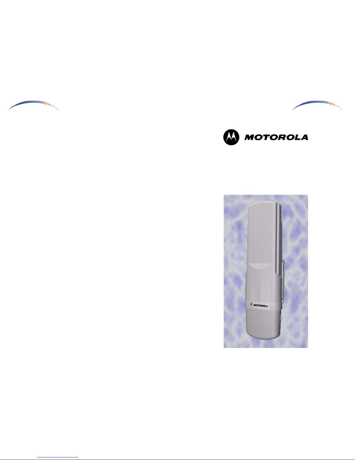
Congratulations!
You have purchased a Motorola CANOPY radio, the laest innovation in
high speed wireless networking. The Motorola CANOPY radio lets you
easily network at high speeds with no wiring.
- Network speeds of 10baseT.
- Small compact design
- No special set up on your PC.
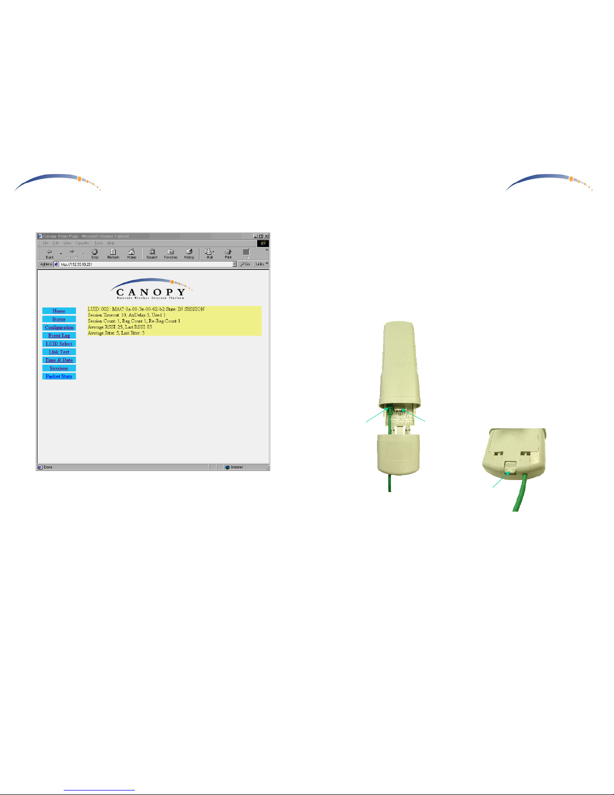
Getting to Know your Radio.
The base cover snaps off to
expose the RJ45 connector where
the Ethernet Cable will be
plugged in, as well as connection
LEDs used for dagnostics. The
base cover is released by
depressing a release lever on the
back of the base cover.
Ethernet
Cable
Base Cover
Release
Lever
Base Cover
Ethernet
Cable
Canopy AP
RJ45
Connector
Connection
LEDs
Base Cover
Page 4
C A N O P Y
Motorola Wireless Internet Platform
Page 4
Installing CANOPY
Mount from 1 to 6 CANOPY AP radios in a location where it is facing the
community to be served. Pick a location, pole, tower, rooftop or other
structure which provides an unobstructed view over the rooftops of the
surrounding buildings.
6 CANOPY AP radios on a pole will serve the surrounding community in
all directions.
Canopy AP Radios
Optimum Access Point height on
building or pole should minimally
clear the surrounding community
C A N O P Y
Motorola Wireless Internet Platform
Page 21
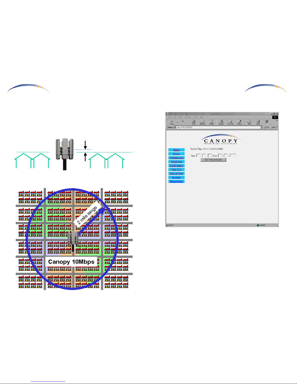
Time & Date
Each Canopy AP Unit can be configured with time & date. Further, the
entered Time & Date are automatically conveyed over the air to all
registered Canopy Subscriber Modules at the time of their next time of
registration
.
Time & Date are configured automatically in multiple Canopy AP Unit
sites where the Canopy AP Junction contains GPS.
Page 5
C A N O P Y
Motorola Wireless Internet Platform
Page 20
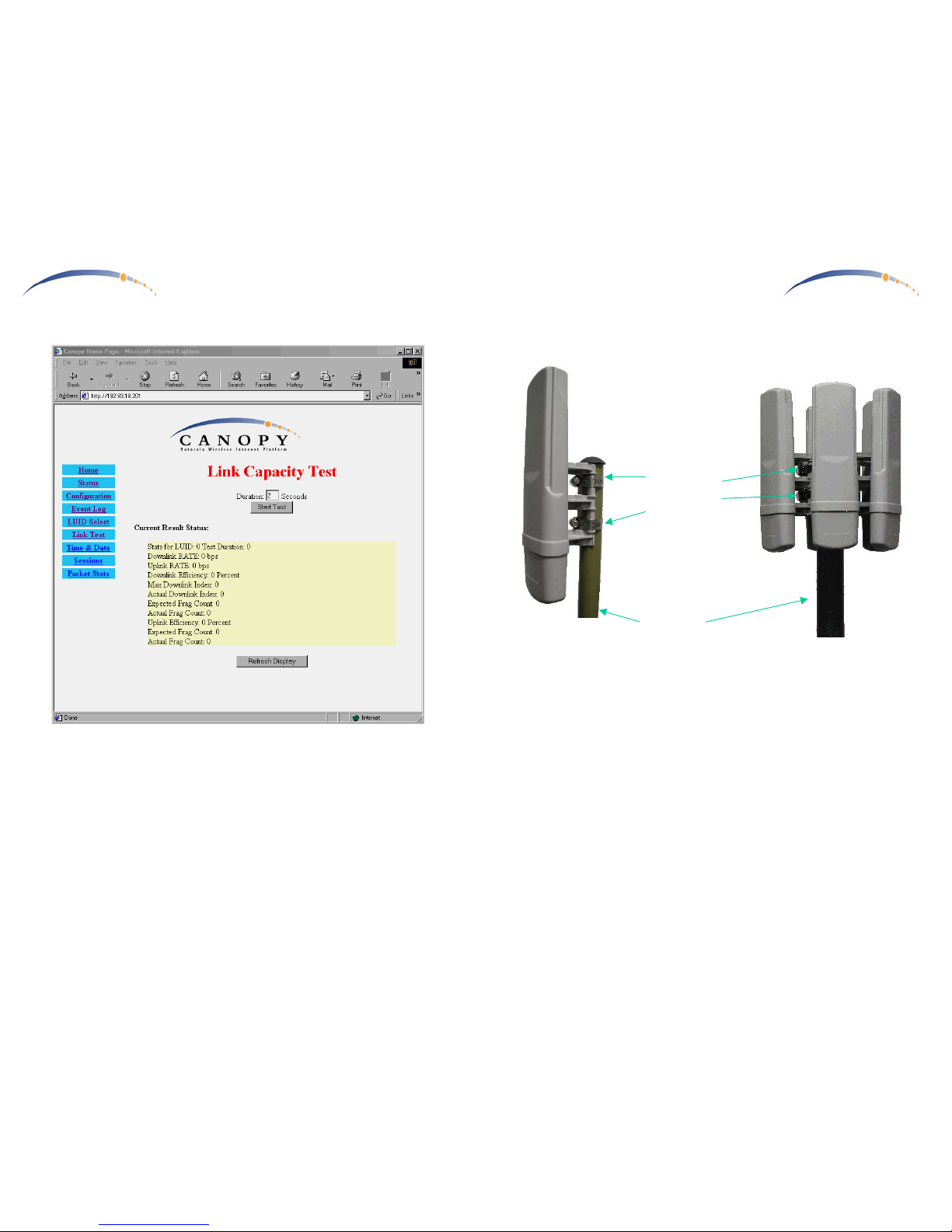
Link Test
In concert with the LUID select page, the radio link to the currently
selected Canopy SM Unit may be tested.
C A N O P Y
Motorola Wireless Internet Platform
Page 5
Mounting Your Canopy AP Units
- IMPORTANT NOTE: To comply with FCC RF exposure compliance
requirements, the following antenna installation and device operating
configurations must be satisfied. The Canopy AP Units must be
installed to provide a separation distance of at least 20cm from all
persons and must not be co-located or operating in conjunction with
any other antenna or transmitter. Installers must follow the Canopy
AP Unit installation instructions and transmitter operating conditions
for satisfying RF exposure compliance.
- The Canopy AP Units can be mounted in a variety of ways. Mounting
to a typical rooftop antenna mast is illustrated above as an example
using readily available stainless steel hose clamps or any equivalent
fasteners.
- The Canopy AP Units should be installed away from the service mast
and grounding of masts or brackets must be in accordance with
applicable requirements within section 810 of the National Electrical
Code (NEC).
1 Canopy AP
Radio
Stainless
Steel Hose
Clamps or
any Suitable
Equivalent
Typical
Antenna
Mast
6 Canopy AP Radios
Page 6
C A N O P Y
Motorola Wireless Internet Platform
Page 6
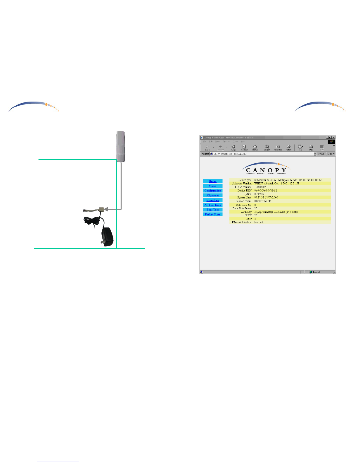
Connecting Your Single Canopy AP Unit
- Connect a CAT-5 Ethernet cable, such as Belden-E Datatwist ® 5E
1585LC, between the power adapter Ethernet patch and the RJ45
socket on the CANOPY AP.
- Plug the AC Adapter into an AC outlet. Plug the other side of the
power adapter’s Ethernet patch into a computer Ethernet port, hub,
router, or Ethernet switch.
- If connecting to a COMPUTER, use a Straight-Thru
Ethernet cable. If
connecting to a HUB, SWITCH, or ROUTER, use a Cross-Over
Ethernet cable.
AC Adapter
Ethernet
Cable
CANOPY
AP
Fixed Network
Access
Single CANOPY AP Site
C A N O P Y
Motorola Wireless Internet Platform
Page 19
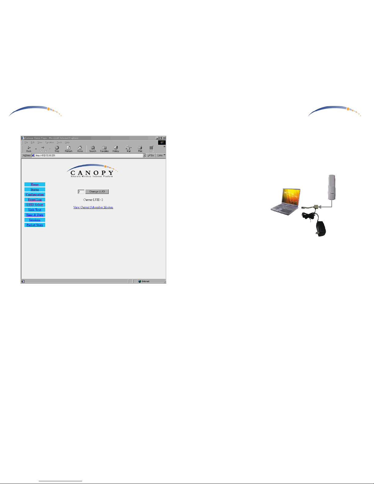
View Subscriber Module
In concert with the LUID Select page, the currently selected Canopy
Subscriber Module internal web pages can be accessed. Once selected,
other pages within the currently selected Subscriber Module can be
accessed. In this way, the system provider can examine, or even reconfigure registered Canopy Subscriber Modules.
Page 7
C A N O P Y
Motorola Wireless Internet Platform
Page 18
LUID Select
The user can select any of the registered Canopy SM Units currently
registered on this Canopy AP Unit for purposes of Link Testing or
accessing the Canopy SM Unit configuration web pages over the radio link.
C A N O P Y
Motorola Wireless Internet Platform
Page 7
Configuring your Canopy AP Units for a Multiple AP Unit Site
- All Canopy AP radios come pre-configured with the same default IP
address, 169.254.1.1. When mounting multiple Canopy AP radios
together at a site, they should first be reconfigured to different
individual IP addresses, or it will not be possible to individually
address them later.
- Use a Windows laptop or
computer configured for a
dynamic IP address.
Startup the laptop with no
Ethernet connection. This
automatically assigns a
compatible IP address to
the laptop in the 169.254
subnet.
- Connect a straight-thru
Ethernet cable from the
power-adapter Ethernet
patch to the RJ45 socket on the Canopy AP. Plug the AC adapter into
an AC outlet. Connect the other side of the power adapter’s Ethernet
patch into your PC Ethernet port.
- Using a web browser, go to the default URL (http://169.254.1.1) to
access the Canopy AP internal configuration web pages. Keeping a
permanent record, assign a sequentially consecutive address to each
Canopy AP unit.
Example:
1st Canopy AP Unit IP Address 192.168.1.2
2nd Canopy AP Unit IP Address 192.168.1.3
3rd Canopy AP Unit IP Address 192.168.1.4
4th Canopy AP Unit IP Address 192.168.1.5
5th Canopy AP Unit IP Address 192.168.1.6
6th Canopy AP Unit IP Address 192.168.1.7
- Changing the subnet assignment to valid IP addresses on your
network, and it is also recommended to begin IP assignments at 2.
- Once the Canopy AP Unit flash has been updated & the unit rebooted,
it may only be accessed thereafter by it’s new IP address.
AC Adapter
Ethernet
Cable
CANOPY
AP
Page 8
C A N O P Y
Motorola Wireless Internet Platform
Page 8
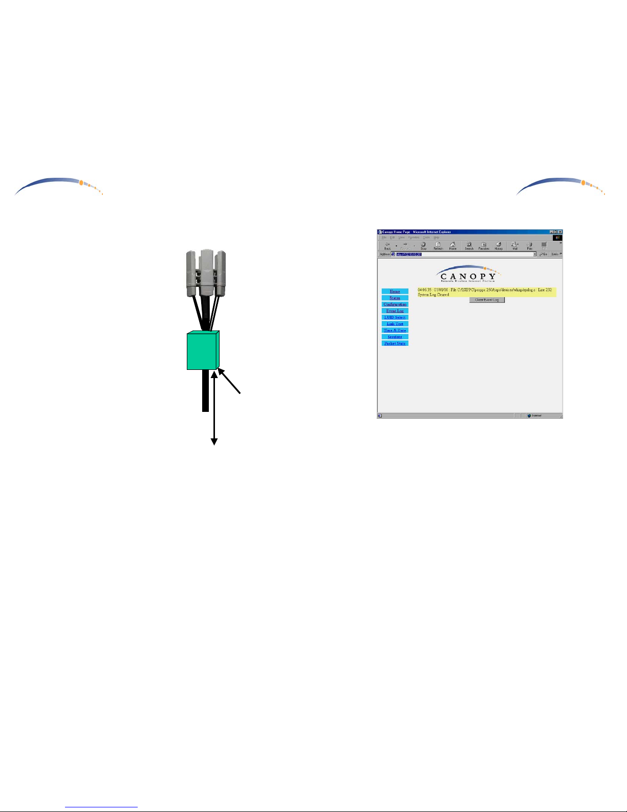
Connecting Your Multiple Canopy AP Units
- Once the Canopy AP Units have
been assigned unique IP addresses,
they are ready to be connected to the
Canopy AP Installation Kit. Mount
the Canopy AP Installation Kit near
the Canopy AP Units.
- Connect AC to the Canopy AP
Installation Kit.
- Connect a CAT-5 Ethernet cable,
such as Belden-E Datatwist ® 5E
1585LC, between the AP
Installation Kit and each CANOPY
AP Unit.
- Connect an RJ11c phone cable
between the AP Installation Kit
Sync connectors
and each
CANOPY AP Unit.
- Connect a CAT-5 Ethernet cable
between the AP Installation Kit and
a 100baseT network.
- Consult the AP Installation Kit user guide for more detailed
instructions.
Sync Input
One of the Sync connectors on the Canopy AP Junction is labeled
MASTER
. Make a permanent note of which Canopy AP Unit is connected
to the
MASTER Sync connector
.
- On the Canopy AP Unit internal configuration screen, select Sync AP
to Received Signal
to the
Sync Input
field for all connected to the
Canopy AP Junction. The GPS receiver within the Canopy AP
Junction will generate sync for all attached Canopy AP Units.
Multiple
Canopy AP
Installation
Kit
Ethernet
& Sync
Cables
6 Canopy
AP Radios
GPS Antenna
AC
100BaseT
Ethernet
C A N O P Y
Motorola Wireless Internet Platform
Page 17
Event Log
Information on Event Log is for tech support personnel only.
The user should not clear this data unless instructed to do so by tech
support personnel.
Page 9
C A N O P Y
Motorola Wireless Internet Platform
Page 16
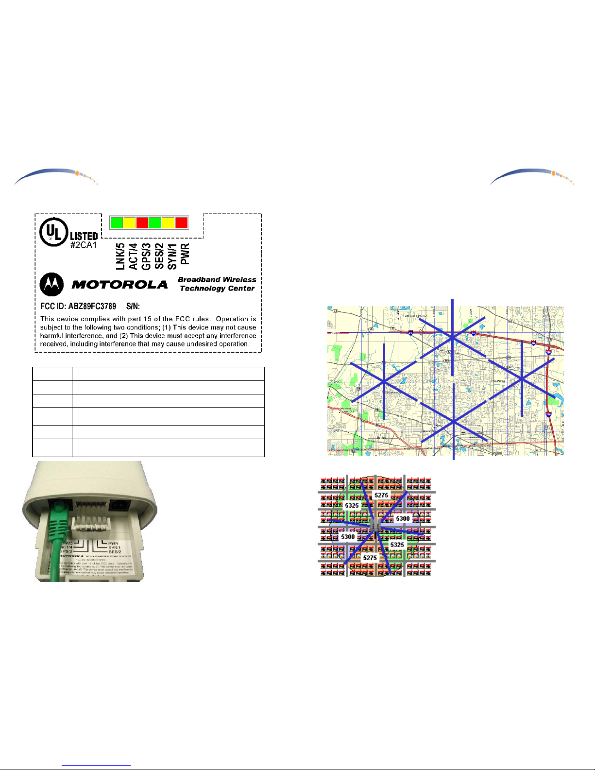
LED Display
In Normal Operating Mode the
LED indicators inside the Canopy
AP Unit provide various status
states. Each adjacent LED
employs a different colored LED
to help you distinguish one from
another. There are no color
coded meanings associated with
RED, YELLOW, or GREEN.
PWR
RED – Indicates the Canopy AP is powered
SYN/1
YELLOW – indicates AP Unit is operational
SES/2
GREEN – not used on the AP Unit
GPS/3
RED – indicates Sync input is active, if Sync Input is
configured as an input.
ACT/4
YELLOW – 10/100BaseT link activity, RX or TX
LNK/5
GREEN – 10/100BaseT link indicator
0A003E-XXXXXX
C A N O P Y
Motorola Wireless Internet Platform
Page 9
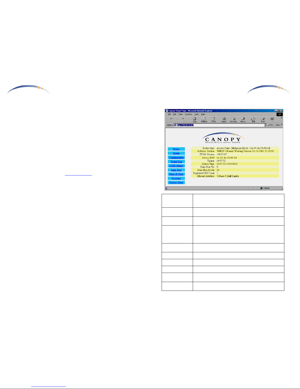
Planning Multiple Canopy AP Units
- Once the Canopy AP Units have been assigned unique IP addresses,
Sync Input, mounted, and connected to the Canopy AP Junctions, they
should be configured according to a frequency plan. Construct a
diagram of all the installed Canopy AP Units, and label each with the
assigned unique IP address and identify the Sync Master for each site
… preferably on a map overlay. This will become useful later when
providing directions for configuring Canopy Subscriber Modules.
Consider the example below depicting 24 Canopy AP Units at 4 sites.
192.168.1.3192.168.1.2
192.168.1.7
192.168.1.6
Master
192.168.1.5
192.168.1.4
192.168.1.13192.168.1.8
192.168.1.12
192.168.1.9
Master
192.168.1.10
192.168.1.11
192.168.1.17192.168.1.14
192.168.1.19
192.168.1.15
Master
192.168.1.16
192.168.1.18
192.168.1.25192.168.1.20
192.168.1.24
192.168.1.21
Master
192.168.1.22
192.168.1.23
- Using the configured IP addresses,
go to the configuration tab on the
internal web pages for each Canopy
AP Unit.
- Select an RF frequency for each
Canopy AP Unit based on it’s
direction / orientation using the
example guide shown at the left.
Units should be assigned different
frequencies in each adjacent cell,
while cells pointed in opposite
directions may use the same frequency.
Page 10
C A N O P Y
Motorola Wireless Internet Platform
Page 10
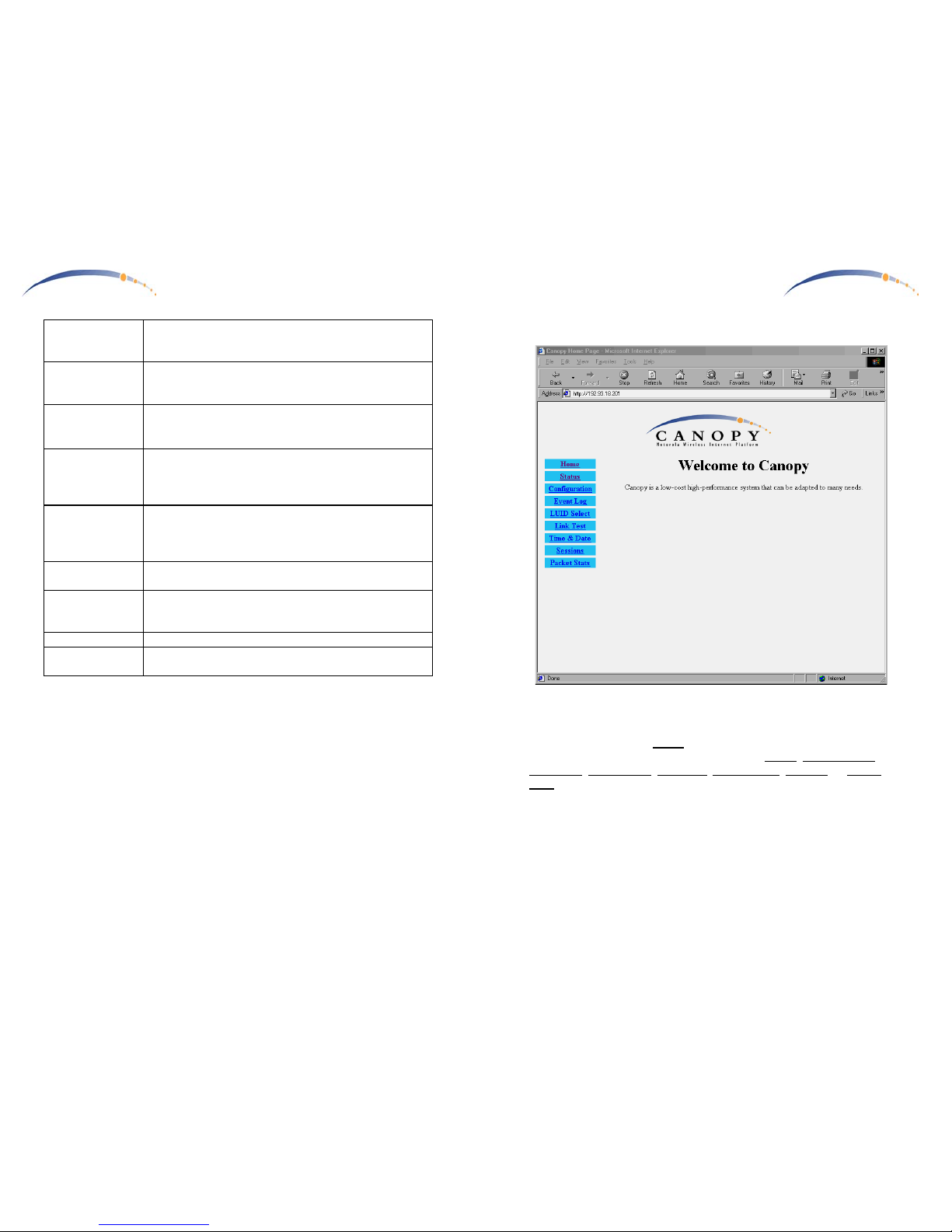
Accessing your Canopy AP Unit Configuration
A PC for accessing your Canopy AP Unit configuration does not require
any special setup beyond proper installation of Ethernet interface device,
drivers, and TCP/IP protocol.
Configuring the CANOPY AP Unit
During normal operation, the Canopy AP Unit provides a variety of status
& diagnostic information should this become necessary. The Canopy AP
Unit requires little configuration for operation and is delivered with default
operating parameters. As described earlier, in a multiple AP system,
reconfiguration of the Canopy AP Units is required to assign unique IP
address assignments, as well as coordinate Canopy AP Unit frequencies.
Open your web browser (such as Microsoft Internet Explorer) and enter the
Canopy AP Unit default URL (http://169.254.1.1
), or the URL with the
unique IP address assigned to a specific Canopy AP Unit. If the CANOPY
radio is powered and a proper network connection exists to your computer,
you will see the CANOPY AP Unit status page open in your web browser.
These web pages are within the CANOPY AP Unit, and no connection to
the Internet is required. Various web pages within the CANOPY AP Unit
can be selected from the choices on the left.
C A N O P Y
Motorola Wireless Internet Platform
Page 15
Status
Device type
should read Access Point – Multipoint Mode. Any other
label indicates an inappropriate preconfiguration of the
CANOPY AP Unit
Software Version
should be noted in the event you have technical difficulties
and need to contact technical support
FPGA Version
should be noted in the event you have technical difficulties
and need to contact technical support
Device ESN
is the Link Layer Ethernet Address assigned to your
CANOPY radio. Every CANOPY radio, Ethernet card, or
Network Interface Card (NIC) will have a unique number
preconfigured
Uptime
is the length of time your CANOPY radio has been
operating since power was last applied
System Time
is the time set by the wireless service provider
Data Slots Up
This information is for use of technical support
Data Slots Down
This information is for use of technical support
Registered SM
Count
The number of Canopy SM Units currently registered with
this Canopy AP Unit
Ethernet Interface
10/100 Base T, either half or full Duplex
This information is for use of technical support
Page 11
C A N O P Y
Motorola Wireless Internet Platform
Page 14
Lan1 IP
is preconfigured to the address
169.254.1.1
. In multiple AP
systems these should be changed to insure each Canopy AP
is assigned a unique IP address.
Lan1 Subnet Mask
is preconfigured to the value
255.255.0.0
for all Canopy AP
Units. Change this as appropriate when changing the Lan1
IP address.
Default Gateway
is preconfigured to the address
169.254.0.0
for all Canopy
AP Units. Change this as appropriate for your network
gateway.
Provider ID
All Canopy Units (AP & SM) in a system should be
configured with a unique provider ID which will permit all
radio messages between Canopy Units of another system to
be ignored.
Sector ID
A number may be entered into this field which is conveyed
to all registering Canopy SM Units under the heading
Sector ID. It may be useful to assign sequential sector IDs
to each Canopy AP Unit in multiple AP Unit sites.
Max Range
is preconfigured to 2 miles, and establishes the maximum
Canopy SM Unit range which will be allowed to register.
Update Flash
overwrites configuration previously saved to the CANOPY
radio. Changes will not take effect until the radio is powercycled or rebooted.
Reboot
Initiates a radio reboot.
Clear Changes
Re-displays current configuration of CANOPY configuration.
C A N O P Y
Motorola Wireless Internet Platform
Page 11
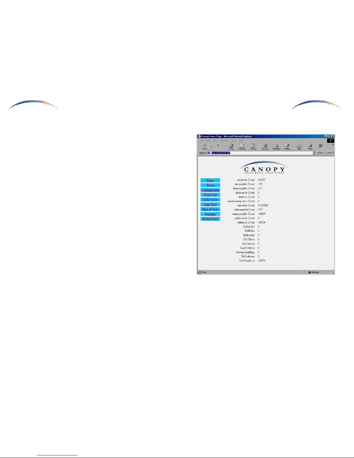
Home
This is the CANOPY AP
Home
page. You may select any of the other
pages within the CANOPY AP Unit, such as the Status
, Configuration,
Event Log
,
LUID Select, Link Test, Time & Date, Sessions
, or
Packet
Stats
.
Page 12
C A N O P Y
Motorola Wireless Internet Platform
Page 12
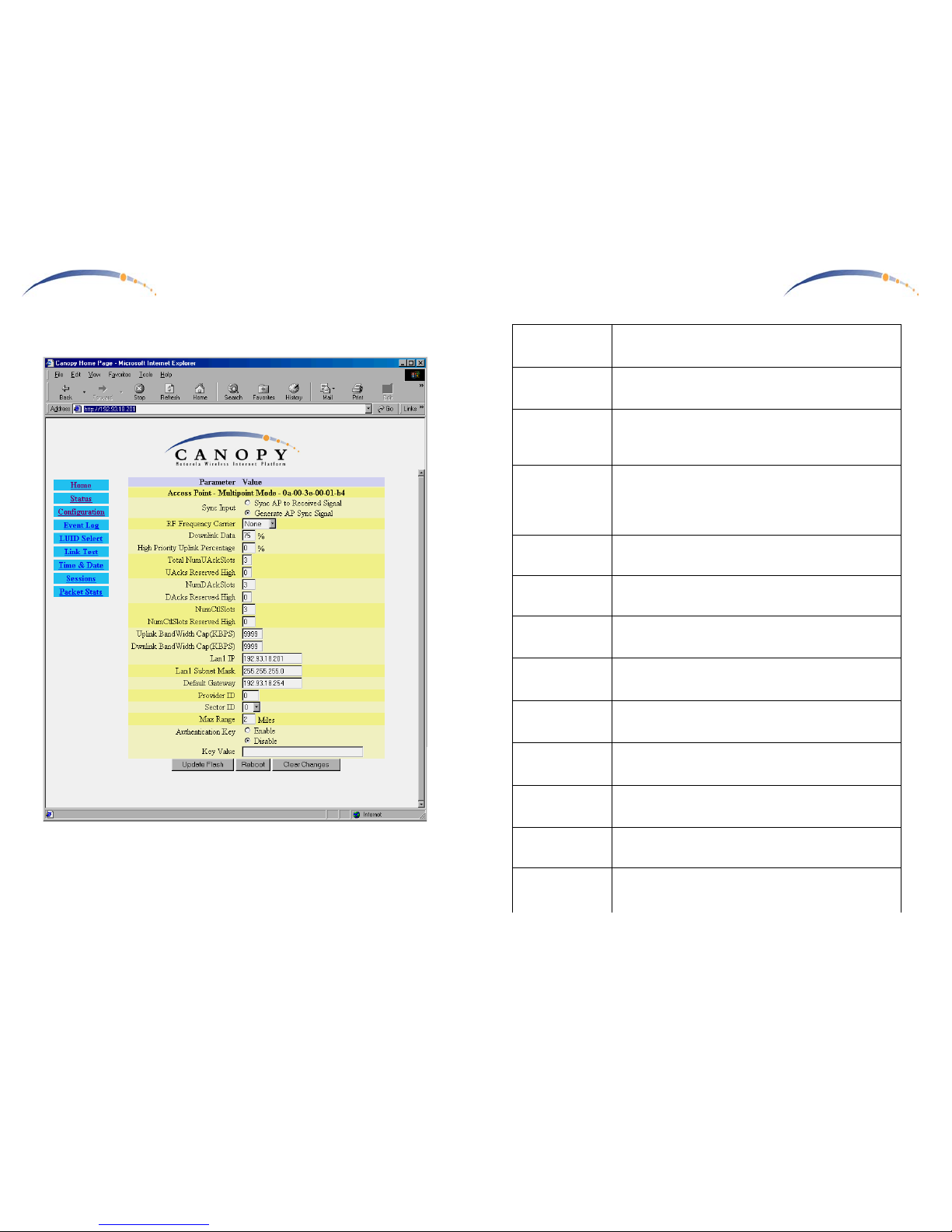
Configuration
Use this page to configure operating parameters for the Canopy AP Unit.
Sync Input, RF Frequency, and Lan1 IP Address will require
reconfiguration for multiple AP Unit Sites.
C A N O P Y
Motorola Wireless Internet Platform
Page 13
Device type
The second line should read
Access Point – Multipoint
Mode. Any other label indicates an inappropriate
preconfiguration of the CANOPY radio
Sync Input
Default is
Generate AP Sync Signal
. In multiple AP sites,
all APs should be set to Sync AP to Received Signal when
fed from the Canopy AP Junction.
RF Frequency
Carrier
Select the RF frequency for this Canopy AP Unit. The RF
frequency for all Canopy AP Units should be coordinated
to insure that adjacent cells operate on different
frequencies.
Downlink Data
Preallocate a division of the total bandwidth between
downlink (to the subscribers) and uplink (from the
subscribers). Typical web-browsing applications typically
are served best by more bandwidth allocated to downlink.
The default value is 75%.
High Priority
Uplink Percentage
is preconfigured to 0. This value permits establishing a
portion of uplink bandwidth for VoIP services.
Total
NumUAckSlots
is preconfigured to 3. This value permits tuning of the
number of slots per frame for Uplink Acknowledgements.
Uacks Reserved
High
is preconfigured to 0. This value permits tuning of the
number of slots per frame for Uplink Acknowledgements
for VoIP services.
NumD AckSlots
is preconfigured to 3. This value permits tuning of the
number of slots per frame for Downlink
Acknowledgements.
DAcksReserved
High
is preconfigured to 0. This value permits tuning of the
number of slots per frame for Downlink
Acknowledgements for VoIP services.
NumCtlSlots
is preconfigured to 3. This value permits tuning of the
number of contention slots per frame based on the number
of registered SM users.
NumCtlSlots
Reserved High
is preconfigured to 0. This value permits tuning of the
number of contention slots per frame for VoIP services
based on the number of registered SM users.
Uplink BandWidth
Cap (KBPS)
is preconfigured to 9999. This value permits creating a per
SM user capacity for Uplink data.
Dwnlink
BandWidth Cap
(KBPS)
is preconfigured to 9999. This value permits creating a per
SM user capacity for Uplink data.
Page 13
C A N O P Y
Motorola Wireless Internet Platform
Page 12
Specifications
Operating Frequency Range
U-NII Mid band 5.745 to 5.805 GHz
Access Method TDD/TDMA
Data Rate 10 Mbps
Modulation Type High Index BFSK/4FSK
(Optimized for interference rejection)
Carrier to Interference (C/I) 3dB Ber 1*10
-4
Receiver Sensitivity -84dBm 1*10
-4
Error Floor Better than 10
-9
BER, unfaded
Operating Range (All Weather) Up to 2 miles with integrated antenna
Transmitter Power Meets FCC UNII ERP Limit
DC Power 24 VDC @ 0.3 Amp (active state)
Interface 10 Base-T, RJ45
Rate auto negotiated (802.3 compliant)
Protocols Used by CANOPY IPV4, UDP, TCP, ICMP, Telnet,
HTTP, FTP, SNMP
Protocols Supported by CANOPY Switched Layer 2 Transport
with support for all common Ethernet
protocols including IPV6, NetBIOS,
DHCP, IPX, etc.
Software Upgrade Path Remotely downloaded into FLASH
via RF link
Network Management HTML, TELNET, SNMP
Environmental
Wind 190 km/hr
Humidity Relative Humidity 95% at 35°C
Temperature -30° to +55° C
Physical
Dimensions 11.75”H x 3.4”W
x 1.1”D (not counting mounting bracket)
x 3.4”D (including mounting bracket)
Weight Approx 1 lb, 0.5 kg
C A N O P Y
Motorola Wireless Internet Platform
Page 1
Getting Started with Motorola
CANOPYTM BH
REV 12/11/01
Page 14

C A N O P Y
Motorola Wireless Internet Platform
Page 2
Warranty Information
Motorola offers a warranty covering a period of 90 days from the date
of purchase by the retail customer. If a product is found defective during
the warranty period, Motorola will repair or replace the product with the
same or a similar model, which may be a reconditioned unit, without
charge for parts or labor.
C A N O P Y
Motorola Wireless Internet Platform
Page 11
Detailed Configuration & Operation
Each of your Canopy BH units operate logically as a Canopy AP or
Canopy SM. Detailed operational guide can be found within the associated
user guides:
•
Canopy AP User Guide
•
Canopy AP User Guide
Where an AP Installation kit is used to connect, power, & synchronize a
Canopy BH-AP, detailed connection & setup can be found within the
associated user guide:
•
Canopy AP Installation Kit
Page 15
C A N O P Y
Motorola Wireless Internet Platform
Page 10
Connecting Your Canopy BH Units
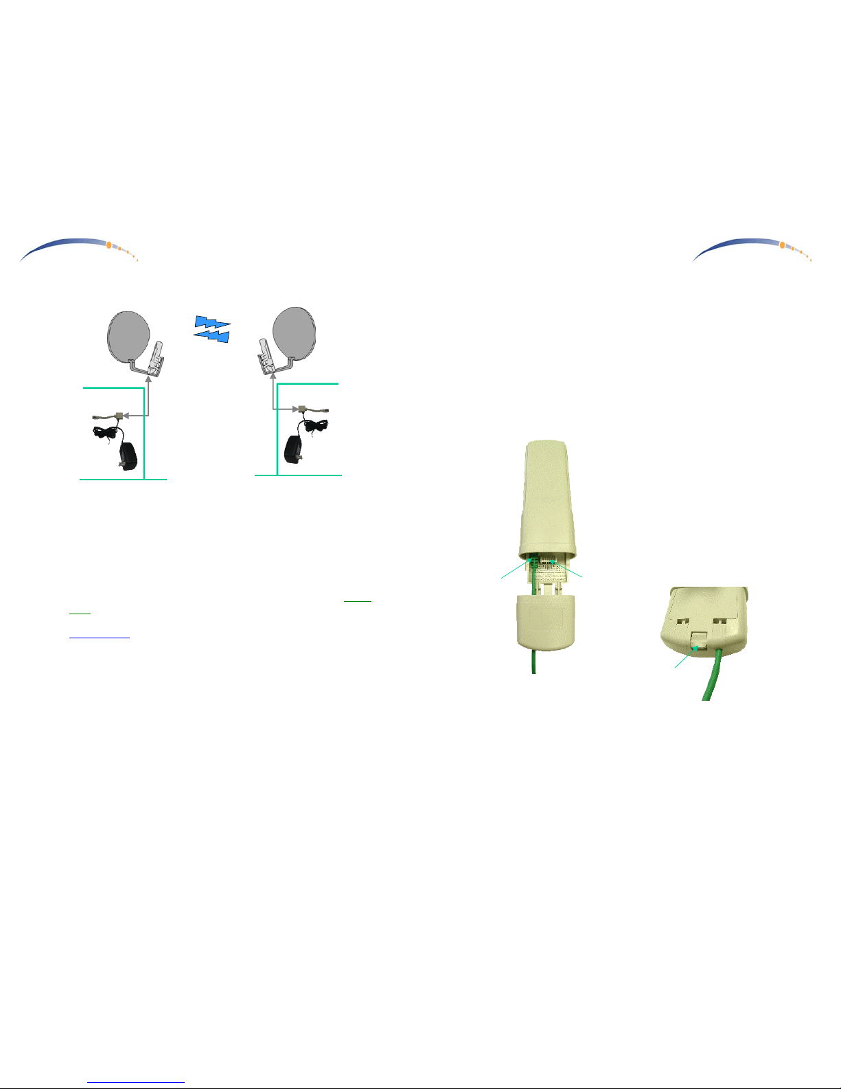
- Connect a CAT-5 Ethernet cable, such as Belden-E Datatwist ® 5E
1585LC, between the power adapter Ethernet patch and the RJ45
socket on the CANOPY BH.
- Plug the AC Adapter into an AC outlet. Plug the other side of the
power adapter’s Ethernet patch into a computer Ethernet port, hub,
router, or Ethernet switch.
• The Canopy BH units are depicted in the diagram above using a Cross-
Over Ethernet cable, to connect to a Fixed Network such as a HUB,
SWITCH, or ROUTER. If connecting to a COMPUTER, use a
Straight-Thru
Ethernet cable.
• Although Ethernet straight-through or crossover cables minimally
connect pins 1,2,3, & 6, insure that your Ethernet cable passes through
all connections (pins 4, 5, 7, & 8 convey power up to your Canopy
radio).
If one side or the other employs a Canopy AP Installation Kit, power is
provided without the need for an AC Adapter … however, the Ethernet
cable should be straight (not cross-over) to the Canopy BH unit because the
AP Installation Kit provides internal cross-over patches for all connected
Canopy AP units.
AC Adapter
Ethernet
Crossover
Cable
Fixed Network
Access
CANOPY
BH
CANOPY
BH
AC Adapter
Ethernet
Crossover
Cable
Fixed Network
Access
C A N O P Y
Motorola Wireless Internet Platform
Page 3
Congratulations!
You have purchased a Motorola CANOPY backhaul radio, the latest
innovation in high speed wireless networking. The Motorola CANOPY
radio lets you easily network at high speeds with no wiring.
- Network speeds of 20Mbps.
- Small compact design.
- Transparent 100baseT networking.
Getting to Know your Radio.
The base cover snaps off to
expose the RJ45 connector where
the Ethernet Cable will be
plugged in, as well as connection
LEDs used for dagnostics. The
base cover is released by
depressing a release lever on the
back of the base cover.
Ethernet
Cable
Base Cover
Release
Lever
Base Cover
Ethernet
Cable
Canopy AP
RJ45
Connector
Connection
LEDs
Base Cover
Page 16
C A N O P Y
Motorola Wireless Internet Platform
Page 4
Installing CANOPY BH
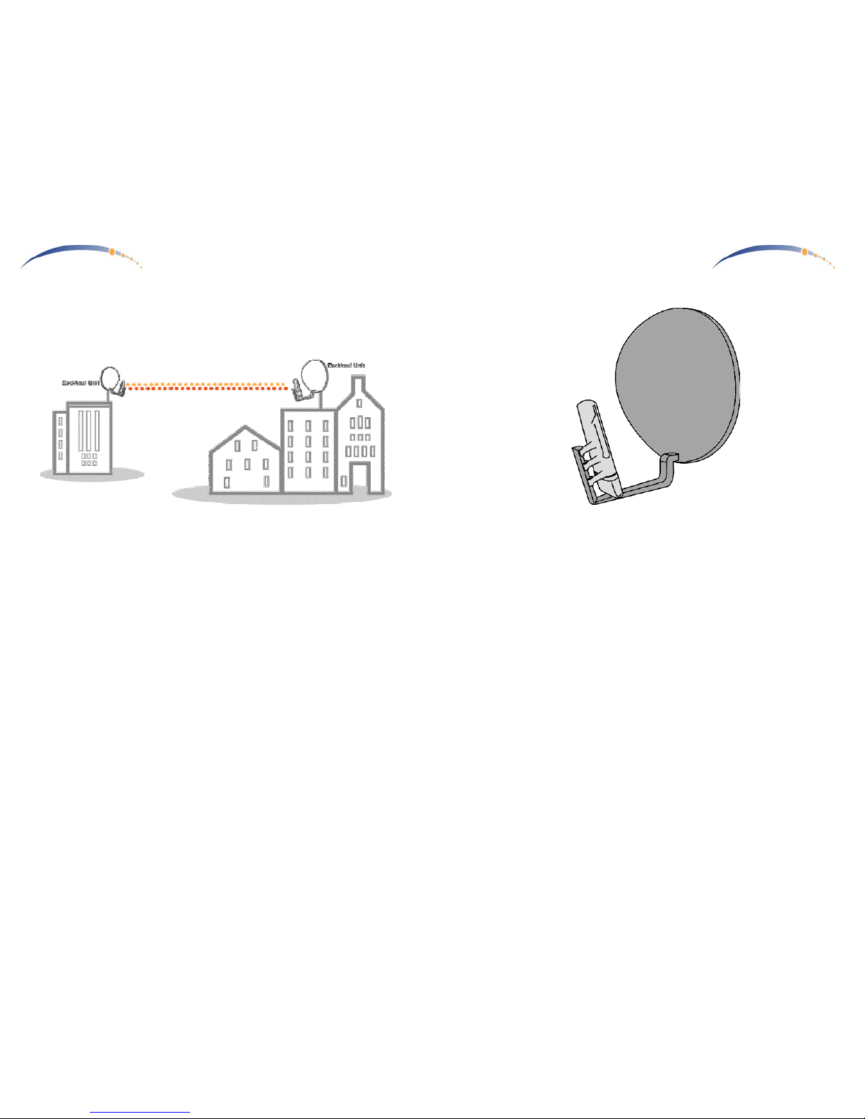
Mount the Canopy BH radios on any structures which will provide the pair
of radios a clear unobstructed view.
The Canopy BH units are configured as a pair with one of the units
designated as AP and one of the units designated as SM. Carefully align
both the AP unit and SM unit to point at each other. If the distance is far
enough that the target location is not visible, plan the direction using a map
and align the units carefully with a compass. Install and power the AP unit
first. Then when installing the SM location, the built-in alignment mode
will be used to fine-tune the alignment and verify the link.
Either side of the Point-to-Point link can be the BH-AP Unit. If one of the
following conditions applies, select the BH-AP unit accordingly:
•
If one side of the Point-to-Point link is also intended to be the location
of a Canopy Access Point to reach Point-to-MultiPoint Subscriber
Modules, put the Canopy BH-AP unit on this side and connect it using
the Canopy AP Installation Kit along with the other Canopy AP units.
•
If there is no connection to a Canopy Point-to-Multipoint network (just
a dedicated link), but one site is co-located with multiple Canopy
Point-to-Point links in a star configuration, put the Canopy BH-AP unit
on the multiple Canopy BH site … and use a Canopy AP Installation
Kit.
•
If there is no connection to a Canopy Point-to-Multipoint network (just
a dedicated link) but the network is managed from one side, put the
Canopy BH-AP unit on the side that the network is normally managed
from.
C A N O P Y
Motorola Wireless Internet Platform
Page 9
Mounting Your Canopy BH Units
- IMPORTANT NOTE: To comply with FCC RF exposure compliance
requirements, the following antenna installation and device operating
configurations must be satisfied. The Canopy BH Units must be
installed to provide a separation distance of at least 1.5meters from all
persons and must not be co-located or operating in conjunction with
any other antenna or transmitter. Installers must follow the Canopy
BH Unit installation instructions and transmitter operating conditions
for satisfying RF exposure compliance.
- The Canopy BH Units can be mounted in a variety of ways. Mounting
to a typical rooftop antenna mast is illustrated above as an example
using the bracket built into the back of the reflector dish.
- The Canopy AP Units should be installed away from the service mast,
and grounding of masts or brackets must be in accordance with
applicable requirements within section 810 of the National Electrical
Code (NEC).
Page 17
C A N O P Y
Motorola Wireless Internet Platform
Page 8
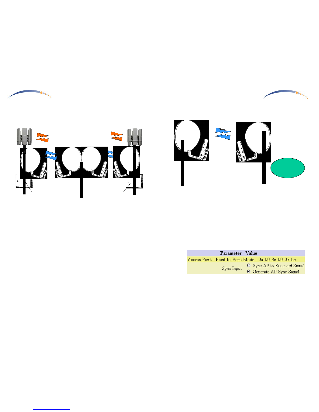
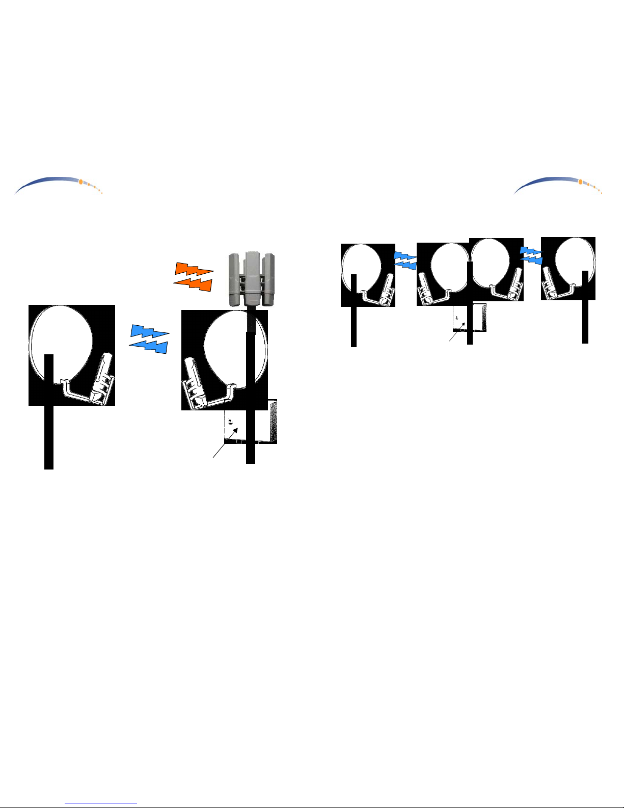
Canopy BH—Remote feed of multiple Canopy Access Points from a
common remote location
Where using Canopy BH to feed multiple Canopy Point-to-MultiPoint
Access Points from a remote location, all Canopy BH links can be synchronized from the Point-to-MultiPoint Access Points (each is equipped with a
Canopy AP Installation Kit). Here, the Canopy BH-SM units end up colocated, but operate synchronized, each synchronized by the Canopy BHAP units co-located at the Point-to-MultiPoint Access Points.
The Canopy BH-AP unit receives powered and GPS synchronization from
the Canopy AP Installation Kit. The Canopy BH-AP units must be
configured to “Sync AP to Received Signal”, and not “Generate AP Sync
Signal”.
Canopy
BH-SM
Pt-Pt
5.7GHz
Canopy
BH-AP
Pt-Pt
Canopy AP
Pt-MultiPt
Canopy AP
Installation
Kit
5.2GHz
Canopy
BH-AP
Pt-Pt
Canopy
BH-SM
Pt-Pt
Canopy AP
Pt-MultiPt
Canopy AP
Installation
Kit
5.2GHz
5.7GHz
C A N O P Y
Motorola Wireless Internet Platform
Page 5
5.7GHz
Canopy
BH-AP
Pt-Pt
Canopy
BH-SM
Pt-Pt
Network
Management
side
Canopy BH—Dedicated Link
This is a basic, simple, stand-alone dedicated link using Canopy BH.
Either side can be SM or AP. For convenience, the Canopy BH-AP unit
should be on the side of the link where normal management functions are
performed. The management side can directly access the internal web
pages of the Canopy BH-AP unit, and can access the Canopy BH-SM web
pages through the Canopy BH-AP unit.
Both Canopy BH units (SM & AP) both are powered by AC Adapters …
neither side uses a Canopy AP Installation Kit. Since there is no Canopy
AP Installation kit at either side, there is no GPS synchronization, and the
Canopy BH-AP unit must be configured to “Generate AP Sync Signal”,
and not “Sync AP to Received Signal”.
Page 18
C A N O P Y
Motorola Wireless Internet Platform
Page 6
Canopy BH—Remote Internet Feed to Canopy 5.2GHz Access Point
This is a basic use of Canopy BH to provide a remote Ethernet feed to a
Canopy 5.2GHz Pt-MultiPt Access Point. The Canopy Access Point
provides power and GPS for all Canopy units at the site, including the
Canopy BH-AP unit.
The Canopy BH-AP unit receives powered and GPS synchronization from
the Canopy AP Installation Kit. The Canopy BH-AP unit must be configured to “Sync AP to Received Signal”, and not “Generate AP Sync
Signal”.
Canopy
BH-AP
Pt-Pt
Canopy
BH-SM
Pt-Pt
5.7GHz
Canopy AP
Pt-MultiPt
Canopy AP
Installation
Kit
5.2GHz
C A N O P Y
Motorola Wireless Internet Platform
Page 7
Canopy BH—Co-Located Canopy BH units (multiple dedicated links)
Where multiple Canopy BH links share a site in common, a Canopy AP
Installation Kit can be employed to (a) power all the Canopy units at the
same site, and (b) provide synchronization. In this configuration, Canopy
BH-AP units should be placed at the same site, and the end-points of the
star configuration should be configured as Canopy BH-SM units.
The Canopy BH-AP unit receives powered and GPS synchronization from
the Canopy AP Installation Kit. The Canopy BH-AP unit must be configured to “Sync AP to Received Signal”, and not “Generate AP Sync
Signal”.
5.7GHz
Canopy
BH-AP
Pt-Pt
Canopy
BH-SM
Pt-Pt
Canopy
BH-AP
Pt-Pt
Canopy
BH-SM
Pt-Pt
5.7GHz
Canopy AP
Installation
Kit
Page 19

C A N O P Y
Motorola Wireless Internet Platform
Page 12
C A N O P Y
Motorola Wireless Internet Platform
Page 1
Getting Started with Motorola
CANOPYTM AP
INSTALLATION KIT
REV 10/31/01
Page 20

C A N O P Y
Motorola Wireless Internet Platform
Page 2
Warranty Information
Motorola offers a warranty covering a period of 90 days from the date
of purchase by the retail customer. If a product is found defective during
the warranty period, Motorola will repair or replace the product with the
same or a similar model, which may be a reconditioned unit, without
charge for parts or labor.
C A N O P Y
Motorola Wireless Internet Platform
Page 11
Page 21
C A N O P Y
Motorola Wireless Internet Platform
Page 10
Connecting the GPS Antenna
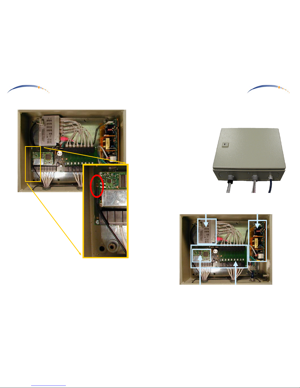
The GPS antenna cable plugs into a matching socket just below the left side
of the GPS receiver board. The GPS antenna at the other end of the GPS
antenna cable should be mounted above the Canopy AP Units on the
mounting mast, facing upwards towards the sky with an unobstructed view.
C A N O P Y
Motorola Wireless Internet Platform
Page 3
Congratulations!
You have purchased a Motorola CANOPY AP Installation Kit, an
accessory to the latest innovation in high speed wireless networking. The
Motorola CANOPY radio lets you easily network at high speeds with no
wiring.
- Network speeds of
10baseT.
- Small compact design
- No special set up on
your PC.
The Canopy AP Installation
Kit provides everything
necessary to get a multiple
Canopy AP Unit Access
Point operational.
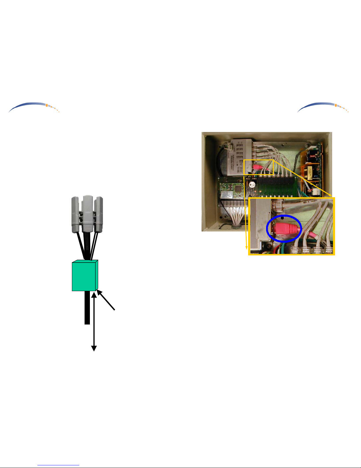
Getting to Know your Canopy AP Installation Kit.
Interconnect Board
Ethernet Switch
GPS
AC Supply
Page 22
C A N O P Y
Motorola Wireless Internet Platform
Page 4
Installing CANOPY AP Installation Kit
Mount the Canopy AP Installation Kit in a convenient location below the
Canopy AP Radio Units, on a multiple Canopy AP radio site. The
illustration below depicts a typical 6 Canopy AP Unit configuration on an
antenna mast or pole. In such a configuration, the Canopy AP Installation
Kit would be conveniently mounted on the same mast or pole below the
Canopy AP radio units.
Multiple
Canopy AP
Installation
Kit
Ethernet
& Sync
Cables
6 Canopy
AP Radios
GPS Antenna
AC
100BaseT
Ethernet
C A N O P Y
Motorola Wireless Internet Platform
Page 9
Connecting to the Network
The network should be connected to a 100baseT network source with a
CAT5 Ethernet Cable, as depicted by the pink cable in the photo above.
Page 23
C A N O P Y
Motorola Wireless Internet Platform
Page 8
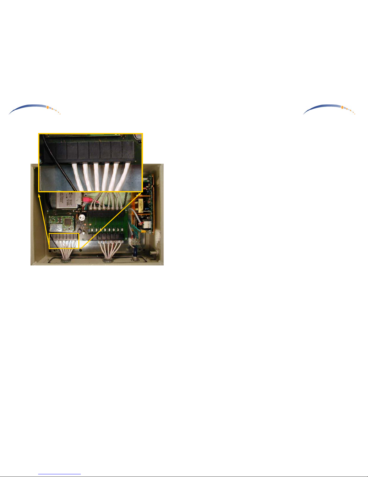
Connecting GPS Sync to the Canopy AP Units
The GPS Sync cables utilize RJ11 connectors (standard telephone size) and
connect to the matching RJ11 socket in each Canopy AP Unit at the site,
including backhaul units. A total of 8 sockets are available on the Canopy
AP Installation Kit, to accommodate a full 6 Canopy AP Units and 2
Canopy BH Units. Only 6 Canopy AP Units are depicted connected in the
photo above, with 2 unused sockets for Canopy BH Units.
C A N O P Y
Motorola Wireless Internet Platform
Page 5
Overview of Installation
- Once the Canopy AP Units have been assigned unique IP addresses,
they are ready to be connected to the Canopy AP Installation Kit
(details in the Canopy AP Unit User Guide). Mount the Canopy AP
Installation Kit near the Canopy AP Units.
1 Connect AC to the Canopy AP Installation Kit.
2 Connect a CAT-5 Ethernet cable, such as Belden-E Datatwist ® 5E
1585LC, between the AP Installation Kit and each CANOPY AP Unit.
3 Connect an RJ11c phone cable between the AP Installation Kit
Sync
connectors
and each CANOPY AP Unit.
4 Connect a CAT-5 Ethernet cable between the AP Installation Kit and a
100baseT network.
5 Mount the GPS Antenna facing upwards on top of the antenna mast,
and connect it to the AP Installation Kit GPS antenna port.
The following sections will take you through these steps one at a time.
Page 24
C A N O P Y
Motorola Wireless Internet Platform
Page 6
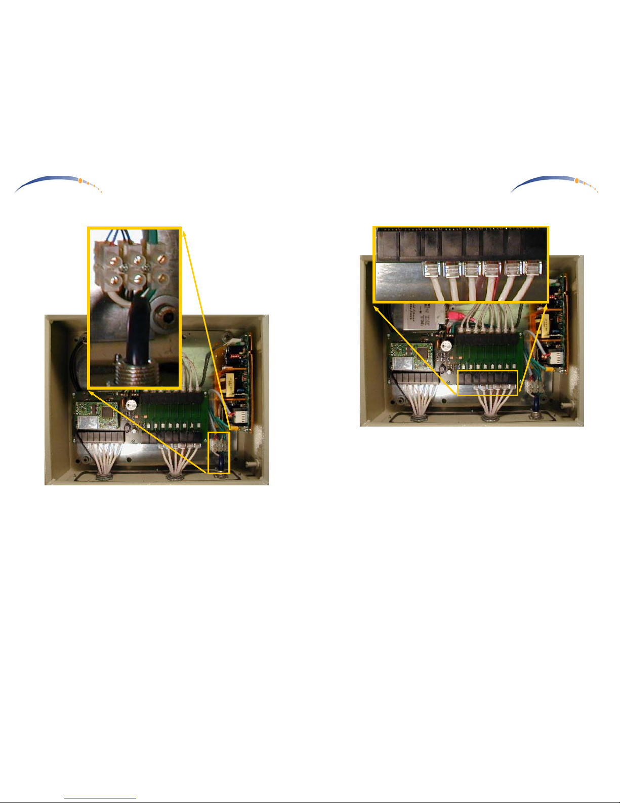
Connecting AC Power
Connect standard AC hot, common, & ground to the connection junction
just above the AC access opening in the housing.
C A N O P Y
Motorola Wireless Internet Platform
Page 7
Connecting Ethernet to the Canopy AP Units
The Ethernet cables utilize RJ45 connectors (standard Ethernet) and
connect to the matching RJ45 socket in each Canopy AP Unit at the site,
including backhaul units. A total of 8 sockets are available on the Canopy
AP Installation Kit, to accommodate a full 6 Canopy AP Units and 2
Canopy BH Units. Only 6 Canopy AP Units are depicted connected in the
photo above, with 2 unused sockets for Canopy BH Units.
 Loading...