


ASTRO® XTS 2500/XTS 2500I
Digital Portable Radio
Quick Reference Card
Product Safety and RF Exposure Compliance
Before using this product, read the operating instructions
for safe usage contained in the Product Safety and RF
Exposure booklet enclosed with your radio.
ATT ENTI ON!
This radio is restricted to occupational use only to satisfy
FCC RF energy exposure requirements. Before using this
product, read the RF energy awareness information and
operating instructions in the Product Safety and RF
Exposure booklet enclosed with your radio (Motorola
Publication part number 6881095C98) to ensure
compliance with RF energy exposure limits.
On/Off/
Volume Knob
Top Side
Button
_ _ _ _ _ _ _
PTT Button
Side Button 1
_ _ _ _ _ _ _
Side Button 2
_ _ _ _ _ _ _
Home Button
4-Way
Navigation
Button
3-Position
Rotary Switch
_ _ _ _ _ _
16-Position
Select Knob
Top Button
_ _ _ _ _ _ _
Speaker/Mic
Display
Menu Select
Buttons
App Button
(TMS Button)
Keypad
Write your radio’s programmed features on
the dotted lines.
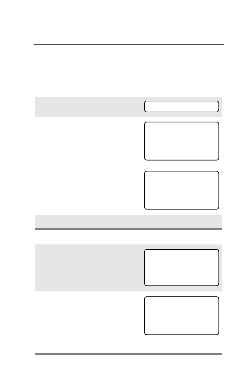
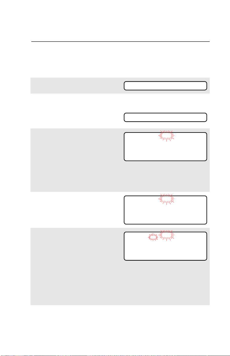
Select a Zone Using the Menu
1 Press U until
ZONE
2 Press D, E, or F directly below ZONE.
3 Press U until the zone you desire is shown
OR
Use the keypad directly to dial the zone
number.
4 Press h to confirm, or press PTT to transmit.
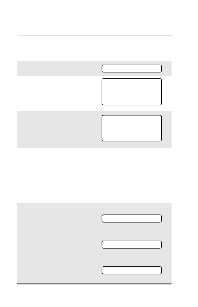
Select a Channel
Method 1: Using the Select Knob
After selecting the desired zone, turn the 16position Select Knob to the desired channel.
Method 2: Using the Menu
1 Press U until
2 Press D, E, or F directly below CHAN.
3 Press U until channel you desire is shown
4 Press h to confirm, or press PTT to transmit.
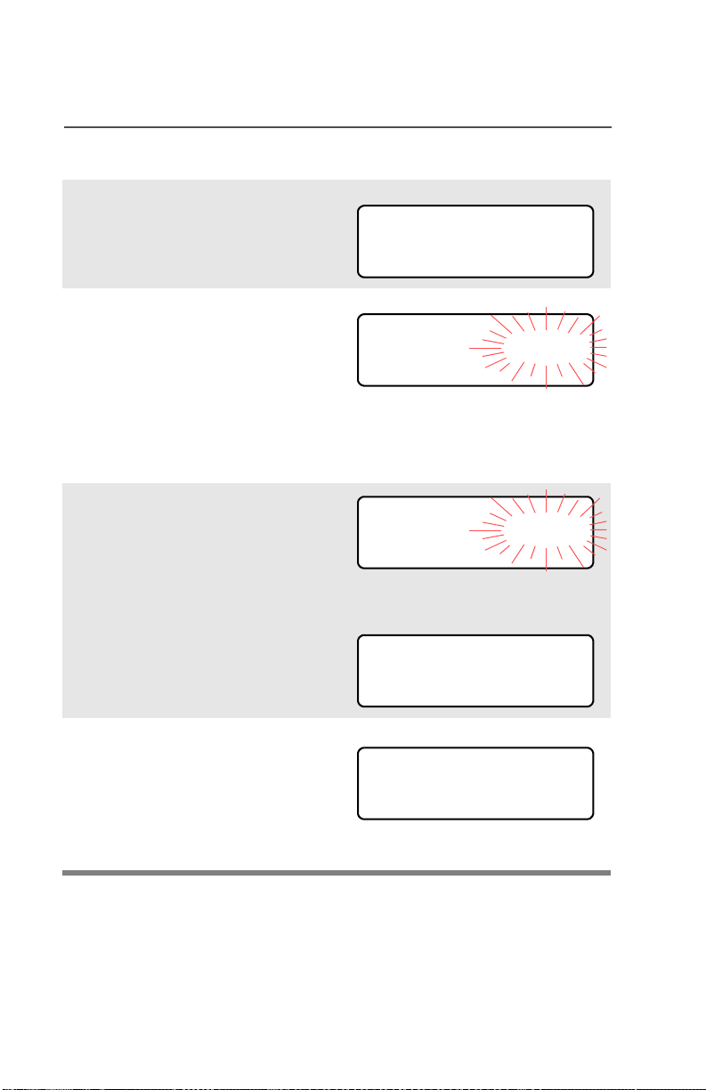
Send an Emergency Alarm
1 Radio on and press Emergency button. You
see red LED; you hear short, medium-pitched
tone.
2 Display shows .
3 When acknowledgment is received, you hear
four tones;alarm ends;radio exits emergency.
CHAN
EMERGENCY
Send Silent Emergency Alarm
1 Radio on and press Emergency button. You
see no LED; you hear no tone.
2 Press PTT.
3 Alarm continues until you exit by:
• Press and hold Emergency button for one
second.
OR
•Press PTT again.
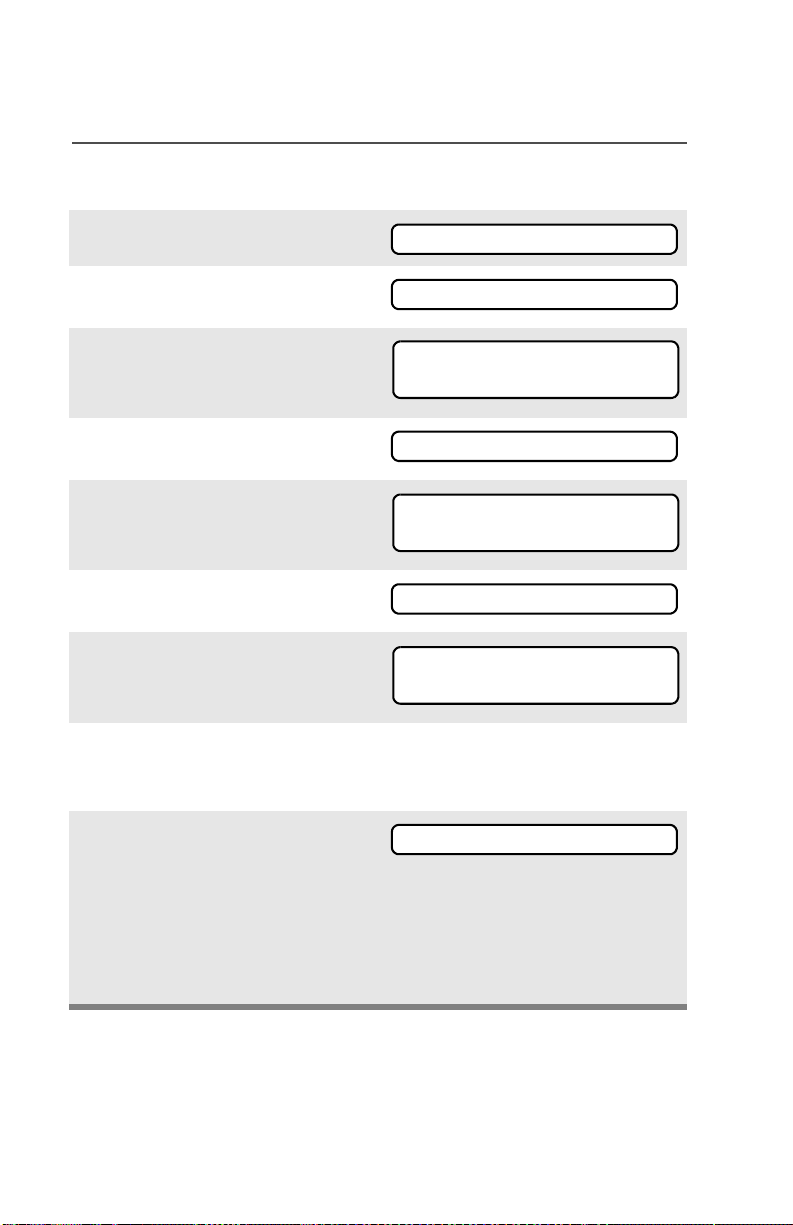
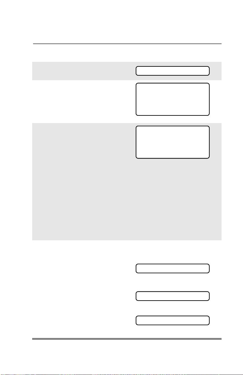
Answer a Phone Call
1 Phone-like ringing, LED blinks GREEN,
PHONE CALL and m are displayed.
2 Press Call Response button.
3 Press PTT button to talk; release to listen.
4 Press h to hang up.
Send a Phone Call
1 Press U until
PHON
2 Press D, E, or F directly below PHON.
3 Press U or V to scroll to phone number.
4 Press PTT (or Quick Access button, if
programmed) to talk, release to listen.

Display Status Symbols
Call Received. Receiving an individual call
m
View/Program Mode. The radio is in the view or
p
program mode; On Steady = view mode;
Blinking = program mode
p
Received Signal Strength Indication (RSSI).
s
Received signal strength for the current site
(trunking only). The more stripes in the symbol,
the stronger the signal.
Battery
b
• Conventional = Blinks when the battery is
low.
• Smart = The number of bars (0-3) shown
indicates the charge remaining in your
battery.
Note: Smart battery will be available at a
future date.
Talkaround. You are talking directly to another
r
radio or through a repeater;
On = direct;
Off = repeater
Monitor (Carrier Squelch). This channel is
C
being monitored.
Scan. The radio is scanning a scan list
T
User Login Indicator (IP Packet Data)
• On = User is associated with the radio;
• Off = User is not associated with the radio;
• Blinking = Registration with the server
failed.
Location Signal
• Off = Location feature disabled, or
insufficient battery power in location
accessory device;
• Blinking = Location feature enabled, but no
location signal available;
•On = Location feature enabled, and location
signal available.
Menu Entries (Use With Menu Navigation)
Entry Menu Selection Page
BATT *Smart Battery 19
CALL Private Call 58
CHAN Select a Channel 27
CLCK Edit Time and Date 76
DIR Repeater/Direct 64
KILL Radio Kill 65
MUTE Keypad Mute 35
NAME Text Select 47
Menu Navigation
U to find Menu Entry
D, or E, or F directly below
Menu Entry to select
Entry Menu Selection Page
NUM Number Select 45
PAGE Call Alert Page 60
PHON Phone 53
PROG Editing 45
PSWD Password 34
RPGM Reprogram Request 69
SCAN Scan On/Off 49
SITE Site Lock 73
STUN Radio Stun 66
TGRP Talkgroup Call 63
TMS Text Messaging 91
USER User Login 85
VIEW Viewing a List 43
ZONE Select a Zone 26
*Available at a future date.
V or U to scroll through sub-list
h to exit
D, or E, or F directly below
Menu Entry to select

ASTRO
®
XTS
Model 3
User Guide
TM
2500 & XTS
TM
2500I

ASTRO® XTS™ 2500 / XTS™ 2500I
Digital Portable Radio
Model III
User Guide
6816981H01-C
MOTOROLA, the Stylized M Logo, ASTRO, and CommPort are registered in
the U.S. Patent & Trademark Office. All other product or service names are
the property of their respective owners.
P25 radios contain technology patented by Digital Voice Systems, Inc.
© Motorola, Inc. 2005, 2006, 2007. All Rights Reserved. Printed in the U.S.A.
Motorola, Inc.
1301 E. Algonquin Rd.
Schaumburg, IL 60196-1078 U.S.A.

This declaration is applicable to your radio only if your radio is labeled
with the FCC logo shown below.
DECLARATION OF CONFORMITY
Per FCC CFR 47 Part 2 Section 2.1077(a)
Responsible Party
Name: Motorola, Inc.
Address: 1301 East Algonquin Road.
Schaumburg, IL 60196-1078, USA
Phone Number: 1-847-576-5000
Hereby declares that the product:
Model Name: XTS 2500 / XTS 2500I
conforms to the following regulations:
FCC Part 15, subpart B, section 15.107(a), 15.107(d) and section 15.109(a)
Class B Digital Device
As a personal computer peripheral, this device complies with Part 15 of the FCC
Rules. Operation is subject to the following two conditions:
1. this device may not cause harmful interference, and
2. this device must accept any interference received, including interference that
may cause undesired operation.
Note: This equipment has been tested and found to comply with the limits for a
Class B digital device, pursuant to part 15 of the FCC Rules. These limits are
designed to provide reasonable protection against harmful interference in a
residential installation. This equipment generates, uses and can radiate radio
frequency energy and, if not installed and used in accordance with the
instructions, may cause harmful interference to radio communications.
However, there is no guarantee that interference will not occur in a particular
installation.
If this equipment does cause harmful interference to radio or television reception,
which can be determined by turning the equipment off and on, the user is
encouraged to try to correct the interference by one or more of the following
measures:
• Reorient or relocate the receiving antenna.
• Increase the separation between the equipment and receiver.
• Connect the equipment into an outlet on a circuit different from that to which
the receiver is connected.
• Consult the dealer or an experienced radio/TV technician for help.
ii

Product Safety and RF Exposure Compliance
Before using this product, read the operating
instructions for safe usage contained in the Product
Safety and RF Exposure booklet enclosed with your
radio.
ATTENTION!
This radio is restricted to occupational use only to satisfy FCC
RF energy exposure requirements. Before using this product,
read the RF energy awareness information and operating
instructions in the Product Safety and RF Exposure booklet
enclosed with your radio (Motorola Publication part number
6881095C98) to ensure compliance with RF energy exposure
limits.
For a list of Motorola-approved antennas, batteries, and other
accessories, visit the following web site which lists approved
accessories: http://www.motorola.com/governmentandenterprise
Computer Software Copyrights
The Motorola products described in this manual may include
copyrighted Motorola computer programs stored in semiconductor
memories or other media. Laws in the United States and other
countries preserve for Motorola certain exclusive rights for
copyrighted computer programs, including, but not limited to, the
exclusive right to copy or reproduce in any form the copyrighted
computer program. Accordingly, any copyrighted Motorola computer
programs contained in the Motorola products described in this
manual may not be copied, reproduced, modified, reverseengineered, or distributed in any manner without the express written
permission of Motorola. Furthermore, the purchase of Motorola
products shall not be deemed to grant either directly or by implication,
estoppel, or otherwise, any license under the copyrights, patents or
patent applications of Motorola, except for the normal non-exclusive
license to use that arises by operation of law in the sale of a product.
iii

Documentation Copyrights
No duplication or distribution of this document or any portion thereof
shall take place without the express written permission of Motorola.
No part of this manual may be reproduced, distributed, or transmitted
in any form or by any means, electronic or mechanical, for any
purpose without the express written permission of Motorola.
Disclaimer
The information in this document is carefully examined, and is
believed to be entirely reliable. However, no responsibility is assumed
for inaccuracies. Furthermore, Motorola reserves the right to make
changes to any products herein to improve readability, function, or
design. Motorola does not assume any liability arising out of the
applications or use of any product or circuit described herein; nor
does it cover any license under its patent rights, nor the rights of
others.
iv

Important Rebanding Information
This radio supports the new FCC 800 MHz Public Safety frequency
band definition. The FCC has reorganized the 800 MHz band to
reduce particular types of interference impacting public safety radio
systems by moving the NPSPAC transmit frequencies from
821-824MHz to the 806-809 MHz area.This change consolidates
700 MHz and 800 MHz public safety transmit frequencies into a
single contiguous block of spectrum with a greater degree of
separation from cellular and Enhanced SMR frequencies.
This separation should limit any harmful out-of-band emission and
receiver intermodulations.
Note: In accordance with the FCC 800 MHz rebanding Report and
Order (Docket 02-55), Motorola has offered rebanding
replacement products to allow 800 MHz licensees to comply
with the new band plan. These rebanding products are part of
Motorola's current ASTRO Digital XTS and XTL product
portfolio and are denoted by an RB at the end of the product
title. These products offer all of the features of the current
products but have the channel capacity and call list sizes
equivalent to the MTS 2000 and MCS 2000 products.
ASTRO XTS 2500 / XTS 2500I Model III v

Notes
vi

Contents
Declaration of Conformity .................................................................. ii
Product Safety and RF Exposure Compliance .................................iii
Computer Software Copyrights .........................................................iii
Documentation Copyrights ............................................................... iv
Disclaimer ........................................................................................ iv
Important Rebanding Information ...................................................... v
General Radio Operation . . . . . . . . . . . . . . . . . . . . . . . 1
Notations Used in This Manual ......................................................... 1
XTS 2500 / XTS 2500I Model III Radio ............................................. 2
Physical Features of the XTS 2500 / XTS 2500I Model III Radio ..... 3
Programmable Features ................................................................... 4
Display .............................................................................................. 5
Backlight ........................................................................................... 5
Status Symbols ................................................................................. 6
Menu Entry (Softkey) ........................................................................ 8
Menu Select Buttons ......................................................................... 8
Menu Entry Features .................................................................. 9
Home Button (h) ............................................................................ 10
App Button (TMS Feature Button) .................................................. 10
4-Way Navigation Button (o) ......................................................... 10
Keypad ............................................................................................ 11
LED Indicators ................................................................................ 12
Alert Tones ...................................................................................... 13
Standard Accessories ..................................................................... 17
Battery ...................................................................................... 17
Smart Battery Condition ........................................................... 19
Antenna .................................................................................... 20
Belt Clip .................................................................................... 21
Universal Connector Cover ............................................................. 22
Remote Speaker Microphone Adapter ............................................ 23
Radio On and Off ............................................................................ 25
Turn the Radio On .................................................................... 25
Turn the Radio Off .................................................................... 25
Zones and Channels ....................................................................... 26
Select a Zone ........................................................................... 26
Select a Channel ...................................................................... 27
Receive / Transmit .......................................................................... 29
Without Using the Volume Set and Monitor Buttons ................ 29
ASTRO XTS 2500 / XTS 2500I Model III vii

Contents
Use Preprogrammed Volume Set Button ..................................30
Use the Preprogrammed Monitor Button ..................................31
Conventional Mode Operation ..................................................32
Common Radio Features . . . . . . . . . . . . . . . . . . . . . . 33
Radio Lock .......................................................................................33
Unlock Your Radio ....................................................................33
Change Your Password ............................................................34
Mute or Unmute Keypad Tones .......................................................35
Use the Menu ............................................................................35
Using the Preprogrammed Side Button ....................................35
Conventional Squelch Options ........................................................36
Analog Squelch .........................................................................36
Digital Squelch ..........................................................................36
PL Defeat .........................................................................................37
Time-out Timer ................................................................................38
Emergency ......................................................................................39
Send an Emergency Alarm .......................................................39
Send an Emergency Call ..........................................................40
Send a Silent Emergency Alarm ...............................................41
Emergency Keep-Alive .............................................................42
Lists .................................................................................................43
View a List .................................................................................43
Scan List Empty ........................................................................44
Edit a Call, Page, or Phone List Number .........................................45
Use the Menu ............................................................................45
Edit a Call, Page, or Phone List Name ............................................47
Use the Menu ............................................................................47
Scan ................................................................................................49
Turn Scan On and Off ...............................................................49
Delete a Nuisance Channel ......................................................51
Conventional Scan Only ...........................................................52
Telephone Calls (Trunking Only) .....................................................53
Answer a Phone Call ................................................................53
Make a Phone Call ....................................................................54
Phone Call Display and Alert Prompts ......................................56
Private Calls (Trunking Only) ...........................................................57
Answer a Private Call ................................................................57
Make a Private Call ...................................................................58
viii

Contents
Call Alert Paging ............................................................................. 60
Answer a Call Alert Page .......................................................... 60
Make a Call Alert ...................................................................... 61
Conventional Talkgroup Calls
(Conventional Operation Only) ....................................................... 63
Select Talkgroup ....................................................................... 63
Repeater or Direct Operation .......................................................... 64
Select Repeater or Direct Operation ........................................ 64
Special Radio Features. . . . . . . . . . . . . . . . . . . . . . . . 65
Radio Kill ......................................................................................... 65
Remote Kill ............................................................................... 65
Direct Kill .................................................................................. 65
Radio Stun ...................................................................................... 66
PTT ID ............................................................................................. 67
Receive ..................................................................................... 67
Transmit .................................................................................... 67
View Your Radio’s ID Number .................................................. 68
Dynamic Regrouping (Trunking Only) ............................................. 69
Reprogram Request (ASTRO 25 Trunking Only) ..................... 69
Select Enable / Disable ............................................................ 71
Trunking System Controls ............................................................... 72
Failsoft ...................................................................................... 72
Out-of-Range ............................................................................ 72
Site Lock ................................................................................... 73
Site Trunking ............................................................................ 74
Site View and Change .............................................................. 74
Time and Date ................................................................................. 76
Edit Time and Date ................................................................... 76
Outdoor Location (using GPS) ........................................................ 78
Access the Location feature ..................................................... 78
GPS Enabled ............................................................................ 80
ARS User Login and Text Messaging Features . . . . 83
Automatic Registration Service (ARS) ............................................ 83
Selecting or Changing ARS Mode ............................................ 83
ARS User Login Feature ................................................................. 85
Accessing the User Login Feature ........................................... 85
To Login as a User ................................................................... 86
Selecting a Predefined Username ............................................ 90
ASTRO XTS 2500 / XTS 2500I Model III ix

Contents
Text Messaging ................................................................................91
Accessing TMS Feature ............................................................91
Receive a Message ..................................................................96
To View Message from the Inbox. ............................................96
Compose a New Text Message ................................................97
..................................................................................................98
Send a Predefined Message ...................................................100
Edit a Quick Text Message .....................................................101
Reply to a Received Message ................................................102
Delete a Message ...................................................................102
To Access the Draft Folder .....................................................103
To Access the Sent Folder ......................................................104
Helpful Tips . . . . . . . . . . . . . . . . . . . . . . . . . . . . . . . . 105
Radio Care ....................................................................................105
Cleaning ..................................................................................105
Handling ..................................................................................105
Service ...........................................................................................105
Battery ...........................................................................................106
Battery Life ..............................................................................106
Charging the Battery ...............................................................106
Battery Recycling and Disposal .....................................................108
Antenna .........................................................................................109
Radio Operating Frequencies .................................................109
Accessories. . . . . . . . . . . . . . . . . . . . . . . . . . . . . . . . 111
Antennas ....................................................................................... 111
Batteries ........................................................................................112
Carry Accessories .........................................................................112
Belt Clips .................................................................................112
Body-Worn ..............................................................................112
Chargers ........................................................................................113
Enhanced and Multi-Unit Line Cords ......................................113
Microphones, Remote Speaker ..................................................... 114
Surveillance Accessories ............................................................... 115
Adapters and Adapter Cable ...................................................115
CommPort® Integrated Microphone/Receivers .......................115
Earpieces ................................................................................115
Headsets and Headset Accessories .......................................117
Radio Interface Modules for Ear Microphones ........................117
x

Contents
Switches ........................................................................................ 117
Appendix: Maritime Radio Use in the VHF Frequency
Range . . . . . . . . . . . . . . . . . . . . . . . . . . . . . . . . . . . . . 119
Special Channel Assignments ....................................................... 119
Emergency Channel ............................................................... 119
Non-Commercial Call Channel ............................................... 120
Operating Frequency Requirements ............................................. 120
Glossary. . . . . . . . . . . . . . . . . . . . . . . . . . . . . . . . . . . 123
Commercial Warranty . . . . . . . . . . . . . . . . . . . . . . . . 127
Index. . . . . . . . . . . . . . . . . . . . . . . . . . . . . . . . . . . . . . 133
ASTRO XTS 2500 / XTS 2500I Model III xi

Table 1: Channel Map
Use the chart below to map the channels (Cx) and zones (Zx) for your radio.
Z1 Z2 Z3 Z4 Z5 Z6
C1
C2
C3
C4
C5
C6
C7
C8
C9
C10
C11
C12
C13
C14
C15
C16
xii

Notes
Contents
ASTRO XTS 2500 / XTS 2500I Model III xiii

Contents
xiv

General Radio Operation
Notations Used in This Manual
You will notice the use of WARNING, CAUTION, and Note throughout
this manual. These notations are used to emphasize that safety
hazards exist and that care must be taken or observed.
WARNING: An operational procedure, practice,
condition, etc. exists which may result in injury
or death if not carefully observed.
CAUTION: An operational procedure, practice,
condition, etc. exists which may result in damage
to the equipment if not carefully observed.
Note: A Note is an operational procedure, practice, or condition,
etc. which is essential to emphasize.
The following special notations identify certain items:
Example Description
Light button, or D Buttons and keys are shown in
bold print, or as representative
symbols.
Information appearing in the
PHONE CALL
PHONE Menu entries are shown similar
Press U This means “Press the right side
ASTRO XTS 2500 / XTS 2500I Model III 1
radio’s display is shown using
the special display font.
to the way they appear in the
radio’s display.
of the 4-Way Navigation
button.”

General Radio Operation
XTS 2500 / XTS 2500I Model III Radio
10
11
1
12
13
14
15
16
17
18
19
20
2
3
4
5
6
7
8
9
2

General Radio Operation
Physical Features of the XTS 2500 / XTS 2500I Model III Radio
Item Page Item Page
1 Antenna 20 11 3-Position
Concentric
Switch
(programmable)
2Top Button
(programmable)
3 LED 12 13 Microphone
4 Speaker 14 Top Side (Select)
5 Universal Connector 22 15 Push-to-Talk
6 Display 5 16 Side Button 1
7 Menu Select Buttons 8 17 Side Button 2
8App Button 18 Home Button 10
9Keypad 11 19 4-Way
10 16-Position Knob
(programmable)
12 On/Off/Volume
Control Knob
Button
(programmable)
(PTT) Button
(programmable)
(programmable)
Navigation Button
20 Battery 17
25
10
ASTRO XTS 2500 / XTS 2500I Model III 3

General Radio Operation
Programmable Features
The programmable controls on your radio can be programmed by a
qualified technician to operate certain software-activated features.
The features that can be assigned to these controls, and the page
numbers where these features can be found, are listed below.
Table 1: Programmable Features
Feature Page Feature Page
Call Alert Page 60 Radio Kill 65
Call Response 53 Radio Stun 66
Channel Selection 27 Repeater/Direct 64
Dynamic Priority 52 Reprogram Request 69
Emergency 39 Scan On/Off 49
Keypad Mute 35 Site Lock/Unlock 73
Light 5 Site Search 74
Monitor 31 *Smart Battery 19
Nuisance Delete 51 Text Messaging 91
Outdoor Location 78 TMS Quick Text 90
Phone 53 User Login 85
PL Defeat 37 Volume Set 29
Private Call 57 Zone Selection 26
*Available at a future date.
Any references in this manual to controls that are
“preprogrammed” means that a qualified technician must use
the radio’s programming software to assign a feature to a
control.
4

Display
General Radio Operation
channel
zone
MAEPF-27252-O
Radio alias
This figure is typical of what you see on your radio. The 64 x 96 pixel
liquid crystal display (LCD) shows radio status, text, and menu
entries.
Backlight
If poor light conditions make the display and keypad difficult to read,
turn on the radio’s backlights by pressing the preprogrammed Light
button.
These lights will remain on for a preprogrammed time before they turn
off automatically, or you can turn them off immediately by pressing the
Light button again.
ASTRO XTS 2500 / XTS 2500I Model III 5

General Radio Operation
Status Symbols
The top two rows in the display contain symbols indicating the radio’s
status.
Table 2: Status Symbols
Symbol Indication Page
m
p
p
s
b
r
Call Received. Blinks when an Individual Call is
received.
View/Program Mode.
• View a list (steady)
• Program a list (blinking)
Received Signal Strength Indication (RSSI).
The received signal strength for the current site.
Trunked only. The more stripes in the symbol, the
stronger the received signal.
Battery
• Conventional = Blinks when the battery is low.
• Smart = The number of bars (0-3) shown
indicates the charge remaining in your battery.
Blinks when battery level reaches 10% or less.
Note: Smart battery will be available at a future
date.
Talkaround.
• On = Talking directly to another radio, not
through a repeater. Conventional operation only.
• Off = Talking through a repeater.
57
43
74
17
64
C
T
6
Monitor (Carrier Squelch). The selected
channel is being monitored. Conventional
operation only.
Scan. The radio is scanning a scan list. 49
31

General Radio Operation
Table 2: Status Symbols (Continued)
Symbol Indication Page
User Login Indicator (IP Packet Data)
• On (Tinted) = User is currently associated with
the radio;
• Off (Not tinted) = User is currently not
associated with the radio;
88
• Blinking = Device registration or user
registration with the server failed due to an
invalid username or pin.
Location Signal
• Off = Location feature disabled, or insufficient
battery power in location accessory device;
• Blinking = Location feature enabled, but no
78
location signal available;
•On = Location feature enabled, and location
signal available.
ASTRO XTS 2500 / XTS 2500I Model III 7

General Radio Operation
Menu Entry (Softkey)
The bottom row of the display contains one to three menu entries
(also known as softkeys). The menu entries allow you to select from
one of several menus to access the radio’s features. The menu
entries are accessed using the Menu Select buttons.
Menu Select Buttons
The Menu Select buttons access the menu entries of features that
have been activated by a qualified radio technician. Your radio may
be programmed differently from the following example, but the display
for selecting Scan on or off might look like this:
T
SCAN
softkey
Home Button
Example: To turn scan on:
Press D.
The display shows the
selected state.
8
ON OFF
softkey
3 Menu Select
Buttons
App. Button
(TMS Button)
T
SCAN ON
ON OFF

General Radio Operation
Menu Entry Features
In most cases, press U to display the following feature selections.
Table 3: Menu Entry Features
Feature
Call Alert
Page
Channel
Selection
Edit a List PROG 45, 47 Site Lock/
Keypad
Mute
Number
Select
Password PSWD 34 Text Select NAME 47
Phone PHON 54 Text
Private Call CALL 58 Time/Date CLCK 76
Radio Lock RADIO
Radio Kill KILL 65 View a List VIEW 43
Menu
Entry
PAGE 61 Reprogram
CHAN 27 Scan On/Off SCAN 49
MUTE 35 Smart
NUM 45 Talkgroup
LOCKED
Page Feature
Request
Unlock
Battery*
Call
Messaging
33 User Login USER 85
Menu
Entry
RPGM 69
SITE 73
BATT 19
TGRP 63
TMS 91
Page
Radio Stun STUN 66 Zone
Selection
Repeater/
Direct
*Available at a future date.
ASTRO XTS 2500 / XTS 2500I Model III 9
DIR 64
ZONE 26

General Radio Operation
Home Button (h)
The Home button will always return you to the home (default) display.
In most cases, this is the current mode.
Some radio features that can be edited by you require saving
information in memory. Pressing the Home button while using those
features will cause information to be saved before going to the home
display.
Some features do not require you to press the Home button to go to
the home display. This reduces the required number of button
presses.
App Button (TMS Feature Button)
This button brings you to the Text Messaging Service (TMS) feature
screen.
4-Way Navigation Button (o)
This button is used to scroll through the radio’s lists or items in the
display.
10

Keypad
General Radio Operation
The 3 x 4 alphanumeric keypad provides an
interface to your radio’s features.
The keypad functions in a manner similar to a
standard telephone keypad when entering
numeric digits.
When the keypad is used to edit a list, each key
can generate different characters of the
alphabet. Refer to the following table for a
complete list of characters.
Table 4: Keypad Character Editing Table
Key
123456789
0 0( )<>
1 1&%
2 ABC2abc
3 DEF3def
4 GHI 4gh i
5 JKL5 j k l
6 MNO 6 m n o
7 PQRS7pqr s
8 TUV8 t u v
9 WXYZ9wxyz
* */+-=
# #.!?, ;
Number of times the key is pressed
ASTRO XTS 2500 / XTS 2500I Model III 11

General Radio Operation
LED Indicators
Table 5: LED Indicators
This LED Color: Indicates:
RED (Illuminated) Transmitting
RED (Blinking) • Channel Busy
or
• Low Battery (lights while transmitting)
GREEN (Blinking) Receiving Individual Call
12

General Radio Operation
Alert Tones
Your radio uses alert tones to inform you of radio conditions.
Table 6: Alert Tones
You hear: Tone Name Heard:
Short,
Low-Pitched
Tone
Long,
Low-Pitched
Tone
Invalid KeyPress
Radio SelfTest Failed
Reject when an unauthorized request is
Time-Out
Timer
Warning
No ACK
Received
Time-Out
Timer Timed
Out
Talk Prohibit/
PTT Inhibit
Out-of-Range (when the PTT button is pressed)
Invalid Mode when the radio is set to an
when the wrong key is pressed.
when the radio fails the power-up
self test.
made.
four seconds before time out.
when the radio does not receive an
acknowledgment.
after time out.
(when the PTT button is pressed)
transmissions are prevented.
the radio is out of range of the
system.
unprogrammed channel.
Individual Call
Warning Tone
ASTRO XTS 2500 / XTS 2500I Model III 13
when the radio is in Individual Call
without any activity for more than 6
seconds.

General Radio Operation
Table 6: Alert Tones (Continued)
You hear: Tone Name Heard:
A Group of
Low-Pitched
Tones (Busy
Tone)
Short,
Medium-
Pitched Tone
Long,
MediumPitched Tone
Busy when the system is busy.
Valid Key-
when the correct key is pressed.
Press
Radio SelfTest Pass
Priority
Channel
when the radio passes its power-up
self-test.
when activity on a priority channel is
received.
Received
Emergency
when entering the emergency state.
Alarm Entry
Central Echo when the central controller has
received a request from a radio.
Volume Set when volume changed on a quiet
channel.
Emergency
upon exiting the emergency state.
Exit
14

General Radio Operation
Table 6: Alert Tones (Continued)
You hear: Tone Name Heard:
Failsoft when the trunking system fails.
A Group of
MediumPitched
Tones
A Group of
Low-Pitched
Tones
followed by a
group of
High-Pitched
Tones
A Group of
High-Pitched
Tones
followed by a
group of
Low-Pitched
Tones
Automatic
Call Back
when the voice channel is available
from the previous request.
Talk Permit (When pressing the PTT button)
verifies the system is accepting
transmissions.
Console
Acknowledge
when a status, emergency alarm, or
reprogram request acknowledgment
is received.
Received
Individual Call
Call Alert
Sent
when a Call Alert, or Private
Conversation Call is received.
when a Call Alert is received by the
target radio.
Scan Alert On when the Scan feature is activated
through the pre-programmed button
or 3-Position Rotary Switch.
Scan Alert Off when the Scan feature is
deactivated through the
pre-programmed button or
3-Position Rotary Switch.
Short, HighPitched Tone
Low-Battery
Chirp
when the battery is below the preset
threshold value.
(Chirp)
ASTRO XTS 2500 / XTS 2500I Model III 15

General Radio Operation
Table 6: Alert Tones (Continued)
You hear: Tone Name Heard:
Fast Ringing when the system is searching for the
Private Conversation Call target
radio.
Ringing
Enhanced
Call Sent
Phone Call
Received
Gurgle Dynamic
Regrouping
Unique, lowpitched chirp
Unique, highpitched chirp
New
Message
Priority
Message
when waiting for the Private
Conversation Call target radio to
respond to the call.
when a landline phone call is
received.
when the PTT button is pressed, a
dynamic ID has been received.
when a new message is received.
when a priority message is received.
16

General Radio Operation
Standard Accessories
Battery
To avoid a possible explosion:
• DO NOT replace the battery in any area
labeled “hazardous atmosphere”.
• DO NOT discard batteries in a fire.
Charge the Battery
The Motorola-approved battery shipped with your radio is uncharged.
Prior to using a new battery, charge it for a minimum of 16 hours to
ensure optimum capacity and performance.
For a list of Motorola-authorized batteries available for use with your
XTS 2500 / XTS 2500
Note: When charging a battery attached to a radio, turn the radio off
to ensure a full charge.
I radio, see “Batteries” on page 112.
Battery Charger
To charge the battery, place the battery, with or without the radio, in a
Motorola-approved charger. The charger’s LED indicates the
charging progress; see your charger’s user guide. For a list of
chargers, see “Chargers” on page 113.
ASTRO XTS 2500 / XTS 2500I Model III 17

General Radio Operation
Attach the Battery
1 With the radio off, fit the
three extensions at the
bottom of the battery into the
bottom slots on the radio.
2 Press the top of the battery
against the radio until both
latches click into place.
Remove the Battery
1 With the radio off, slide down
the latches on the sides of
the battery.
2 Pull the top of the battery
away from the radio.
18
General Radio Operation
Smart Battery Condition
This feature lets you view the condition of your Smart Battery when it
becomes available.
Use the Menu
1 Press U to find BATT.
2 Press D, E, or F directly
below BATT.
Note: If a Smart Battery is not
powering your radio
3 Press h to exit.
Use the Preprogrammed Smart Battery Button
1 Press the Smart Battery
button.
BATT
CAPACITY 70%
INIT 10/01
EST CHGS 11
SMART BATT
DATA NOT
AVAILABLE
CAPACITY 70%
INIT 10/01
EST CHGS 11
Note: If a Smart Battery is not
powering your radio
2 Press h to exit.
ASTRO XTS 2500 / XTS 2500I Model III 19
SMART BATT
DATA NOT
AVAILABLE

General Radio Operation
Antenna
For information regarding other available antennas, see page 111.
Attach the Antenna
With the radio off, turn the
antenna clockwise to attach it.
Remove the Antenna
With the radio off, turn the
antenna counter-clockwise to
remove it.
20

Belt Clip
Attach the Belt Clip
1 Align the grooves of the belt
clip with those of the battery.
2 Press the belt clip downward
until you hear a click.
Remove the Belt Clip
1 Use a flat-bladed screwdriver
to press the belt clip tab
away from the battery.
General Radio Operation
2 Slide the belt clip upward to
remove it.
ASTRO XTS 2500 / XTS 2500I Model III 21

General Radio Operation
Universal Connector Cover
The universal connector cover is located on the antenna side of the
radio. It is used to connect certain accessories to the radio.
Note: To prevent damage to the connector, shield it with the
connector cover when not in use.
Remove the Connector Cover
1 Insert a flat-bladed
screwdriver into the area
between the bottom of the
cover and the slot below the
connector.
2 Hold the top of the cover with
your thumb while you pry the
bottom of the cover away
from the radio with the
screwdriver.
Attach the Connector Cover
1 Insert the hooked end of the
cover into the top of the
connector. Press downward
on the cover’s top to seat it
into the slot.
2 Press the cover’s lower tab
below the connector until it
snaps in place.
22
General Radio Operation
Remote Speaker Microphone Adapter
The Remote Speaker Microphone (RSM) adapter is located on the
back of the radio, just above the battery. It must be used to connect
the RSM accessories (see page 114) to the radio. If the RSM is not
used, the adapter should be removed.
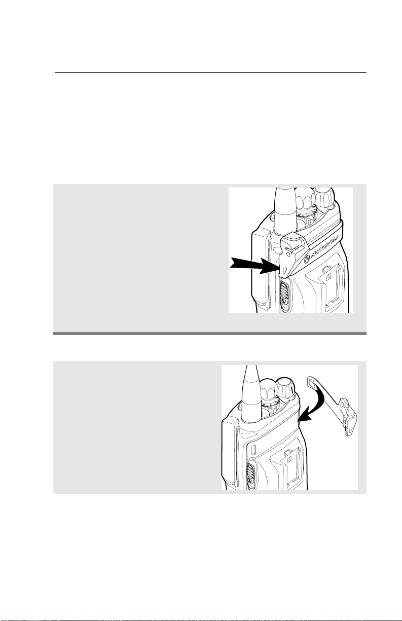
Remove the Adapter
Lift the larger side (below the
antenna port) of the adapter
away from the radio using
your finger.
If you cannot easily remove
the adapter with your finger,
use a small, flat bladed
screwdriver to pry the larger
end side of the adapter away
from the radio.
Attach the Adapter
1 With the Motorola side of the
adapter facing out, snap the
smaller end of the adapter
into place in the shroud
indent, below the On/Off
Volume Control Knob.
ASTRO XTS 2500 / XTS 2500I Model III 23

General Radio Operation
2 Snap the larger end of the
adapter into place in the
shroud indent, below the
antenna port.
24

Radio On and Off
Turn the Radio On
Turn the On/Off/Volume
Control knob clockwise.
• If the power-up test is
successful, you will briefly see
Self Test and then the
home display.
• If the power-up test is
unsuccessful, you will see
ERROR XX/YY. (XX/YY is an
alphanumeric code.) Turn off
the radio, check the battery,
and turn the radio on again. If
the radio continues to fail the
power-up test, record the
ERROR XX/YY code and
contact a qualified service
technician.
General Radio Operation
Self Test
ERROR XX/YY
Turn the Radio Off
Turn the On/Off/Volume
Control knob
counterclockwise until it
clicks.
ASTRO XTS 2500 / XTS 2500I Model III 25

General Radio Operation
Zones and Channels
A zone is a grouping of channels. A channel is a group of radio
characteristics, such as transmit/receive frequency pairs.
Before you use your radio to receive or send messages, you should
select the zone and channel.
Select a Zone
Use the Menu
1 Press U to find ZONE.
ZONE
2 Press D, E, or F
directly below ZONE.
The current zone (in this
case, POL) blinks and the
channel name (DISP NW),
does not blink.
POL DISP NW
3 Press U to find the zone you
want. For example, FIRE.
OR
Use the keypad directly to
dial the zone number.
4 Press h to confirm the
displayed zone and channel.
OR
Press the PTT button to
transmit on the displayed
zone/channel.
26
FIRE DISP NW
FIRE DISP NW

General Radio Operation
Use the Preprogrammed Zone Switch
1 If a control on your radio has
been preprogrammed as the
Zone Switch, move the
Zone Switch to the position
for the zone you want.
Note: If the zone you selected
is unprogrammed, repeat
step 1.
2 Press h to confirm the
displayed zone and channel.
FIRE DISP NW
UNPROGRAMMED
Select a Channel
Consult an authorized service technician for the right choice between
the following methods.
Method 1: Use the Preprogrammed Channel Selector
After the zone you want is
displayed, turn the
preprogrammed Channel
Selector switch to the
desired channel.
ASTRO XTS 2500 / XTS 2500I Model III 27
General Radio Operation
Method 2: Use the Menu
1 Press U to find CHAN.
2 Press D, E, or F
directly below CHAN.
The display shows the
current channel name (in
this case, DISP NW) blinking
and the zone (POL), not
blinking.
3 Press U to find the channel
name you want.
OR
Use the keypad to enter the
channel number.
CHAN
POL DISP NW
POL DISP SE
Note: If the channel you
selected is
unprogrammed, repeat
step 3.
4 Press h to confirm the
displayed zone and channel.
OR
Press the PTT button to
transmit on the displayed
zone/channel.
28
UNPROGRAMMED
POL DISP SE

General Radio Operation
Receive / Transmit
Radio users who switch from analog to digital radios often assume
that the lack of static on a digital channel is an indication that the radio
is not working properly. This is not the case. Digital technology quiets
the transmission by removing the noise from the signal and allowing
only the clear voice or data information to be heard.
This section emphasizes the importance of knowing how to monitor a
channel for traffic before keying-up to send a transmission.
Without Using the Volume Set and Monitor Buttons
1 Turn the radio on and select
the desired zone and
channel.
2 Listen for a transmission.
3 Adjust the Volume Control
knob if necessary.
4 Press and hold the PTT
button to transmit. The LED
lights RED while
transmitting.
5 Release the PTT button to
receive (listen).
ASTRO XTS 2500 / XTS 2500I Model III 29

General Radio Operation
Use Preprogrammed Volume Set Button
1 Turn the radio on and select
the desired zone and
channel. See Turn the
Radio On, page 25 and
Zones and Channels, page
26.
2 Press and hold the Volume
Set button to hear the
volume set tone.
3 Release the Volume Set
button.
4 Adjust the Volume Control
Knob if necessary.
5 Press and hold the PTT
button to transmit. LED lights
RED while transmitting.
6 Release PTT button to
receive (listen).
30

General Radio Operation
Use the Preprogrammed Monitor Button
1 Turn the radio on and select
the desired zone and
channel.
2 Press the Monitor button
and listen for activity. The
Carrier Squelch indicator is
displayed. (See the following
Conventional Mode
Operation.)
3 Adjust the Volume Control
Knob if necessary.
4 Press and hold the PTT
button to transmit.
The LED lights RED while
transmitting.
C
5 Release the PTT button to
receive (listen).
ASTRO XTS 2500 / XTS 2500I Model III 31

General Radio Operation
Conventional Mode Operation
Your radio may be programmed to receive Private Line (PL) calls.
1 Momentarily press the
Monitor button to listen for
activity. The Carrier Squelch
indicator is displayed.
2 Press and hold the Monitor
button to set continuous
monitor operation. (The
duration of the button press
is programmable.)
3 Press the Monitor button
again, or the PTT button, to
return to the original squelch
setting.
Note: If you try to transmit on a
receive-only channel,
you will hear an invalid
tone until you release the
PTT button.
C
32

Common Radio Features
Radio Lock
This feature provides stronger radio security.
If this feature is enabled by a qualified technician, you will see RADIO
LOCKED when you turn the radio on.
Unlock Your Radio
1 Enter your numeric password
of up to 8 characters.
(Use V to backspace if you
make a mistake.)
2 Press the preprogrammed
Select button after you enter
your password. If the
password is correct, the
radio unlocks.
3 Press the preprogrammed
side button to verify the
password. Radio unlocks if
password is correct.
Note: If the password is
incorrect, the radio
remains locked.
________
RADIO LOCKED
Note: DEADLOCK is displayed
after three incorrect
password attempts. Turn
the radio off and on, and
begin again at step 1.
ASTRO XTS 2500 / XTS 2500I Model III 33
DEADLOCK
Common Radio Features
Change Your Password
1 Press U to find PSWD.
2 Press D, E, or F
directly below PSWD.
3 Enter the old password.
4 Press D, E, or F
directly below SEL.
5 Enter new password.
6 Press D, E, or F
directly below SEL.
7 Re-enter password.
8 Press D, E, or F
directly below SEL. The
password is updated.
PSWD
OLD PASSWORD
SEL
NEW PASSWORD
SEL
CONFIRM
SEL
If the two passwords do not
match, repeat steps 5
through 8.
Note: You cannot access this
feature again after three
failed attempts until you
turn the radio off and on.
34
NEW PASSWORD

Mute or Unmute Keypad Tones
You can turn the keypad tones off and on.
Use the Menu
Common Radio Features
1 Press U to find MUTE.
2 Press D, E, or F
directly below MUTE. The
current state is shown.
3 Press D, E, or F
directly below
Note: Press the h or the PTT
button to exit without
changing the setting.
MUTE
TONES OFF
OFF ON
ON
Using the Preprogrammed Side Button
Press the preprogrammed side
button to turn the tones off or on.
TONES ON
or
OFF ON
OFF
or
ASTRO XTS 2500 / XTS 2500I Model III 35

Common Radio Features
Conventional Squelch Options
Analog Squelch
Tone Private Line (PL), Digital Private-Line (DPL), and carrier squelch
can be available (preprogrammed) per channel.
When in... this condition occurs:
Carrier squelch (C) You hear all traffic on a
channel.
PL, DPL The radio responds only
to your messages.
Digital Squelch
One or more of the following options may be programmed in your
radio. Consult your service technician for more information.
This option... allows you to hear:
36
Digital CarrierOperated Squelch
(COS)
Normal Squelch any digital traffic having
Selective Switch any digital traffic having
any digital traffic.
the correct Network
access code.
the correct Network
access code and correct
talkgroup.

Common Radio Features
PL Defeat
With this feature, you can override any coded squelch (DPL, PL, or
network ID) that might be preprogrammed to a channel.
Place the preprogrammed
PL Defeat switch in the PL
Defeat position. You can
now hear any activity on the
channel. The radio is muted
if no activity is present.
When this feature is active,
the Carrier Squelch status
indicator (C) will be
displayed.
C
ASTRO XTS 2500 / XTS 2500I Model III 37

Common Radio Features
Time-out Timer
The time-out timer turns off your radio’s transmitter. The timer is set
for 60 seconds at the factory, but it can be programmed from 0 to 7.75
minutes (465 seconds) by a qualified radio technician.
1 Hold down the PTT longer
than the programmed time.
You will hear a short, lowpitched warning tone, the
transmission is cut-off, and
the LED will go out until you
release the PTT.
2 Release the PTT button. • LED re-lights
3 Press the PTT to re-transmit.
Time-out timer restarts.
• Short warning tone
• Transmission is cut-off
• LED goes out
•Timer resets
• Timer restarts
•RED LED
38

Common Radio Features
Emergency
If the top (orange) button is programmed to send an emergency
signal, then this signal overrides any other communications over the
selected channel.
Your radio can be programmed for the following:
• Emergency Alarm
• Emergency Alarm with Emergency Call, or
• Silent Emergency Alarm
• Emergency Call.
Consult a qualified radio technician for emergency programming of
your radio.
Send an Emergency Alarm
An Emergency Alarm will send a data transmission to the dispatcher,
identifying the radio sending the emergency.
1 With your radio turned on,
press the Emergency
button. The current zone/
channel is displayed
alternately with EMERGENCY,
the LED lights RED, and a
short, medium-pitched tone
sounds.
If the selected channel does
not support emergency, the
display shows NO
EMERGENCY. Select a channel
that does show EMERGENCY.
Note: To exit emergency at any time, press and hold the
Emergency button for about a second.
ASTRO XTS 2500 / XTS 2500I Model III 39
EMERGENCY
•RED LED
• Short Tone
NO EMERGENCY

Common Radio Features
2 When you receive the
dispatcher’s
acknowledgment, you see
ACK RECEIVED, four tones
sound, the alarm ends, and
the radio exits the
emergency mode.
If no acknowledgement is
received, you see NO
ACKNOWLDG, the alarm ends,
and the radio exits the
emergency mode.
Note: For Emergency Alarm with Emergency Call: The radio
enters the Emergency Call state either after it receives the
dispatcher’s acknowledgment, or if you press the PTT button
while in Emergency Alarm. Go to step 2 below: “Send an
Emergency Call.”
ACK RECEIVED
• Four tones
• Alarm ends
• Radio exits emergency
NO ACKNOWLDG
Send an Emergency Call
An Emergency Call will send a type of dispatch giving your radio
priority access to channels.
The radio operates in the normal dispatch manner while in
Emergency Call, except, if enabled, it will return to one of the
following:
Using this operation: means you will talk:
1. Tactical/Non-Revert on the channel you selected
before you entered the
emergency state.
2. Non-Tactical/Revert on a preprogrammed emergency
channel. The emergency alarm is
sent to this same channel.
40

Common Radio Features
1 With your radio turned on,
press the Emergency
button. The current zone/
channel is displayed
alternately with EMERGENCY,
and a short, medium-pitched
tone sounds.
Note: To exit emergency at any time, press and hold the
Emergency button for about a second.
2 Press and hold the PTT
button and announce the
emergency into the
microphone to send the
Emergency call.
3 Release the PTT button to
end the call.
4 Exit the Emergency State by
pressing the Emergency
button again for about one
second (the time may be
changed by a qualified
technician). The radio
returns to normal operation.
EMERGENCY
• Short tone
Send a Silent Emergency Alarm
1 With your radio turned on,
press the Emergency button
if your radio is programmed
for this use.
The display does not
change, the LED does not
light, and no tones sound.
ASTRO XTS 2500 / XTS 2500I Model III 41
• Display does not change
• LED does not light
• No tones

Common Radio Features
Note: To exit emergency at any time, press and hold the
Emergency button for about a second.
2 The silent emergency state
continues until you press and
hold the Emergency button
for about a second to exit the
emergency state.
OR
Press and release the PTT
button to exit silent
emergency. The silent alarm
is cancelled without an exit
tone, and you can begin
transmitting voice calls.
Note: • For ALL Emergency signals: You can change channels
while in Emergency operation if the new channel is also
programmed for Emergency. The emergency alarm or call
continues on the new channel.
• If the new channel is NOT programmed for Emergency, you
see NO EMERGENCY, and hear an invalid tone until you exit
the Emergency state or change to a channel programmed
for emergency.
• Press and hold the
Emergency button
OR
• Press and release the PTT
button
Emergency Keep-Alive
If the radio is in the Emergency state, with Emergency Keep-Alive
enabled, you cannot turn off the radio by using the On/Off Control
knob.
With Keep-Alive, the radio will only exit the Emergency state using
one of the ways mentioned in the previous sections (Emergency
Alarm, Silent Emergency Alarm, or Emergency Call).
42

Common Radio Features
Lists
You can use lists to store frequently used numbers and associate
them with names.
There are four list types:
•Call
•Page
• Phone
• Scan
View a List
1 Press U to find VIEW.
2 Press D, E, or F
directly below VIEW.
3 Press V or U to see the
names of the available lists.
4 Press D, E, or F
directly below the desired list
to view it.
The first list member is
displayed. p indicates the
view mode.
5 Press U or V to view other
list members.
6 Press h to exit.
VIEW
PAGE CALL PHON
FIRE CHIEF p
701234
ASTRO XTS 2500 / XTS 2500I Model III 43

Common Radio Features
Scan List Empty
If the scan list has no
members, EMPTY LIST is
displayed.
EMPTY LIST can be
changed by turning scan off,
or if a qualified technician
adds members to the scan
list.
EMPTY LIST
44

Common Radio Features
Edit a Call, Page, or Phone List Number
Use the Menu
1 Press U to find PROG.
2 Press D, E, or F
directly below PROG.
The changeable lists are
displayed.
3 Press D, E, or F
directly below the list you
wish to change.
First list member is
displayed. Blinking p
indicates programming
mode.
4 Press U or V to select the
list member to be changed.
5 Press D, E, or F
directly below NUM. Blinking
cursor shows location of
number to be added.
OR
PROG
PAGE CALL PHON
FIRE CHIEF p
701234
NUM NAME
SECURITY p
704321
NUM NAME
SECURITY p
70432_
SAVE
You can use the keypad to
enter the corresponding
location number of the name
in the list.
ASTRO XTS 2500 / XTS 2500I Model III 45

Common Radio Features
6 Press V to erase digits. If
you erase the entire number
and press U or V, you exit
the edit mode without saving
your changes. Press a
keypad button to add a digit.
7 Press D, E, or F
directly below SAVE to save
your change.
Return to step 4 to make
more changes.
OR
Press h to return to home
display.
46
Common Radio Features
Edit a Call, Page, or Phone List Name
Use the Menu
1 Press U to find PROG.
2 Press D, E, or F
directly below PROG.
The changeable lists are
displayed.
3 Press D, E, or F
directly below the list you
wish to change.
First list member is
displayed. Blinking p
indicates programming
mode.
4 Press U or V to select the
list member to be changed.
5 Press D, E, or F
directly below NAME. Blinking
cursor shows location of
character to be added.
OR
PROG
PAGE CALL PHON
FIRE CHIEF p
701234
NUM NAME
SECURITY p
704321
NUM NAME
SECURITY_ p
704321
SAVE
You can use the keypad to
enter the corresponding
location number of the name
in the list.
ASTRO XTS 2500 / XTS 2500I Model III 47

Common Radio Features
6 Press V to erase the last
digits. (If you erase the entire
name and press W, you exit
the edit mode without saving
your changes.)
Press a keypad button to add
a character. See “Keypad” on
page 11.
7 Press D, E, or F
directly below SAVE to save
your change.
Return to step 4 to make
more changes.
OR
Press h to return to home
display.
GUARD_ p
704444
SAVE
48

Common Radio Features
Scan
The scan feature allows you to monitor traffic on different channels by
scanning a preprogrammed list of channels. Your radio can have up
to 20 different scan lists. These lists must be preprogrammed by a
qualified technician.
You can view the scan list assigned to the currently selected channel
the same way you would view other lists. See “View a List” on
page 43.
Turn Scan On and Off
Using the Menu
1 Press U to find SCAN.
2 Press D, E, or F
directly below SCAN.
The current scan state is
displayed.
SCAN
SCAN OFF
ON OFF
3 Press D, E, or F
directly below ON or OFF.
When scan is on, the scan
status symbol (T) is
displayed.
OR
To exit the display menu
without changing the scan
state, press h or PTT.
ASTRO XTS 2500 / XTS 2500I Model III 49
ON OFF
SCAN ON
T

Common Radio Features
Use the Preprogrammed Scan On/Off Switch
Place the Scan On/Off switch in
the Scan On or Scan Off
position.
The current scan state is
displayed. When scan is on, the
scan status symbol (T) is
ON OFF
displayed.
Note: To exit the display menu
without changing the
scan state, press h or
PTT.
T
SCAN ON
50

Common Radio Features
Delete a Nuisance Channel
When the radio scans to a channel that you do not wish to hear
(nuisance channel), you can temporarily delete the channel from the
scan list.
1 When the radio is locked
onto the channel to be
deleted, press the
preprogrammed Nuisance
Delete button.
Repeat this step to delete
more channels.
Note: You cannot delete priority
channels or the
designated transmit
channel.
2 The radio continues scanning
the remaining channels in the
list. To resume scanning the
deleted channel, change
channels or turn scan off and
then back on again.
ASTRO XTS 2500 / XTS 2500I Model III 51

Common Radio Features
Conventional Scan Only
Make a Dynamic Priority Change
While the radio is scanning, the dynamic priority change feature lets
you temporarily change any channel in a scan list (except the priorityone channel) to the priority-two channel. The replaced priority-two
channel becomes a non-priority channel. This change remains in
effect until scan is turned off, then scanning reverts back to the
preprogrammed state.
1 When the radio is locked
onto the channel to be
designated as priority-two,
press the preprogrammed
Dynamic Priority button.
Note: The priority-one
channel cannot be
changed to prioritytwo.
2 The radio continues scanning
the remaining channels in the
list. To resume scanning the
preprogrammed priority-two
channel, you must leave and
re-enter scan operation.
52

Common Radio Features
Telephone Calls (Trunking Only)
Use your radio to make and receive standard phone calls. A landline
phone can be used to call a radio, or a radio can be used to call a
landline phone.
Answer a Phone Call
Use the Preprogrammed Call Response Button
1 When a phone call is
received, you hear a
telephone-type ringing, the
LED blinks GREEN, the
call-received symbol (m)
blinks, and PHONE CALL is
displayed.
2 Press the Call Response
button within 20 seconds
after the call indicators
begin.
PHONE CALL
• Telephone ringing
• Blinking GREEN LED
m
3 Press and hold the PTT
button to talk; release it to
listen.
4 Press h to hang up and
return to the home display.
ASTRO XTS 2500 / XTS 2500I Model III 53

Common Radio Features
Make a Phone Call
Use the Menu
1 Press U to find PHON.
2 Press D, E, or F
directly below PHON.
The last phone number is
dialed is displayed.
Note: If you wish to call this
number, go to Step 4.
Otherwise, continue to
Step 3.
PHON
5551234
LIST
3 Press U or V to scroll to the
phone number you want in
the list. Press D, E, or
F directly under LNUM to go
to the last phone number
dialed.
4 Press the PTT button to start
the phone call to the
displayed number.
OR
Press the preprogrammed
Quick Access button to start
the phone call to the
displayed number.
5 Press and hold the PTT
button to talk, release it to
listen.
OR
If your call is not answered,
go to “Phone Call Display
and alert Prompts” on page
page 56.
POLICE
5558523
LNUM
54

6 Press h to hang up and
return to the home display.
Use the Keypad
1 Press U to find PHON.
Common Radio Features
PHON
2 Press D, E, or F
directly below PHON.
You see the last transmitted
or received ID number.
3 Enter the phone number you
want using the keypad.
4 Press the PTT button to start
the phone call to the
displayed number.
OR
Press the preprogrammed
Quick Access button to start
the phone call to the
displayed number.
5 Press and hold the PTT
button to talk, release it to
listen.
OR
If your call is not answered,
go to “Phone Call Display
and alert Prompts” on page
page 56.
5551234
LIST
5558523
LIST
6 Press h to hang up and
return to the home display.
ASTRO XTS 2500 / XTS 2500I Model III 55

Common Radio Features
Phone Call Display and Alert Prompts
• When you press the PTT
button and the phone system
is not available, a long tone
sounds. Press h button, to
hang up. Radio returns to the
home display.
• When a channel is not
available, a busy tone sounds.
The radio will automatically
connect when a channel
opens.
• When the phone system is
busy, a long tone sounds.
Try your call later. Press h
button, to hang up. Radio
returns to the home display.
• The system does not
acknowledge your call. Press
h button, to hang up. Radio
returns to the home display.
Notes: • A high-pitched tone, generated when you release the PTT
button, indicates to the landline party that he or she can
begin talking.
NO PHONE
PHONE BUSY
PHONE BUSY
NO ACKNOWLDG
56
• You have the option of sending additional digits (overdial),
such as an extension number, or credit card or PIN
numbers, to the phone system. If the radio is programmed
for live overdial, every digit entered after the call is
connected is sent to the phone system.
• If the radio is programmed for buffered overdial, the digits
pressed are entered into memory and then sent when the
PTT button is pressed. Press the PTT to send either digits
or voice, but not both at the same time.

Common Radio Features
Private Calls (Trunking Only)
These one-to-one calls between two radios are not heard by others in
the current talkgroup. The calling radio automatically verifies the
receiving radio is active on the system and can display the caller’s ID.
Answer a Private Call
Use the Preprogrammed Call Response Button.
1 When a private call is
received, you hear two alert
tones, the LED blinks
GREEN, the call-received
symbol (m) blinks, and CALL
RECEIVD is displayed.
2 Press the Call Response
button within 20 seconds.
If the caller’s name is in the
call list, it will be displayed.
OR
CALL RECEIVD
•Two tones
• Blinking GREEN LED
m
If the name is not in the call
list, the caller’s ID number
is displayed.
3 Press and hold the PTT
button to talk; release it to
listen.
4 Press h or the Call
Response button to
hang up.
ASTRO XTS 2500 / XTS 2500I Model III 57
Common Radio Features
Make a Private Call
Use the Menu
1 Press U to find CALL.
CALL
2 Press D, E, or F
directly below CALL.
You see the last transmitted
or received ID number
3 Press U or V to scroll to the
ID number you want in the
list.
Note: Press LNUM to go to the
last number dialed.
4 Press the PTT button to start
the Private Call to the
displayed number.
OR
Press the preprogrammed
Quick Access button to start
the private call to the
displayed number.
5 The called ID is momentarily
displayed, followed by
PLEASE WAIT. The called ID
is displayed once connected.
If the system does not
acknowledge the call, NO
ACKNOWLDG is displayed.
If the target radio does not
respond before the time out,
NO ANSWER is displayed.
FIRE CHIEF
ID: 701234
LIST
FIRE CHIEF
ID: 701234
LNUM
PLEASE WAIT
NO ACKNOWLDG
NO ANSWER
58
Use the Keypad
1 Press U to find CALL.
Common Radio Features
CALL
2 Press D, E, or F
directly below CALL.
You see the last transmitted
or received ID number.
3 Use the keypad to enter the
ID number you want to call.
OR
Press the PTT button to start
the Private Call to the
displayed number.
OR
Press the preprogrammed
Quick Access button to start
the phone call to the
displayed number.
4 The called ID is momentarily
displayed, followed by
PLEASE WAIT. The called ID
is displayed once connected.
If the system does not
acknowledge the call, NO
ACKNOWLDG is displayed.
If the target radio does not
respond before the time out,
NO ANSWER is displayed.
FIRE CHIEF
ID: 701234
LIST
FIRE CHIEF
ID: 701234
LIST
PLEASE WAIT
NO ACKNOWLDG
NO ANSWER
ASTRO XTS 2500 / XTS 2500I Model III 59

Common Radio Features
Call Alert Paging
Call Alert allows your radio to work like a pager. Even if other users
are away from their radios, or if they are unable to hear their radios,
you can still send them a Call Alert page. You can also verify if a radio
is active on the system
Answer a Call Alert Page
.
1 When a Call Alert Page is
received, you hear four
repeating alert tones, the
LED blinks GREEN, the
call-received symbol (m)
blinks, and PAGE RECEIVD
is displayed.
2 Press and hold the PTT
button to talk, release it to
listen.
m
PAGE RECEIVD
• Four repeating alert tones
• Blinking GREEN LED
60

Make a Call Alert
Use the Menu
1 Press U to find PAGE.
Common Radio Features
PAGE
2 Press D, E, or F
directly below PAGE.
You see the last transmitted
or received ID number.
3 Use the keypad to enter the
ID number you want to call.
Note: Press LNUM to go to the
last number dialed.
4 Press the PTT button to start
the Call Alert Page to the
displayed number.
OR
Press the preprogrammed
Quick Access button to start
the page to the displayed
number.
PLEASE WAIT is displayed.
The home display appears
once you are connected.
If the system does not
acknowledge the call, NO
ACKNOWLDG is displayed.
FIRE CHIEF
ID: 701234
LIST
FIRE CHIEF
ID: 701234
LNUM
PLEASE WAIT
NO ACKNOWLDG
ASTRO XTS 2500 / XTS 2500I Model III 61

Common Radio Features
Use the Keypad
1 Press U to find PAGE.
PAGE
2 Press D, E, or F
directly below PAGE.
You see the last transmitted
or received ID number.
3 Enter the ID number you
want using the keypad.
4 Press the PTT button to start
the Call Alert Page to the
displayed number.
OR
Press the preprogrammed
Quick Access button to start
the page to the displayed
number.
PLEASE WAIT is displayed.
The home display appears
once you are connected.
If the system does not
acknowledge the call, NO
ACKNOWLDG is displayed.
FIRE CHIEF
ID: 701234
LIST
FIRE CHIEF
ID: 701234
LIST
PLEASE WAIT
NO ACKNOWLDG
62

Common Radio Features
Conventional Talkgroup Calls (Conventional Operation Only)
Talkgroup Call lets you define a group of conventional system users
so that they can share the use of a conventional channel.
Select Talkgroup
1 Press U to find TGRP.
2 Press D, E, or F
directly below TGRP.
The last user-selected-andstored talkgroup, and its
available softkeys, are
displayed.
3 Press U or V to find the
talkgroup you want.
OR
Use the keypad to enter the
number of the desired
corresponding talkgroup in
the list.
4 Press D, E, or F
directly below PSET (to select
the preset or programmed
talkgroup), or below SEL (to
save the talkgroup and return
to the home display).
TGRP
TGRP 1
PSET SEL
5 To exit, press h or the PTT
button, or turn the 16-
Position Select knob.
ASTRO XTS 2500 / XTS 2500I Model III 63

Common Radio Features
Repeater or Direct Operation
Also known as TALKAROUND operation, DIRECT lets you bypass
the repeater and connect directly to another radio. The transmit and
receive frequencies are the same.
REPEATER operation increases the radio’s range by connecting with
other radios through a repeater. Transmit and receive frequencies are
different.
Select Repeater or Direct Operation
Use the Menu
1 Press U to find DIR.
DIR
2 Press D, E, or F
directly below DIR. The
current operation is
momentarily displayed.
3 Press D, E, or F
directly below DIR or RPTR.
If DIR is selected, the display
shows r and DIRECT MODE.
4 Press h to exit display menu
without changing the current
operation.
DIRECT MODE
DIR RPTR
r
DIRECT MODE
RPTR MODE
or
DIR RPTR
64

Special Radio Features
Radio Kill
This feature allows you to render your radio or another radio
inoperable if the radio is misplaced or lost. When a radio is killed, the
display blanks and all functions of the radio will not be usable.
Note: Radio can only be recovered from KILL with a special device.
Contact your Authorized Service Personnel.
There are two ways to initiate the Radio Kill feature:
Remote Kill
Remote Kill allows you to render another radio inoperable by sending
an over the air command using the menu.
1 Press U to find KILL.
2 Press D, E, or F directly
below KILL.
Enter your Tactical Inhibit
Encode Password.
3 Press Button 1 to proceed
4 Enter the targeted Radio ID
manually or select from call list.
5 Press E directly below SEND
to initiate command.
Direct Kill
Direct Kill allows you to make your own radio inoperable.
1 Press and hold Button 1 then press the Orange button until the
display blanks.
ZONE STUN KILL
ENTER PSWD:
ID: 1234
LIST
ASTRO XTS 2500 / XTS 2500I Model III 65

Special Radio Features
Radio Stun
This feature allows you to stun another radio by sending an over the
air command using the menu. When a radio is stunned, it will be
locked to prevent any unauthorized usage of the radio. A password is
required to re-activate the stunned radio.
1 Press U to find STUN.
2 Press D, E, or F directly
below STUN.
Enter your Tactical Inhibit
Encode Password.
3 Press Button 1 to proceed
4 Enter the targeted Radio ID
manually or select from call list.
5 Press E directly below SEND
to initiate command.
Note: To un-stun a radio, follow the Radio Unlock feature on
page 28.
ZONE STUN KILL
ENTER PSWD:
ID: 1234
LIST
66

Special Radio Features
PTT ID
Receive
This feature allows you to see the radio ID number of the radio you
are currently receiving. This ID can be a maximum of eight characters
and can be viewed by both the receiving radio and the dispatcher.
Transmit
Your radio’s ID number is automatically sent every time the PTT
button is pressed. This is a per-channel feature. For digital voice
transmissions, your radio’s ID is sent continuously during the voice
message.
ASTRO XTS 2500 / XTS 2500I Model III 67

Special Radio Features
View Your Radio’s ID Number
Use the Menu
1 Press U or V to find CALL or
PAGE.
2 Press D, E, or F directly
below CALL or PAGE.
CALL
or
PAGE
3 Press V.
Use the Preprogrammed Call or Page Button
1 Press the Call or Page button.
2 Press V.
MY ID:
701111
MY ID:
701111
68

Special Radio Features
Dynamic Regrouping (Trunking Only)
The dynamic regrouping feature lets the dispatcher temporarily
reassign selected radios to a single special channel so they can
communicate with each other. This feature is typically used during
special operations and is enabled by a qualified radio technician. You
will not notice whether your radio has this feature enabled until a
dynamic regrouping command is sent by the dispatcher.
Note: If you try to access a zone or channel that has been reserved
by the dispatcher as a dynamically regrouped mode for other
users, you will hear an invalid tone.
When your radio is dynamically regrouped, it automatically
switches to the dynamically regrouped channel. You see the
dynamically regrouped channel’s name, and hear a “gurgle”
tone.
Press the PTT button to talk; release it to listen.
When the dispatcher cancels dynamic regrouping, the radio
automatically returns to the zone and channel that you were
using before the radio was dynamically regrouped.
Reprogram Request (ASTRO 25 Trunking Only)
This feature lets you notify the dispatcher that you want a new
dynamic regrouping assignment.
Use the Menu
1 Press U to find RPGM.
2 Press D, E, or F directly
below RPGM.
The reprogram request is sent
to the dispatcher.
ASTRO XTS 2500 / XTS 2500I Model III 69
RPGM
REPRGRM RQST

Special Radio Features
3 If you hear one beep
- Press the PTT button to send
the reprogram request again.
OR
- Press h to cancel and return
to the home display.
OR
If you hear five beeps, the
reprogram request was
acknowledged by the dispatcher. Your radio returns to
the home display.
OR
If the dispatcher does not
NO ACKNOWLDG
acknowledge the reprogram
request within six seconds, you
see NO ACKNOWLDG and hear a
• An alert tone
low-pitched alert tone.
Try again or press h.
Use the Preprogrammed Reprogram Request Button
1 Press the Reprogram
REPRGRM RQST
Request button. You see
REPRGRM RQST.
The reprogram request is sent
to the dispatcher.
70

Special Radio Features
2 If you hear one beep
- Press the PTT button to send
the reprogram request again
OR
-Press h to hang up and
return to the home display.
OR
If you hear five beeps, the
reprogram request was
acknowledged by the dispatcher. Your radio returns to
the home display.
OR
If the dispatcher does not
acknowledge the reprogram
request within six seconds, you
see NO ACKNOWLDG and hear a
low-pitched alert tone.
Try again or press h.
• One beep
• Five beeps
NO ACKNOWLDG
• An alert tone
Select Enable / Disable
The dispatcher can classify regrouped radios into either of two
categories: Select Enabled or Select Disabled.
• Select-enabled radios are free to change to any available channel,
including the dynamic-regrouping channel, once the user has
selected the dynamic-regrouping position.
• Select-disabled radios cannot change channels while dynamically
regrouped. The dispatcher has forced the radio to remain on the
dynamic-regrouping channel.
The Scan or Private Call feature cannot be selected while your radio
is Select Disabled.
ASTRO XTS 2500 / XTS 2500I Model III 71

Special Radio Features
Trunking System Controls
Failsoft
The failsoft system ensures continuous radio communications during
a trunked system failure. If a trunking system fails completely, the
radio goes into failsoft operation and automatically switches to its
failsoft channel.
During failsoft operation:
Your radio transmits and
receives in conventional
operation on a
predetermined frequency.
FAILSOFT
You hear a medium-pitched
tone every 10 seconds.
When the trunking system returns to normal operation, your radio
automatically leaves failsoft operation and returns to trunked
operation.
• Medium-pitched tone
Out-of-Range
If you go out of the range of the system, and can no longer lock onto a
control channel:
The display shows OUT OF
RANGE and the currently selected
zone/channel combination, and/
or you hear a low-pitched tone.
Your radio remains in this out-ofrange condition until it locks onto
a control channel, or it locks
onto a failsoft channel, or it is
turned off.
OUT OF RANGE
AND/OR
• Low-pitched tone
• Locks onto a control channel,
or
• Locks onto a failsoft channel,
or
• Turned off.
72
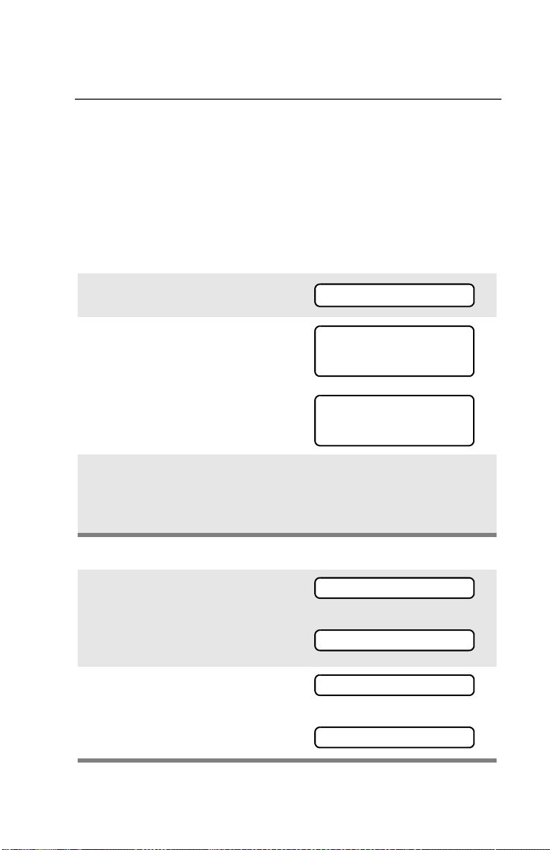
Special Radio Features
Site Lock
This feature allows your radio to lock onto a specific site and not roam
among wide-area talkgroup sites. This feature should be used with
caution, since it inhibits roaming to another site in a wide-area
system.
Lock or Unlock a Site
Use the Menu
1 Press U or V to find SITE.
SITE
2 Press D, E, or F directly
below SITE.
The current lock state is
displayed.
3 Press D, E, or F directly
below LOCK or UNLK.
Use the Preprogrammed Site Lock/Unlock Button
1 Press the Site Lock/Unlock
button.
The current lock state is
momentarily displayed.
2 Press and hold the Site Lock/
Unlock button until you see the
desired lock state.
SITE UNLOCKED
LOCK UNLK
SITE LOCKED
LOCK UNLK
• The new site-lock state is
saved.
• Your radio returns to the
home display.
SITE LOCKED
OR
SITE UNLOCKED
SITE LOCKED
OR
SITE UNLOCKED
ASTRO XTS 2500 / XTS 2500I Model III 73

Special Radio Features
Site Trunking
If the zone controller loses communication with any site, that site
reverts to what is known as “site trunking.” The display shows “SITE
TRUNKNG” and the currently selected zone/channel combination.
When this occurs, you can communicate only with other radios within
your trunking site.
Site View and Change
You can view the ID number of the current site or force your radio to
change to a new one.
View the Current Site
Momentarily press the
preprogrammed Site Search
button.
The display shows the name
of the current site and its
corresponding Received
Signal Strength Indicator
(RSSI) symbol (s)
OR
If the radio is scanning for a
new site, the display
momentarily shows SCANING
SITE.
s
SITE 2
SCANING SITE
74

Change the Current Site
Press and hold down the
preprogrammed Site Search
button to manually force the
change to a new site.
Special Radio Features
You hear a tone, and the
display shows SCANING
SITE while the radio scans
for a new site.
The radio returns to the
home display when it finds a
new site.
•Tone
SCANING SITE
ASTRO XTS 2500 / XTS 2500I Model III 75

Special Radio Features
Time and Date
Using this special feature, you may program the time and date as you
might with other electronic devices. The clock display is enabled by a
qualified radio technician.
• The default time setting is a 12hour clock.
• If a 24-hour clock is selected, AM/
PM selection is not available.
• The default setting for the
domestic date shows MDY.
Edit Time and Date
1 Press U to find CLCK.
2 Press D, E, or F directly
below CLCK. The current setting
is displayed.
3 Press D, E, or F directly
below EDIT.The first item blinks.
4 Press X or Y to change the
selected item.
12HR 00:00AM
MDY 00/00/00
CLCK
12HR 03:54AM
MDY 03/07/01
EDIT
12HR 03:54AM
MDY 03/07/01
SAVE
24HR 03:54
MDY 03/07/01
76
SAVE
Note: Press h at any time to return
to the home display without
saving your changes.
OR
Press U one or more times to
move to an item you wish to
change.
Special Radio Features
12HR 03:54AM
MDY 03/07/01
SAVE
5 Press X or Y to change the
selected item.
12HR 03:58AM
MDY 03/07/01
SAVE
6 Press U one or more times to
move to an item in the date field.
12HR 03:58AM
MDY 03/07/01
SAVE
7 Press X or Y to change the
selected item.
12HR 03:58AM
MDY 03/08/01
SAVE
8 When you have made all your
changes, press D, E, or F
directly below SAVE to save your
changes and return to the Home
display.
Note: If a call arrives while the radio is in the clock-setting menu,
the radio exits clock setting, your changes are lost, and the
call information is displayed.
ASTRO XTS 2500 / XTS 2500I Model III 77

Special Radio Features
Outdoor Location (using GPS)
The Outdoor Location (using GPS) feature allows radio users to
determine their current location using a location menu. Radio location
may be requested and reported over-the-air.
This feature is only available when a location enabled accessory such
as the GPS Remote Speaker Microphone (RSM) is attached to the
radio.
Access the Location feature
Use the Menu
1 Press U to find LOC.
2 Press D, E, or F
directly below LOC.
If radio has just been
switched on, or no location
signal is available (blinking
icon), the display shows the
latitude and longitude of the
last successful location fix.
The top line will display
PREVIOUS LOC.
LOC
PREVIOUS LOC
47N 13.227’
118W 16.194’
R F SH O F F
As soon as a location signal
is detected (solid icon), the
display will be updated with
the new location coordinates.
The location coordinates will
be updated automatically
every four minutes while the
location signal is present.
78
50N 10.245’
120W 15.238’
R F SH O F F

Special Radio Features
3 Press D, E, or F
directly below RFSH to obtain
a new location fix. The top
line will temporarily display
PLEASE WAIT while the new
location is being determined.
Note: While the new location
is being determined, the
location signal can be solid
or blinking icon.
4 Press D, E, or F
directly below OFF to disable
the location feature to save
battery power.
OR
Press D, E, or F
directly below ON to enable
the location feature.
Note: An ON/OFF menu key
may be present on the
location menu if it is
programmed by the service
technician.
PLEASE WAIT
50N 10.245’
120W 15.238’
R F SH O F F
50N 10.245’
120W 15.238’
R F SH O F F
LOCATION OFF
50N 10.245’
120W 15.238’
RFSH O N
Press h or the PTT button to
exit this menu.
If the emergency button is
pressed or the GPS RSM is
disconnected, radio will also
exits this menu.
ASTRO XTS 2500 / XTS 2500I Model III 79

Special Radio Features
Location and Emergency Feature Interaction
When the Emergency feature is activated by pressing the emergency
button, the radio will exit the Location menu and return to the home
(default) display so that you can see which channel the emergency
signal is going out on. However, you may re-enter the Location menu
while still in emergency mode, provided that Silent Emergency has
not been activated.
If you have turned Location off using the ON/OFF menu key, it will be
automatically turned back on when Emergency is activated.
GPS Enabled
Your RSM’s GPS Enabled feature uses information from the Global
Positioning System (GPS) satellites orbiting the Earth to determine
the approximate geographical location of your RSM, expressed as
latitude and longitude. The availability and accuracy of this location
information (and the amount of time that it takes to calculate it) will
vary depending on the environment in which you are using the GPS
feature.
For example, GPS location fixes are very difficult to obtain indoors, in
covered locations, between high buildings, or in situations where you
have not established a clear broad view of the sky.
IMPORTANT: Things to Keep in Mind
The GPS technology uses radio signals from earth orbiting satellites,
to establish the location co-ordinates, maximizing your view of clear
unobstructed sky is essential for optimum performance. Where
adequate signals from multiple satellites are not available (usually
because you cannot establish a view of a wide area of the sky), the
GPS feature of your RSM will not work. Such situations include but
are not limited to:
• In underground locations
• Inside of buildings, trains, or other covered vehicles
• Under any other metal or concrete roof or structure
• Between tall buildings or under dense tree-cover
80

Special Radio Features
• In temperature extremes outside the operating limits of your RSM
Even where location information can be calculated in such situations,
it may take longer to do so, and your location estimate may not be as
accurate. Therefore, in any emergency situation, always report your
location to your dispatcher.
Furthermore, please note that even where adequate signals from
multiple satellites are available, your GPS feature will only provide an
approximate location, often within 20-100 meters from your actual
location, but sometimes much further from the actual location.
Keep in mind that the accuracy of the location information and the
time it takes to obtain it varies depending upon circumstances,
particularly the ability to receive signals from an adequate number of
satellites.
The satellites used by the GPS feature are controlled by the U.S.
government and are subject to changes implemented in accordance
with the Department of Defense GPS user policy and the Federal
Radio Navigation Plan. These changes may affect the performance of
the GPS feature on your RSM.
Enhancing GPS Performance
Sometimes, the GPS feature of your RSM may be unable to complete
a location calculation successfully. You will then see a message
indicating that your RSM cannot see enough visible satellites.
To maximize the ability of your RSM to determine a fix, please note
the following guidelines:
• Stay in the open. The GPS feature works best where there is
nothing between your RSM and a large amount of open sky.
• Wear your RSM outside all clothing. Keep it as high on your body
as possible, ideally at shoulder level.
ASTRO XTS 2500 / XTS 2500I Model III 81

Special Radio Features
Notes
82

ARS User Login and Text Messaging
Features
Automatic Registration Service (ARS)
The Automatic Registration Service feature provides an automated
data application registration for the radio. When you turn on the radio,
the device automatically registers with the server. Data applications
within the fixed network can determine the presence of a device on
the system and send data to the device. For example: Text
Messaging Service (TMS).
The Automatic Registration Service for the radio consists of 2 modes:
• ARS Server Mode (default mode)
• ARS Non Server Mode
Note: The default ARS mode can be changed by a qualified
radio technician using the radio’s programming software.
Selecting or Changing ARS Mode
Consult a qualified radio technician for the right choice between the
following methods:
Method 1: Use the Preprogrammed 16-Position Select Knob
After the zone you want is
displayed, turn the
16-Position Select knob to
the desired mode.
Method 2: Use the Menu
1 Press U to find CHAN.
Select
Mode
CHAN
ASTRO XTS 2500 / XTS 2500I Model III 83
 Loading...