

Page 1
M
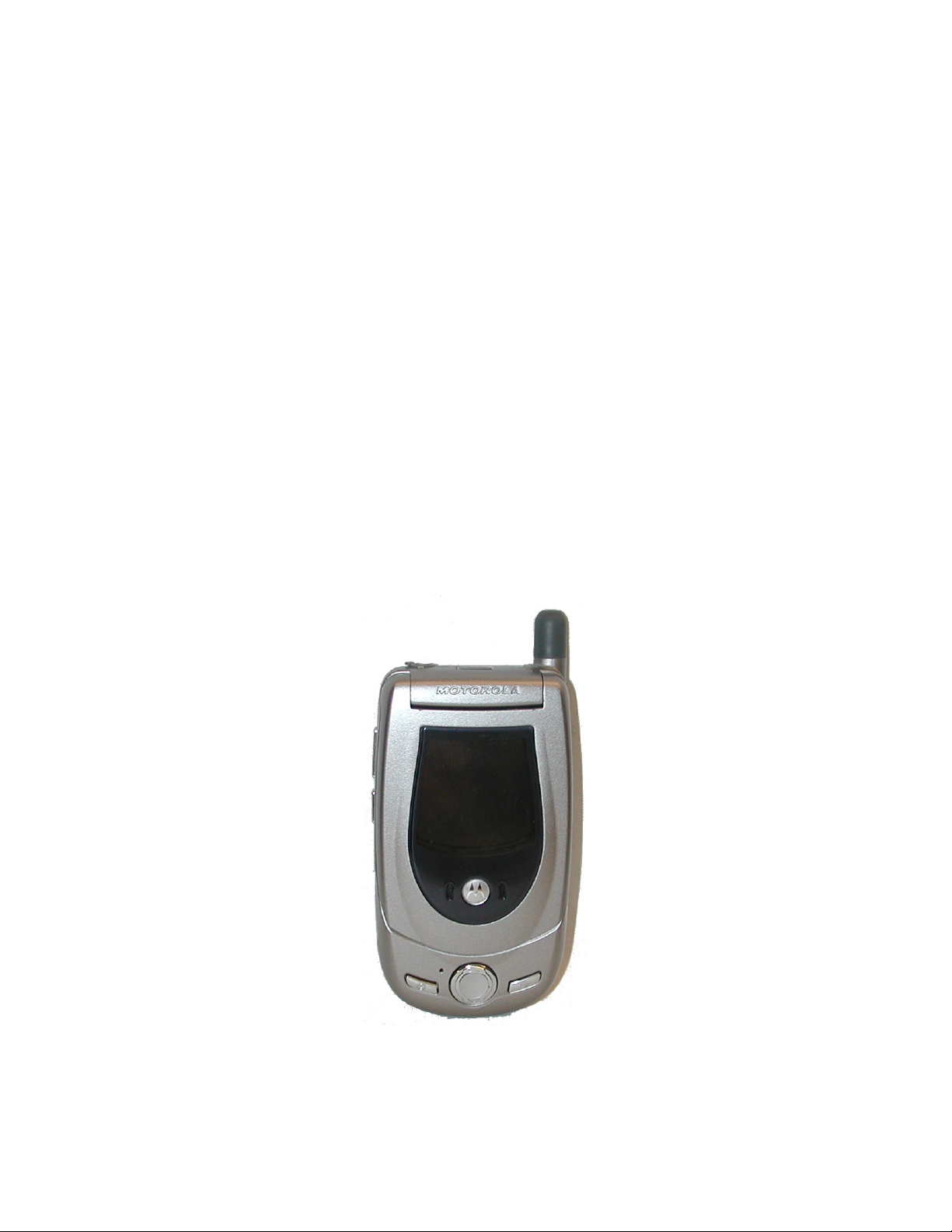
Dual Band Wireless Telephone
Level 1 and 2 Service Manual
A760
GSM 900/1800 MHz & GPRS Technologies
Page 2

Page 3

1 and 2
Table of Contents
Level 1 and 2 Service Manual Table of Contents
A760
6809464A70
Introduction . . . . . . . . . . . . . . . . . . . . . . . . . . . . . . . . . . . . . . . . . . . . . . . . . . . . . . . . . . . . . . . . . . . . . . . . . . . . . . . . . 5
Product Identification . . . . . . . . . . . . . . . . . . . . . . . . . . . . . . . . . . . . . . . . . . . . . . . . . . . . . . . . . . . . . . . . . . . 5
Product Names . . . . . . . . . . . . . . . . . . . . . . . . . . . . . . . . . . . . . . . . . . . . . . . . . . . . . . . . . . . . . . . . . . . . . . . . 5
Product Changes . . . . . . . . . . . . . . . . . . . . . . . . . . . . . . . . . . . . . . . . . . . . . . . . . . . . . . . . . . . . . . . . . . . . . . . 5
Regulatory Agency Compliance . . . . . . . . . . . . . . . . . . . . . . . . . . . . . . . . . . . . . . . . . . . . . . . . . . . . . . . . . . . 5
Computer Program Copyrights . . . . . . . . . . . . . . . . . . . . . . . . . . . . . . . . . . . . . . . . . . . . . . . . . . . . . . . . . . . 6
About this Service Manual . . . . . . . . . . . . . . . . . . . . . . . . . . . . . . . . . . . . . . . . . . . . . . . . . . . . . . . . . . . . . . . 6
Warranty Service Policy . . . . . . . . . . . . . . . . . . . . . . . . . . . . . . . . . . . . . . . . . . . . . . . . . . . . . . . . . . . . . . . . . 7
Parts Replacement . . . . . . . . . . . . . . . . . . . . . . . . . . . . . . . . . . . . . . . . . . . . . . . . . . . . . . . . . . . . . . . . . . . . . 8
Specifications . . . . . . . . . . . . . . . . . . . . . . . . . . . . . . . . . . . . . . . . . . . . . . . . . . . . . . . . . . . . . . . . . . . . . . . . . . . . . . 9
Product Overview . . . . . . . . . . . . . . . . . . . . . . . . . . . . . . . . . . . . . . . . . . . . . . . . . . . . . . . . . . . . . . . . . . . . . . . . . . . 10
Features . . . . . . . . . . . . . . . . . . . . . . . . . . . . . . . . . . . . . . . . . . . . . . . . . . . . . . . . . . . . . . . . . . . . . . . . . . . . . 11
General Operation . . . . . . . . . . . . . . . . . . . . . . . . . . . . . . . . . . . . . . . . . . . . . . . . . . . . . . . . . . . . . . . . . . . . . . . . . . . 12
Controls, Indicators, and Input/Output (I/O) Connections . . . . . . . . . . . . . . . . . . . . . . . . . . . . . . . . . . . . . 12
Alert Settings . . . . . . . . . . . . . . . . . . . . . . . . . . . . . . . . . . . . . . . . . . . . . . . . . . . . . . . . . . . . . . . . . . . . . . . . 16
Battery Function . . . . . . . . . . . . . . . . . . . . . . . . . . . . . . . . . . . . . . . . . . . . . . . . . . . . . . . . . . . . . . . . . . . . . . 16
Operation . . . . . . . . . . . . . . . . . . . . . . . . . . . . . . . . . . . . . . . . . . . . . . . . . . . . . . . . . . . . . . . . . . . . . . . . . . . . 16
Tools and Test Equipment . . . . . . . . . . . . . . . . . . . . . . . . . . . . . . . . . . . . . . . . . . . . . . . . . . . . . . . . . . . . . . . . . . . . 17
Disassembly . . . . . . . . . . . . . . . . . . . . . . . . . . . . . . . . . . . . . . . . . . . . . . . . . . . . . . . . . . . . . . . . . . . . . . . . . . . . . . . . 18
Removing and Replacing the Battery Door . . . . . . . . . . . . . . . . . . . . . . . . . . . . . . . . . . . . . . . . . . . . . . . . . 18
Removing and Replacing the Battery Door . . . . . . . . . . . . . . . . . . . . . . . . . . . . . . . . . . . . . . . . . . . . . . . . . 18
Removing and Replacing the Battery . . . . . . . . . . . . . . . . . . . . . . . . . . . . . . . . . . . . . . . . . . . . . . . . . . . . . 19
Removing and Replacing the Subscriber Identity Module (SIM) . . . . . . . . . . . . . . . . . . . . . . . . . . . . . . . . 20
Removing and Replacing the Stylus . . . . . . . . . . . . . . . . . . . . . . . . . . . . . . . . . . . . . . . . . . . . . . . . . . . . . . 21
Removing and Replacing the Antenna . . . . . . . . . . . . . . . . . . . . . . . . . . . . . . . . . . . . . . . . . . . . . . . . . . . . 22
Removing and Replacing the Rear Housing . . . . . . . . . . . . . . . . . . . . . . . . . . . . . . . . . . . . . . . . . . . . . . . . 23
Removing and Replacing the Transceiver Board . . . . . . . . . . . . . . . . . . . . . . . . . . . . . . . . . . . . . . . . . . . . 25
Removing and Replacing the Camera Assembly . . . . . . . . . . . . . . . . . . . . . . . . . . . . . . . . . . . . . . . . . . . . . 26
Removing and Replacing the Real Time Clock (RTC) Battery . . . . . . . . . . . . . . . . . . . . . . . . . . . . . . . . . . 27
Removing and Replacing the Keypad . . . . . . . . . . . . . . . . . . . . . . . . . . . . . . . . . . . . . . . . . . . . . . . . . . . . . 28
Removing and Replacing the Touch Screen Display Assembly . . . . . . . . . . . . . . . . . . . . . . . . . . . . . . . . . 29
Removing and Replacing the Microphone . . . . . . . . . . . . . . . . . . . . . . . . . . . . . . . . . . . . . . . . . . . . . . . . . . 32
SIM Cards and Identification . . . . . . . . . . . . . . . . . . . . . . . . . . . . . . . . . . . . . . . . . . . . . . . . . . . . . . . . . . . . . . . . . . 33
SIM Card . . . . . . . . . . . . . . . . . . . . . . . . . . . . . . . . . . . . . . . . . . . . . . . . . . . . . . . . . . . . . . . . . . . . . . . . . . . . 33
Personality Transfer . . . . . . . . . . . . . . . . . . . . . . . . . . . . . . . . . . . . . . . . . . . . . . . . . . . . . . . . . . . . . . . . . . . 33
Identification . . . . . . . . . . . . . . . . . . . . . . . . . . . . . . . . . . . . . . . . . . . . . . . . . . . . . . . . . . . . . . . . . . . . . . . . . 33
Troubleshooting . . . . . . . . . . . . . . . . . . . . . . . . . . . . . . . . . . . . . . . . . . . . . . . . . . . . . . . . . . . . . . . . . . . . . . . . . . . . 35
Manual Test Mode . . . . . . . . . . . . . . . . . . . . . . . . . . . . . . . . . . . . . . . . . . . . . . . . . . . . . . . . . . . . . . . . . . . . 35
Manual Test Mode Commands . . . . . . . . . . . . . . . . . . . . . . . . . . . . . . . . . . . . . . . . . . . . . . . . . . . . . . . . . . . 35
Troubleshooting Chart . . . . . . . . . . . . . . . . . . . . . . . . . . . . . . . . . . . . . . . . . . . . . . . . . . . . . . . . . . . . . . . . . 36
Programming: Software Upgrade and Flexing . . . . . . . . . . . . . . . . . . . . . . . . . . . . . . . . . . . . . . . . . . . . . . 39
Part Number Charts . . . . . . . . . . . . . . . . . . . . . . . . . . . . . . . . . . . . . . . . . . . . . . . . . . . . . . . . . . . . . . . . . . . 39
Related Publications . . . . . . . . . . . . . . . . . . . . . . . . . . . . . . . . . . . . . . . . . . . . . . . . . . . . . . . . . . . . . . . . . . . 39
Exploded View Diagram . . . . . . . . . . . . . . . . . . . . . . . . . . . . . . . . . . . . . . . . . . . . . . . . . . . . . . . . . . . . . . . . 40
Exploded View Parts List . . . . . . . . . . . . . . . . . . . . . . . . . . . . . . . . . . . . . . . . . . . . . . . . . . . . . . . . . . . . . . . 41
Accessories . . . . . . . . . . . . . . . . . . . . . . . . . . . . . . . . . . . . . . . . . . . . . . . . . . . . . . . . . . . . . . . . . . . . . . . . . . . 41
Index . . . . . . . . . . . . . . . . . . . . . . . . . . . . . . . . . . . . . . . . . . . . . . . . . . . . . . . . . . . . . . . . . . . . . . . . . . . . . . . . . . Index-1
6809464A70 August 26, 2003 3
Page 4

Table of Contents Product Family A760
4 August 26, 2003 6809464A70
Page 5

1 and 2
A760
Level 1 and 2 Service Manual Introduction
6809464A70
Introduction
Motorola® Inc. maintains a worldwide organization that is dedicated to provide
responsive, full-service customer support. Motorola products are serviced by an
international network of company-operated product care centers as well as
authorized independent service firms.
Available on a contract basis, Motorola Inc. offers comprehensive maintenance and
installation programs that enable customers to meet requirements for reliable,
continuous communications.
To learn more about the wide range of Motorola service programs, contact your local
Motorola products representative or the nearest Customer Service Manager.
Product Identification
Motorola products are identified by the model number on the housing. Use the entire
model number when inquiring about the product. Numbers are also assigned to
chassis and kits. Use these numbers when requesting information or ordering
replacement parts.
Product Names
Product names are listed on the front cover. Product names are subject to change
without notice. Some product names, as well as some frequency bands, are available
only in certain markets.
Product Changes
When electrical, mechanical or production changes are incorporated into Motorola
products, a revision letter is assigned to the chassis or kit affected, for example:
-A, -B, or -C.
The chassis or kit number, complete with revision number is imprinted during
production. The revision letter is an integral part of the chassis or kit number and
is also listed on schematic diagrams and printed circuit board layouts.
Regulatory Agency Compliance
This device complies with Part 15 of the FCC Rules. Operation is subject to the
following conditions:
• This device may not cause any harmful interference, and
• must accept interference received, including interference that may cause
undesired operation.
This class B device also complies with all requirements of the Canadian
Interference-Causing Equipment Regulations (ICES-003).
Cet appareil numérique de la classe B respecte toutes les exigences du Règlement
sur le matériel brouilleur du Canada.
6809464A70 August 26, 2003 5
Page 6

6809464A70
A760
Introduction A760
1 and 2
Computer Program Copyrights
The Motorola products described in this manual may include Motorola computer
programs stored in semiconductor memories or other media that are copyrighted
with all rights reserved worldwide to Motorola. Laws in the United States and other
countries preserve for Motorola, Inc. certain exclusive rights to the copyrighted
computer programs, including the exclusive right to copy, reproduce, modify,
decompile, disassemble, and reverse-engineer the Motorola computer programs in
any manner or form without Motorola's prior written consent. Furthermore, the
purchase of Motorola products shall not be deemed to grant either directly or by
implication, estoppel, or otherwise, any license or rights under the copyrights,
patents, or patent applications of Motorola, except for a nonexclusive license to use
the Motorola product and the Motorola computer programs with the Motorola
product.
About this Service Manual
Using this service manual and the suggestions contained in it assures proper
installation, operation, and maintenance of A760 telephones. Refer questions about
this manual to the nearest Customer Service Manager.
Audience
This manual aids service personnel in testing and repairing A760 telephones.
Service personnel should be familiar with electronic assembly, testing, and
troubleshooting methods, and with the operation and use of associated test
equipment.
Use of this manual assures proper installation, operation, and maintenance of
Motorola products and equipment. It contains all service information required for
the equipment described and is current as of the printing date.
Scope
The scope of this document is to provide the basic information relating to A760
telephones, and also to provide procedures and processes for repairing the units at
Level 1 and 2 service centers including:
•Unit swap out
• Repairing of mechanical faults
• Basic modular troubleshooting
• Testing and verification of unit functionality
• Initiate warranty claims and send faulty modules to Level 3 or 4 repair centers
6 August 26, 2003 6809464A70
Page 7

Level 1 and 2 Service Manual Introduction
Conventions
Special characters and typefaces, listed and described below, are used in this
manual to emphasize certain types of information.
➧
G
E
M
Note: Emphasizes additional information pertinent to the subject
matter.
Caution: Emphasizes information about actions that may result in
equipment damage.
Warning: Emphasizes information about actions that may result in
personal injury.
Keys to be pressed are represented graphically. For example, instead of “Press
the Menu key”, you will see “Press
Information from a screen is shown in text as similar as possible to what
appears in the display. For example, ALERTS or ALERTS or ALERTS.
Information that you need to type is printed in boldface type
M”.
Revisions
Any changes that occur after manuals are printed are described in publication
revision bulletins (PMRs). These bulletins provide change information that can
include new parts listing data, schematic diagrams, and printed circuit board
layouts.
Warranty Service Policy
The product comes with the standard 12-month warranty terms and conditions.
Accidental damage, misuse, and extended warranties offered by retailers are not
supported under warranty. Non warranty repairs are available at agreed fixed
repair prices.
Out of Box Failure Policy
The standard out of box failure criteria applies. Customer units that fail very early
on after the date of sale, are to be returned to Manufacturing for root cause analysis,
to guard against epidemic criteria. Manufacturing will bear the costs of early life
failure.
Product Support
Customer’s original units will be repaired but not refurbished as standard.
Appointed Motorola Service Hubs will perform warranty and non-warranty field
service for level 2 (assemblies) and level 3 (limited PCB component). The Motorola
High Technology Centers will perform level 4 (full component) repairs.
6809464A70 August 26, 2003 7
Page 8

Introduction A760
Customer Support
Customer support is available through dedicated Call Centers and in-country help
desks. Product Service training should be arranged through the local Motorola
Support Center.
Ordering Replacement Parts
Only centers authorized to carry out repairs can purchase spare parts. Orders for
spare parts from hubs and Hi-Tech Centers should be placed with the regional
Motorola Parts Distribution Center.
Parts Replacement
When ordering replacement parts or equipment, include the Motorola part number
and description used in the service manual or supplement.
When ordering crystals or channel elements, specify the Motorola part number,
description, crystal frequency, and operating frequency desired.
When the Motorola part number of a component is not known, use the product model
number or other related major assembly along with a description of the related
major assembly and of the component in question.
In the U.S.A., to contact Motorola, Inc. on your TTY, call: 800-793-7834
Accessories and Aftermarket Division (AAD)
Replacement parts, test equipment, and manuals can be ordered from AAD.
U.S.A. Outside U.S.A.
Phone: 800-422-4210 Phone: 847-538-8023
FAX: 800-622-6210 FAX: 847-576-3023
To order spare parts in EMEA region call +44 131 479 1274.
To order spare parts in Asia region call +65 648 62995.
8 August 26, 2003 6809464A70
Page 9
Level 1 and 2 Service Manual Specifications
Specifications
General Function Specification
Frequency Range GSM
Frequency Range DCS
Channel Spacing 200 kHz
Channels 174 EGSM, 374 DCS carriers with 8 ch. per carrier
Modulation GMSK at BT = 0.3
Transmitter Phase Accuracy 5 Degrees RMS, 20 Degrees peak
Duplex Spacing 45 MHz GSM, 95 MHz DCS
Frequency Stability ± 0.10 ppm of the downlink frequency (Rx)
Operating Voltage
Transmit Current Typically 350 mA average, 1.0 Amps peak
Stand-by Current Typically 5.0 mA (DRX2), 8.3 mA (DXR9)
Dimensions
Size (Volume) 95 cc (5.79 in
Weight 118 gm (4.1 oz) with battery
Temperature Range -10° C to +55° C (+15° F to +130° F)
Battery Life, 800 mAh
Lithium Ion Battery
880-915 MHz Tx (with EGSM)
925-960 MHZ Rx
1710-1785 MHz Tx
1805-1880 MHz Rx
+3.0V dc to +5.1V dc (battery)
+4.4V dc to +6.5V dc (external connector)
101 mm x 53 mm x 21 mm (3.9 inches X 2.1 inches X 0.8
inches)
Talk Time 180 to 300 minutes
Standby 95 to 160 hours
All talk and standby times are approximate and depend on
network configuration, signal strength, and features selected.
Standby times are quoted as a range from DRX=2 to DRX=9.
Talk times are quoted as a range from DTX off to DTX on.
3
)with battery
Transmitter Function Specification
RF Power Output 33 dBm nominal GSM, 30 dBm nominal DCS
Output Impedance 50 ohms nominal
Spurious Emissions -36 dBm from 0.1 to 1 GHz, -30 dBm from 1 to 4 GHz
Receiver Function Specification
Receive Sensitivity -102 dBm GSM, -103 dBm DCS
RX bit error rate (100k bits) Type II < 2%
Channel Hop Time 500 microseconds
Time to Camp Approximately 5-10 seconds
Speech Coding Function Specification
Speech Coding Type
Bit Rate 13.0 kbps
Frame Duration 20 ms
Block Length 260 bits
Classes Class 1 bits = 182 bits; Class 2 bits = 78 bits
Bit Rate with FEC Encoding 22.8 kbps
Regular pulse excitation / linear predictive coding with long
term prediction (RPE LPC with LTP)
6809464A70 August 26, 2003 9
Page 10

Product Overview A760
Product Overview
Motorola A760 telephones are global system for mobile communications (GSM)
general packet radio service (GPRS) wireless application protocol (WAP)-enabled
mobile phones with full-featured personal information manager (PIM)
functionality. The A760 incorporates a large task-based touch screen user interface
(UI) featuring handwriting recognition for email and short message service (SMS)
text messaging. It is a tri-band phone that allows roaming within the GSM 900
MHz, and digital cellular system (DCS) 1800 MHz bands.
A760 telephones support GPRS, SMS, MMS in addition to traditional circuit
switched transport technologies.
A760 telephones have a clam form factor. They are made of a polycarbonate plastic
with the earpiece speaker located in the flip. The flip features a viewing window
that allows a portion of the display to be seen with the flip is closed. The bottom
part of the clam (front housing) contains the touch screen display, main printed
circuit board (PCB), microphone, external accessory connector, infrared (IR)
communications port, and headset jack. Also located in the front housing are the
voice, volume, power, page up, page down, and menu buttons, as well as the battery,
antenna, subscriber identity module (SIM) holder, and status light. A stylus, also
located in the front housing, is provided to aid manipulating the touch screen UI.
The A760 features a High definition display with a fine pitch 320 x 240 pixel high
color reflective TFT display to improve readability and useability.
The battery and battery door are integrated into a single unit to minimize overall
phone thickness. The phone accepts both 3V and 5V mini SIM cards which fit into
the SIM holder beneath the battery. The antenna is a fixed stub type antenna.
10 August 26, 2003 6809464A70
Page 11

Level 1 and 2 Service Manual Product Overview
Features
Features available include:
• Phone first: looks and performs like a phone
• Linux OS
• J2ME™ MIDP 2.0
• Hands free speakerphone
• 65k color TFT touchscreen
• Touchscreen pen-based input with handwriting recognition
• Secure OTA synchronization of PIM & email to enterprise servers
• Supports MMS, high definition audio codecs (MIDI, AMR, MP3) in addition to
traditional SMS, concatenated SMS, cell broadcast messages, and 2D/3D
animation
• Polyphonic ringer tones (16 voice, 22kHz)
• Embedded MP3 player
• Embedded camera
• Embedded Bluetooth™
• MPEG4 playback
• 200 MHz processor
• 32 MB flash memory
• Embedded PIM and email clients with excellent UI and performance
• Tri-coder/decoder (CODEC) that allows full rate, half rate, and enhanced full
rate modes of transmission
• Integrated camera for still picture captures
• Expansion slot for IrDA, Bluetooth, Smart Module SD/MMC
• Supports GPRS, circuit switched, and SMS networks
• WAP 1.1.2 compliant
• 240 x 320 pixel touch screen color display
• Voice recorder personal memo feature
6809464A70 August 26, 2003 11
Page 12
General Operation A760
General Operation
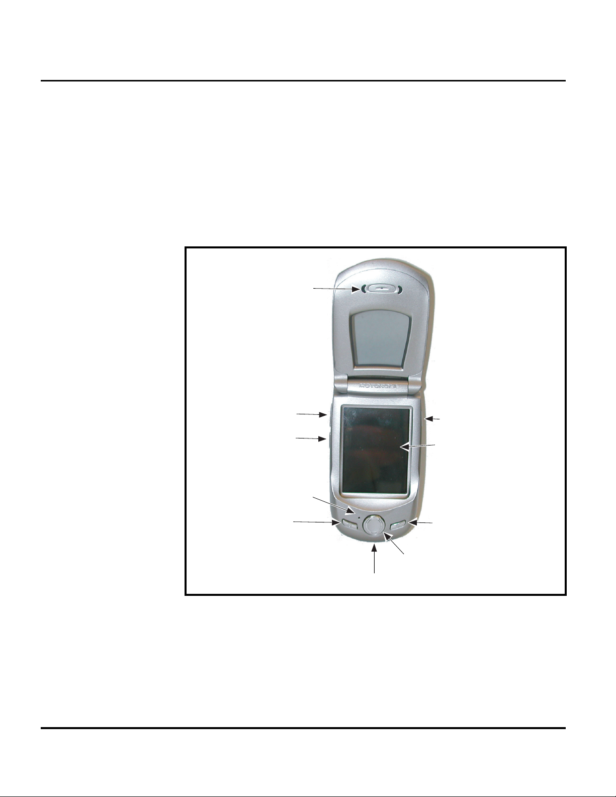
Controls, Indicators, and Input/Output (I/O) Connections
The A760 telephone’s controls are located on the front of the device
(see Figure 1). Controls on the front of the phone include a Power ON/OFF button,
Home Key, and a Up /Down key Soft Menu key on the left and right side. Indicators,
in the form of icons, are displayed on the LCD. Service status is indicated by a tricolor light emitting diode (LED) (not shown) located on top of the phone.
Additionally, I/O connectors consisting of a headset jack and an accessory port are
located on the top and bottom of the phone, respectively. See Figure 1.
Speaker
Volume
Up/Down
Keys
Microphone
Powe r
On/Off
Key
Charger/Accessory
Figure 1. Controls, Indicators, and I/O
Voice Notes
Key
320x240Pixel
Touch screen
Display
Home Key
Page
Up/Down
Key
Por t
020035-o
12 August 26, 2003 6809464A70
Page 13
Level 1 and 2 Service Manual General Operation
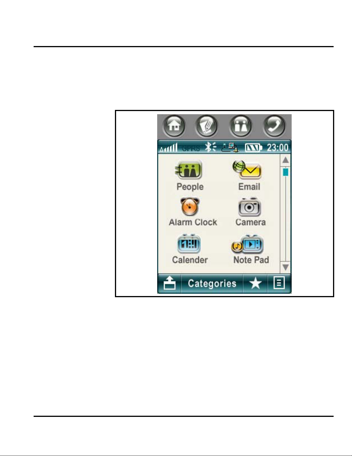
Color Display
The color display provides a high resolution 240x320 touch screen display for easy
readability in all light conditions (see Figure 2).
The screen displays the main menu icons and all of the function group icons. You
can navigate around the touch screen using the stylus to select the desired
functions.
031658o
Figure 2. Sample Menu DIsplay
Display animation makes the phone’s menus move smoothly as the user scrolls up
and down.
➧
6809464A70 August 26, 2003 13
Whether a phone displays all indicators depends on the programming and services
to which the user subscribes.
Page 14
General Operation A760
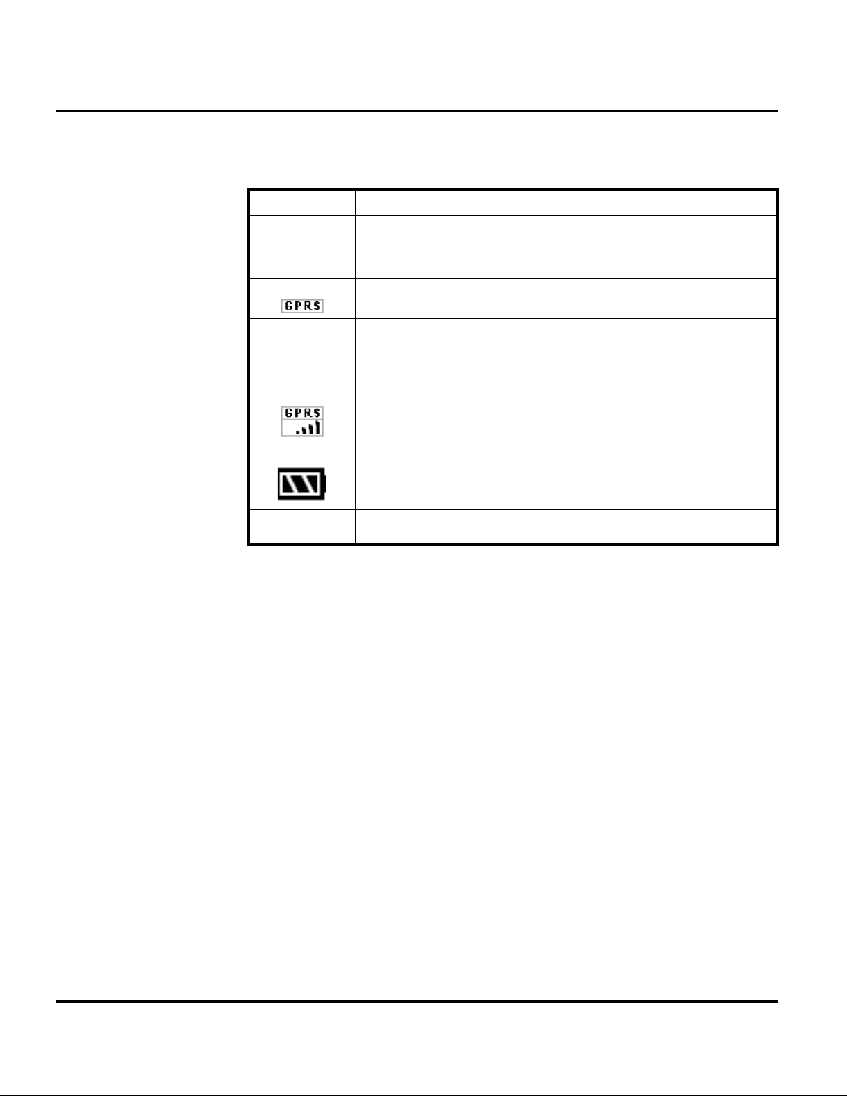
Table 1 shows some common icons displayed on the LCD.
Table 1. Icon Indicators and Description
Icon Description
Signal Strength Indicator. Shows the strength of the phone’s connection with the
network.
GPRS Indicator. Appears when the phone is in GPRS mode.
Bluetooth Indicator. Appears when a bluetooth accessory or device is wirelessly
connected.
GPRS Indicator. Appears when the phone is in GPRS mode.
12:26
Battery Level Indicator. Shows the amount of charge left in the battery. The more
segments visible, the greater the charge. Recharge the battery as soon as possible
when the Low Battery warning message appears.
Clock. Shows the current time. This is a network-dependent feature.
14 August 26, 2003 6809464A70
Page 15

Level 1 and 2 Service Manual General Operation
Menu Navigation
A760 telephones are equipped with a new user-friendly interface that employs 6
main menus.
• Communication
•Organize
•Play
• Tools
•Extras
• Personal
Icons along the top row of the display provide quick access to selected applications.
Select each menu or application by tapping the icon on the screen. Each menu
contains application icons that make up a function group.
Communication
Phone
Address book
Message Center
Recent Calls
Email
Browser
STK
Organize
Calendar
Tasks
Note pad
File manager
Play
Camera
Media Player
Drawing/Ani pad
Voice Recorder
Personal
Tools
Network connection
Sync
Modem
Bluetooth
VPN
Security
Car kit
System setup
Extras
World time
Alarm clock
Calculator
Figure 3. Menu Navigation
6809464A70 August 26, 2003 15
Page 16

General Operation A760
Alert Settings
A760 telephones include up to 32 preset alert tones and vibrations that can be
applied to all alert events at the same time.
Battery Function
G
➧
➧
Pressing either volume key will mute the alert.
Battery Gauge
The telephone displays a battery level indicator icon in the idle screen to indicate
the battery charge level. The gauge shows four levels: 100%, 66%, 33%, and Low
Battery.
Battery Removal
Removing the battery causes the device to immediately shut down and any pending
work (for example, partially entered phone book entries or outgoing messages) is
lost.
To ensure proper memory retention, turn OFF the phone before removing the
battery. Immediately replace the old battery with a fresh battery.
If the battery is removed while receiving a message, the message will be lost.
Operation
For detailed operating instructions, refer to the appropriate User Guide listed in
the Related Publications section toward the end of this manual.
16 August 26, 2003 6809464A70
Page 17

1 and 2
Level 1 and 2 Service Manual Tools and Test Equipment
6809464A70
A760
Tools and Test Equipment
The following table lists tools and test equipment recommended for disassembly
and reassembly of A760 telephones. Use either the listed items or equivalent.
Table 2. General Test Equipment and Tools
Motorola Part Number
RSX4043-A Torque Driver Used to remove and replace screws
1
Description Application
—
See Table 6 Charger
0180386A82
6680388B67
6680388B01 Tweezers, plastic Used during assembly/disassembly
2
—
3
—
8102430Z04 GSM / DCS Test SIM Card Used to enable manual test mode
1. To order in North America, contact Motorola Aftermarket and Accessories Division (AAD) at (847) 538-8000;
Internationally, AAD can be reached by calling +1 847 5388023 or faxing +1 847 5763023.
2. Not available from Motorola. To order, contact Plato Products, Inc. at (626) 965-8044.
3. Not available from Motorola. To order, contact Hewlett Packard at (800) 452-4844.
Torque Driver Bit T-6 Plus, Apex 440-6IP
Torx Plus or equivalent
Antistatic Mat Kit (includes 66-80387A95
antistatic mat, 66-80334B36 ground
cord, and 42-80385A59 wrist band)
Disassembly tool, plastic with flat and
pointed ends
Tweezers, stainless steel, Type 2
pointed blade, Plato part number
TZF-401-2 or equivalent
Digital Multimeter, HP34401A Used to measure battery voltage
Used with torque driver
Used to charge battery and to power
device
Provides protection from damage to
device caused by electrostatic discharge
(ESD)
Used during assembly/disassembly of
device
Used for flip removal.
6809464A70 August 26, 2003 17
Page 18

Disassembly A760
Disassembly
The procedures in this section provide instructions for the disassembly of a A760
telephone. Tools and equipment used for the phone are listed in Table 2, preceding.
Many of the integrated devices used in this equipment are vulnerable to damage
G
G
Removing and Replacing the Battery Door
from electrostatic discharge (ESD). Ensure adequate static protection is in place
when handling, shipping, and servicing the internal components of this equipment.
Avoid stressing the plastic in any way to avoid damage to either the plastic or
internal components.
1. Ensure the phone is turned off.
2. Press the battery door release latch on the rear of the phone at the bottom end
(see Figure 4).
3. Slide the battery door toward the bottom end of the phone.
4. Lift the battery door up and away from the phone.
Battery Door
Figure 4. Removing and Replacing the Battery Door
5. To replace, align the battery door with the rear housing.
6. Lower the battery door onto the rear housing and slide the battery door toward
the antenna to lock. The battery door latch will snap into position.
Removing and Replacing the Battery Door
1. Remove the Battery door by pushing down on battery door latch and sliding
battery door down and away from the phone (see Figure 5).
2.
Battery Door
Latch
031708o
18 August 26, 2003 6809464A70
Page 19

Level 1 and 2 Service Manual Disassembly
Removing and Replacing the Battery
All batteries can cause property damage and/or bodily injury such as burns if a
conductive material such as jewelry, keys, or beaded chains touch exposed terminals.
E
The conductive material may complete an electrical circuit (short circuit) and
become quite hot. Exercise care in handling any charged battery, particularly when
placing it inside a pocket, purse, or other container with metal objects.
1. Ensure the phone is turned off.
1. Press down on the top of the battery to compress the battery contacts
2. Pull up and away from rear Housing.
3. lift the end of the battery and remove it completely. See Figures 5-2 and 5-3.
Battery
031709o
Figure 5. Removing the battery
There is a danger of explosion if the Lithium Ion battery is replaced incorrectly.
Replace only with the same type of battery or equivalent as recommended by the
E
6809464A70 August 26, 2003 19
battery manufacturer. Dispose of used batteries according to the manufacturer’s
instructions.
4. To replace, align the battery with the battery compartment so the contacts on
the battery match the battery contacts in the phone.
5. Insert the tabs at the base of the battery into the slots at the bottom of the
battery compartment.
6. Push the top of the battery down until it snaps into place.
Page 20

Disassembly A760
Removing and Replacing the Subscriber Identity Module (SIM)
1. Remove the battery door, and battery as described in the procedures.
2. Slide the SIM in the direction of the arrow (see Figure 6) to remove the SIM.
3. To replace, insert the SIM into the holder, ensuring the keyed corner of the
SIM aligns with the notch molded into the holder.
SIM
031712o
Figure 6. Removing the SIM
4. To replace, insert the SIM into the holder, ensuring the keyed corner of the
SIM aligns with the notch molded into the rear housing.
5. Replace the battery, and battery door as described in the procedures.
20 August 26, 2003 6809464A70
Page 21

Level 1 and 2 Service Manual Disassembly
Removing and Replacing the Stylus
1. Grasp the stylus and pull it straight out of the top of the telephone as shown
in Figure 7.
Stylus
031713o
Figure 7. Removing the stylus
2. To replace, insert the stylus, pointed end first, into the styles holder on the top
of the telephone. Push until fully seated in the holder.
6809464A70 August 26, 2003 21
Page 22

Disassembly A760
Removing and Replacing the Antenna
1. Remove the battery door, and battery as described in the procedures.
2. By hand, rotate the antenna counterclockwise until loose as shown in
Figure 8-1.
1
2
G
031714o
Figure 8. Removing the antenna
3. When the antenna threads are completely disengaged, pull the antenna
straight out of the phone housing to remove. Figure 8-2.
Ensure antenna threads are properly engaged before tightening to prevent damage
to the antenna or housing.
4. To replace, insert the threaded end of the antenna carefully into the housing
and, after ensuring the threads are properly engaged, rotate clockwise. Tighten
firmly by hand.
5. Replace the battery, and battery door as described in the procedures.
22 August 26, 2003 6809464A70
Page 23

Level 1 and 2 Service Manual Disassembly
Removing and Replacing the Rear Housing
This product contains static-sensitive devices. Use anti-static handling procedures
G
G
to prevent electrostatic discharge (ESD) and component damage.
1. Remove the battery door, stylus, battery, SIM, and antenna as described in the
procedures.
In addition to 4 screws, the rear housing is fastened with 2 plastic catches. The
catches are fragile and should be handled with care.
2. Using a Torx driver with a T-6 bit, remove the 4 screws from the rear housing.
See Figure 9A.
3. With the flat end of the disassembly tool, carefully press the 2 housing catches
inward on each side of the phone to release the rear housing. See Figure 9B.
Housing Latch (each side)
Figure 9. Removing the Rear Housing Screws
Screw, T-6,
4 Places
A
B
031715o
6809464A70 August 26, 2003 23
Page 24

Disassembly A760
4. Lift the rear housing away from the front housing as shown in Figure 10.
Rear Housing
031819o
Figure 10. Removing the Rear Housing
5. To replace, align the housing catches then press the rear housing down until
the 2 housing catches engage. Press the housings together until the catches
snap into place.
6. Replace the 4 screws and tighten securely. Do not over tighten.Reinsert the
ribber screw cap in the screw location near the antenna.
7. Replace the stylus, antenna, SIM, battery, and battery door as described in the
procedures.
24 August 26, 2003 6809464A70
Page 25

Level 1 and 2 Service Manual Disassembly
Removing and Replacing the Transceiver Board
This product contains static-sensitive devices. Use anti-static handling procedures
G
to prevent electrostatic discharge (ESD) and component damage.
1. Remove the battery door, battery, SIM, stylus, antenna, and rear housing as
described in the procedures.
2. Use the metal tweezers to disconnect the speaker wire connector from the
transceiver board (see Figure 11).
3. Carefully lift the transceiver board away from the rear housing.
Transceiver PCB Assembly
Speaker Connector
031718o
Figure 11. Removing the Transceiver Board
4. To replace, insert the transceiver board assembly into the front housing with
the flex connector on top. Be sure the main board assembly is properly seated
on the 4 front housing posts
6809464A70 August 26, 2003 25
Page 26

Disassembly A760
Removing and Replacing the Camera Assembly
1. Remove the battery door, battery, SIM, antenna, stylus, rear housing, and
G
transceiver board as described in the procedures.
The flexible printed cable (FPC or flex) is easily damaged. Exercise extreme care
when handling.
2. Use the disassembly tool to unseat the camera flex connector from its socket
on the transceiver PCB assembly (see Figure 11).
3. Using the metal tweezers, release the two camera assembly latches on each
side of the camera assembly.
4. Lift the camera assembly up and away from the transceiver board.
.
Transceiver PCB Assembly
Camera Assembly Latches
Camera Assembly
Camera Flex Connector
Camera Assembly Latches
031719o
Figure 12. Removing the Camera Assembly
26 August 26, 2003 6809464A70
Page 27

Level 1 and 2 Service Manual Disassembly
5. To replace, align the camera assembly to the transceiver PCB assembly.
6. Place the camera assembly onto the transceiver PCB assembly.
7. Use the metal tweezers to secure the camera latches on each side of the camera
assembly.
8. Connect the camera flex connector to the socket on the transceiver PCB
assembly.
9. Replace the transceiver PCB assembly, rear housing, antenna, stylus, SIM,
battery, and battery door as described in the procedures.
Removing and Replacing the Real Time Clock (RTC) Battery
1. Remove the battery door, battery, SIM, stylus, antenna, rear housing, and
transceiver board as described in the procedures
.
RTC Battery
031752o
Figure 13. Removing the RTC battery
2. Using the flat end of the disassembly tool, gently pry the RTC battery from its
socket on the transceiver board. See Figure 13.
Use only non-conductive tools, such as the plastic disassembly tool and the plastic
G
6809464A70 August 26, 2003 27
tweezer, when removing and replacing the RTC battery.
3. To replace, insert the new RTC battery into its socket on the main board. The
plastic tweezer may be used to replace the RTC battery. Be sure the positive
battery terminal is up (facing away from the board) and the battery is
completely seated in its socket.
4. Replace the rear housing, antenna, SIM, and battery as described in the
procedures.
Page 28

Disassembly A760
Removing and Replacing the Keypad
1. Remove the battery, SIM, antenna, rear housing, and main board as described
in the procedures
2. Lift the keypad from the front housing as shown in Figure 14.
.
Front Housing
Disassembly Tool
Figure 14. Removing the Keypad
3. To replace, insert the keypad into the front housing. Make sure they align
properly with the openings in the front housing.
4. Replace the main board, rear housing, antenna, SIM, and battery as described
in the procedures.
5. After reassembly, operate all the keypad keys to verify correct function.
Keypad
031736o
28 August 26, 2003 6809464A70
Page 29

Level 1 and 2 Service Manual Disassembly
Removing and Replacing the Touch Screen Display Assembly
This product contains static-sensitive devices. Use anti-static handling procedures
G
to prevent electrostatic discharge (ESD) and component damage.
1. Remove the battery, SIM, antenna, rear housing, transceiver board, as
described in the procedures
2. Remove the switchdome PCB assembly as shown in Figure 15.
.
Switchdome PCB
Transceiver PCB
031738o
Figure 15. Removing the Switchdome PCB
3. Use the plastic tweezers to move the snubber away from the PCB.
6809464A70 August 26, 2003 29
Page 30

Disassembly A760
4. Use the disassembly tool to unseat the display flex connector from its socket
on the transceiver board (see Figure 16).
Touch Display screen
Touch Display flex Connector
G
Touch Display flex
Figure 16. Removing the Touch Screen Display Flex
5. Carefully lift the touch screen display assembly straight up and away from the
front housing as shown in Figure 15.
The touch screen display is fragile. Do not twist, pry, or drop the assembly during
removal and reassembly.
30 August 26, 2003 6809464A70
Page 31

Level 1 and 2 Service Manual Disassembly
Touch Display screen
Transceiver PC Board
031740o
Figure 17. Removing the Touch Screen Display
6. To replace, lower the touch screen display onto the transceiver board.
7. Align the touch screen display flex connector with the flex connector socket and
carefully press the flex connector into the socket. into 4 posts inside the front
housing and set in place.
8. Place the snubber between the touch screen display flex and the transceiver
board.
9. Place the switchdome PCB onto the transceiver board. Carefully press the
board socket connector into the connector socket
10. Replace the keypad, transceiver board, rear housing, antenna, SIM, battery,
and battery door as described in the procedures.
6809464A70 August 26, 2003 31
Page 32

Disassembly A760
Removing and Replacing the Microphone
1. Remove the battery door, battery, SIM, antenna, rear housing, main board,
and switchdome PCB as described in the procedures
.
Switchdome
PCB
Microphone
Microphone Boot
031751o
Figure 18. Removing the microphone
2. Lift the microphone boot off of the microphone.
3. Observe the orientation of the microphone before removing.
4. Using the plastic tweezers, carefully pull the microphone straight out of the
switchdome PCB as shown in Figure 18.
The microphone connector pins are easily bent or broken. Exercise care when
➧
replacing the microphone.
5. To replace, insert the microphone connector pins into the switchdome PCB
socket and press until the microphone is seated flat against the board. Be sure
to observe proper orientation when replacing the microphone.
6. Replace the switchdome PCB, main board, rear housing, antenna, SIM, and
battery, and battery door as described in the procedures.
32 August 26, 2003 6809464A70
Page 33

Level 1 and 2 Service Manual SIM Cards and Identification
SIM Cards and Identification
SIM Card
A SIM card is required to access the existing local GSM network and remote
networks when traveling.
The SIM card contains:
• All the data necessary to access GSM services.
• The ability to store user information such as phone numbers.
• All information required by the network provider to provide access to the
network.
Personality Transfer
A personality transfer is required when a phone is Express Exchanged or when the
main board is replaced. Personality transfers reproduce the customer's original
personalized details such as menu and stored memory such as phone books, or even
just program a unit with basic user information such as language selection.
Identification
Personality transfers performed at levels 1 and 2 service centers include only the
➧
information stored on the SIM.
Each Motorola GSM device is labeled with a variety of identifying numbers. The
following information describes the current identifying labels.
Mechanical Serial Number (MSN)
The Mechanical Serial Number (MSN) is an individual unit identity number and
remains with the unit throughout the life of the unit.
The MSN can be used to log and track a unit on Motorola's Service Center Database.
The MSN is divided into 4 sections as shown in Figure 19.
MSN 10 Digits
3 Digits 1 Digit 2 Digits 4 Digits
APC DC DC SNR
Account Product Code
i.e. StarTAC Phone130
TM
Distribution Center
i.e. Easter Inch
Date Code: Year and
Month of Shipment
Unit's individual serial
number
000807a
Figure 19. MSN Label
6809464A70 August 26, 2003 33
Page 34

SIM Cards and Identification A760
International Mobile Station Equipment Identity (IMEI)
The International Mobile station Equipment Identity (IMEI) number is an
individual number unique to the PCB and is stored within the unit's memory.
The IMEI uniquely identifies an individual mobile station and thereby provides a
means for controlling access to GSM networks based on mobile station types or
individual units. The full IMEI structure is listed in Table 3.
Table 3. IMEI Number Breakdown
TAC Serial Number Check Digit
NNXXXX YY ZZZZZZ A
Where
TAC Type Allocation Code, formerly known as Type Approval Code
NN Reporting body identifier
XXXX Type Identifier
YY YY is set to 00 from 01/01/2003 until 31/03/2004
ZZZZZZ Individual unit serial number
A Phase 1 = 0.
Phase 2 = check digit defined as a function of all other IMEI digits
Other label number configurations present are:
• TRANSCEIVER NUMBER: Identifies the product type. Normally the SWF
number. (i.e. V100).
• PACKAGE NUMBER: Identifies the equipment type, mode, and language in
which the product is shipped.
34 August 26, 2003 6809464A70
Page 35

Level 1 and 2 Service Manual Troubleshooting
Troubleshooting
Manual Test Mode
Motorola A760 telephones are equipped with a manual test mode capability. This
allows service personnel to verify functionality and perform fault isolation by
entering keypad commands.
To enter the manual test command mode, a GSM/DCS test SIM must be used.
1. Press , to turn the phone OFF.
2. Remove the battery as described in the procedures.
3. Remove the customer’s SIM card from the phone as described in the
procedures.
4. Insert the test SIM into the SIM slot.
5. Replace the battery as described in the procedures.
6. Press , to turn the phone ON.
Press and hold the # button for approximately 3 seconds until TEST displays on the
screen. The phone may now be issued test commands listed in Table 4.
Manual Test Mode Commands
Table 4. Test Commands
Test Command Test Function/Name
Press and hold # for 2 seconds Enter manual test mode
01# Exit manual test mode
07x# Mute RX audio path
08# Unmute RX audio path
09# Mute TX audio path
10# Unmute TX audio path
15x# Generate tone
1590# Vibrate Mode
1591# Ringer Mode
16# Mute tone generator
19# Display software version number of Call Processor
20# Display software version number of Modem
36# Initiate acoustic loopback
360# Full Rate
361# Enhanced Full Rate
362# Half Rate
37# Stop test
38# Activate Mini SIM
39# Deactivate Mini SIM
43x# Change audio path
47x# Set audio volume
51# Enable sidetone
6809464A70 August 26, 2003 35
Page 36

Troubleshooting A760
Table 4. Test Commands (Continued)
Test Command Test Function/Name
52# Disable sidetone
54# Show service indicator LED (0 - Off, 1 - Red, 2 - Green, 3 - Amber) (flip must be closed)
57# Initialize non-volatile memory
58# Display security code
58xxxxxx# Modify security code
59# Display lock code
59xxx# Modify lock code
60# Display IMEI
980# DCS Mode (PF B95 only)
981# GSM Mode (PF B95 only)
962# PCS Mode (PF C21 only)
99# Display all pixels
Troubleshooting Chart
Table 5. Product Family 0C45 Telephone: Level 1 and 2 Troubleshooting Chart
SYMPTOM PROBABLE CAUSE VERIFICATION AND REMEDY
1. Telephone will not turn on or stay on. a) Battery either discharged or
2. Telephone exhibits poor reception or
erratic operation such as calls frequently
dropping or weak or distorted audio.
3. Display is erratic, or provides partial or
no display.
defective.
b) Battery connectors open or
misaligned.
c) Main board assembly defective. Remove the main board assembly. Substitute a
a) Antenna assembly defective. Check to make sure that the antenna pin is
b) Main board assembly defective. Replace the main board assembly (refer to 1c).
a) Main board connections faulty. Remove rear housing from unit, check general
Measure battery voltage across a 50 ohm (>1
Watt) load. If the battery voltage is <3.25 Vdc,
recharge the battery using the appropriate
battery charger. If the battery will not recharge,
replace the battery. If battery is not at fault,
proceed to b.
Visually inspect the battery connectors on both
the battery and the telephone. Realign and, if
necessary, either replace the battery or refer to
a Level 3 Service Center for the battery
connector replacement. If battery connectors
are not at fault, proceed to c.
known good assembly and temporarily
reassemble the unit. Depress the PWR button; if
unit turns on and stays on, disconnect the dc
power source and reassemble the telephone
with the new main board assembly. Verify that
the fault has been cleared.
properly connected to the main board assembly.
If connected properly, substitute a known good
antenna. If the fault is still present, proceed to b.
Verify that the fault has been cleared and
reassemble the unit with the new main board
assembly.
condition of flexible printed cable (flex). If the flex
is good, check that the flex connector is properly
locked. If faulty connector, replace the main
board assembly. If connector is not at fault,
proceed to b.
36 August 26, 2003 6809464A70
Page 37

Level 1 and 2 Service Manual Troubleshooting
Table 5. Product Family 0C45 Telephone: Level 1 and 2 Troubleshooting Chart (Continued)
SYMPTOM PROBABLE CAUSE VERIFICATION AND REMEDY
4. Incoming call alert transducer audio
distorted or volume is too low.
5. Telephone transmit audio is weak.
(usually indicated by called parties
complaining of difficulty in hearing voice).
6. Receive audio from earpiece speaker is
weak or distorted.
7. Telephone will not recognize or accept
SIM card.
b) Touch screen display assembly
defective.
c) Main board assembly defective. Replace the main board assembly (refer to 1c).
Faulty alert transducer or main board
assembly.
a) Microphone connections to the
main board assembly defective.
b) Microphone defective. Gain access to microphone. Disconnect and
c) Main board assembly defective. Replace the main board assembly (refer to 1c).
a) Connections to or from main board
assembly defective.
b) Earpiece speaker defective. Replace the flip assembly as described in the
c) Antenna assembly defective. Check to make sure the antenna is installed
d) Main board assembly defective. Replace the main board assembly (refer to 1c).
a) SIM card defective. Check the SIM card contacts for dirt. Clean if
Remove the touch screen display assembly as
described in the procedures. Temporarily
reassemble unit with a known good touch
screen display assembly and verify proper
operation. If fault is cleared, reassemble unit
with the new assembly. If fault not cleared,
proceed to c.
Verify that the fault has been cleared and
reassemble the unit with the new main board
assembly.
Replace the main board assembly (refer to 1c).
Verify that the fault has been cleared and
reassemble the unit with the new main board
assembly.
Gain access to the microphone as described in
the procedures. Check connections. If connector
is faulty proceed to c; if the connector is not at
fault, proceed to b.
substitute a known good microphone. Place a
call and verify improvement in transmit signal as
heard by called party. If good, reassemble with
new microphone. If microphone is not at fault,
reinstall original microphone and proceed to c.
Verify that the fault has been cleared and
reassemble the unit with the new main board
assembly.
Gain access to the main board assembly as
described in the procedures. Check the speaker
leads and connector from the flip assembly to
the main board assembly. If speaker leads are at
fault, replace the flip assembly. If connector is at
fault, proceed to d. If connection is not at fault,
proceed to b.
procedures. Temporarily reassemble unit and
verify proper operation. If fault has not been
cleared, replace original flip assembly and
proceed to proceed to c.
correctly. If the antenna is installed correctly,
substitute a known good antenna assembly. If
this does not clear the fault, reinstall the original
antenna assembly and proceed to d.
Verify that the fault has been cleared and
reassemble with the new main board assembly.
necessary and check if fault has been cleared. If
the contacts are clean, insert a known good SIM
card into the telephone. Power up the unit and
confirm that the card has been accepted. If the
fault no longer exists, replace the defective SIM
card. If the SIM card is not at fault, proceed to b.
6809464A70 August 26, 2003 37
Page 38

Troubleshooting A760
Table 5. Product Family 0C45 Telephone: Level 1 and 2 Troubleshooting Chart (Continued)
SYMPTOM PROBABLE CAUSE VERIFICATION AND REMEDY
b) Connections between touch screen
display assembly and main board
assembly faulty.
c) Touch screen display assembly
defective.
d) Main board assembly defective. Replace the main board assembly (refer to 1c).
8. Phone does not sense when flip is
opened or closed (usually indicated by
inability to answer incoming calls by
opening the flip, or inability to make
outgoing calls).
9. Vibrator feature not functioning. Vibrator on main board defective. Replace the main board assembly (refer to 1c).
10. Internal Charger not working. Faulty charger circuit on main board
11. Real Time Clock resetting when
standard battery is removed.
12. No or weak audio when using headset. a) Headset not fully pushed home. Ensure the headset plug is fully seated in the
a) Magnet in flip assembly missing or
defective.
b) Sensor on main board defective. Replace the main board assembly (refer to 1c).
assembly.
Lithium Ion RTC battery on the main
board may be depleted.
b) Faulty jack socket on main board
assembly.
Refer to remedy 3a and 3b. If fault has not been
cleared, proceed to c.
Replace touch screen display assembly with a
known good one. Temporarily reassemble unit
and verify proper operation. If fault has not been
cleared, replace original touch screen display
assembly and proceed to d.
Verify that the fault has been cleared and
reassemble the unit with the new main board
assembly.
Replace flip assembly with known good one.
Refer to the procedures. Place call to phone and
verify ability to answer by opening flip. If fault is
cleared, rebuild phone with new flip assembly. If
fault is still present, replace original flip
assembly and proceed to b.
Verify that the fault has been cleared and
reassemble the unit with the new main board
assembly.
Verify that the fault has been cleared and
reassemble the unit with the new main board
assembly.
Test a selection of batteries in the rear pocket of
the desktop charger. Check LED display for the
charging indications. If these are charging
properly, then the internal charger is at fault.
Replace the main board assembly (refer to 1c).
Verify that the fault has been cleared and
reassemble the unit with the new main board
assembly.
Replace the RTC battery as described in the
procedures. Check RTC time does not reset.
jack socket.
Replace the main board assembly (refer to 1c).
Verify that the fault has been cleared and
reassemble the unit with the new main board
assembly.
38 August 26, 2003 6809464A70
Page 39

Level 1 and 2 Service Manual Troubleshooting
Programming: Software Upgrade and Flexing
Contact your local technical support engineer for information about equipment and
procedures for flashing and flexing.
Part Number Charts
The following charts are provided as a reference for the parts associated with
A760 telephones.
Related Publications
Motorola A760 Wireless Phone User Guide, Simple Chinese 6809455A38
Motorola A760 Wireless Phone User Guide, Traditional Chinese 6809455A28
Motorola A760 Wireless Phone User Guide, English 6809455A29
Motorola A760 Wireless Phone Quick Start Guide English 6802911J47
6809464A70 August 26, 2003 39
Page 40

Troubleshooting A760
Exploded View Diagram
1
2
3
4
5
7
11
1
8
11
1
9
6
10
11
12
13
14
15
16
031655o
Figure 20. Exploded view diagram
40 August 26, 2003 6809464A70
Page 41

Level 1 and 2 Service Manual Troubleshooting
Exploded View Parts List
Table 6. Exploded View Parts List
Item
Number
1 0104076R01 Flip Assembly
2 5504865R01 Hinge Assembly w/teflon
3 0104075R01 Front Housing Assembly
4 0164092E01 Center Band Assembly
5 7287603N01 TFT Color Display Assembly
6 5087974K02 Microphone
7 CHLF4369 Transceiver Main Board
8 0164099E01 Camera Assembly
9 8504802R01 Stub Antenna
10 1504787R01 Rear Housing
11 0364579E02 Screw (4)
12 0504864R01 Screw Cap
13 0504808R01 RF Cap
14 SNN5669 800 mAh Battery PRC
14 SNN5670 800 mAh Battery MULTL
15 1504790R01 Battery Door
16 0164089E01 Stylus Assembly
Note: 1. Not available as spares in EMEA Service markets.
Motorola
Part Number
Description
E
Accessories
Table 7. Accessories
Rapid Charger, PRC
Rapid Charger, UK
Rapid Charger, US
Pouch CHYN4459
Stereo customizable headset SYN0384
Headset, earbud, with send/end key SYN8419
Bluetooth Headset SYN9006
There is a danger of explosion if the Lithium Ion battery is replaced incorrectly. Replace only with
the same type of battery or equivalent as recommended by the battery manufacturer. Dispose of
used batteries according to the manufacturer’s instructions.
Part Description Part Number
SPN5052
SPN5051
SPN5049
6809464A70 August 26, 2003 41
Page 42

Troubleshooting A760
42 August 26, 2003 6809464A70
Page 43

Level Service Manual
A
alert settings 16
antenna, removing and replacing
22
B
battery
function
gauge
removing
replacing
16
16
19, 21
20
C
Canadian Interference-Causing Equipment regulations 5
changes
product
color display (LCD)
commands, manual test mode
controls
conventions
copyrights
computer software
5
13
35
12
7
6
D
disassembly 18
E
exploded view diagram 40
exploded view parts list
41
F
FCC rules 5
features
11
I
identification 33
international mobile station equipment identity
mechanical serial number
product
IMEI
34
Introduction
5
5
33
34
K
keypad, removing and replacing 28
microphone, removing and replacing
MSN
33
N
names
product
5
O
overview 10
P
part numbers
accessories
parts
39
exploded view diagram
exploded view parts list
product
changes
identification
names
publications, related
41
40
41
5
5
5
39
R
rear housing
removing
regulatory agency compliance
related publications
removing
antenna
battery
battery door
keypad
microphone
rear housing
SIM card
replacement parts
ordering
replacing
antenna
battery
battery door
keypad
microphone
revisions
service manual
23
5
39
22
16, 19, 21
18
28
32
23
20
8
22
19, 21
18
28
32
7
32
M
manual test mode 35
S
serial number
September 03, 2002 Index-1
Page 44

mechanical 33
service manual
about
6
revisions
scope
service policy
customer support
out of box failure
product support
replacement parts
shut down
upon battery removal
SIM card
personality transfer
removing
replacing
specifications
support
customer
product
7
6
7
33
20
20
9
8
7
Product Family
8
7
7
8
16
33
T
tools and test equipment 17
troubleshooting
manual test mode
manual test mode commands
35
35
U
user interface diagrams 16
W
warranty service 7
35
Index-2 September 03, 2002
Page 45

Page 46

MOTOROLA, the Stylized M Logo, and all other trademarks indicated as such herein are trademarks of Motorola, Inc.
TrueSync is a trademark of Starfish, Inc., a wholly owned independent subsidiary of Motorola, Inc.
All other product or service names are the property of their respective owners.
® Reg. U.S. Pat. & Tm. Off.
2003 Motorola, Inc.
All rights reserved.
Personal Communications Sector,
789 International Parkway.
Sunrise, FL 33325-6220
@6809464A70@
6809464A70-O
 Loading...