

Page 1

M
Product Family 0C81
Tri-Band Wireless Telephone
Level 1 and 2 Service Manual
GSM 900/1800/1900 MHz & GPRS Technologies
DRAFT
A388c
Page 2

Page 3

1 and 2
Table of Contents
Level 1 and 2 Service Manual Table of Contents
0C81
6809462A54
Introduction . . . . . . . . . . . . . . . . . . . . . . . . . . . . . . . . . . . . . . . . . . . . . . . . . . . . . . . . . . . . . . . . . . . . . . . . . . . . . . . . . 5
Product Identification . . . . . . . . . . . . . . . . . . . . . . . . . . . . . . . . . . . . . . . . . . . . . . . . . . . . . . . . . . . . . . . . . . . 5
Product Names . . . . . . . . . . . . . . . . . . . . . . . . . . . . . . . . . . . . . . . . . . . . . . . . . . . . . . . . . . . . . . . . . . . . . . . . 5
Product Changes . . . . . . . . . . . . . . . . . . . . . . . . . . . . . . . . . . . . . . . . . . . . . . . . . . . . . . . . . . . . . . . . . . . . . . . 5
Regulatory Agency Compliance . . . . . . . . . . . . . . . . . . . . . . . . . . . . . . . . . . . . . . . . . . . . . . . . . . . . . . . . . . . 5
Computer Program Copyrights . . . . . . . . . . . . . . . . . . . . . . . . . . . . . . . . . . . . . . . . . . . . . . . . . . . . . . . . . . . 6
About this Service Manual . . . . . . . . . . . . . . . . . . . . . . . . . . . . . . . . . . . . . . . . . . . . . . . . . . . . . . . . . . . . . . . 6
Warranty Service Policy . . . . . . . . . . . . . . . . . . . . . . . . . . . . . . . . . . . . . . . . . . . . . . . . . . . . . . . . . . . . . . . . . 7
Parts Replacement . . . . . . . . . . . . . . . . . . . . . . . . . . . . . . . . . . . . . . . . . . . . . . . . . . . . . . . . . . . . . . . . . . . . . 8
Specifications . . . . . . . . . . . . . . . . . . . . . . . . . . . . . . . . . . . . . . . . . . . . . . . . . . . . . . . . . . . . . . . . . . . . . . . . . . . . . . 9
Product Overview . . . . . . . . . . . . . . . . . . . . . . . . . . . . . . . . . . . . . . . . . . . . . . . . . . . . . . . . . . . . . . . . . . . . . . . . . . . 10
Features . . . . . . . . . . . . . . . . . . . . . . . . . . . . . . . . . . . . . . . . . . . . . . . . . . . . . . . . . . . . . . . . . . . . . . . . . . . . . 10
General Operation . . . . . . . . . . . . . . . . . . . . . . . . . . . . . . . . . . . . . . . . . . . . . . . . . . . . . . . . . . . . . . . . . . . . . . . . . . . 13
Controls, Indicators, and Input/Output (I/O) Connections . . . . . . . . . . . . . . . . . . . . . . . . . . . . . . . . . . . . . 13
Alert Settings . . . . . . . . . . . . . . . . . . . . . . . . . . . . . . . . . . . . . . . . . . . . . . . . . . . . . . . . . . . . . . . . . . . . . . . . 16
Battery Function . . . . . . . . . . . . . . . . . . . . . . . . . . . . . . . . . . . . . . . . . . . . . . . . . . . . . . . . . . . . . . . . . . . . . . 16
Operation . . . . . . . . . . . . . . . . . . . . . . . . . . . . . . . . . . . . . . . . . . . . . . . . . . . . . . . . . . . . . . . . . . . . . . . . . . . . 16
Tools and Test Equipment . . . . . . . . . . . . . . . . . . . . . . . . . . . . . . . . . . . . . . . . . . . . . . . . . . . . . . . . . . . . . . . . . . . . 17
Disassembly . . . . . . . . . . . . . . . . . . . . . . . . . . . . . . . . . . . . . . . . . . . . . . . . . . . . . . . . . . . . . . . . . . . . . . . . . . . . . . . . 18
Removing and Replacing the Stylus . . . . . . . . . . . . . . . . . . . . . . . . . . . . . . . . . . . . . . . . . . . . . . . . . . . . . . 18
Removing and Replacing the Battery . . . . . . . . . . . . . . . . . . . . . . . . . . . . . . . . . . . . . . . . . . . . . . . . . . . . . 18
Removing and Replacing the Subscriber Identity Module (SIM) . . . . . . . . . . . . . . . . . . . . . . . . . . . . . . . . 20
Removing and Replacing the Antenna . . . . . . . . . . . . . . . . . . . . . . . . . . . . . . . . . . . . . . . . . . . . . . . . . . . . 21
Removing and Replacing the Rear Housing . . . . . . . . . . . . . . . . . . . . . . . . . . . . . . . . . . . . . . . . . . . . . . . . 21
Removing and Replacing the Real Time Clock (RTC) Battery . . . . . . . . . . . . . . . . . . . . . . . . . . . . . . . . . . 23
Removing and Replacing the Alert Gasket . . . . . . . . . . . . . . . . . . . . . . . . . . . . . . . . . . . . . . . . . . . . . . . . . 24
Removing and Replacing the Light Guide . . . . . . . . . . . . . . . . . . . . . . . . . . . . . . . . . . . . . . . . . . . . . . . . . . 25
Removing and Replacing the Battery Latch . . . . . . . . . . . . . . . . . . . . . . . . . . . . . . . . . . . . . . . . . . . . . . . . 26
Removing and Replacing the Main Board . . . . . . . . . . . . . . . . . . . . . . . . . . . . . . . . . . . . . . . . . . . . . . . . . . 27
Removing and Replacing the Microphone . . . . . . . . . . . . . . . . . . . . . . . . . . . . . . . . . . . . . . . . . . . . . . . . . . 29
Removing and Replacing the Keypad and Buttons . . . . . . . . . . . . . . . . . . . . . . . . . . . . . . . . . . . . . . . . . . . 30
Removing and Replacing the Touch Screen Display Assembly . . . . . . . . . . . . . . . . . . . . . . . . . . . . . . . . . 31
Removing and Replacing the Flip Assembly . . . . . . . . . . . . . . . . . . . . . . . . . . . . . . . . . . . . . . . . . . . . . . . . 32
SIM Cards and Identification . . . . . . . . . . . . . . . . . . . . . . . . . . . . . . . . . . . . . . . . . . . . . . . . . . . . . . . . . . . . . . . . . . 34
SIM Card . . . . . . . . . . . . . . . . . . . . . . . . . . . . . . . . . . . . . . . . . . . . . . . . . . . . . . . . . . . . . . . . . . . . . . . . . . . . 34
Personality Transfer . . . . . . . . . . . . . . . . . . . . . . . . . . . . . . . . . . . . . . . . . . . . . . . . . . . . . . . . . . . . . . . . . . . 34
Identification . . . . . . . . . . . . . . . . . . . . . . . . . . . . . . . . . . . . . . . . . . . . . . . . . . . . . . . . . . . . . . . . . . . . . . . . . 34
Troubleshooting . . . . . . . . . . . . . . . . . . . . . . . . . . . . . . . . . . . . . . . . . . . . . . . . . . . . . . . . . . . . . . . . . . . . . . . . . . . . 36
Manual Test Mode . . . . . . . . . . . . . . . . . . . . . . . . . . . . . . . . . . . . . . . . . . . . . . . . . . . . . . . . . . . . . . . . . . . . 36
Manual Test Mode Commands . . . . . . . . . . . . . . . . . . . . . . . . . . . . . . . . . . . . . . . . . . . . . . . . . . . . . . . . . . . 36
Troubleshooting Chart . . . . . . . . . . . . . . . . . . . . . . . . . . . . . . . . . . . . . . . . . . . . . . . . . . . . . . . . . . . . . . . . . 37
Programming: Software Upgrade and Flexing . . . . . . . . . . . . . . . . . . . . . . . . . . . . . . . . . . . . . . . . . . . . . . 40
Part Number Charts . . . . . . . . . . . . . . . . . . . . . . . . . . . . . . . . . . . . . . . . . . . . . . . . . . . . . . . . . . . . . . . . . . . 40
Related Publications . . . . . . . . . . . . . . . . . . . . . . . . . . . . . . . . . . . . . . . . . . . . . . . . . . . . . . . . . . . . . . . . . . . 40
Exploded View Diagram . . . . . . . . . . . . . . . . . . . . . . . . . . . . . . . . . . . . . . . . . . . . . . . . . . . . . . . . . . . . . . . . 41
Exploded View Parts List . . . . . . . . . . . . . . . . . . . . . . . . . . . . . . . . . . . . . . . . . . . . . . . . . . . . . . . . . . . . . . 42
Model-dependent Part Numbers . . . . . . . . . . . . . . . . . . . . . . . . . . . . . . . . . . . . . . . . . . . . . . . . . . . . . . . . . 43
Accessories . . . . . . . . . . . . . . . . . . . . . . . . . . . . . . . . . . . . . . . . . . . . . . . . . . . . . . . . . . . . . . . . . . . . . . . . . . . 43
Index . . . . . . . . . . . . . . . . . . . . . . . . . . . . . . . . . . . . . . . . . . . . . . . . . . . . . . . . . . . . . . . . . . . . . . . . . . . . . . . . . . Index-1
DRAFT
6809462A54 September 03, 2002 3
Page 4

Table of Contents Product Family 0C81
DRAFT
4 September 03, 2002 6809462A54
Page 5

1 and 2
0C81
Level 1 and 2 Service Manual Introduction
6809462A54
Introduction
Motorola® Inc. maintains a worldwide organization that is dedicated to provide
responsive, full-service customer support. Motorola products are serviced by an
international network of company-operated product care centers as well as
authorized independent service firms.
Available on a contract basis, Motorola Inc. offers comprehensive maintenance and
installation programs that enable customers to meet requirements for reliable,
continuous communications.
To learn more about the wide range of Motorola service programs, contact your local
Motorola products representative or the nearest Customer Service Manager.
Product Identification
Motorola products are identified by the model number on the housing. Use the entire
model number when inquiring about the product. Numbers are also assigned to
chassis and kits. Use these numbers when requesting information or ordering
replacement parts.
Product Names
Product names included in Product Family 0C81 (A388c) telephones are listed on
the front cover. Product names are subject to change without notice. Some product
names, as well as some frequency bands, are available only in certain markets.
Product Changes
When electrical, mechanical or production changes are incorporated into Motorola
products, a revision letter is assigned to the chassis or kit affected, for example:
-A, -B, or -C.
The chassis or kit number, complete with revision number is imprinted during
production. The revision letter is an integral part of the chassis or kit number and
is also listed on schematic diagrams and printed circuit board layouts.
Regulatory Agency Compliance
This device complies with Part 15 of the FCC Rules. Operation is subject to the
following conditions:
1. This device may not cause any harmful interference, and
2. must accept interference received, including interference that may cause
undesired operation.
This class B device also complies with all requirements of the Canadian
Interference-Causing Equipment Regulations (ICES-003).
Cet appareil numérique de la classe B respecte toutes les exigences du Règlement
sur le matériel brouilleur du Canada.
DRAFT
6809462A54 March 21, 2003 5
Page 6

6809462A54
0C81
Introduction Product Family 0C81
1 and 2
Computer Program Copyrights
The Motorola products described in this manual may include Motorola computer
programs stored in semiconductor memories or other media that are copyrighted
with all rights reserved worldwide to Motorola. Laws in the United States and other
countries preserve for Motorola, Inc. certain exclusive rights to the copyrighted
computer programs, including the exclusive right to copy, reproduce, modify,
decompile, disassemble, and reverse-engineer the Motorola computer programs in
any manner or form without Motorola's prior written consent. Furthermore, the
purchase of Motorola products shall not be deemed to grant either directly or by
implication, estoppel, or otherwise, any license or rights under the copyrights,
patents, or patent applications of Motorola, except for a nonexclusive license to use
the Motorola product and the Motorola computer programs with the Motorola
product.
About this Service Manual
Using this service manual and the suggestions contained in it assures proper
installation, operation, and maintenance of A388c telephones. Refer questions
about this manual to the nearest Customer Service Manager.
A product family is the group of products having the same account product code
(APC). To locate the APC on a device, refer to “Mechanical Serial Number (MSN)”
later in this manual.
Audience
This manual aids service personnel in testing and repairing A388c telephones.
Service personnel should be familiar with electronic assembly, testing, and
troubleshooting methods, and with the operation and use of associated test
equipment.
Use of this manual assures proper installation, operation, and maintenance of
Motorola products and equipment. It contains all service information required for
the equipment described and is current as of the printing date.
Scope
The scope of this document is to provide the basic information relating to A388c
telephones, and also to provide procedures and processes for repairing the units at
Level 1 and 2 service centers including:
•Unit swap out
• Repairing of mechanical faults
• Basic modular troubleshooting
• Testing and verification of unit functionality
• Initiate warranty claims and send faulty modules to Level 3 or 4 repair centers
DRAFT
6 March 21, 2003 6809462A54
Page 7

Level 1 and 2 Service Manual Introduction
Conventions
Special characters and typefaces, listed and described below, are used in this
manual to emphasize certain types of information.
➧
G
E
M
Revisions
Any changes that occur after manuals are printed are described in publication
revision bulletins (PMRs). These bulletins provide change information that can
include new parts listing data, schematic diagrams, and printed circuit board
layouts.
Note: Emphasizes additional information pertinent to the subject
matter.
Caution: Emphasizes information about actions that may result in
equipment damage.
Warning: Emphasizes information about actions that may result in
personal injury.
Keys to be pressed are represented graphically. For example, instead of “Press
the Enter Key”, you will see “Press
Information from a screen is shown in text as similar as possible to what
appears in the display. For example, ALERTS or ALERTS or ALERTS.
Information that you need to type is printed in boldface type
M”.
Warranty Service Policy
The product comes with the standard 12-month warranty terms and conditions.
Accidental damage, misuse, and extended warranties offered by retailers are not
supported under warranty. Non warranty repairs are available at agreed fixed
repair prices.
Out of Box Failure Policy
The standard out of box failure criteria applies. Customer units that fail very early
on after the date of sale, are to be returned to Manufacturing for root cause analysis,
to guard against epidemic criteria. Manufacturing will bear the costs of early life
failure.
Product Support
Customer’s original units will be repaired but not refurbished as standard.
Appointed Motorola Service Hubs will perform warranty and non-warranty field
service for level 2 (assemblies) and level 3 (limited PCB component). The Motorola
High Tech Centers will perform level 4 (full component) repairs.
DRAFT
6809462A54 March 21, 2003 7
Page 8

Introduction Product Family 0C81
Customer Support
Customer support is available through dedicated Call Centers and in-country help
desks. Product Service training should be arranged through the local Motorola
Support Center.
Ordering Replacement Parts
Only centers authorized to carry out repairs can purchase spare parts. Orders for
spare parts from hubs and Hi-Tech Centers should be placed with the regional
Motorola Parts Distribution Center.
Parts Replacement
When ordering replacement parts or equipment, include the Motorola part number
and description used in the service manual or supplement.
When ordering crystals or channel elements, specify the Motorola part number,
description, crystal frequency, and operating frequency desired.
When the Motorola part number of a component is not known, use the product model
number or other related major assembly along with a description of the related
major assembly and of the component in question.
In the U.S.A., to contact Motorola, Inc. on your TTY, call: 800-793-7834
Accessories and Aftermarket Division (AAD)
Replacement parts, test equipment, and manuals can be ordered from AAD.
U.S.A. Outside U.S.A.
Phone: 800-422-4210 Phone: 847-538-8023
FAX: 800-622-6210 FAX: 847-576-3023
To order spare parts in EMEA region call +44 131 479 1274.
To order spare parts in Asia region call +65 648 62995.
DRAFT
8 March 21, 2003 6809462A54
Page 9
Level 1 and 2 Service Manual Specifications
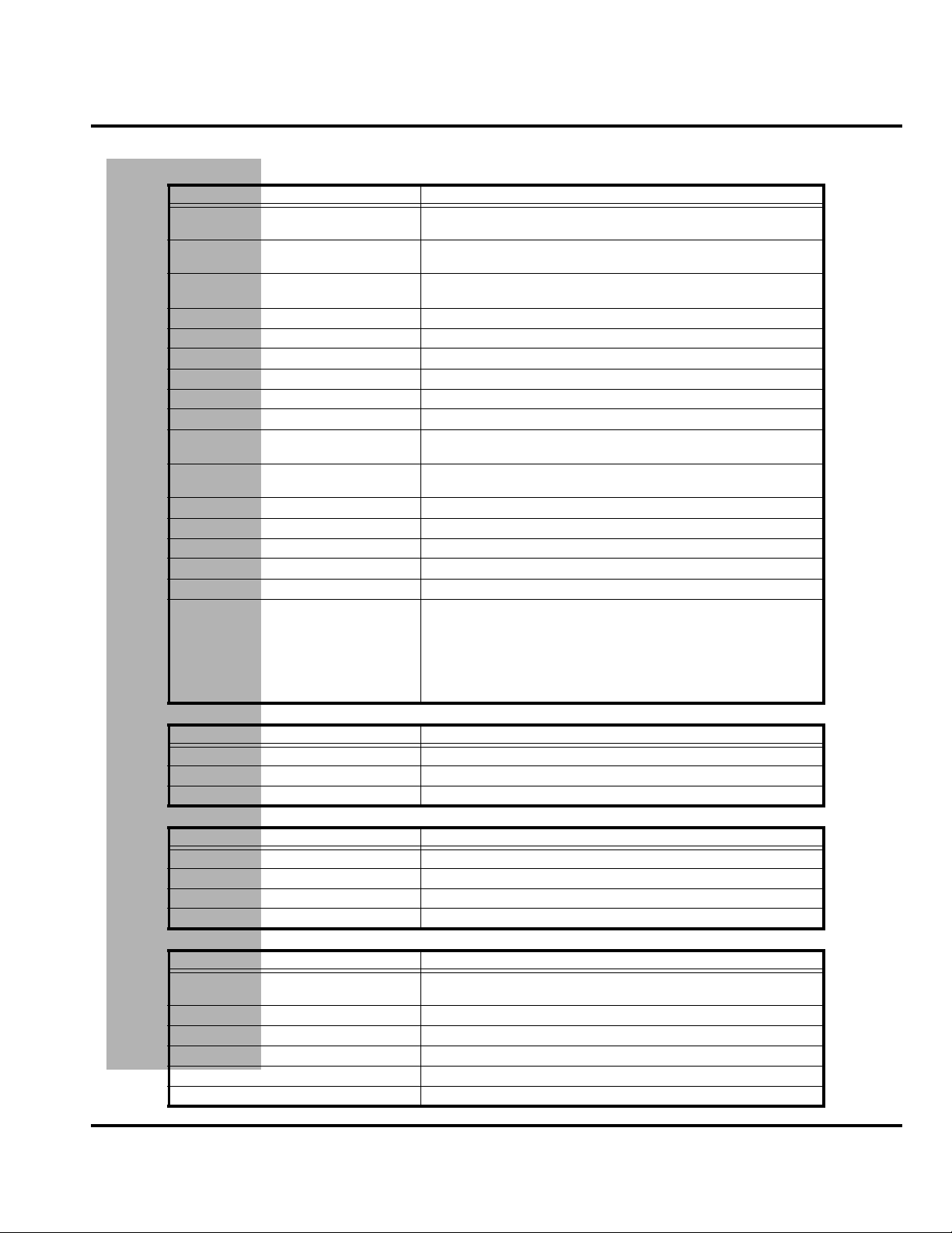
Specifications
General Function Specification
Frequency Range GSM
Frequency Range DCS
Frequency Range PCS
Channel Spacing 200 kHz
Channels 174 EGSM, 374 DCS, 274 PCS carriers with 8 ch. per carrier
Modulation GMSK at BT = 0.3
Transmitter Phase Accuracy 5 Degrees RMS, 20 Degrees peak
Duplex Spacing 45 MHz GSM, 95 MHz DCS, 80 MHz PCS
Frequency Stability ± 0.10 ppm of the downlink frequency (Rx)
Operating Voltage
Transmit Current
Stand-by Current Typically 4.4 mA (DRX2), 8.3 mA (DXR9)
Dimensions 98 mm x 58 mm x 24 mm (3.8 inches X 2.3 inches X 0.9 inches)
Size (Volume) 115 cc (6.8 in
Weight 130 gm (4.5 oz)
Temperature Range -10° C to +55° C (+15° F to +130° F)
Battery Life, 800 mAh
Lithium Ion Battery
880-915 MHz Tx (with EGSM)
925-960 MHZ Rx
1710-1785 MHz Tx
1805-1880 MHz Rx
1850.2-1909.8 MHz Tx
1930.2-1989.8 MHz Rx
+3.0V dc to +5.1V dc (battery)
+4.4V dc to +6.5V dc (external connector)
170mA at RF power 15
280mA at RF power 5
3
)
Talk Time 180 to 300 minutes
Standby 95 to 160 hours
All talk and standby times are approximate and depend on
network configuration, signal strength, and features selected.
Standby times are quoted as a range from DRX=2 to DRX=9.
Talk times are quoted as a range from DTX off to DTX on.
Transmitter Function Specification
RF Power Output 33 dBm nominal GSM, 30 dBm nominal DCS / PCS
Output Impedance 50 ohms nominal
Spurious Emissions -36 dBm from 0.1 to 1 GHz, -30 dBm from 1 to 4 GHz
Receiver Function Specification
Receive Sensitivity -105 dBm GSM, -103 dBm DCS, -104 dBm PCS
RX bit error rate (100k bits) Type II < 2%
Channel Hop Time 500 microseconds
Time to Camp Approximately 5-10 seconds
Speech Coding Function Specification
Speech Coding Type
Bit Rate 13.0 kbps
Frame Duration 20 ms
Block Length 260 bits
Classes Class 1 bits = 182 bits; Class 2 bits = 78 bits
Bit Rate with FEC Encoding 22.8 kbps
6809462A54 March 21, 2003 9
DRAFT
Regular pulse excitation / linear predictive coding with long
term prediction (RPE LPC with LTP)
Page 10

Product Overview Product Family 0C81
Product Overview
Motorola A388c telephones are global system for mobile communications (GSM)
general packet radio service (GPRS) wireless application protocol (WAP)-enabled
mobile phones with full-featured personal information manager (PIM)
functionality. The A388c incorporates a large task-based touch screen display user
interface (UI) featuring handwriting recognition for email and short message
service (SMS) text messaging. It is a tri-band phone that allows roaming within the
GSM 900 MHz, digital cellular system (DCS) 1800 MHz, and personal
communications services (PCS) 1900 MHz bands.
A388c telephones support GPRS and SMS in addition to traditional circuit switched
transport technologies. GPRS, where available, provides substantial increases in
mobile data communications performance and efficient use of radio spectrum. Data
transmission rates for GSM networks can potentially increase from the current rate
of 9.6 kbps up to a theoretical maximum of 171.2 kbps. In addition to increased data
rate, GPRS provides a permanent virtual connection to the network. This “always
on” connection is possible because GPRS uses packet data transfer so that, for
example, email can be downloaded in “background mode” without need for the user
to reconnect before requesting a service. This eliminates connection setup delays
and adds convenience and immediacy to data services. The “virtual” nature of this
connection means network resources are not consumed during periods when a user
is not actually sending or receiving data.
Features
A388c telephones have a clam form factor. They are made of a polycarbonate plastic
with the earpiece speaker located in the flip. The flip features a viewing window
that allows a portion of the display to be seen with the flip is closed. The bottom
part of the clam (front housing) contains the touch screen display, main printed
circuit board (PCB), microphone, external accessory connector, infrared (IR)
communications port, and headset jack. Also located in the front housing are the
voice, volume, power, page up, page down, and menu buttons, as well as the battery,
antenna, subscriber identity module (SIM) holder, and status light. A stylus, also
located in the front housing, is provided to aid manipulating the touch screen UI.
The battery and battery door are integrated into a single unit to minimize overall
phone thickness. The phone accepts both 3V and 5V mini SIM cards which fit into
the SIM holder beneath the battery. The antenna is a fixed stub type antenna. The
service indicator (status light) displays flashing green while in-service, flashing
amber when roaming, flashing red while out of service, and alternating red / green
when ringing.
A388c telephones use advanced, self-contained, sealed, custom integrated circuits
to perform the complex functions required for GSM GPRS communication. Aside
from the space and weight advantage, microcircuits enhance basic reliability,
simplify maintenance, and provide a wide variety of operational functions.
Features available in this family of telephones include:
• Lower voltage technology that provides increased standby and talk times
• Extended GSM (EGSM) channels
• Tri-coder/decoder (CODEC) that allows full rate, half rate, and enhanced full
rate modes of transmission
DRAFT
• Supports SMS, concatenated SMS, and cell broadcast messages
• Supports GPRS, circuit switched, and SMS networks
• Supports POP3, IMAP4, MIME and SMPT email protocols
10 March 21, 2003 6809462A54
Page 11

Level 1 and 2 Service Manual Product Overview
• WAP 1.2.1 compliant
• 65K TFT Color touch screen liquid crystal display (LCD)
• Downloadable wallpaper, themes, screensavers and ring tones
• 7MB memory for user data
•J2ME
•VibraCall
• Voice recorder personal memo feature
• Icon driven user interface with handwriting recognition and on-screen
keyboards
• Supports caller ID
• Supports call forwarding for incoming voice, fax, and data calls
• Supports 3V and 5V SIM cards
• SIM Toolkit (STK), Class II
• Supports TrueSync
Speaker Dependant Voice Recognition and Voice Note Recording
This feature allows voice tags to be used for voice dialing up to 25 phone numbers
in the phone book and for creating up to 5 voice shortcuts for menu items. The phone
must be “trained” by the voice tag being read into the phone’s memory twice before
it is recognized.
Voice tags can be added to the phone’s memory using the usual name addition
methods (phone book menu structure or the shortcut editor).
®
vibrating alert
®
synchronization with most PC’s PIM’s or PDA’s
➧
➧
➧
DRAFT
The user cannot place or receive calls while adding voice tags to the phone’s memory.
Because the GSM standard does not provide the option to store voice tags onto the
SIM card, voice tags are added to the phone’s memory.
A388c telephones also include a voice note recorder that allows up to 3 minutes of
personal messages to be recorded. This feature has a complete set of record,
playback, and management tools that make it easy to store and maintain a list of
personal memos.
Wireless Access Protocol (WAP) 1.2.1 Compliancy
In the WAP environment, access to the Internet is initiated in wireless markup
language (WML), which is derived from hypertext markup language (HTML). The
request is passed to a WAP gateway which retrieves the information from the server
in standard HTML (subsequently filtered to WML) or directly in WML if available.
The information is then passed to the mobile subscriber through the mobile
network.
The A388c’s microbrowser can be configured for baud, idle timeout, line type, phone
number, and connection type.
Bitmap image data will download as text. If the image is larger than the screen,
only part of the image will display.
6809462A54 March 21, 2003 11
Page 12

Product Overview Product Family 0C81
➧
➧
When the user receives a call while in browser mode, the browser will pause and
allow the user to resume after completing the call.
Caller Line Identification
Upon receipt of a call, the calling party’s phone number is compared to the phone
book. If the number matches a phone book entry, that name will be displayed. If
there is no phone book entry, the incoming phone number will be displayed. In the
event that no caller identification information is available, the Incoming Call
message is displayed.
User must subscribe to a caller line identification service through their service
provider.
Call Forwarding
Call forwarding is a network feature that diverts incoming calls to another phone
number if the user or phone is unavailable, or the user does not wish to receive calls.
This option can be used to:
• Divert all incoming voice calls unconditionally
• Divert incoming voice calls whenever the phone is unavailable, busy, not
reachable, or not answered
• Divert incoming fax calls
• Divert incoming data calls
• Allow all calls through to the phone.
Detailed operating instructions for these and the other A388c features can be found
in the appropriate A388c telephone user’s guide listed in the “Related Publications”
section toward the end of this manual.
DRAFT
12 March 21, 2003 6809462A54
Page 13
Level 1 and 2 Service Manual General Operation
General Operation
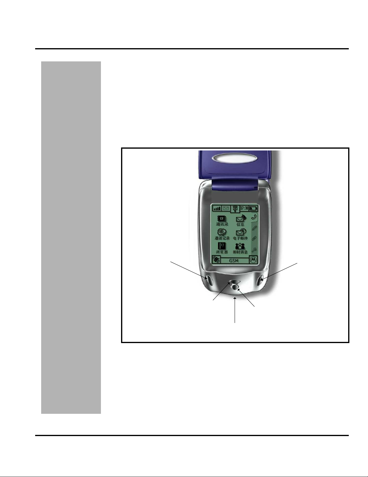
Controls, Indicators, and Input/Output (I/O) Connections
The A388c telephone’s controls are located on the front of the device
(see Figure 1). Controls on the front of the phone include a Power ON/OFF button,
Home Key, and a Up /Down key Soft Menu key on the left and right side. Indicators,
in the form of icons, are displayed on the LCD. Service status is indicated by a tricolor light emitting diode (LED) (not shown) located on top of the phone.
Additionally, I/O connectors consisting of a headset jack and an accessory port are
located on the top and bottom of the phone, respectively. See Figure 1.
UP /
SOFT MENU KEY
HOME KEY
POWER ON/OFF
CHARGER / DATA
PORT
Figure 1. A388c Telephone Controls, Indicators, and I/O
DOWN /
SOFT MENU KEY
020035-o
DRAFT
6809462A54 March 21, 2003 13
Page 14

General Operation Product Family 0C81
Menu Navigation
A388c telephones are equipped with a new user-friendly interface that employs 4
main menus. See Figure 2. Select each menu by tapping its tab on the right hand
side of the screen. Each menu contains up to six function icons that make up a
function group.
The tab represents the Communications Group.
The tab represents the Tools Group.
The tab represents the Setup Group.
The Setup Group allows you to configure and personalize the phone, as well as
providing the capability to connect the phone to other devices.
011660-o
Figure 2. A388c Menu Navigation
Liquid Crystal Display (LCD)
The color LCD provides a 65K TFT color touchscreen display. The display measures
240 x320 pixels.
The LCD screen displays the main menu icons and all of the function group icons.
You can navigate around the touch screen using the stylus to select the desired
functions.
Display animation makes the phone’s menus move smoothly as the user scrolls up
and down.
➧
Whether a phone displays all indicators depends on the programming and services
to which the user subscribes.
DRAFT
14 March 21, 2003 6809462A54
Page 15

Level 1 and 2 Service Manual General Operation
Figure 3 shows some common icons displayed on the LCD.
Figure 3. A388c Icon Indicators
Table 1. Icon Indicators and Description
Icon Description
Signal Strength Indicator. Shows the strength of the phone’s connection with the
network.
Antenna Off Indicator. Calls cannot be sent or received when the “antenna off”
indicator is displayed. The device is in PDA mode.
0
12:26
In Use Indicator. Appears when a call is in progress.
Roam Indicator. Appears when the phone uses another network system outside
the user’s home network. When leaving the home network area, the phone roams,
or seeks, another network.
GPRS Indicator. Appears when the phone is in GPRS mode.
Message Waiting Indicator. Appears when the phone receives a text message or
voice message. This is a network-dependent feature.
Battery Level Indicator. Shows the amount of charge left in the battery. The more
segments visible, the greater the charge. Recharge the battery as soon as possible
when the Low Battery warning message appears.
Invalid Battery Indicator.
Clock. Shows the current time. This is a network-dependent feature.
Alert Setting Indicator. Shows the current selected alert. The default alert setting
is a ringer.
DRAFT
6809462A54 March 21, 2003 15
Page 16

General Operation Product Family 0C81
Alert Settings
A388c telephones include up to 32 preset alert tones and vibrations that can be
applied to all alert events at the same time.
Battery Function
G
➧
➧
Pressing either volume key will mute the alert.
Battery Gauge
The telephone displays a battery level indicator icon in the idle screen to indicate
the battery charge level. The gauge shows four levels: 100%, 66%, 33%, and Low
Battery.
Battery Removal
Removing the battery causes the device to immediately shut down and any pending
work (for example, partially entered phone book entries or outgoing messages) is
lost.
To ensure proper memory retention, turn OFF the phone before removing the
battery. Immediately replace the old battery with a fresh battery.
If the battery is removed while receiving a message, the message will be lost.
Operation
For detailed operating instructions, refer to the appropriate User Guide listed in
the Related Publications section toward the end of this manual.
DRAFT
16 March 21, 2003 6809462A54
Page 17

1 and 2
Level 1 and 2 Service Manual Tools and Test Equipment
6809462A54
0C81
Tools and Test Equipment
The following table lists tools and test equipment recommended for disassembly
and reassembly of A388c telephones. Use either the listed items or equivalent.
Table 2. General Test Equipment and Tools
Motorola Part Number
RSX4043-A Torque Driver Used to remove and replace screws
1
Description Application
—
See Table 6 Charger
0180386A82
6680388B67
6680388B01 Tweezers, plastic Used during assembly/disassembly
2
—
3
—
8102430Z04 GSM / DCS Test SIM Card Used to enable manual test mode
1. To order in North America, contact Motorola Aftermarket and Accessories Division (AAD) at (847) 538-8000;
Internationally, AAD can be reached by calling +1 847 5388023 or faxing +1 847 5763023.
2. Not available from Motorola. To order, contact Plato Products, Inc. at (626) 965-8044.
3. Not available from Motorola. To order, contact Hewlett Packard at (800) 452-4844.
Torque Driver Bit T-6 Plus, Apex 440-6IP
Torx Plus or equivalent
Antistatic Mat Kit (includes 66-80387A95
antistatic mat, 66-80334B36 ground
cord, and 42-80385A59 wrist band)
Disassembly tool, plastic with flat and
pointed ends
Tweezers, stainless steel, Type 2
pointed blade, Plato part number
TZF-401-2 or equivalent
Digital Multimeter, HP34401A Used to measure battery voltage
Used with torque driver
Used to charge battery and to power
device
Provides protection from damage to
device caused by electrostatic discharge
(ESD)
Used during assembly/disassembly of
device
Used for flip removal.
DRAFT
6809462A54 March 21, 2003 17
Page 18

Disassembly Product Family 0C81
Disassembly
The procedures in this section provide instructions for the disassembly of a A388c
telephone. Tools and equipment used for the phone are listed in Table 2, preceding.
Many of the integrated devices used in this equipment are vulnerable to damage
G
G
Removing and Replacing the Stylus
from electrostatic discharge (ESD). Ensure adequate static protection is in place
when handling, shipping, and servicing the internal components of this equipment.
Avoid stressing the plastic in any way to avoid damage to either the plastic or
internal components.
1. Grasp the stylus and pull straight out of the bottom of the telephone as shown
in Figure 4.
Figure 4. Removing the stylus
2. To replace, insert the stylus, pointed end first, into the styles holder on the
bottom of the telephone. Push until fully seated in the holder.
Removing and Replacing the Battery
All batteries can cause property damage and/or bodily injury such as burns if a
conductive material such as jewelry, keys, or beaded chains touch exposed terminals.
E
The conductive material may complete an electrical circuit (short circuit) and
become quite hot. Exercise care in handling any charged battery, particularly when
placing it inside a pocket, purse, or other container with metal objects.
1. Ensure the phone is turned off.
2. Slide the battery latch in the direction of the arrow as shown in Figure 5-1.
DRAFT
STYLUS
011638-o
18 March 21, 2003 6809462A54
Page 19

Level 1 and 2 Service Manual Disassembly
3. While holding the battery latch open, lift the end of the battery and remove it
completely. See Figures 5-2 and 5-3.
BATTERY
1
BATTERY
LATCH
2
3
BATTERY
CONTACTS
BATTERY
COMPARTMENT
011639-o
Figure 5. Removing the battery
There is a danger of explosion if the Lithium Ion battery is replaced incorrectly.
Replace only with the same type of battery or equivalent as recommended by the
E
DRAFT
battery manufacturer. Dispose of used batteries according to the manufacturer’s
instructions.
4. To replace, align the battery with the battery compartment so the contacts on
the battery match the battery contacts in the phone.
5. Insert the tabs at the base of the battery into the slots at the bottom of the
battery compartment.
6. Push the top of the battery down until it snaps into place.
6809462A54 March 21, 2003 19
Page 20

Disassembly Product Family 0C81
Removing and Replacing the Subscriber Identity Module (SIM)
1. Remove the battery as described in the procedures.
2. Slide the SIM holder in the direction of the arrow (Figure 6-1) to unlock and
rotate (Figure 6-2) to open.
3. Carefully slide the SIM from its holder as shown in Figure 6-3.
4. To replace, insert the SIM into the holder, ensuring the keyed corner of the
SIM aligns with the notch molded into the holder.
BATTERY
COMPARTMENT
1
SIM HOLDER
SIM
2
SIM CONTACTS
3
011640-o
Figure 6. Removing the SIM
5. Close the SIM holder and slide to lock.
DRAFT
20 March 21, 2003 6809462A54
6. Replace the battery as described in the procedures.
Page 21

Level 1 and 2 Service Manual Disassembly
Removing and Replacing the Antenna
1. Remove the battery as described in the procedures.
2. By hand, rotate the antenna counterclockwise until loose as shown in
Figure 7-1.
2
1
Figure 7. Removing the antenna
3. When the antenna threads are completely disengaged, pull the antenna
straight out of the phone housing to remove. Figure 7-2.
Ensure antenna threads are properly engaged before tightening to prevent damage
G
Removing and Replacing the Rear Housing
G
to the antenna or housing.
4. To replace, insert the threaded end of the antenna carefully into the housing
and, after ensuring the threads are properly engaged, rotate clockwise. Tighten
firmly by hand.
5. Replace the battery as described in the procedures.
This product contains static-sensitive devices. Use anti-static handling procedures
to prevent electrostatic discharge (ESD) and component damage.
1. Remove the battery, SIM, and antenna as described in the procedures.
011641-o
In addition to 4 screws, the rear housing is fastened with 4 plastic catches. The
G
DRAFT
6809462A54 March 21, 2003 21
catches are fragile and should be handled with care.
Page 22

Disassembly Product Family 0C81
2. Using the flat end of the disassembly tool, remove the 2 housing screw plugs
(Figure 22, “Exploded view diagram,” on page 41, Item 21).
3. Using a Torx driver with a T-6 bit, remove the 4 screws from the rear housing.
See Figure 8A.
4. With the flat end of the disassembly tool, carefully press the 4 housing catches
inward to release the rear housing. See Figure 8B.
SCREW, T-6,
4 PLACES
A
HOUSING CATCH,
4 PLACES
B
REAR HOUSING
C
FRONT HOUSING
011642-o
Figure 8. Removing the rear housing
5. Lift the rear housing away from the front housing as shown in Figure 8C.
6. To replace, align the housing catches then press the rear housing down until
the 4 housing catches engage. Press the housings together until the catches
snap into place.
DRAFT
7. Replace the 4 screws and tighten securely. Do not over tighten.
22 March 21, 2003 6809462A54
Page 23

Level 1 and 2 Service Manual Disassembly
8. Replace both housing screw plugs.
9. Replace the antenna, SIM, and battery as described in the procedures.
Removing and Replacing the Real Time Clock (RTC) Battery
1. Remove the battery, SIM, antenna, and rear housing as described in the
procedures
DISASSEMBLY TOOL
.
MAIN BOARD
BATTERY HOLDER
RTC BATTERY
+ UP
011643-o
Figure 9. Removing the RTC battery
2. Using the flat end of the disassembly tool, gently pry the RTC battery from its
socket on the display board. See Figure 9.
Use only non-conductive tools, such as the plastic disassembly tool and the plastic
G
DRAFT
tweezer, when removing and replacing the RTC battery.
3. To replace, insert the new RTC battery into its socket on the main board. The
plastic tweezer may be used to replace the RTC battery. Be sure the positive
battery terminal is up (facing away from the board) and the battery is
completely seated in its socket.
4. Replace the rear housing, antenna, SIM, and battery as described in the
procedures.
6809462A54 March 21, 2003 23
Page 24

Disassembly Product Family 0C81
Removing and Replacing the Alert Gasket
1. Remove the battery, SIM, antenna, and rear housing as described in the
procedures.
2. Using the plastic tweezers, grasp the alert gasket and pull completely out of
the housing as shown in Figure 10.
ALERT GASKET
REAR HOUSING
Figure 10. Removing the alert gasket
3. To replace, insert the alert gasket into the rear housing and press until fully
seated. Be sure the openings in the gasket and the housing align with each
other.
4. Replace the rear housing, antenna, SIM, and battery as described in the
procedures.
PLASTIC
TWEEZERS
011644-o
DRAFT
24 March 21, 2003 6809462A54
Page 25

Level 1 and 2 Service Manual Disassembly
Removing and Replacing the Light Guide
1. Remove the battery, SIM, antenna, and rear housing as described in the
procedures.
2. Using the pointed end of the disassembly tool from inside the rear housing,
firmly push the light guide straight out of the housing as shown in
Figure 11-1, then remove completely (Figure 11-2).
DISASSEMBLY TOOL
REAR HOUSING
LIGHT GUIDE
1
2
LIGHT GUIDE
011645-o
Figure 11. Removing the light guide
3. To replace, insert the light guide straight into the opening in the top of the rear
housing and push until fully seated.
4. Replace the rear housing, antenna, SIM, and battery as described in the
procedures.
DRAFT
6809462A54 March 21, 2003 25
Page 26

Disassembly Product Family 0C81
Removing and Replacing the Battery Latch
1. Remove the battery, SIM, antenna, and rear housing as described in the
procedures.
2. Using the disassembly tool inside the rear housing, disengage both of the
battery latch catches as shown in Figure 12-1.
BATTERY
LATCH CATCH
1
1
2
Figure 12. Removing the battery latch
3. Slide the battery latch in the direction of the arrow shown in Figure 12-2 and
remove completely from the housing. Be careful not to lose the battery latch
spring during removal.
4. To replace, slip the battery latch spring over its post on the battery latch then
slide the latch and spring straight into the opening on the rear housing. Press
the latch until both catches lock into place inside the rear housing.
5. Replace the rear housing, antenna, SIM, and battery as described in the
procedures.
REAR HOUSING
BATTERY
LATCH
SPRING
BATTERY LATCH
011646-o
DRAFT
26 March 21, 2003 6809462A54
Page 27

Level 1 and 2 Service Manual Disassembly
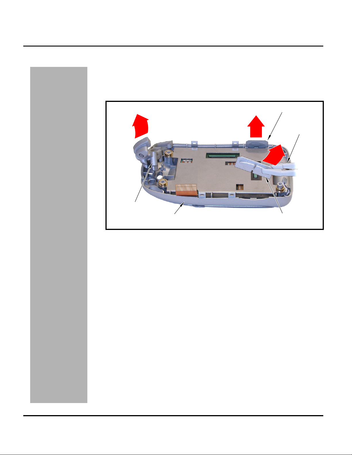
Removing and Replacing the Main Board
This product contains static-sensitive devices. Use anti-static handling procedures
G
G
to prevent electrostatic discharge (ESD) and component damage.
1. Remove the battery, SIM, antenna, and rear housing as described in the
procedures
The flexible printed cable (FPC or flex) is easily damaged. Exercise extreme care
when handling.
2. Using the flat end of the disassembly tool, slide both ends of the flex connector
latch away from the connector body to unlock the flex. See Figure 13-1.
3. Using the plastic tweezers, carefully disconnect the flex from the main board
as shown in Figure 14.
4. Disconnect the speaker leads from the speaker connector on the main board.
See Figure 13-2.
.
FLEX
CONNECTOR
CONNECTOR LATCH
MAIN BOARD
SPEAKER
CONNECTOR
2
11
SPEAKER LEADS
DISASSEMBLY TOOL
FLEX
DRAFT
Figure 13. Disconnecting the flex and speaker from the main board
6809462A54 March 21, 2003 27
011647-o
Page 28

Disassembly Product Family 0C81
PLASTIC
TWEEZERS
FLEX
MAIN BOARD
011648-o
Figure 14. Disconnecting the flex from the main board
5. Lift the transceiver board assembly completely from the front housing as
shown in Figure 15.
MAIN
BOARD
FRONT
HOUSING
011649-o
Figure 15. Removing the main board
6. To replace, insert the transceiver board assembly into the front housing with
the flex connector on top. Be sure the main board assembly is properly seated
on the 4 front housing posts.
Ensure the keys and buttons are correctly positioned in the front housing. Verify
➧
operation of the keys and buttons after reassembling the phone.
7. Insert the flex squarely into the flex connector on the transceiver board and,
after ensuring it is fully seated, close the connector latch to lock in place.
8. Reconnect the speaker leads.
DRAFT
28 March 21, 2003 6809462A54
Page 29

Level 1 and 2 Service Manual Disassembly
9. Replace the rear housing, antenna, SIM, and battery as described in the
procedures.
Removing and Replacing the Microphone
1. Remove the battery, SIM, antenna, rear housing, and main board as described
in the procedures
.
PLASTIC
TWEEZERS
Figure 16. Removing the microphone
2. Observe the orientation of the microphone before removing.
3. Using the plastic tweezers, carefully pull the microphone straight out of the
main board as shown in Figure 16.
MICROPHONE
MAIN BOARD
011650-o
The microphone connector pins are easily bent or broken. Exercise care when
➧
replacing the microphone.
4. To replace, insert the microphone connector pins into the main board socket
and press until the microphone is seated flat against the board. Be sure to
observe proper orientation when replacing the microphone.
DRAFT
6809462A54 March 21, 2003 29
5. Replace the main board, rear housing, antenna, SIM, and battery as described
in the procedures.
Page 30
Disassembly Product Family 0C81
Removing and Replacing the Keypad and Buttons
1. Remove the battery, SIM, antenna, rear housing, and main board as described
in the procedures
2. Using the plastic tweezers, lift the volume button, voice button, and keypad
from the front housing as shown in Figure 17.
.
VOICE BUTTON
PLASTIC
TWEEZERS
KEYPAD
FRONT HOUSING
Figure 17. Removing the external buttons
3. To replace, insert the keypad and buttons into the front housing. Make sure
they align properly with the openings in the front housing.
4. Replace the main board, rear housing, antenna, SIM, and battery as described
in the procedures.
5. After reassembly, operate all the keypad and buttons to verify correct function.
VOLUME BUTTONS
011651-o
DRAFT
30 March 21, 2003 6809462A54
Page 31

Level 1 and 2 Service Manual Disassembly
Removing and Replacing the Touch Screen Display Assembly
This product contains static-sensitive devices. Use anti-static handling procedures
G
to prevent electrostatic discharge (ESD) and component damage.
1. Remove the battery, SIM, antenna, rear housing, main board, external keys,
and buttons as described in the procedures
.
TOUCH SCREEN
DISPLAY ASSEMBLY
FRONT HOUSING
Figure 18. Removing the touch screen display assembly
2. Carefully lift the touch screen display assembly straight up and away from the
front housing as shown in Figure 18.
The touch screen display is fragile. Do not twist, pry, or drop the assembly during
G
DRAFT
6809462A54 March 21, 2003 31
removal and reassembly.
3. To replace, align the touch screen display assembly with the 4 posts inside the
front housing and set in place.
4. Replace the external keys, buttons, main board, rear housing, antenna, SIM,
and battery as described in the procedures.
POST, 4 PLACES
011652-o
Page 32

Disassembly Product Family 0C81
Removing and Replacing the Flip Assembly
1. Remove the battery, SIM, antenna, rear housing, main board, external keys,
G
buttons, and touch screen display assembly as described in the procedures
After releasing the hinge assembly in the following step, DO NOT attempt to
completely separate the flip assembly from the front housing until you have safely
routed the speaker leads through the opening in the front housing.
FLIP ASSEMBLY
POINTED TWEEZERS
.
1
FLIP ASSEMBLY SLOT
FRONT HOUSING
2
RIGHT HOUSING
KNUCKLE
3
4
Figure 19. Removing the flip assembly
HINGE ASSEMBLY
HOUSING SOCKET
HINGE POST
SPEAKER LEADS
011653-o
DRAFT
32 March 21, 2003 6809462A54
Page 33

Level 1 and 2 Service Manual Disassembly
2. Using the pointed tweezers through the flip housing slot, depress the hinge
assembly to release the flip assembly from the front housing knuckle.
See Figure 19-1.
3. Tilt and slightly separate the flip assembly (Figures 19-2 and 19-3) from the
front housing. Carefully pull the speaker leads through the front housing
opening, then completely separate the housings as shown in Figure 19-4.
4. The hinge assembly can be removed by pulling it straight out of the flip
assembly. See Figure 19-4.
5. To replace, insert the hinge assembly into the flip assembly.
6. While carefully routing the speaker leads through the opening in the front
housing, insert the front housing hinge post into the flip housing.
7. Using the flat end of the disassembly tool, depress the hinge assembly and slide
the end of the hinge into the socket molded into the right housing knuckle. The
hinge assembly will snap into place when it is properly aligned with the socket.
8. Replace the touch screen display assembly, external keys, buttons, main board,
rear housing, antenna, SIM, and battery as described in the procedures.
DRAFT
6809462A54 March 21, 2003 33
Page 34

SIM Cards and Identification Product Family 0C81
SIM Cards and Identification
SIM Card
A SIM card is required to access the existing local GSM network and remote
networks when traveling.
The SIM card contains:
• All the data necessary to access GSM services.
• The ability to store user information such as phone numbers.
• All information required by the network provider to provide access to the
network.
Personality Transfer
A personality transfer is required when a phone is Express Exchanged or when the
main board is replaced. Personality transfers reproduce the customer's original
personalized details such as menu and stored memory such as phone books, or even
just program a unit with basic user information such as language selection.
Identification
Personality transfers performed at levels 1 and 2 service centers include only the
➧
information stored on the SIM.
Each Motorola GSM device is labeled with a variety of identifying numbers. The
following information describes the current identifying labels.
Mechanical Serial Number (MSN)
The Mechanical Serial Number (MSN) is an individual unit identity number and
remains with the unit throughout the life of the unit.
The MSN can be used to log and track a unit on Motorola's Service Center Database.
The MSN is divided into 4 sections as shown in Figure 20.
MSN 10 Digits
3 Digits 1 Digit 2 Digits 4 Digits
APC DC DC SNR
Account Product Code
i.e. StarTAC Phone130
TM
Distribution Center
i.e. Easter Inch
Date Code: Year and
Month of Shipment
Unit's individual serial
number
000807a
Figure 20. MSN Label
DRAFT
34 March 21, 2003 6809462A54
Page 35

Level 1 and 2 Service Manual SIM Cards and Identification
International Mobile Station Equipment Identity (IMEI)
The International Mobile station Equipment Identity (IMEI) number is an
individual number unique to the PCB and is stored within the unit's memory. The
following diagram illustrates the various parts of this number.
IMEI 16 Digits
6 Digits 2 Digits 6 Digits 2 Digits
TAC FAC SNR IU
Type Approval Code Distribution Center
factory code
Figure 21. IMEI Label
Other label number configurations present are:
• TRANSCEIVER NUMBER: Identifies the product type. Normally the SWF
number. (for example, V100).
• PACKAGE NUMBER: Identifies the equipment type, mode, and language in
which the product is shipped.
Individual PCB Serial
Number
Internal Use - spare
digits
000808o
DRAFT
6809462A54 March 21, 2003 35
Page 36

Troubleshooting Product Family 0C81
Troubleshooting
Manual Test Mode
Motorola A388c telephones are equipped with a manual test mode capability. This
allows service personnel to verify functionality and perform fault isolation by
entering keypad commands.
To enter the manual test command mode, a GSM / DCS test SIM must be used.
1. Press , to turn the phone OFF.
2. Remove the battery as described in the procedures.
3. Remove the customer’s SIM card from the phone as described in the
procedures.
4. Insert the test SIM into the SIM slot.
5. Replace the battery as described in the procedures.
6. Press , to turn the phone ON.
Press and hold the # button for approximately 3 seconds until TEST displays on the
screen. The phone may now be issued test commands listed in Table 3.
Manual Test Mode Commands
Table 3. Test Commands
Test Command Test Function/Name
Press and hold # for 2 seconds Enter manual test mode
01# Exit manual test mode
07x# Mute RX audio path
08# Unmute RX audio path
09# Mute TX audio path
10# Unmute TX audio path
15x# Generate tone
1590# Vibrate Mode
1591# Ringer Mode
16# Mute tone generator
19# Display software version number of Call Processor
20# Display software version number of Modem
36# Initiate acoustic loopback
360# Full Rate
361# Enhanced Full Rate
362# Half Rate
37# Stop test
38# Activate Mini SIM
39# Deactivate Mini SIM
43x# Change audio path
47x# Set audio volume
51# Enable sidetone
DRAFT
36 March 21, 2003 6809462A54
Page 37

Level 1 and 2 Service Manual Troubleshooting
Table 3. Test Commands (Continued)
Test Command Test Function/Name
52# Disable sidetone
54# Show service indicator LED (0 - Off, 1 - Red, 2 - Green, 3 - Amber) (flip must be closed)
57# Initialize non-volatile memory
58# Display security code
58xxxxxx# Modify security code
59# Display lock code
59xxx# Modify lock code
60# Display IMEI
980# DCS Mode (PF B95 only)
981# GSM Mode (PF B95 only)
962# PCS Mode (PF C21 only)
99# Display all pixels
Troubleshooting Chart
Table 4. Product Family 0C45 Telephone: Level 1 and 2 Troubleshooting Chart
SYMPTOM PROBABLE CAUSE VERIFICATION AND REMEDY
1. Telephone will not turn on or stay on. a) Battery either discharged or
2. Telephone exhibits poor reception or
erratic operation such as calls frequently
dropping or weak or distorted audio.
3. Display is erratic, or provides partial or
no display.
defective.
b) Battery connectors open or
misaligned.
c) Main board assembly defective. Remove the main board assembly. Substitute a
a) Antenna assembly defective. Check to make sure that the antenna pin is
b) Main board assembly defective. Replace the main board assembly (refer to 1c).
a) Main board connections faulty. Remove rear housing from unit, check general
DRAFT
Measure battery voltage across a 50 ohm (>1
Watt) load. If the battery voltage is <3.25 Vdc,
recharge the battery using the appropriate
battery charger. If the battery will not recharge,
replace the battery. If battery is not at fault,
proceed to b.
Visually inspect the battery connectors on both
the battery and the telephone. Realign and, if
necessary, either replace the battery or refer to
a Level 3 Service Center for the battery
connector replacement. If battery connectors
are not at fault, proceed to c.
known good assembly and temporarily
reassemble the unit. Depress the PWR button; if
unit turns on and stays on, disconnect the dc
power source and reassemble the telephone
with the new main board assembly. Verify that
the fault has been cleared.
properly connected to the main board assembly.
If connected properly, substitute a known good
antenna. If the fault is still present, proceed to b.
Verify that the fault has been cleared and
reassemble the unit with the new main board
assembly.
condition of flexible printed cable (flex). If the flex
is good, check that the flex connector is properly
locked. If faulty connector, replace the main
board assembly. If connector is not at fault,
proceed to b.
6809462A54 March 21, 2003 37
Page 38

Troubleshooting Product Family 0C81
Table 4. Product Family 0C45 Telephone: Level 1 and 2 Troubleshooting Chart (Continued)
SYMPTOM PROBABLE CAUSE VERIFICATION AND REMEDY
4. Incoming call alert transducer audio
distorted or volume is too low.
5. Telephone transmit audio is weak.
(usually indicated by called parties
complaining of difficulty in hearing voice).
6. Receive audio from earpiece speaker is
weak or distorted.
7. Telephone will not recognize or accept
SIM card.
b) Touch screen display assembly
defective.
c) Main board assembly defective. Replace the main board assembly (refer to 1c).
Faulty alert transducer or main board
assembly.
a) Microphone connections to the
main board assembly defective.
b) Microphone defective. Gain access to microphone. Disconnect and
c) Main board assembly defective. Replace the main board assembly (refer to 1c).
a) Connections to or from main board
assembly defective.
b) Earpiece speaker defective. Replace the flip assembly as described in the
c) Antenna assembly defective. Check to make sure the antenna is installed
d) Main board assembly defective. Replace the main board assembly (refer to 1c).
a) SIM card defective. Check the SIM card contacts for dirt. Clean if
Remove the touch screen display assembly as
described in the procedures. Temporarily
reassemble unit with a known good touch
screen display assembly and verify proper
operation. If fault is cleared, reassemble unit
with the new assembly. If fault not cleared,
proceed to c.
Verify that the fault has been cleared and
reassemble the unit with the new main board
assembly.
Replace the main board assembly (refer to 1c).
Verify that the fault has been cleared and
reassemble the unit with the new main board
assembly.
Gain access to the microphone as described in
the procedures. Check connections. If connector
is faulty proceed to c; if the connector is not at
fault, proceed to b.
substitute a known good microphone. Place a
call and verify improvement in transmit signal as
heard by called party. If good, reassemble with
new microphone. If microphone is not at fault,
reinstall original microphone and proceed to c.
Verify that the fault has been cleared and
reassemble the unit with the new main board
assembly.
Gain access to the main board assembly as
described in the procedures. Check the speaker
leads and connector from the flip assembly to
the main board assembly. If speaker leads are at
fault, replace the flip assembly. If connector is at
fault, proceed to d. If connection is not at fault,
proceed to b.
procedures. Temporarily reassemble unit and
verify proper operation. If fault has not been
cleared, replace original flip assembly and
proceed to proceed to c.
correctly. If the antenna is installed correctly,
substitute a known good antenna assembly. If
this does not clear the fault, reinstall the original
antenna assembly and proceed to d.
Verify that the fault has been cleared and
reassemble with the new main board assembly.
necessary and check if fault has been cleared. If
the contacts are clean, insert a known good SIM
card into the telephone. Power up the unit and
confirm that the card has been accepted. If the
fault no longer exists, replace the defective SIM
card. If the SIM card is not at fault, proceed to b.
DRAFT
38 March 21, 2003 6809462A54
Page 39

Level 1 and 2 Service Manual Troubleshooting
Table 4. Product Family 0C45 Telephone: Level 1 and 2 Troubleshooting Chart (Continued)
SYMPTOM PROBABLE CAUSE VERIFICATION AND REMEDY
b) Connections between touch screen
display assembly and main board
assembly faulty.
c) Touch screen display assembly
defective.
d) Main board assembly defective. Replace the main board assembly (refer to 1c).
8. Phone does not sense when flip is
opened or closed (usually indicated by
inability to answer incoming calls by
opening the flip, or inability to make
outgoing calls).
9. Vibrator feature not functioning. Vibrator on main board defective. Replace the main board assembly (refer to 1c).
10. Internal Charger not working. Faulty charger circuit on main board
11. Real Time Clock resetting when
standard battery is removed.
12. No or weak audio when using headset. a) Headset not fully pushed home. Ensure the headset plug is fully seated in the
a) Magnet in flip assembly missing or
defective.
b) Sensor on main board defective. Replace the main board assembly (refer to 1c).
assembly.
Lithium Ion RTC battery on the main
board may be depleted.
b) Faulty jack socket on main board
assembly.
Refer to remedy 3a and 3b. If fault has not been
cleared, proceed to c.
Replace touch screen display assembly with a
known good one. Temporarily reassemble unit
and verify proper operation. If fault has not been
cleared, replace original touch screen display
assembly and proceed to d.
Verify that the fault has been cleared and
reassemble the unit with the new main board
assembly.
Replace flip assembly with known good one.
Refer to the procedures. Place call to phone and
verify ability to answer by opening flip. If fault is
cleared, rebuild phone with new flip assembly. If
fault is still present, replace original flip
assembly and proceed to b.
Verify that the fault has been cleared and
reassemble the unit with the new main board
assembly.
Verify that the fault has been cleared and
reassemble the unit with the new main board
assembly.
Test a selection of batteries in the rear pocket of
the desktop charger. Check LED display for the
charging indications. If these are charging
properly, then the internal charger is at fault.
Replace the main board assembly (refer to 1c).
Verify that the fault has been cleared and
reassemble the unit with the new main board
assembly.
Replace the RTC battery as described in the
procedures. Check RTC time does not reset.
jack socket.
Replace the main board assembly (refer to 1c).
Verify that the fault has been cleared and
reassemble the unit with the new main board
assembly.
DRAFT
6809462A54 March 21, 2003 39
Page 40

Troubleshooting Product Family 0C81
Programming: Software Upgrade and Flexing
Contact your local technical support engineer for information about equipment and
procedures for flashing and flexing.
Part Number Charts
The following charts are provided as a reference for the parts associated with
A388c telephones.
Related Publications
Motorola 388 Wireless Phone User Guide, Simple Chinese 9804586R01
Motorola 388 Wireless Phone User Guide, Traditional Chinese 9804586R02
Motorola 388 Wireless Phone User Guide, English 9804586R03
DRAFT
40 March 21, 2003 6809462A54
Page 41

Level 1 and 2 Service Manual Troubleshooting
Exploded View Diagram
1
2
3
4
5
6
7
8
9
11
12
13
14
15
16
17
18
19
20
10
Figure 22. Exploded view diagram
21
011654-o
DRAFT
6809462A54 March 21, 2003 41
Page 42

Troubleshooting Product Family 0C81
Exploded View Parts List
Table 5. Exploded View Parts List
Item
Number
1 See Table 5 See Table 5 Flip assembly
2 0164059E01 0164057E01 Front housing assembly
3 5009135L07 5009135L07 Microphone
4 See Table 5 CHLF4336AA Main board
5 3804504R01 3804504R01 Button, volume
6 6003710K08 6003710K09 Battery, RTC
7 3804506R01 3804506R02 Keypad
8 See Table 5 See Table 5 Rear housing assembly
9 0164055E01 0164055E01 Stylus assembly
10 0364579E01 0364579E01 Screw, housing (4)
11 5504555R01 5504555R01 Hinge assembly
12 0164056E01 0164056E01 Touch screen display assembly
13 0504488R01 0504488R01 Gasket, alert
14 6104512R01 6104512R01 Light guide
15 3804505R01 3804505R01 Button, record
16 0164054E01 0164054E02 Antenna assembly
17 4104584R01 4104584R01 Spring, battery latch
18 5504515R01 5504515R01 Latch, battery
19 See Table 5 See Table 5 Battery, Lithium Ion
20 0504489R01 0504489R01 Plug, RF
21 0504487R01 0504487R01 Plug, housing screw (2)
Note: 1. Not available as spares in EMEA Service markets.
Motorola
Part Number
(EMEA)
Motorola
Part Number
(North America &
Latin America)
Description
1
There is a danger of explosion if the Lithium Ion battery is replaced incorrectly. Replace only with
E
the same type of battery or equivalent as recommended by the battery manufacturer. Dispose of
used batteries according to the manufacturer’s instructions.
DRAFT
42 March 21, 2003 6809462A54
Page 43

Level 1 and 2 Service Manual Troubleshooting
Model-dependent Part Numbers
Table 6. Model-dependent Part Numbers
Model
Item
Number
1 Flip assembly 0164060E01 0164060E02 0164060E02 0164060E02 0164060E02 0164060E02
4 Main board
8 Rear housing assembly 0164058E01 0164058E02 0164058E02 0164058E02 0164058E02 0164058E02
19
Note: 1. Not available as spares in EMEA Service markets.
Part Description
1
Battery, Lithium Ion, 800
mAh
SA04090A
Nickel
CHLF4290AA CHLF4290AA CHLF4290AB CHLF4290AB CHLF4290AC CHLF4290AC
SNN5715 SNN5709 SNN5714 SNN5708 SNN5714 SNN5709
SA04091A
Onyx Blue
SA0499A
Nickel
SA0500A
Onyx Blue
92570XYESA
388
Nickel
Onyx Blue
Accessories
Table 7. Accessories
Part Description Part Number
Travel Charger, PRC
Travel Charger, UK
Travel Charger, US
Pouch CHYN4292
Headset, earbud, with send/end key SYN8419
TrueSync Kit CHYN4291
SPN4654
SPN4659
SPN4604
DRAFT
6809462A54 March 21, 2003 43
Page 44

Troubleshooting Product Family 0C81
DRAFT
44 March 21, 2003 6809462A54
Page 45

1 and 2
Index
Level 1 and 2 Service Manual Index
0C81
6809462A54
A
alert settings 14
antenna, removing and replacing
19
B
battery
function
gauge
removing
replacing
14
14
16
18
C
call forwarding 10
caller ID
Canadian Interference-Causing Equipment regulations
changes
commands, manual test mode
controls
conventions
copyrights
10
product
3
11
5
computer software
34
4
D
disassembly 16
E
exploded view diagram 39
exploded view parts list
40
F
FCC rules 3
features
flip assembly, removing and replacing
8
call forwarding
voice recognition
Wireless Access Protocol (WAP)
10
9
9
30
I
identification 32
international mobile station equipment identity
mechanical serial number
product
IMEI
33
Introduction
3
3
32
33
DRAFT
K
keypad, removing and replacing 28
L
light guide, removing and replacing 22, 23, 24
liquid crystal display (LCD)
12
M
manual test mode 34
microphone, removing and replacing
MSN
32
N
names
3
product
3
O
overview 8
P
part numbers
accessories
parts
38
exploded view diagram
exploded view parts list
product
changes
identification
names
publications, related
41
39
40
3
3
3
38
R
rear housing
removing
regulatory agency compliance
related publications
removing
antenna
battery
flip assembly
keypad
light guide
microphone
rear housing
SIM card
replacement parts
ordering
19
3
38
19
14, 16
30
28
22, 23, 24
27
19
18
6
27
6809462A54 March 21, 2003 Index-1
Page 46

Level 1 and 2 Service Manual Index
replacing
antenna
battery
flip assembly
keypad
light guide
microphone
revisions
service manual
19
16
30
28
22, 23, 24
27
5
S
serial number
mechanical
service manual
about
revisions
scope
service policy
customer support
out of box failure
product support
replacement parts
shut down
upon battery removal
SIM card
personality transfer
removing
replacing
specifications
support
customer
product
32
4
5
4
5
6
5
5
6
14
32
32
18
18
7
6
5
T
tools and test equipment 15
troubleshooting
manual test mode
manual test mode commands
34
34
34
U
user interface diagrams 14
V
voice recognition 9
W
warranty service 5
wireless access protocol (WAP)
6809462A54 March 21, 2003 Index-2
DRAFT
9
Page 47

Page 48

MOTOROLA, the Stylized M Logo, and all other trademarks indicated as such herein are trademarks of Motorola, Inc.
TrueSync is a trademark of Starfish, Inc., a wholly owned independent subsidiary of Motorola, Inc.
All other product or service names are the property of their respective owners.
® Reg. U.S. Pat. & Tm. Off.
2003 Motorola, Inc.
All rights reserved.
Personal Communications Sector,
Sawgrass International Concourse
789 International Parkway, Room S2C
Sunrise, Florida 33323
@6809462A54@
6809462A54-O
Page 49

../graphics/Motlogoshadow.eps 1
../graphics/M388_manual_cover.eps 1
../graphics/020035-a.eps 10
../graphics/011660-o.eps 11
../graphics/display_icons.eps 12
../graphics/011638-o.eps 15
../graphics/011639-o.eps 16
../graphics/011640-o.eps 17
../graphics/011641-o.eps 18
../graphics/011642-o.eps 19
../graphics/011643-o.eps 20
../graphics/011644-o.eps 21
../graphics/011645-o.eps 22
../graphics/011646-o.eps 23
../graphics/011647-o.eps 24
../graphics/011648-o.eps 25
../graphics/011649-o.eps 25
../graphics/011650-o.eps 26
../graphics/011651-o.eps 27
../graphics/011652-o.eps 28
../graphics/011653-o.eps 29
../graphics/000807-A.eps 31
../graphics/000808-o.eps 32
../graphics/011654-o.eps 38
 Loading...