

Page 1
Radio
Adapter (RBA)
for the Professional Radio Series
Model HHLN4125
6880309K16-O
Accessories
Page 2

and MOTOROLA are registered trademarks of Motorola, Inc.
The BLUETOO TH tra demarks are o wned by Telefonaktiebolaget LM Ericsson,
Sweden, and licensed to Motorola, Inc.
Page 3

TABLE OF CONTENTS
Safety and General Information. . . . . . . . . . . . . . . . .3
Electromagnetic Interference/Compatibility
Facilities. . . . . . . . . . . . . . . . . . . . . . . . . . . . . . . . .4
Aircraft. . . . . . . . . . . . . . . . . . . . . . . . . . . . . . . . . .4
Medical Devices. . . . . . . . . . . . . . . . . . . . . . . . . . .4
Safety and General
Use While Driving . . . . . . . . . . . . . . . . . . . . . . . . .9
Bluetooth Wireless Technology Overview . . . . . . . . .6
Getting Started
Installing the Radio Bluetooth Adapter (RBA) . . . . 8
Removing the Radio Bluetooth Adapter (RBA) . . . 9
Turning ON the RBA. . . . . . . . . . . . . . . . . . . . . . . .9
Establishing the Bluetooth Wireless
Connection. . . . . . . . . . . . . . . . . . . . . . . . . . . . .9
Connection Verification . . . . . . . . . . . . . . . . . . . .10
Lost Link . . . . . . . . . . . . . . . . . . . . . . . . . . . . . . .11
Turning OFF the RBA . . . . . . . . . . . . . . . . . . . . . .11
Disconnecting the Bluetooth Wireless
Connection. . . . . . . . . . . . . . . . . . . . . . . . . . . .12
LED Indicators. . . . . . . . . . . . . . . . . . . . . . . . . . .13
Operation
Operational Range . . . . . . . . . . . . . . . . . . . . . . . .14
Receiving. . . . . . . . . . . . . . . . . . . . . . . . . . . . . . .14
Transmitting. . . . . . . . . . . . . . . . . . . . . . . . . . . . .14
Volume Control . . . . . . . . . . . . . . . . . . . . . . . . . .15
VOX (Voice Activated Transmission) . . . . . . . . . .15
1
Page 4

Battery
Low Battery Alert. . . . . . . . . . . . . . . . . . . . . . . . .16
Battery Life . . . . . . . . . . . . . . . . . . . . . . . . . . . . . 16
Temperature Effects On Your RBA . . . . . . . . . . . . . .16
RBA Replacement Parts Lists . . . . . . . . . . . . . . . . .17
Service and Support . . . . . . . . . . . . . . . . . . . . . . . . .17
Warranty . . . . . . . . . . . . . . . . . . . . . . . . . . . . . . . . . .17
Replacing the HHLN4125 Side Connector Board. . . 18
2
Page 5

SAFETY AND GENERAL INFORMATION
IMPORTANT INFORMATION ON SAFE AND
EFFICIENT OPERATION.
READ THIS INFORMA T ION BEFORE USING
YOUR RADIO.
Users are not per m i tted to m a ke changes or
modify the device in any way. Change s or modifications not expressly approved by the party
responsible for complian ce could void the user’s
authority to operate the device. See 47 CFR Sec.
15.21.
This device complies with P art 15 of the U.S.
FCC Rules. Operation is subject to the following
two conditions:
(1) This device may not cause harmful interference, and (2) this device must accept any inte rference received, including interference that m ay
cause undesired operation. See 47 CFR Sec.
15.19(3).
3
Page 6

ELECTROMAGNETIC INTERFERENCE/
COMPATIBILITY
OTE: Nearly every electronic device is sus-
ceptible to electromagnetic interference
(EMI) if inadequately shielded, designed
or otherwise configured for electromagnetic compatibility.
Facilities
To avoid electromagnetic interference and/or
compatibility conflicts, turn off your device in any
facility where posted notices instruct you to do so.
Hospitals or health car e facilities m ay be using
equipment that is sensitive to external RF ene rgy.
Aircraft
When instructed to do so, turn off your device
when on board an aircraft. Any use of your device
must be in accordance w ith applicable regulations per airline crew instructions.
Medical Devices
Pacemakers
The Health Industry Manufacturers Association
recommends that a m ini mum se paration of 6
inches (15 centimeters) be maintained between a
4
Page 7

wireless device and a pacemaker. These recommendations are consist ent with the independent
research by, and recommend at ions of, Wireless
Techno lo gy Resea rc h.
Persons with pacemakers should:
• ALWAYS keep the wireless device more
than 6 inches (15 centim et er s) from their
pacemaker when the device is tur ned ON.
• not carry the device in th e br east pocket.
• use the ear opposite the pacemaker to min-
imize the potential for interference.
• turn the device OFF immediately if you
have any reason to suspect that interference is taking place.
Hearing Aids
Some digital wireless radio s m ay interfere with
some hearing aids. In th e event of such interference, you may want to consult your hearing aid
manufacturer to discuss alternatives.
Other Medical Devices
If you use any other personal medi cal device,
consult the manufacturer of your device to determine if it is adequately shielded from RF energy.
Your physician may be able to assist you in
obtaining this information.
5
Page 8

BLUETOOTH WIRELESS TECHNOLOGY OVERVIEW
At Motorola we believe that easy portable communication is the key to creating a safer environment. That’s why we designed this exciting new
two-way communication device called the Rad io
Bluetooth Adapter (RBA). The R BA re pr es ent s
another breakthroug h i n applying Bluetooth wireless technology by Motorola. This adapter allows
your ra dio to send and receive audio from a wireless accessory such as a Remote Speaker Microphone (RSM) without wire s.
This RBA uses a new protocol based on st at e-ofthe-art Bluetooth technology specificatio ns,
which result in simplifying the use of your radio.
Bluetooth wireless techno l ogy is an open standard, connecting wirel ess devices within a short
range. The range for this particular adapter
(RBA) and the Bluetooth audio accessory is
approximately 30 feet in ideal line-of-sight conditions. It is important to be aware that the specific
Bluetooth technology was designe d and e ng ineered f or use between your radio and special
Bluetooth audio accessories. Your Bluetooth
audio accessor y will not operate with other nonMotorola two-way radio Bluetooth pr oducts.
6
Page 9
If your radio is VO X (voice activated transmission)
capable, the Bluetooth wireless functionality will
continue with your adapter and a VOX capable
Bluetooth wireless headset.
We’re confident that once you try the Bl uetooth
wireless adapter and accessories , you’ll wonder
how you survived with all those attachment wires
in the first place!
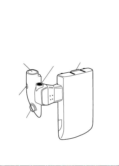
PTT
(Push-To-Talk)
LED
Indicator
Screw
BLUE Button
Latch
Figure 1. Radio Bluetooth Adapter
7
Page 10

GETTING STARTED
Installing the Radio Bluetooth Adapter (RBA)
OTE: The RBA is designed to clip onto the back
of specially designed radio batteries.
1. Place the bottom of the RBA to the battery.
Press the top latch of the RBA to the battery
until it snaps into place. Refer to Figure 2.
2. Attach the side connector to the radio’s
accessory connector. Secure the side connector with the metal scr ew using a coin or
thin bladed screwdriver.
Latch
Side
Connector
Metal
Screw
Figure 2. RBA and Radio Attachment
8
Page 11

Removing the Radio Bluetooth Adapter (RBA)
1. Detach the side connector from the acce ssory connec tor with the metal screw using a
coin or thin bladed screwdriver.
2. Detach the top latch by pressing down and
pulling the RBA away from the battery.
Turning ON the RBA
The RBA turns ON when the radio is turned ON.
The RBA LED lights GREEN for one second,
indicating success fu l power-up. When you first
turn on your RBA, it will first attempt to establish
a connection with the las t Bluetooth audio accessory it was connected to, otherwise it will attempt
to connect t o a new acces s ory.
Establishing the Bluetooth Wireless Connection
Following these simple steps establishes a new
connection when your RBA and audio accessory
are first turned on:
1. Turn ON your radio. The RBA turns on when
the radio is turned on.
• The RBA LED lights GREEN for one sec-
ond, indicating successful power-up.
2. Turn ON the Bluetooth wireless capable
audio accessor y. (Refer to your accessory
manual.)
9
Page 12

3. Place the audio accessory next to the radio.
(For best re sults ke ep both wi thin a f e w i nches
of each other.)
• The RBA LED flashes ORANGE until a
successful connection is established. If a
connection has not been established, the
LED flashes RED.
• Once the RBA and audio accessory have
connected, the RBA LED f lashes GREEN
every few seconds.
OTE: Connecting for the first time takes longer
to establish than subsequent connections.
Connection Verification
You may want to verify the wireles s connection
before you start communi cati ng with the accessory.
OTE: Pressing the audio accessory PTT but-
ton first, keys-up the radio
1. Press and hold the RBA BLUE button.
2. Press the audio acces sory PTT button.
• The RBA LED lights a solid GREEN for the
duration of the audio accessory PTT press.
If this does not happen, the connection was
not established and the connection process
will have to be repeated.
10
Page 13

Lost Link
If the connection is lost at any time, the RBA LED
flashes ORANGE until the connection is re-established. If a connect ion has not be en re- estab li shed
within 30 seconds t he LED flashes RED.
OTE: During the attempt to re-establish a con-
nection, your radio and PTT button function normally.
Turning OFF the RBA
If a wireless connectio n is est ablish ed, you can
turn off your RBA without losing its memory to the
connection with the au dio accessory. The connection is automatical l y re -e st ablishe d t he next
time the RBA is turned on.
1. To turn OFF the RBA, turn off the radio.
2. To turn ON the RBA, turn on the radio.
11
Page 14

Disconnecting the Bluetooth Wireless Connection
You can disconnect and re-establish the connection when bot h t he R BA an d au d io acce s so ry are
still on.
1. Press both the RBA BLUE and PTT buttons.
• The RBA LED flashes RED, indicating the
connection is broken.
2. To re-establish the connection while the RBA
and audio accesory are on, place the RBA
within a few inches of the audio accessory.
Press both the RBA’s BLUE and PTT buttons, then immediately p res s both the audio
accessory’s BLUE and PTT buttons.
12
Page 15

LED Indicators
RBA LED
Indicator Description
GREEN Solid GREEN for 1 second, indicates suc-
Flashing
GREEN
Flashing
ORANGE
RED Solid RED for 1 second followed by fl ashing
Flashing
RED
cessful RB A power-up, or...
Solid GREEN for 1 second, indicates suc-
cessful connection with an accessory, or...
Solid GREEN for duration of the PTT press
or while receiving, indicates the RBA is
functioning correctly.
Flashes GREEN every few seconds when
connected to the radio and no communication or transmission is taking place.
Flashes ORANGE every few seconds, indicates the RBA is attempting to reconnect or
reconnect
orange, indicates that connection is lost and
is attempting to reconnect to the accessory,
or...
Flashes RED every few seconds, indicates
connection is disconnected and has not
been re-established within 30 seconds.
to the accessory.
13
Page 16

OPERATION
Operational Range
For optimum performance from your RBA, use it
within 30 feet of your audio accessory . This range
will vary depending on environmental conditions,
i.e. clothing, radio placement on body, buildings.
Receiving
Once the RBA is connec te d to your aud io accessory, the radio speaker mutes and the audio is
heard only from the audio accessory.
• While receiving, the RBA LED lights a solid
GREEN for the duration of the received
communication.
Transmitting
The Push-To-Talk (PTT) button o n either the audio
accessory or the RBA in i t iates transmission.
OTES: Pressing the audio accessory or RBA
PTT button activates only the microphone in the audio accessory.
Pressing the radio’s PTT button activates only the microphone in the radio.
• While transmitting, the RBA LED lights a
solid GREEN for the duration of the trans mission.
14
Page 17

Volume Control
Refer to your Bluetooth wireless audio accessory
manual for any volume control instructi ons.
VOX (Voice Activated Transmission)
(Available only with select VOX capable radios)
If your radio is VOX capable and has been programmed into the radio, this feature can be
enabled to operate with the RBA and an audio
accessory.
OTE: VOX can only be enabled on the RBA
To Activate VOX
1. Turn off your radio.
2. Press and hold the RBA PTT button wh ile
3. Turn on your audio accessory.
4. Turn your radio to the assigned VOX channel.
5. Establish the wireless conn ection. Refer to
during radio power up.
turning on the radio. Release the PTT button
after power-up.
“Establishing the Bluetooth Wireless Connection” on page 9.
• Once the connection has been established,
your radio and audio accessory operate in
VOX m ode.
15
Page 18

To De-activate VOX
Press either the RBA or a udio a cces sory PTT b utt on.
• The radio exits VOX mo de and returns to
normal operation.
BATTTERY
Your RBA and batt ery are safe to charge in your
current rad io’s battery charger.
Low Battery Alert
Refer to your radio’s operator manual for specific
battery instructions.
Battery Life
Refer to your radio’s operator manual for specific
battery instructions.
TEMPERATURE EFFECTS ON YOUR RBA
Your RBA was desi g ned to work in all env ironments your current radio is designed for. Refer to
your radio’s manual for specific details.
16
Page 19

RBA REPLACEMENT PARTS LISTS
Parts List for HHLN4125
Side Connector Screw 0380475E01
Replacement Part
Side Connector Assembly 0185724M01
Radio Battery (for use with HHLN4125) HNN9003
RBA Replacement Parts Instruction Sheet 6880309K91
Motorola
Part Number
SERVICE AND SUPPORT
Your RBA is not repairable. If there is a problem
with the unit after the warranty period, please
order a replacement unit or replacement parts. T o
order replacement parts or for warranty information, contact Motorola Americas Accessories
Aftermarket Division (AAD) at:
1-800-422-4210 or 847- 538-8023.
WARRANTY
The RBA is covered under the standard Motorola
one (1) year lim ited warranty:
Refer to your Motorola dealer for detailed information on your RBA’s standard warranty.
17
Page 20

REPLACING THE HHLN4125 SIDE CONNECTOR
BOARD
Disassembl i ng t he RBA before the one (1) year
limited warranty has expired will void the warranty.
Disassembling the Side Connector Board
1. Detach the RBA from t he rad io.
2. Remove the two screws in
the housing/button assem bly using a T6 Torx® driver.
3. Gently pull the rubber gasket from the housing/button
assembly.
4. Lift the cover flap of the
15-pin connector and disconnect the flex connector
from the board.
5. Repeat Steps 1 through 3 to disassemble the
replacement side connector.
Screws
Reassembling the Side Connector Board
1. Lift the cover flap of the 15-pin connector and
connect the RBA flex connector to the board
removed from the replacement side connector.
18
Page 21

2. Flip the board over so the 7-pin conn ect or is
facing upward.
3. Place the board into the
housing so that it is
seated properly onto the
board retention shelf.
4. Carefully press the
rubber gasket into
the housing/button
assembly starting at
the strain relief.
Slowly continue
pressing the remaining three sides of the
gasket into the housing/button assembly.
Make sure that the
seal on the gasket is
completely tucked
into the housing/button assembly.
AUTION: Do Not use any instruments to tuck or
C
remove the gasket from the housing/button assembly. Doing so can stretch and
damage the seal on the gasket.
Shelf
19
Page 22

5. Replace t he two screws into the housing/button assembly using a T6 Torx® driver.
6. Re-attach the RBA to the radio.
20
Page 23

Page 24

Page 25

Page 26

Page 27

Page 28

© 2001 by Motorola, Inc.
Printed in the U.S.A. All Rights Reserved.
*6880309K16*
6880309K16-O
 Loading...