

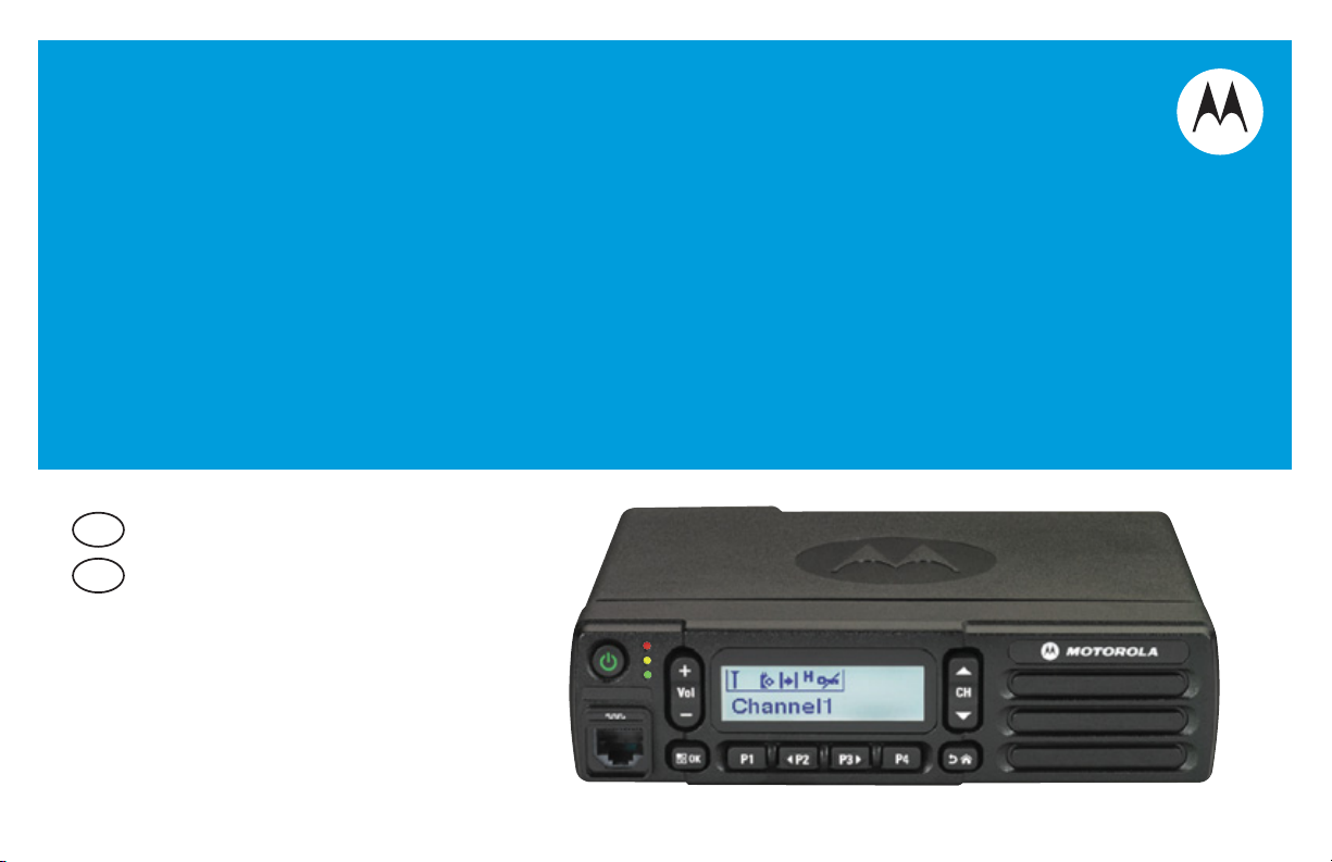
PROFESSIONAL DIGITAL TWO-WAY RADIO
MOTOTRBO
TM
XPR
TM
2500
ALPHANUMERIC DISPLAY MOBILE
EN
USER GUIDE
FRC
GUIDE DE L’UTILISATEUR

Declaration of Conformity
This declaration is applicable to your radio only if your radio is labeled with the FCC logo shown below.
DECLARATION OF CONFORMITY
Per FCC CFR 47 Part 2 Section 2.1077(a)
Responsible Party
Name: Motorola Solutions, Inc.
Address: 1303 East Algonquin Road, Schaumburg, IL 60196-1078, U.S.A.
Phone Number: 1-800-927-2744
Hereby declares that the product:
Model Name: XPR 2500
conforms to the following regulations:
FCC Part 15, subpart B, section 15.107(a), 15.107(d) and section 15.109(a)
Class B Digital Device
As a personal computer peripheral, this device complies with Part 15 of the FCC Rules. This device complies with Industry
Canada licence-exempt RSS standard(s). Operation is subject to the following two conditions:
1. This device may not cause harmful interference, and
2. This device must accept any interference received, including interference that may cause undesired operation.
Declaration of Conformity
English
i

Note: This equipment has been tested and found to comply with the limits for a Class B digital device, pursuant to part
15 of the FCC Rules. These limits are designed to provide reasonable protection against harmful interference in a
residential installation. This equipment generates, uses and can radiate radio frequency energy and, if not
installed and used in accordance with the instructions, may cause harmful interference to radio communications.
However, there is no guarantee that interference will not occur in a particular installation.
If this equipment does cause harmful interference to radio or television reception, which can be determined by
turning the equipment off and on, the user is encouraged to try to correct the interference by one or more of the
following measures:
• Reorient or relocate the receiving antenna.
• Increase the separation between the equipment and receiver.
• Connect the equipment into an outlet on a circuit different from that to which the receiver is connected.
• Consult the dealer or an experienced radio/TV technician for help.
Declaration of Conformity
ii
English

Contents
This User Guide contains all the information you need
to use the MOTOTRBO XPR 2500 Mobile Radios.
Declaration of Conformity . . . . . . . . . . . . . . . . . . . . . i
Important Safety Information . . . . . . . . . . . . . . . . . vii
Product Safety and RF Exposure Compliance . . vii
Software Version . . . . . . . . . . . . . . . . . . . . . . . . . . . vii
Computer Software Copyrights . . . . . . . . . . . . . . viii
. . . . . . . . . . . . . . . . . . . . . . . . . . . . . . . . . . . . . . . viii
Getting Started . . . . . . . . . . . . . . . . . . . . . . . . . . . . . . 1
How to Use This User Guide . . . . . . . . . . . . . . . . . . 1
What Your Dealer/System Administrator
Can Tell You . . . . . . . . . . . . . . . . . . . . . . . . . . . . . . . 2
Powering Up the Radio . . . . . . . . . . . . . . . . . . . . . . . 2
Adjusting the Volume . . . . . . . . . . . . . . . . . . . . . . . . 3
Identifying Radio Controls . . . . . . . . . . . . . . . . . . . . 3
Radio Controls . . . . . . . . . . . . . . . . . . . . . . . . . . . . . 4
Programmable Buttons . . . . . . . . . . . . . . . . . . . . . . . 5
Assignable Radio Functions . . . . . . . . . . . . . . . . . 5
Assignable Settings or Utility Functions . . . . . . . . . 6
Accessing the Programmed Functions . . . . . . . . . . . 7
Push-To-Talk (PTT) Button . . . . . . . . . . . . . . . . . . . . 7
Switching Between Conventional Analog and Digital
Mode . . . . . . . . . . . . . . . . . . . . . . . . . . . . . . . . . . . . . 8
IP Site Connect . . . . . . . . . . . . . . . . . . . . . . . . . . . . 9
Capacity Plus . . . . . . . . . . . . . . . . . . . . . . . . . . . . . . 9
Linked Capacity Plus . . . . . . . . . . . . . . . . . . . . . . . 10
Identifying Status Indicators . . . . . . . . . . . . . . . . . . 11
Display Icons . . . . . . . . . . . . . . . . . . . . . . . . . . . . . . 11
Call Icons . . . . . . . . . . . . . . . . . . . . . . . . . . . . . . . . 13
Mini Notice Icons . . . . . . . . . . . . . . . . . . . . . . . . . . . 13
LED Indicators . . . . . . . . . . . . . . . . . . . . . . . . . . . . 14
Indicator Tones . . . . . . . . . . . . . . . . . . . . . . . . . . . . 15
Audio Tones . . . . . . . . . . . . . . . . . . . . . . . . . . . . . . 15
Receiving and Making Calls . . . . . . . . . . . . . . . . . . 15
Selecting a Zone . . . . . . . . . . . . . . . . . . . . . . . . . . . 16
Selecting a Channel . . . . . . . . . . . . . . . . . . . . . . . . 16
Receiving and Responding to a Radio Call . . . . . . 17
Receiving and Responding to a Group Call . . . . . 17
Receiving and Responding to a Private Call . . . 18
Receiving an All Call . . . . . . . . . . . . . . . . . . . . . . 19
Receiving and Responding to a Selective Call . . 19
Making a Radio Call . . . . . . . . . . . . . . . . . . . . . . . . 20
Making a Group Call . . . . . . . . . . . . . . . . . . . . . . 20
Making a Private Call . . . . . . . . . . . . . . . . . . . . . 21
Making an All Call . . . . . . . . . . . . . . . . . . . . . . . . 22
Making a Selective Call . . . . . . . . . . . . . . . . . . . . 22
Contents
iii
English

Stopping a Radio Call . . . . . . . . . . . . . . . . . . . . . . 23
Talkaround . . . . . . . . . . . . . . . . . . . . . . . . . . . . . . . 23
Permanent Monitor . . . . . . . . . . . . . . . . . . . . . . . . . 24
Advanced Features . . . . . . . . . . . . . . . . . . . . . . . . . 25
Radio Check . . . . . . . . . . . . . . . . . . . . . . . . . . . . . 25
Sending a Radio Check . . . . . . . . . . . . . . . . . . . 25
Remote Monitor . . . . . . . . . . . . . . . . . . . . . . . . . . . 27
Initiating Remote Monitor . . . . . . . . . . . . . . . . . . 27
Stopping Remote Monitor . . . . . . . . . . . . . . . . . . 28
Scan Lists . . . . . . . . . . . . . . . . . . . . . . . . . . . . . . . . 29
Viewing an Entry in the Scan List . . . . . . . . . . . . 29
Editing the Scan List . . . . . . . . . . . . . . . . . . . . . . 29
Adding a New Entry to the Scan List . . . . . . . . 29
Deleting an Entry from the Scan List . . . . . . . . 30
Setting and Editing Priority for an Entry in the
Scan List . . . . . . . . . . . . . . . . . . . . . . . . . . . . . 30
Scan . . . . . . . . . . . . . . . . . . . . . . . . . . . . . . . . . . . . 31
Starting and Stopping Scan . . . . . . . . . . . . . . . . 32
Responding to a Transmission During a Scan . . 32
Deleting a Nuisance Channel . . . . . . . . . . . . . . . 33
Restoring a Nuisance Channel . . . . . . . . . . . . . . 33
Vote Scan . . . . . . . . . . . . . . . . . . . . . . . . . . . . . . . 33
Contacts Settings . . . . . . . . . . . . . . . . . . . . . . . . . 34
Contents
Making a Group Call from Contacts . . . . . . . . . . 34
Making a Private Call from Contacts . . . . . . . . . 35
iv
Assigning an Entry to a Programmable
Number Key . . . . . . . . . . . . . . . . . . . . . . . . . . . . 36
Removing the Association between Entry and
Programmable Number Key . . . . . . . . . . . . . . . 36
Setting Default Contact . . . . . . . . . . . . . . . . . . 37
Adding a New Contact . . . . . . . . . . . . . . . . . . . 38
Call Indicator Settings . . . . . . . . . . . . . . . . . . . . . . 38
Activating or Deactivating Call Ringers for
Call Alerts . . . . . . . . . . . . . . . . . . . . . . . . . . . . . . 38
Activating or Deactivating Call Ringers for
Private Calls . . . . . . . . . . . . . . . . . . . . . . . . . . . . 39
Activating or Deactivating Call Ringers for
Selective Call . . . . . . . . . . . . . . . . . . . . . . . . . . . 39
Escalating Alarm Tone Volume . . . . . . . . . . . . . . 40
Call Log Features . . . . . . . . . . . . . . . . . . . . . . . . . 41
Viewing Recent Calls . . . . . . . . . . . . . . . . . . . . . 41
Deleting a Call from a Call List . . . . . . . . . . . . . . 41
Deleting All Calls from a Call List . . . . . . . . . . . . 42
Call Alert Operation . . . . . . . . . . . . . . . . . . . . . . . . 43
Receiving and Responding to a Call Alert . . . . . 43
Making a Call Alert from the Contacts List . . . . . 43
Making a Call Alert with the One Touch Access
Button . . . . . . . . . . . . . . . . . . . . . . . . . . . . . . . . . 44
Emergency Operation . . . . . . . . . . . . . . . . . . . . . . 44
Receiving an Emergency Alarm . . . . . . . . . . . . . 45
Responding to an Emergency Alarm . . . . . . . . . 45
English

Sending an Emergency Alarm . . . . . . . . . . . . . . . 46
Sending an Emergency Alarm with Call . . . . . . . 47
Sending an Emergency Alarm with Voice to
Follow . . . . . . . . . . . . . . . . . . . . . . . . . . . . . . . . . 48
Reinitiating an Emergency Mode . . . . . . . . . . . . . 49
Exiting Emergency Mode . . . . . . . . . . . . . . . . . . . 50
Analog Status Update . . . . . . . . . . . . . . . . . . . . . . 50
Sending Status Update to Predefined Contact . . 50
Privacy . . . . . . . . . . . . . . . . . . . . . . . . . . . . . . . . . . 51
Analog Scrambling . . . . . . . . . . . . . . . . . . . . . . . . . 52
Turning Analog Scrambling On or Off . . . . . . . . . 52
Setting the Analog Scrambling Codes . . . . . . . . . 53
Multi-Site Controls . . . . . . . . . . . . . . . . . . . . . . . . . 53
Starting an Automatic Site Search . . . . . . . . . . . . 53
Stopping an Automatic Site Search . . . . . . . . . . . 54
Starting a Manual Site Search . . . . . . . . . . . . . . . 55
Security . . . . . . . . . . . . . . . . . . . . . . . . . . . . . . . . . 56
Radio Disable . . . . . . . . . . . . . . . . . . . . . . . . . . . 56
Radio Enable . . . . . . . . . . . . . . . . . . . . . . . . . . . . 57
Lone Worker . . . . . . . . . . . . . . . . . . . . . . . . . . . . . . 58
Notification List . . . . . . . . . . . . . . . . . . . . . . . . . . . . 58
Accessing the Notification List . . . . . . . . . . . . . . . 59
Auto-Range Transponder System (ARTS) . . . . . . . 59
Over-the-Air Programming (OTAP) . . . . . . . . . . . . . 60
Utilities . . . . . . . . . . . . . . . . . . . . . . . . . . . . . . . . . . 60
Turning the Radio Tones/Alerts On or Off . . . . . . 60
Setting the Tone Alert Volume Offset Level . . . . 61
Turning the Talk Permit Tone On or Off . . . . . . . 61
Turning the Power Up Alert Tone On or Off . . . . 62
Setting the Power Level . . . . . . . . . . . . . . . . . . . . 62
Adjusting the Display Brightness . . . . . . . . . . . . . 63
Turning Horns/Lights On or Off . . . . . . . . . . . . . . 63
Setting the Squelch Level . . . . . . . . . . . . . . . . . . 64
Turning the LED Indicators On or Off . . . . . . . . . 64
Language . . . . . . . . . . . . . . . . . . . . . . . . . . . . . . . 65
Turning the Voice Operating Transmission
(VOX) Feature On or Off . . . . . . . . . . . . . . . . . . . 65
Voice Announcement . . . . . . . . . . . . . . . . . . . . . . 66
Analog Mic AGC (Mic AGC-A) . . . . . . . . . . . . . . . 67
Digital Mic AGC (Mic AGC-D) . . . . . . . . . . . . . . . 67
Intelligent Audio . . . . . . . . . . . . . . . . . . . . . . . . . 68
Accessing General Radio Information . . . . . . . . . 68
Checking the Radio Alias and ID . . . . . . . . . . . 68
Checking the Firmware Version and Codeplug
Version . . . . . . . . . . . . . . . . . . . . . . . . . . . . . . . 69
Software Update . . . . . . . . . . . . . . . . . . . . . . . . 69
Site Information . . . . . . . . . . . . . . . . . . . . . . . . 70
Keypad Microphone Features . . . . . . . . . . . . . . . . 71
Using the Keypad . . . . . . . . . . . . . . . . . . . . . . . . . . 72
Turning Keypad Tones On or Off . . . . . . . . . . . . . 73
Additional Advanced Features . . . . . . . . . . . . . . . . 73
Contents
v
English

vi
Selecting a Zone by Alias Search . . . . . . . . . . . . 73
Initiating a Radio Check by Manual Dial . . . . . . 74
Initiating Remote Monitor by Manual Dial . . . . . 75
Making a Private Call by Manual Dial . . . . . . . . 75
Making a Group, Private or All Call with the
Programmable Number Key . . . . . . . . . . . . . . . 76
Making a Group, Private or All Call by Alias
Search . . . . . . . . . . . . . . . . . . . . . . . . . . . . . . . . 77
Viewing an Entry in the Scan List by Alias
Search . . . . . . . . . . . . . . . . . . . . . . . . . . . . . . . . . 78
Editing the Scan List by Alias Search . . . . . . . . . 78
Adding a New Entry to the Scan List . . . . . . . . 78
Deleting an Entry from the Scan List . . . . . . . . 79
Setting and Editing Priority for an Entry in the
Scan List . . . . . . . . . . . . . . . . . . . . . . . . . . . . . 80
Storing an Alias or ID from a Call List . . . . . . . . . 80
Making a Call Alert by Manual Dial . . . . . . . . . . 81
RSSI Values . . . . . . . . . . . . . . . . . . . . . . . . . . . . 81
Dual Tone Multi Frequency (DTMF) . . . . . . . . . . . . 82
Security . . . . . . . . . . . . . . . . . . . . . . . . . . . . . . . . . 82
Radio Disable via Manual Dial . . . . . . . . . . . . . . 82
Radio Enable via Manual Dial . . . . . . . . . . . . . . . 83
Password Lock Features . . . . . . . . . . . . . . . . . . . . 84
Contents
Accessing the Radio from Password . . . . . . . . . 84
Unlocking the Radio from Locked State . . . . . . . 85
Turning the Password Lock On or Off . . . . . . . . . 85
Changing the Password . . . . . . . . . . . . . . . . . . . 85
Front Panel Configuration (FPC) . . . . . . . . . . . . . . 86
Entering FPC Mode . . . . . . . . . . . . . . . . . . . . . . 86
Editing FPC Mode Parameters . . . . . . . . . . . . . . 87
Accessories . . . . . . . . . . . . . . . . . . . . . . . . . . . . . . . 88
Antennas . . . . . . . . . . . . . . . . . . . . . . . . . . . . . . . . 88
Audio . . . . . . . . . . . . . . . . . . . . . . . . . . . . . . . . . . . 88
Cables . . . . . . . . . . . . . . . . . . . . . . . . . . . . . . . . . . 89
Mounting Kits . . . . . . . . . . . . . . . . . . . . . . . . . . . . . 89
Miscellaneous Accessories . . . . . . . . . . . . . . . . . . 89
Appendix: Maritime Radio Use in the VHF Frequency
Range . . . . . . . . . . . . . . . . . . . . . . . . . . . . . . . . . . . . 90
Special Channel Assignments . . . . . . . . . . . . . . . . 90
Emergency Channel . . . . . . . . . . . . . . . . . . . . . . 90
Non-Commercial Call Channel . . . . . . . . . . . . . . 90
Operating Frequency Requirements . . . . . . . . . . . 91
Limited Warranty . . . . . . . . . . . . . . . . . . . . . . . . . . . 93
Notes . . . . . . . . . . . . . . . . . . . . . . . . . . . . . . . . . . . . 96
English

Important Safety Information
RF Energy Exposure and Product Safety Guide
for Mobile Two-Way Radios
ATTENTION!
This radio is restricted to Occupational use only.
Before using the radio, read the RF Energy Exposure and
Product Safety Guide for Mobile Two-Way Radios which
contains important operating instructions for safe usage
and RF energy awareness and control for Compliance
with applicable standards and Regulations.
For a list of Motorola-approved antennas and other
accessories, visit the following website:
http://www.motorolasolutions.com
Any modification to this device, not expressly authorized by
Motorola, may void the user’s authority to operate this device.
Under Industry Canada regulations, this radio transmitter may
only operate using an antenna of a type and maximum (or
lesser) gain approved for the transmitter by Industry Canada. To
reduce potential radio interference to other users, the antenna
type and its gain should be so chosen that the equivalent
isotropically radiated power (e.i.r.p.) is not more than that
necessary for successful communication.
This radio transmitter has been approved by Industry Canada to
operate with Motorola-approved antenna with the maximum
permissible gain and required antenna impedance for each
antenna type indicated. Antenna types not included in this list,
having a gain greater than the maximum gain indicated for that
type, are strictly prohibited for use with this device.
Software Version
All the features described in the following sections are
supported by the radio's software version R01.00.00.
See Checking the Firmware Version and Codeplug
Version on page 69 to determine your radio's software
version.
Please check with your dealer or system administrator
for more details of all the features supported.
Important Safety Information
vii
English

Computer Software Copyrights
The Motorola products described in this manual may
include copyrighted Motorola computer programs stored
in semiconductor memories or other media. Laws in the
United States and other countries preserve for Motorola
certain exclusive rights for copyrighted computer
programs including, but not limited to, the exclusive right
to copy or reproduce in any form the copyrighted
computer program. Accordingly, any copyrighted
Motorola computer programs contained in the Motorola
products described in this manual may not be copied,
reproduced, modified, reverse-engineered, or distributed
in any manner without the express written permission of
Motorola. Furthermore, the purchase of Motorola
products shall not be deemed to grant either directly or by
implication, estoppel, or otherwise, any license under the
copyrights, patents or patent applications of Motorola,
except for the normal non-exclusive license to use that
arises by operation of law in the sale of a product.
Computer Software Copyrights
TM
The AMBE+2
this product is protected by intellectual property rights
including patent rights, copyrights and trade secrets of
Digital Voice Systems, Inc.
This voice coding Technology is licensed solely for use
within this Communications Equipment. The user of this
Technology is explicitly prohibited from attempting to
decompile, reverse engineer, or disassemble the Object
Code, or in any other way convert the Object Code into a
human-readable form.
U.S. Pat. Nos. #5,870,405, #5,826,222, #5,754,974,
#5,701,390, #5,715,365, #5,649,050, #5,630,011,
#5,581,656, #5,517,511, #5,491,772, #5,247,579,
#5,226,084 and #5,195,166.
voice coding Technology embodied in
Open Source Software Legal Notices
This Motorola Product contains Open Source Software. For
more information regarding licenses, acknowledgements,
required copyright notices, and other usage terms, refer to the
Documentation for this Motorola Product at:
https://businessonline.motorolasolutions.com
viii
English
Getting Started
Take a moment to review the following:
How to Use This User Guide. . . . . . . . . . . . . . . . . . . . . page 1
What Your Dealer/System Administrator
Can Tell You. . . . . . . . . . . . . . . . . . . . . . . . . . . . . . . . page 2
Powering Up the Radio . . . . . . . . . . . . . . . . . . . . . . . . . page 2
Adjusting the Volume. . . . . . . . . . . . . . . . . . . . . . . . . . . page 3
How to Use This User Guide
This User Guide covers the basic operation of the MOTOTRBO
Mobiles.
However, your dealer or system administrator may have
customized your radio for your specific needs. Check with your
dealer or system administrator for more information.
Throughout this publication, the icons below are used to
indicate features supported in either the conventional Analog
mode or conventional Digital mode:
Indicates a conventional Analog Mode-Only feature.
Indicates a conventional Digital Mode-Only feature.
For features that are available in both Analog and Digital
modes, no icon is shown.
For features that are available in a conventional multi-site
mode, see IP Site Connect on page 9 for more information.
Selected features are available in the single-site trunking mode,
Capacity Plus. See Capacity Plus on page 9 for more
information.
Selected features are also available in the multi-site trunking
mode, Linked Capacity Plus. See Linked Capacity Plus on
page 10 for more information.
Getting Started
1
English
What Your Dealer/System Administrator
Can Tell You
You can consult your dealer or system administrator about the
following:
• Is your radio programmed with any preset conventional
channels?
• Which buttons have been programmed to access other
features?
• What optional accessories may suit your needs?
• What are the best radio usage practices for effective
communication?
• What maintenance procedures will help promote longer radio
life?
Getting Started
2
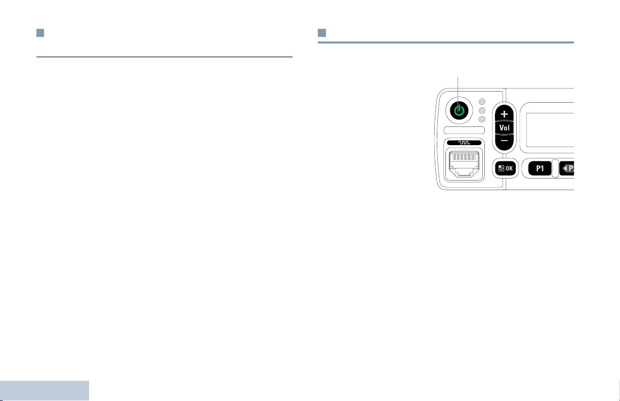
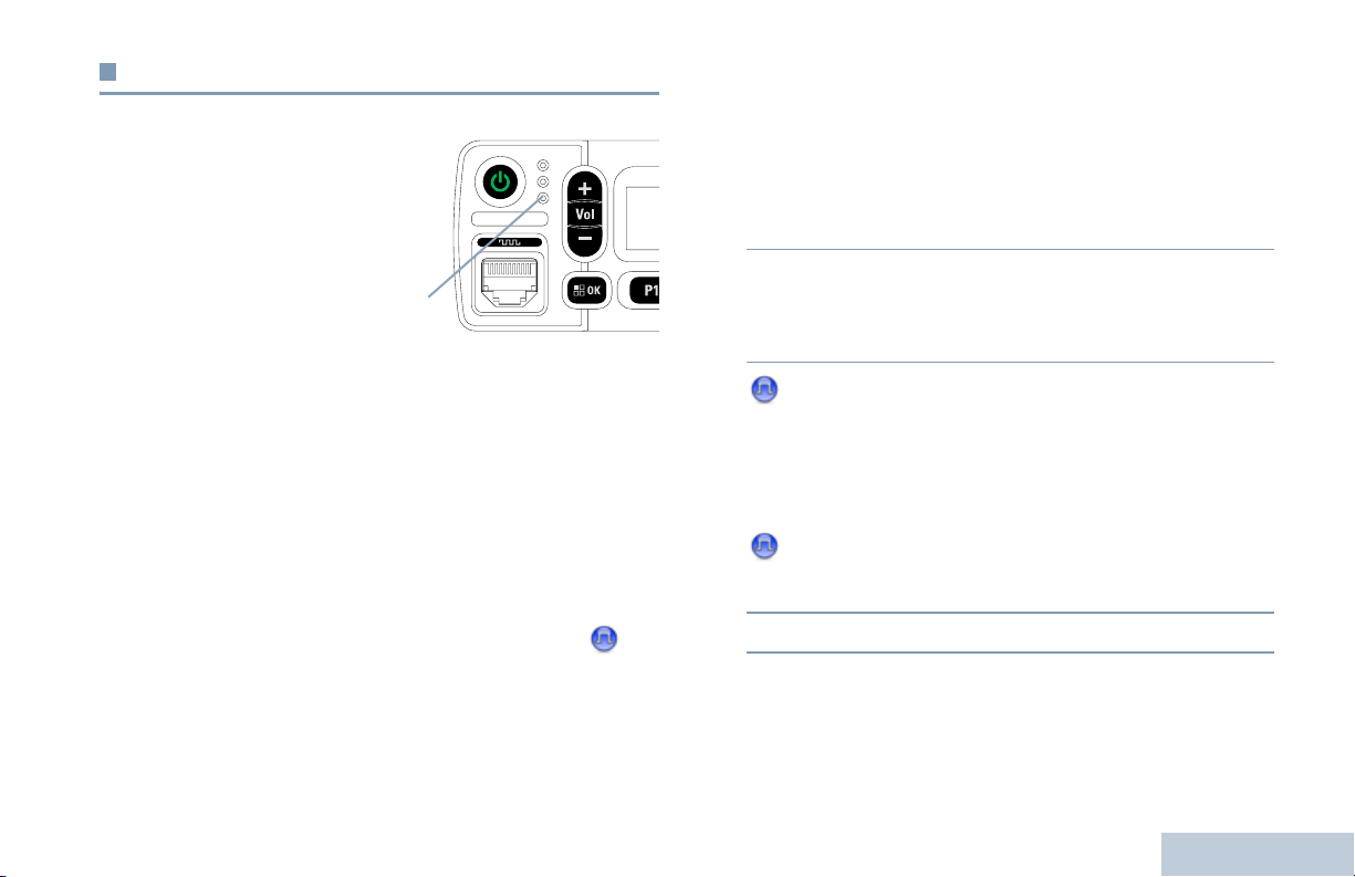
Powering Up the Radio
Press the On/Off
Button briefly. You see
MOTOTRBO (TM) on the
radio’s display
momentarily, followed
by a welcome message
or welcome image.
The green LED lights
up and the Home
screen lights up.
A brief tone sounds,
indicating that the
power up test is
successful.
NOTE: There is no power up tone if the radio tones/alerts
function is disabled (see Turning the Radio Tones/
Alerts On or Off on page 60).
If your radio does not power up, contact your dealer.
To turn off the radio, press and hold the On/Off Button until you
see
Powering Down on the radio’s display.
NOTE: If the radio is locked up and unresponsive to button
presses, press and hold the On/Off Button for at least 7
seconds. This will force a radio reset.
On/Off Button
English
Your radio may take up to 7 seconds to completely turn
off.
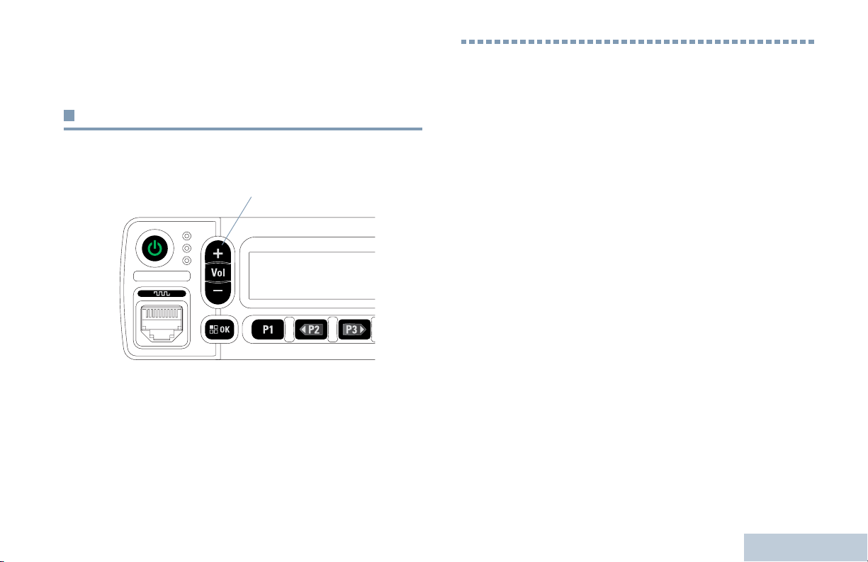
Adjusting the Volume
To increase the volume, press the volume “ + ” button.
Volume Up/Down Button
To decrease the volume, press the volume “ – ” button.
Your radio can be programmed to have a minimum volume
offset where the volume level cannot be lowered past the
programmed minimum volume. Check with your dealer or
system administrator for more information.
Identifying Radio Controls
Identifying Radio Controls
Take a moment to review the following:
Radio Controls . . . . . . . . . . . . . . . . . . . . . . . . . . . . . . . .page 4
Programmable Buttons . . . . . . . . . . . . . . . . . . . . . . . . . page 5
Accessing the Programmed Functions . . . . . . . . . . . . .page 7
Push-To-Talk (PTT) Button . . . . . . . . . . . . . . . . . . . . . . .page 7
Switching Between Conventional Analog and
Digital Mode . . . . . . . . . . . . . . . . . . . . . . . . . . . . . . . .page 8
IP Site Connect . . . . . . . . . . . . . . . . . . . . . . . . . . . . . . .page 9
Capacity Plus . . . . . . . . . . . . . . . . . . . . . . . . . . . . . . . . . page 9
Linked Capacity Plus . . . . . . . . . . . . . . . . . . . . . . . . . .page 10
English
3
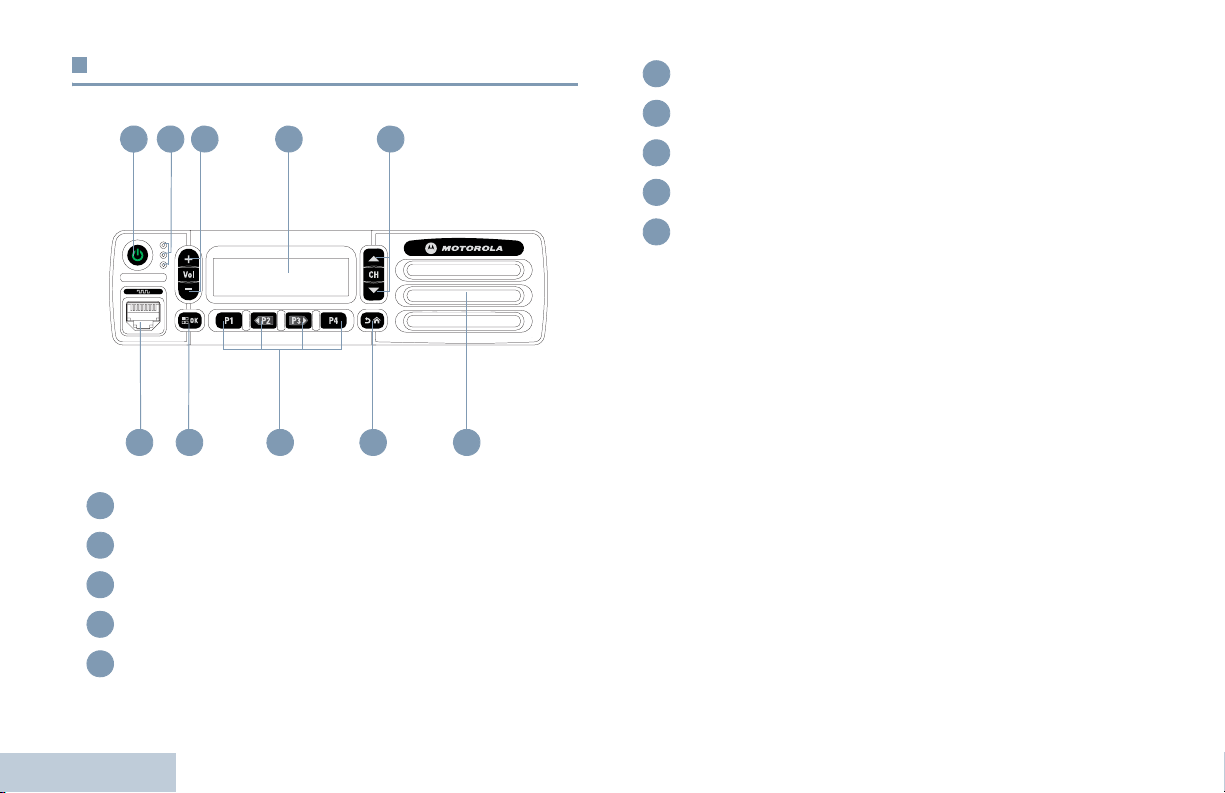
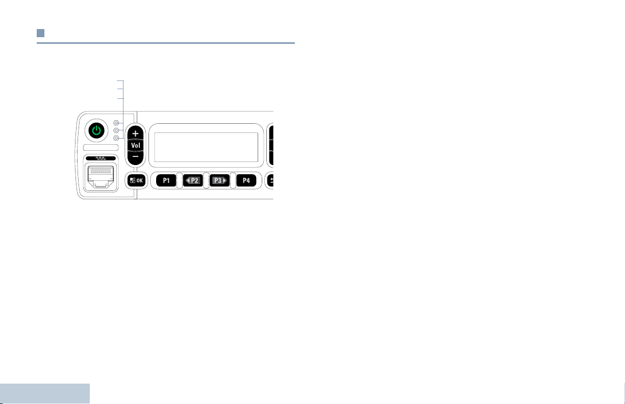
Radio Controls
2
1
Speaker
6
Return/Home Button
7
43
5
Front Programmable Buttons
8
Menu/OK Button
9
Accessory Connector
10
9 78
10
On/Off Button
1
LED Indicators
2
Volume Up/Down Button
3
Display
4
Identifying Radio Controls
Channel Up/Down Button
5
4
English
6

Programmable Buttons
Your dealer can program the programmable buttons as
shortcuts to radio functions or up to a maximum of six (6)
preset channels/groups depending on the duration of a button
press:
• Short press – Pressing and releasing rapidly.
• Long press – Pressing and holding for the programmed
duration.
• Hold down – Keeping the button pressed.
NOTE: The programmed duration of a button press is
applicable for all assignable radio/utility functions or
settings. See Emergency Operation on page 44 for
more information on the programmed duration of the
Emergency button.
Assignable Radio Functions
Analog Scrambling – Toggles analog scrambling on or
off.
Emergency – Depending on the programming, initiates or
cancels an Emergency alarm or call.
Intelligent Audio On/Off – Toggles Intelligent Audio on or off.
Manual Dial – Depending on the programming, initiates a
Private call by keying in any subscriber ID.
Manual Site Roam*
Monitor – Monitors a selected channel for activity.
Notifications – Provides direct access to the Notifications List.
Nuisance Channel Delete*
unwanted channel, except for the Selected Channel, from the
scan list. The Selected Channel refers to the user’s selected
zone/channel combination from which scan is initiated.
One Touch Access – Directly initiates a predefined
Private, Phone or Group Call or a Call Alert.
Permanent Monitor*
radio traffic until function is disabled.
‡
– Starts the manual site search.
‡
– Temporarily removes an
‡
– Monitors a selected channel for all
Identifying Radio Controls
Contacts – Provides direct access to the contacts list.
Call Alert – Provides direct access to the contacts list for you to
select a contact to whom a Call Alert can be sent.
Call Log – Selects the call log list.
Privacy – Toggles privacy on or off.
Radio Alias and ID – Provides radio alias and ID.
Radio Check – Determines if a radio is active in a system.
* Not applicable in Capacity Plus
‡
Not applicable in Linked Capacity Plus
English
5

Radio Enable – Allows a target radio to be remotely
enabled.
Radio Disable – Allows a target radio to be remotely
disabled.
Remote Monitor – Turns on the microphone of a target
radio without it giving any indicators.
Repeater/Talkaround*
and communicating directly with another radio.
‡
Scan*
– Toggles scan on or off.
Site Info* – Displays current Linked Capacity Plus site name
and ID. Plays site announcement voice messages for the
current site (this function is unavailable when Voice
Announcement is disabled).
Site Lock On/Off* – Toggles the automatic site roam on or
off.
Status – Selects the status list menu.
Transmit Interrupt Remote Dekey – Stops the
transmission of a remote monitored radio without giving any
indicators, or an ongoing interruptible call to free the channel.
Identifying Radio Controls
Voice Announcement for Channel – Plays zone and channel
announcement voice messages for the current channel. This
function is unavailable when Voice Announcement is disabled.
6
‡
– Toggles between using a repeater
Voice Announcement On/Off – Toggles Voice Announcement
on or off.
Voice Operating Transmission (VOX) – Toggles VOX on or
off.
Zone Toggle – Allows radio to switch between zones.
Assignable Settings or Utility Functions
All Tones/Alerts – Toggles all tones and alerts on or off.
Analog Scrambling Codes – Toggles scrambling codes
between 3.29KHz and 3.39KHz.
Backlight – Adjusts the brightness level.
Channel Up/Down – Depending on the programming, changes
channel to previous or next channel.
Power Level – Toggles transmit power level between high and
low.
Squelch – Toggles squelch level between tight and
normal.
* Not applicable in Capacity Plus
‡
Not applicable in Linked Capacity Plus
English
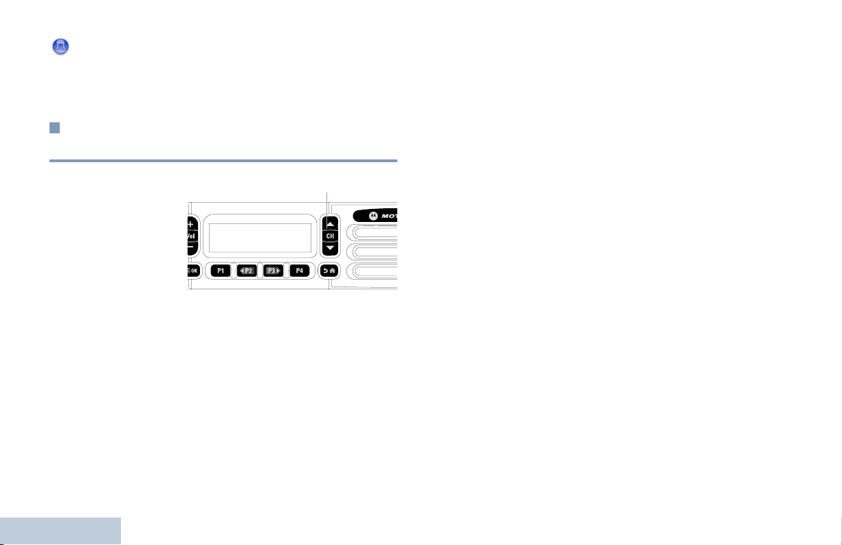
Accessing the Programmed Functions
Push-To-Talk (PTT) Button
You can access various radio functions through one of the
following ways:
• A short or long press of the relevant programmable buttons.
OR
• Use the Menu Navigation Buttons as follows:
1 To access the menu, press the g button. Press the
appropriate Left/ Right Navigation button (b or c ) to
access the menu functions.
2 To select a function or enter a sub-menu, press the g
button.
3 To go back one menu level, or to return to the previous
screen, press the
return to the Home screen.
The Menu Navigation Buttons are also available on a keypad
microphone (see Using the Keypad on page 72).
NOTE: Your radio automatically exits the menu after a period
of inactivity and returns to your Home screen.
e button. Long press the e button to
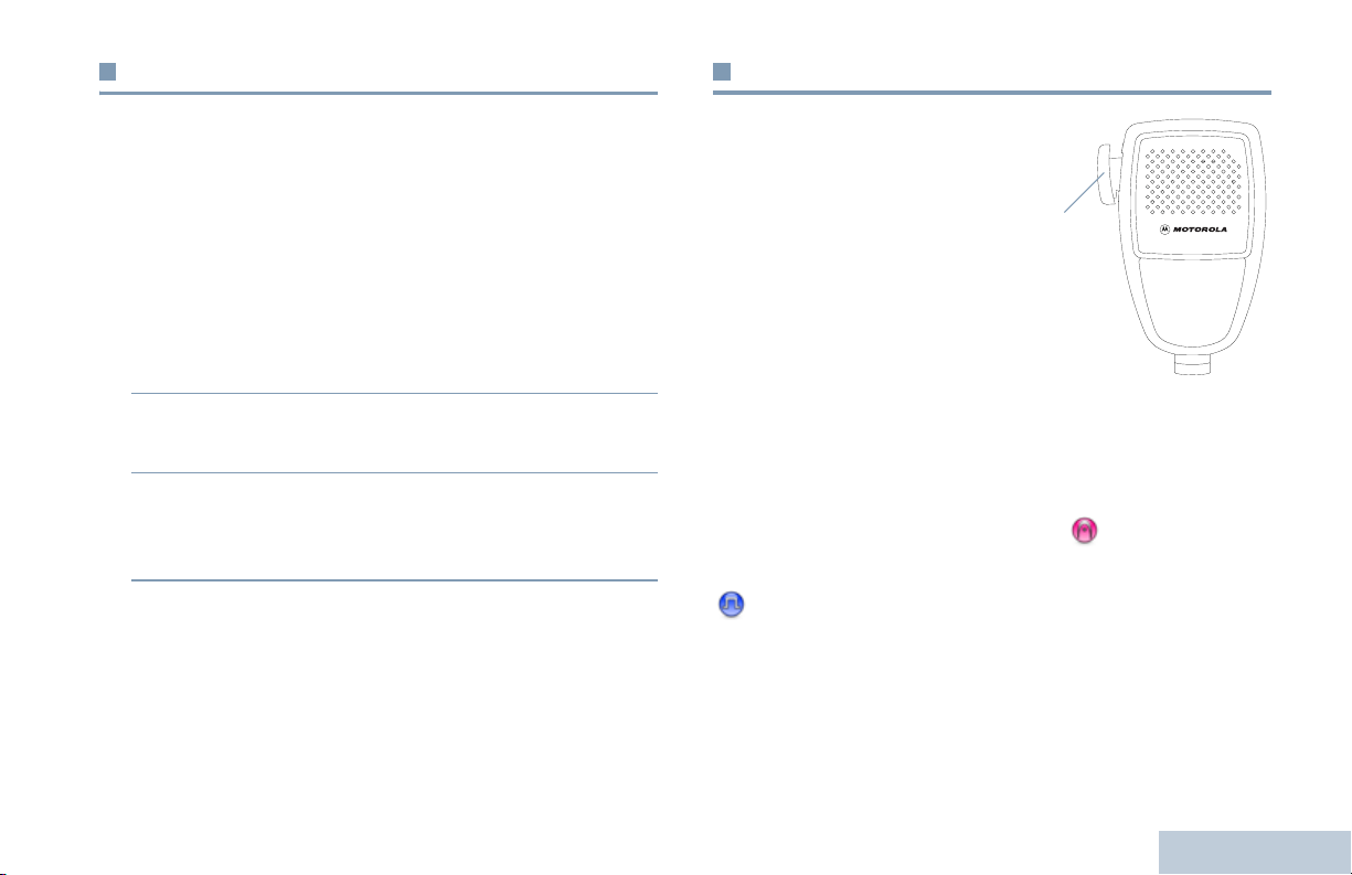
The PTT button on the side of
the microphone serves two
basic purposes:
• While a call is in progress,
the PTT button allows the
radio to transmit to other
radios in the call.
Press and hold down PTT
button to talk. Release the
PTT button to listen.
The microphone is activated when the PTT button is pressed.
PTT Button
• While a call is not in progress, the PTT button is used to make
a new call (see Making a Radio Call on page 20).
If the Talk Permit Tone (see Turning the Talk Permit Tone On
or Off on page 61) or the PTT Sidetone is enabled, wait
until the short alert tone ends before talking.
During a call, if the Channel Free Indication feature is
enabled on your radio (programmed by your dealer), you
hear a short alert tone the moment the target radio (the
radio that is receiving your call) releases the PTT button,
indicating the channel is free for you to respond.
Identifying Radio Controls
English
7
You will also hear a continuous talk prohibit tone, if your
call is interrupted, indicating that you should release the
PTT button, for example when the radio receives an
Emergency Call.
To use the Left/ Right Navigation buttons, while in the
Home Screen of the required Zone, press
to select the required channel.
b or c
Switching Between Conventional Analog
and Digital Mode
Each channel in your
radio can be configured
as a conventional
analog or conventional
digital channel.
To switch between an
analog or a digital
channel, use the
Channel Up or Channel Down buttons
When switching from digital to analog mode, certain features
are unavailable. Icons for the digital features (such as
Messages) reflect this change by appearing ‘grayed out’.
Disabled features are hidden in the menu.
Your radio also has features available in both analog and digital
mode. However, the minor differences in the way each feature
works does NOT affect the performance of your radio.
Identifying Radio Controls
NOTE: Your radio also switches between digital and analog
modes during a dual mode scan (see Scan on
8
page 31).
Channel Up/ Down Button
To use the programmed Channel Up or Channel
Down buttons, while in the Home Screen of the
required Zone, press Channel Up or Channel Down
to select the required channel.
English

IP Site Connect
This feature allows your radio to extend conventional
communication beyond the reach of a single site, by connecting
to different available sites which are connected via an Internet
Protocol (IP) network.
When the radio moves out of range from one site and into the
range of another, it connects to the new site's repeater to send
or receive calls/data transmissions. Depending on your settings,
this is done automatically or manually.
If the radio is set to do this automatically, it scans through all
available sites when the signal from the current site is weak or
when the radio is unable to detect any signal from the current
site. It then locks on to the repeater with the strongest Received
Signal Strength Indicator (RSSI) value.
In a manual site search, the radio searches for the next site in
the roam list that is currently in range (but which may not have
the strongest signal) and locks on to it.
NOTE: Each channel can only have either Scan or Roam
enabled, not both at the same time.
Channels with this feature enabled can be added to a particular
roam list. The radio searches the channel(s) in the roam list
during the automatic roam operation to locate the best site.
A roam list supports a maximum of 16 channels (including the
Selected Channel).
NOTE: You cannot manually add or delete an entry to the
roam list. Check with your dealer or system
administrator for more information.
Capacity Plus
Capacity Plus is a single-site trunking configuration of the
MOTOTRBO radio system, which uses a pool of channels to
support hundreds of users and up to 254 Groups. This feature
allows your radio to efficiently utilize the available number of
programmed channels while in Repeater Mode.
Icons of features not applicable to Capacity Plus are not
available in the menu. You hear a negative indicator tone if you
try to access a feature not applicable to Capacity Plus via a
programmable button press.
Your radio also has features that are available in conventional
digital mode, IP Site Connect, Capacity Plus and Linked
Capacity Plus. However, the minor differences in the way each
feature works does NOT affect the performance of your radio.
Check with your dealer or system administrator for more
information on this configuration.
Identifying Radio Controls
9
English

Linked Capacity Plus
Linked Capacity Plus is a multi-site multi-channel trunking
configuration of the MOTOTRBO radio system, combining the
best of both Capacity Plus and IP Site Connect configurations.
Linked Capacity Plus allows your radio to extend trunking
communication beyond the reach of a single site, by connecting
to different available sites which are connected via an Internet
Protocol (IP) network. It also provides an increase in capacity by
efficiently utilizing the combined available number of
programmed channels supported by each of the available sites.
When the radio moves out of range from one site and into the
range of another, it connects to the new site's repeater to send
or receive calls/data transmissions. Depending on your settings,
this is done automatically or manually.
If the radio is set to do this automatically, it scans through all
available sites when the signal from the current site is weak or
when the radio is unable to detect any signal from the current
site. It then locks on to the repeater with the strongest Received
Signal Strength Indicator (RSSI) value.
In a manual site search, the radio searches for the next site in
the roam list that is currently in range (but which may not have
the strongest signal) and locks on to it.
Identifying Radio Controls
Any channel with Linked Capacity Plus enabled can be added
to a particular roam list. The radio searches these channels
during the automatic roam operation to locate the best site.
10
NOTE: You cannot manually add or delete an entry to the
roam list. Check with your dealer or system
administrator for more information.
Similar to Capacity Plus, icons of features not applicable to
Linked Capacity Plus are not available in the menu. You hear a
negative indicator tone if you try to access a feature not
applicable to Linked Capacity Plus via a programmable button
press.
Check with your dealer or system administrator for more
information on this configuration.
English
Identifying Status Indicators
Your radio indicates its operational status through the following:
Display Icons . . . . . . . . . . . . . . . . . . . . . . . . . . . . . . . . page 11
Call Icons. . . . . . . . . . . . . . . . . . . . . . . . . . . . . . . . . . . page 13
Mini Notice Icons . . . . . . . . . . . . . . . . . . . . . . . . . . . . . page 13
LED Indicators. . . . . . . . . . . . . . . . . . . . . . . . . . . . . . . page 14
Audio Tones . . . . . . . . . . . . . . . . . . . . . . . . . . . . . . . . . page 15
Indicator Tones . . . . . . . . . . . . . . . . . . . . . . . . . . . . . . page 15
Display Icons
The liquid crystal display (LCD) of your radio shows the radio
status, text entries, and menu entries.
The following are icons that appear on the status bar at the top
of the radio’s display. Icons are displayed on the status bar,
arranged left-to-right, in order of appearance/usage and are
channel specific.
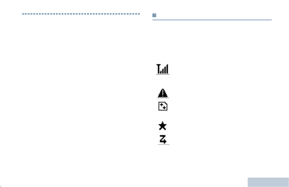
Received Signal Strength Indicator (RSSI)
The number of bars displayed represents the radio
signal strength. Four bars indicate the strongest
signal. This icon is only displayed while receiving.
Emergency
Radio is in Emergency mode.
High Volume Data
Radio is receiving high volume data and channel is
busy.
Notification
Notification List has one or more missed events.
‡
Scan*
Scan feature is enabled.
* Not applicable in Capacity Plus
‡
Not applicable in Linked Capacity Plus
Identifying Status Indicators
English
11

Scan – Priority 1*
Radio detects activity on channel/group designated
as Priority 1).
Scan – Priority 2*
Radio detects activity on channel/group designated
as Priority 2.
Vote Scan
Vote scan feature is enabled.
Monitor
Selected channel is being monitored.
Talkaround*
In the absence of a repeater, radio is currently
configured for direct radio to radio communication.
Site Roaming*
The site roaming feature is enabled.
Secure
The Privacy feature is enabled.
Unsecure
The Privacy feature is disabled.
Over-the-Air Programming Delay Timer
Identifying Status Indicators
Indicates time left before automatic restart of radio.
Tones Disable
Tones are turned off.
12
‡
‡
‡
Power High
Radio is set at High power.
English
Call Icons
Mini Notice Icons
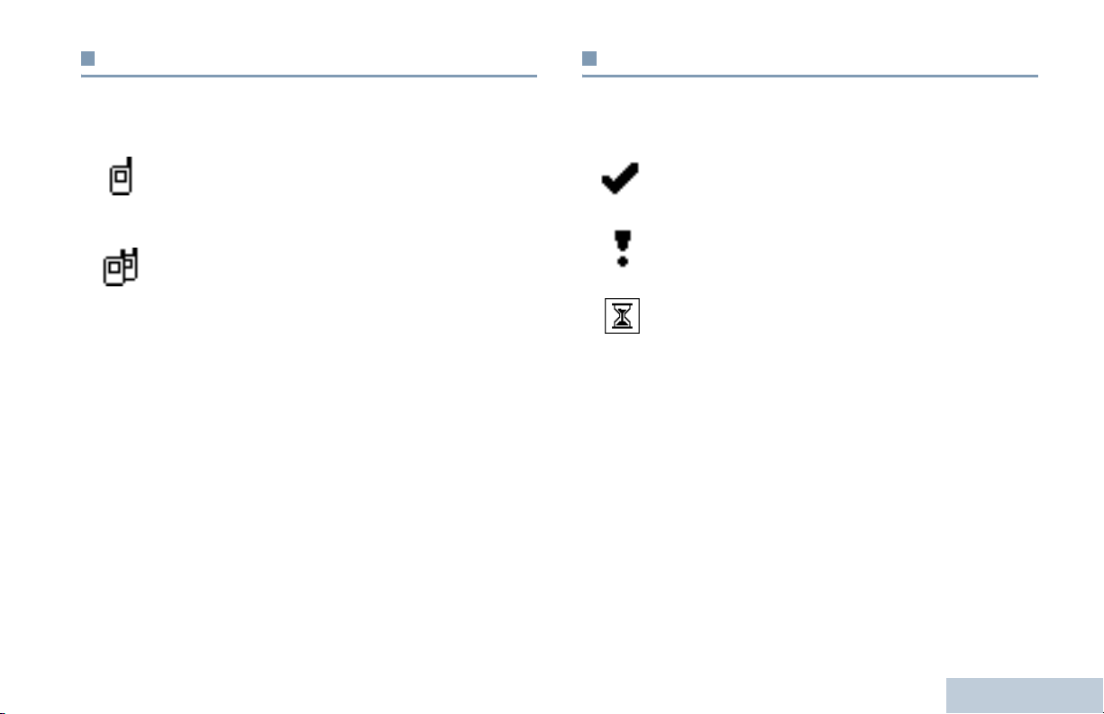
The following icons appear on the radio’s display during a call.
These icons also appear in the Contacts list to indicate alias or
ID type.
Private Call
Indicates a Private Call in progress.
In the Contacts list, it indicates a subscriber alias
(name) or ID (number).
Group Call/All Call
Indicates a Group Call or All Call in progress.
In the Contacts list, it indicates a group alias (name)
or ID (number).
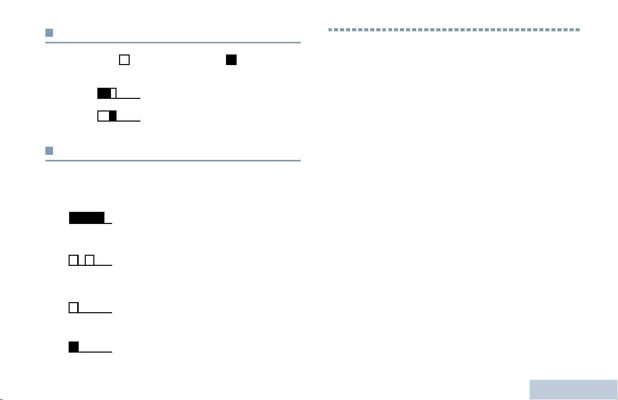
The following icons appear momentarily on the radio’s display
after an action to perform task is taken.
Successful Transmission (Positive)
Successful action taken.
Failed Transmission (Negative)
Failed action taken.
Transmission in Progress (Transitional)
Transmitting. This dynamic icon is seen before
indication for Successful Transmission or Failed
Transmission.
Identifying Status Indicators
English
13
LED Indicators
LED indicators show the operational status of your radio.
Red
Yellow
Green
Blinking red – Radio is receiving an emergency transmission
or has failed the self-test upon powering up, or has moved out
of range if radio is configured with Auto-Range Transponder
System.
Solid green – Radio is powering up, or transmitting.
Blinking green – Radio is receiving a non-privacy-enabled call
or data, or detecting activity or retrieving Over-the-Air
Programming transmissions over the air.
Double blinking green – Radio is receiving a privacy-enabled
Identifying Status Indicators
call or data.
Solid yellow – Radio is monitoring a conventional channel.
14
Blinking yellow – Radio is scanning for activity or receiving a
Call Alert, or all local Linked Capacity Plus channels are busy.
Double blinking yellow – Radio is no longer connected to the
repeater while in Capacity Plus or Linked Capacity Plus, all
Capacity Plus channels or Linked Capacity Plus channels are
currently busy, Auto Roaming is enabled, radio is actively
searching for a new site. Also indicates radio has yet to respond
to a group call alert, or radio is locked.
While in conventional mode, when the green LED blinks, it
indicates the radio detects activity over the air. Due to the
nature of the digital protocol, this activity may or may not affect
the radio's programmed channel.
NOTE: For Capacity Plus and Linked Capacity Plus, there is
no LED indication when the radio is detecting activity
over the air.
English
Indicator Tones
High pitched tone Low pitched tone
Positive Indicator Tone
Negative Indicator Tone
Audio Tones
Alert tones provide you with audible indications of the radio’s
status or the radio’s response to data received.
Continuous Tone A monotone sound. Sounds
continuously until termination.
Periodic Tone Sounds periodically depending on the
duration set by the radio. Tone starts,
stops, and repeats itself.
Repetitive Tone A single tone that repeats itself until it is
terminated by the user.
Receiving and Making Calls
Receiving and Making Calls
Once you understand how your MOTOTRBO Mobile is
configured, you are ready to use your radio.
Use this navigation guide to familiarize yourself with the basic
Call features:
Selecting a Zone . . . . . . . . . . . . . . . . . . . . . . . . . . . . . page 16
Selecting a Channel . . . . . . . . . . . . . . . . . . . . . . . . . . . page 16
Receiving and Responding to a Radio Call . . . . . . . . . page 17
Making a Radio Call. . . . . . . . . . . . . . . . . . . . . . . . . . . page 20
Stopping a Radio Call. . . . . . . . . . . . . . . . . . . . . . . . . .page 23
Talkaround . . . . . . . . . . . . . . . . . . . . . . . . . . . . . . . . . . page 23
Permanent Monitor. . . . . . . . . . . . . . . . . . . . . . . . . . . .page 24
Momentary Tone Sounds only once for a short period of
time defined by the radio.
15
English

Selecting a Zone
Selecting a Channel
A zone is a group of channels. Your radio supports up to 128
channels and 25 zones, with a maximum of 128 channels per
zone.
Use the following procedure to select a zone.
Procedure:
Press the programmed Zone button and proceed to Step 3.
OR
Follow the procedure below.
1 g to access the menu.
2 b or c to Zone and press g to select.
3 The current zone is displayed and indicated by a 9.
4 b or c to the required zone and press g to select.
5 The display shows <Zone> Selected momentarily and
returns to the selected zone screen.
NOTE: You can also select a zone by alias search on a keypad
microphone. See Selecting a Zone by Alias Search
on page 73.
Receiving and Making Calls
Transmissions are sent and received on a channel. Depending
on your radio's configuration, each channel may have been
programmed differently to support different groups of users or
supplied with different features. After selecting the required
zone, select the channel you require to transmit or receive on.
Procedure:
Select a channel by using the Channel Up/ Down buttons.
• Left/Right Navigation buttons, OR
• Channel Up/Down buttons, OR
• The programmed Channel Up or Channel Down buttons
See Selecting a Zone on page 16 for more information on
selecting your required zone.
See Switching Between Conventional Analog and Digital
Mode on page 8 for information about Channel Up/ Down
buttons.
16
English
Receiving and Responding to a Radio Call
Once the channel, subscriber
alias or ID, or group alias or ID
is displayed, you can proceed
to receive and respond to
calls.
Receiving and Responding to a Group Call
To receive a call made to a group of users, your radio must be
configured as part of that group.
Procedure:
When you receive a Group Call (while on the Home screen):
1 The green LED blinks.
Receiving and Making Calls
The green LED lights up
while the radio is transmitting
and blinks when the radio is
receiving.
NOTE: The green LED lights up while the radio is transmitting
and double blinks when the radio is receiving a privacyenabled call.
To unscramble a privacy-enabled call, your radio must
have the same Privacy Key, or the same Key Value
and Key ID (programmed by your dealer) as the
transmitting radio (the radio you are receiving the call
from).
See Privacy on page 51 for more information.
Green
LED
2 The caller ID information appears in the top right corner. The
first text line displays the Group Call icon and the group call
alias. Your radio unmutes and the incoming call sounds
through the radio's speaker.
3 If the Channel Free Indication feature is enabled, you
hear a short alert tone the moment the transmitting radio
releases the PTT button, indicating the channel is free for
you to respond.
Press the PTT button to respond to the call.
OR
If the Voice Interrupt feature is enabled, press the PTT
button to stop the current call from the transmitting radio and
free the channel for you to talk/respond.
4 The green LED lights up.
17
English

5 Wait for the Talk Permit Tone to finish (if enabled) and
speak clearly into the microphone.
OR
Wait for the PTT Sidetone to finish (if enabled) and
speak clearly into the microphone.
6 Release the PTT button to listen.
7 If there is no voice activity for a predetermined period of
time, the call ends.
3 If the Channel Free Indication feature is enabled, you
hear a short alert tone the moment the transmitting radio
releases the PTT button, indicating the channel is free for
you to respond.
Press the PTT button to respond to the call.
OR
If the Voice Interrupt feature is enabled, press the PTT
button to stop the current call from the transmitting radio and
free the channel for you to talk/respond.
See Making a Group Call on page 20 for details on making a
Group Call.
Receiving and Responding to a Private Call
A Private Call is a call from an individual radio to another
individual radio.
Procedure:
When you receive a Private Call:
1 The green LED blinks.
2 The first text line shows the Private Call icon and the caller
alias. Your radio unmutes and the incoming call sounds
through the radio's speaker.
Receiving and Making Calls
18
English
4 The green LED lights up.
5 Wait for the Talk Permit Tone to finish (if enabled) and
speak clearly into the microphone.
6 Release the PTT button to listen.
7 If there is no voice activity for a predetermined period of
time, the call ends.
8 The display shows Call Ended.
See Making a Private Call on page 21 for details on making a
Private Call.

Receiving an All Call
An All Call is a call from an individual radio to every radio on the
channel. It is used to make important announcements requiring
the user’s full attention.
Procedure:
When you receive an All Call:
1 A tone sounds and the green LED blinks.
2 The caller ID information appears in the top right corner. The
first text line displays the Group Call icon and All Call.
Your radio unmutes and the incoming call sounds through
the radio's speaker.
3 Once the All Call ends, the radio returns to the previous
screen before receiving the call. An All Call does not wait for
a predetermined period of time before ending.
If the Channel Free Indication feature is enabled, you
hear a short alert tone the moment the transmitting radio
releases the PTT button, indicating the channel is now
available for use.
You cannot respond to an All Call.
See Making an All Call on page 22 for details on making an All
Call.
NOTE: The radio stops receiving the All Call if you switch to a
different channel while receiving the call.
During an All Call, you are not able to continue with
any menu navigation or editing until the call ends.
Receiving and Responding to a Selective Call
A Selective Call is a call from an individual radio to another
individual radio. It is a Private Call on an analog system.
Procedure:
When you receive a Selective Call:
1 The green LED blinks.
2 The first text line shows the Private Call icon. The radio
displays Selective Call or Alert with Call. Your radio
unmutes and the incoming call sounds through the radio's
speaker.
3 Press the PTT button to respond to the call.
4 The green LED lights up.
5 Wait for the Talk Permit Tone to finish (if enabled) and
speak clearly into the microphone.
6 Release the PTT button to listen.
7 If there is no voice activity for a predetermined period of
time, the call ends.
8 The display shows Call Ended.
NOTE: See Making a Selective Call on page 22 for details on
making a Selective Call.
Receiving and Making Calls
19
English

Making a Radio Call
After selecting your channel, you can select a subscriber alias
or ID, or group alias or ID by using:
• The Contacts list (see Contacts Settings on page 34)
• A programmed One Touch Access button
• The programmed number keys – This method is for Group,
Private and All Calls only and is used with the keypad
microphone (see Making a Group, Private or All Call with
the Programmable Number Key on page 76).
• Manual Dial (via Contacts) – This method is for Private Calls
and Phone Calls only and is dialed using a keypad
microphone (see Making a Private Call by Manual Dial on
page 75)
• A programmable button – This method is for Phone Calls only
(see Making a Private Call by Manual Dial on page 75)
NOTE: Your radio must have the Privacy feature enabled on
the channel to send a privacy-enabled transmission.
Only target radios with the same Privacy Key as your
radio are able to unscramble the transmission.
See Privacy on page 51 for more information.
Receiving and Making Calls
The One Touch Access feature allows you to make a
Group or Private Call to a predefined ID easily. This
20
feature can be assigned to a short or long
programmable button press.You can ONLY have one
ID assigned to a One Touch Access button. Your
radio can have multiple One Touch Access buttons
programmed.
Making a Group Call
To make a call to a group of users, your radio must be
configured as part of that group.
Procedure:
1 Select the channel with the active group alias or ID. See
Selecting a Channel on page 16.
OR
Press the programmed One Touch Access button.
2 Press the PTT button to make the call. The green LED lights
up. he first text line shows the Group Call icon and the group
call alias.
3 Wait for the Talk Permit Tone to finish (if enabled) and
speak clearly into the microphone.
OR
Wait for the PTT Sidetone to finish (if enabled) and
speak clearly into the microphone.
English
 Loading...