

CB300-D
USER GUIDE


CONTENTS
RF Safety & FCC Compliance ......................... 4
Product Safety .............................................5-6
FCC Licensing Information ............................. 7
Electromagnetic Interference Compliance.....8
Industry Canada Compliance ......................... 9
Declaration of Conformity ............................ 10
Warranty Covereage & Exclusions .........11-12
Computer Software Copyrights....................13
Documentation Copyrights...........................14
Battery Installation..................................15-16
Faceplate Removal ....................................... 17
Bolt Lock Installation....................................18
Mounting .................................................19-20
Controls Interface.........................................21
LCD Display .............................................22-23
Device & LCD Wakeup ................................. 24
Scrolling Menu ............................................. 25
Selecting a Channel ..................................... 26
Message Recording ................................27-28
Message Playback ....................................... 29
Volume Adjusting .........................................30
LCD Contrast ................................................ 31
Software Version .........................................32
Setting Profile ID .....................................33-34
Call Cycles .................................................... 35
Cycle Delay...................................................36
Channel Ready Delay ................................... 37
Set LED Pattern ............................................ 38
Set Defaults ................................................. 39
Notes .......................................................40-41
CONTENTS

RF SAFETY & FCC COMPLIANCE
This equipment has been tested and found
to comply with the limits for a Class B
digital device, pursuant to Part 15 of the FCC
Rules. These limits are designed to provide
reasonable protection against harmful
interference in a residential installation. This
equipment generates uses and can
radiate radio frequency energy and, if not
installed and used in accordance with the
instructions, may cause harmful interference
to radio communications. Howev er, there
is no guarantee that interference will not
occur in a particular installation. If this
equipment does cause harmful interference
RF SAFETY & FCC COMPLIANCE
to radio or television reception, which can be
determined by turning the equipment off and
on, the user is encouraged to try to correct
the interference by one of the following
measures:
4
• Reorient or relocate the receiving antenna.
• Increase the separation between the
equipment and receiver.
• Connect the equipment into an outlet on a
circuit different from that to which the receiver is
connected.
• Consult the dealer or an experienced radio/
TV technician for help.
• Observe a minimum safe distance of 20 cm
from the device to the operator.
Federal Communications Commision
445 12th Street, SW
Washington, DC 20554
1-888-225-5322 (1-888-CALL FCC)
Voice: toll free 1-888-835-5322 (1-888-TELL
FCC) TTY: toll free

PRODUCT SAFETY
The CB300-D requires care in mounting
and servicing. Observing the following
precautions will ensure the proper function
and safety of the unit.
CAUTION!
Do not screw through the device to mount
•
to a surface.
Keep the Callbox away from water, high
•
moisture, and high temperatures.
This equipment contains potentially
•
hazardous voltages.
Do not attempt to disassemble the unit.
•
Except for the batteries, this unit contains
•
absolutely no user serviceable components
and all service should be completed only by
qualified service personnel.
Do not dispose of batteries in fire. The
•
batteries may explode.
Do not open or mutilate the batteries, they
•
contain dangerous electrolytes.
Operating this unit in any capacity other
•
than its intended purpose may result in
system failure and possible injury and
voids any and all warranty.
PRODUCT SAFETY
5

ACOUSTIC SAFETY
Exposure to loud noises from any source for
extended periods of time may temporarily or
permanently affect your hearing. The louder
the radio’s volume, the less time is required
before your hearing can be affected. Hearing
damage from loud noises is sometimes
undetectable at first and can have a
cumulative effect.
PRODUCT SAFETY
6
To protect your hearing :
Use the lowest volume neccessary to
•
do your job.
Increase the volume only if you are in
•
noisy surroundings.
When using the radio, do not place the
•
radio’s speaker directly against your ear.
If you experience hearing discomfort,
•
ringing in your ears, or speeches that
are muffled, you should stop listening
to your radio, and have your hearing
checked by your doctor.

FCC LICENSING INFORMATION
This Digital Callbox is operating in the
license-free 900 MHz ISM Band (902 – 928
MHz) and are subject to the Rules and
Regulations of the Federal Communications
Commission (FCC).
NOTICE TO USERS (FCC AND
INDUSTRY CANADA)
This device complies with Part 15 of the FCC
Rules and Industry Canada’s license-exempt
RSS’s per the following conditions.
(1) This device may not cause harmful
interference.
(2) This device must accept any interference
received, including interference that may
cause undesired operation.
(3) Changes or modifications not expressly
approved by Motorola may void the user’s
authority to operate this equipment.
To comply with FCC/IC requirements,
transmitter adjustments should be made
only by or under the supervision of a person
certified as technically qualified to perform
transmitter maintenance and repairs.
Replacement of any transmitter component
(crystal, semiconductor, etc.) not authorized
by the FCC/IC equipment authorization for
this radio could violate FCC/IC rules.
NOTE: Use of this radio outside the
country where it was intended to be
distributed is subject to government
regulations and may be prohibited.
FCC LICENSING INFORMATION
7

ELECTROMAGNETIC INTERFERENCE
(EMI) COMPLIANCE
NOTE: Nearly every electronic device is susceptible to electromagnetic interference (EMI) if
inadequately shielded, designed, or otherwise configured for electromagnetic compatibility.
This device complies with part 15 of the FCC Rules. Operation is subject to the following
conditions:
(1) This device may not cause harmful interference, and
(2) This device must accept any interference received, including interference that may cause
undesired operation of the device.
EMI COMPATIBILITY
(3) Changes or modifications made to this device, not expressly approved by Motorola, could void
the authority of the user to operate this equipment.
8

INDUSTRY CANADA (IC) STATEMENT
(CANADA)
DÉCLARATION DE CANADA
D’INDUSTRIE (IC) (CANADA)
INDUSTRY CANADA COMPLIANCE
IC WARNING
This device complies with Industry Canada
license exempt RSS standard(s). Operation
is subject to the following two conditions: 1.
this device may not cause interference, and
2. this device must accept any interference,
including interference that may cause
undesired operation of the device.
IC RF EXPOSURE STATEMENT
This device meets the IC requirements
for RF exposure in public or uncontrolled
environments.
AVERTISSEMENT D’IC
Cet appareil est conforme avec Industrie
Canada RSS standard exempts de licence
(s). Son utilisation est soumise à Les deux
conditions suivantes: 1. cet appareil ne
peut pas provoquer d’interférences et 2. cet
appareil doit accepter Toute interférence, y
compris les interférences qui peuvent causer
un mauvais fonctionnement du dispositive.
DÉCLARATION D’EXPOSITION D’IC RF
Cet appareil est conforme aux conditions
de la IC en matière de RF dans des
environnements publics
ou incontrôlée.
9

DECLARATION OF CONFORMITY
Per FCC CFR 47 Part 2 Section 2.1077(a)
Responsible Party
Name: Motorola Solutions, Inc.
Address: 1303 East Algonquin Road,
Schaumburg IL 60196-1078, U.S.A.
Phone Number: 1-800-927-2744
Hereby declares that the product:
Model Name: CB300-D
DECLARATION OF CONFORMITY
conforms to the following regulations:
FCC Part 15, subpart B, section 15.107(a),
15.107(d), and section 15.109(a).
10
WARRANTY COVERAGE
MOTOROLA SOLUTIONS LIMITED
WARRANTY FOR THE UNITED STATES AND
CANADA
PRODUCTS COVERED
CB300-D CALL BOX
WARRANTY COVERAGE
WHAT DOES THIS WARRANTY COVER?
Subject to the exclusions on the following
page, Motorola Solutions, Inc. warrants its
CB300-D Call Boxes to be free from defects
in materials and workmanship under normal
consumer usage for the period(s) outlined
below. This limited warranty is a consumer’s
exclusive remedy, and applies as follows to
new Motorola Products, Accessories and
Software purchased by consumers in the
United States, which are accompanied by this
written warranty.
COVERAGE LENGTH
TWO (2) YEARS FROM THE DATE
OF PURCHASE
11

WARRANTY EXCLUSIONS
NORMAL WEAR AND TEAR. Periodic
maintenance, repair and replacement of parts
due to normal wear and tear are excluded
from coverage.
ABUSE & MISUSE. Defects or damage
that result from: (a) improper operation,
storage, misuse or abuse, accident or neglect,
such as physical damage (cracks, scratches,
etc.) to the surface of the product resulting
from misuse; (b) contact with liquid, water,
rain, extreme humidity or heavy perspiration,
WARRANTY EXCLUSIONS
sand, dirt or the like, extreme heat, or food;
(c) use of the Products or Accessories for
commercial purposes or subjecting the
Product or Accessory to abnormal usage or
conditions; or (d) other acts which are not
the fault of Motorola Solutions, are excluded
from coverage.
12
USE OF NON-MOTOROLA SOLUTIONS
PRODUCTS & ACCESSORIES. Defects
or damage that result from the use of NonMotorola Solutions branded or certified Products,
Accessories, Software or other peripheral
equipment are excluded from coverage.
UNAUTHORIZED SERVICE OR
MODIFICATION. Defects or damages
resulting from service, testing, adjustment,
installation, maintenance, alteration, or
modification in any way by someone other than
Motorola Solutions, or its authorized service
centers, are excluded from coverage.
ALTERED PRODUCTS. Products or
Accessories with (a) serial numbers or date tags
that have been removed, altered or obliterated;
(b) broken seals or that show evidence of
tampering; (c) mismatched board serial numbers;
or (d) nonconforming or non Motorola Solutions
housings, or parts, are excluded from coverage.

COMPUTER SOFTWARE COPYRIGHTS
The Motorola Solutions products described in
this manual may include copyrighted Motorola
Solutions computer programs stored in
semiconductor memories or other media.
Laws in the United States and other countries
preserve for Motorola Solutions certain
exclusive rights for copyrighted computer
programs including, but not limited to, the
exclusive right to copy or reproduce in any
form the copyrighted computer program.
Accordingly, any copyrighted Motorola
computer programs contained in the
Motorola Solutions products described in
this manual may not be copied, reproduced,
modified, reverse-engineered, or distributed
in any manner without the express
written permission of Motorola Solutions.
Furthermore, the purchase of Motorola
Solutions products shall not be deemed
to grant either directly or by implication,
estoppel, or otherwise, any license under the
copyrights, patents or patent applications of
Motorola Solutions, except for the normal
nonexclusive license to use that arises by
operation of law in the sale of a product.
COMPUTER SOFTWARE COPYRIGHTS
13

DOCUMENTATION COPYRIGHTS
No duplication or distribution of this
document or any portion thereof shall take
place without the express written permission
of Motorola Solutions. No part of this
manual may be reproduced, distributed, or
transmitted in any form or by any means,
electronic or mechanical, for any purpose
without the express written permission of
Motorola Solutions.
DOCUMENTATION COPYRIGHTS
14
DISCLAIMER
The information in this document is carefully
examined, and is believed to be entirely
reliable. However, no responsibility is
assumed for inaccuracies. Furthermore,
Motorola Solutions reserves the right to make
changes to any products herein to improve
readability, function, or design. Motorola
Solutions does not assume any liability
arising out of the applications or use of any
product or circuit described herein; nor does
it cover any license under its patent rights,
nor the rights of others.

BATTERY INSTALLATION
To install three D batteries, begin by sliding
the battery sled latch to the OPEN position.
(If a BOLT LOCK has been installed, remove it
in order to slide the latch.)
Remove the battery sled to reveal the battery
housing.
BATTERY INSTALLATION
15

Install the three D batteries in the
configuration illustrated to the right. Replace
the battery sled, and slide the battery sled
latch to the CLOSED position.
BATTERY INSTALLATION
16

FACEPLATE REMOVAL
Remove the faceplate to access the controls
interface and change the graphic insert.
The faceplate is secured at four connection
points. Firmly grasp the faceplate and pull to
disengage the connections.
NOTE: The faceplate acts as the Call
Button for the device. When the faceplate
is removed, the Call Button is inactive.
Refer to page 20 for additional Controls
Interface details.
FACEPLATE REMOVAL
17

BOLT LOCK INSTALLATION
To install a security BOLT LOCK, use a ¼–20
bolt. Screw the bolt into the area indicated to
the right.
BOLT LOCK INSTALLATION
18

3M™ DUAL LOCK™ ADHESIVE STRIPS
Ensure both the back of the callbox and the
area of the surface that is being attached to
is clean, flat, and dry.
Peel off one side of the DualLock’s release
backing and firmly adhere to the left side of
the unit. Repeat this with the other DualLock
to the right side of the callbox.
Once both strips of DualLock are attached
to the callbox, peel off the white release
backing and carefully align the unit to be
level on the surface you intend to place it.
Once the callbox appears aligned, firmly
press it to the wall in one motion.
NOTE: The callbox can be removed by
applying firm pressure around the exterior
edge of the unit.
MOUNTING
19
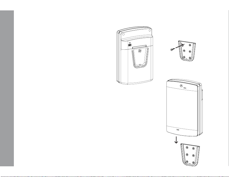
MOUNTING CLIP
Remove the BOLT LOCK, align the positive
half of the mounting clip with the screw hole,
reinsert the BOLT LOCK, and screw until tight.
Mount the negative half of the mounting
MOUNTING
clip in a desired area using six fasteners
appropriate for the wall material and
thickness.
Slide the device, with the positive half of
the mounting clip facing the wall, into the
negative half until the unit clicks into place.
20

CONTROLS INTERFACE
The CONTROLS INTERFACE is comprised
of five buttons and an LCD Display.
Escape
Up
Enter
Down
LCD
Display
Light Pipe
CONTROLS INTERFACE
Speaker
Wake Up
Call
Button
Faceplate
Microphone
Control Buttons
21

LCD DISPLAY
The CB300-D is equipped with a 2-line by 16 character LCD display. Various system information
will be shown on the display depending on the current mode of operation (normal status screen,
play/record message, channel selection, etc.).
INITIAL POWER-UP LCD SCREEN
LCD DISPLAY
The CB300-D will power-up in a mode to communicate with the PC (for configuration information
and message recording).
22

LCD DISPLAY CONT.
STATUS LCD SCREEN
If there are no active recordings, or database changes, the normal status screen will be shown
on the LCD display. These screens will toggle continuously:
LCD DISPLAY
VER: cb300d2.10
DLR: OK
CHAN No: 1
PROF ID: 0000
This status screen will show the software
version and the DLR Modem module status
(OK/FAIL).
This status screen will show the current
setting for the Channel setting and the DLR
Profile ID (the Channel and Profile ID must
match on the receiving radio).
LCD POWER
To conserver battery power, the LCD display power is controlled by the CB300-D software. Upon
system wake-up, the LCD will remain in a power-down state. Pressing any LCD menu control
button will power-up the LCD. The LCD will remain in a power-up state until the next sleep cycle.
Upon wakeup, the LCD is always disabled to conserver battery power. Press any LCD menu
control button to power-up the LCD display.
23

DEVICE WAKEUP
The following buttons will “wake-up” the
device:
ESC Button
Wake Up Button
Call Button
LCD WAKEUP
The following buttons will “wake-up” the
LCD:
DEVICE & LCD WAKEUP
ESC Button
When the or Call Button is pressed, the
LCD is still disabled until any LCD Control
Button is pressed.
24
To program new messages, it is
recommended to use the button to
wake-up the CB300-D system to prevent an
outgoing broadcast over the radio system.
The CB300-D system will support up to 6
messages of 10 seconds each. The system
expects the following message order:
Message 1: Local Message (Message played
back on local speaker)
Message 2: Radio Message (Broadcast when
the Call Button is pressed)
Message 3: “Low Battery” radio broadcast
message.

SCROLLING MENU
There are several menu selections available
in the CB300-D Interface. Press the or
buttons to scroll through the various menus,
and press the ENTER button to select the
menu item. The button will typically back
up one menu level, or may exit to the status
menu (depending of the function active when
the button is pressed). The button will
exit a menu without making any changes.
NOTE: Italicized menu selections are
hidden by default. To activate Hidden
Menus, use the or buttons to scroll
to SOFTWARE VERSION. Press ENTER
to view the software version, and then
press within six seconds. The Hidden
Menus are now activated.
SCROLLING MENU
Radio Channel
Message Record
Message Playback
Volume Adjust
LCD Contrast
Software Version
Set Profile ID
Call Cycles
Cycle Delay
Channel Ready Dly
Set LED Pattern
Enable DLR Communication
Set Defaults
25

SELECTING A CHANNEL
The radio channel is used for all RF broadcasts by the CB300-D. The CB300-D and the radio
receiver frequencies must match or the broadcast will not be received. The channel selection
numbers correspond to the channel selection of 900 MHz digital radios by Motorola.
NOTE: The DLR modem must detect a DLR receiver or the unit will not transmit.
Radio Channel?
Old: 1
SELECTING A CHANNEL
New: 1
“Old” refers to the current selected channel.
In this example, the number “1” refers to
Channel 1 of the 900 MHz digital radio.
Old: 1
**Chan Updated
26
Press the or button until the Radio
Channel? menu is shown. Press the ENTER
button to begin the next step.
Press the or arrow buttons to select a
new channel. The line “New” will display the
new channel selection.
Press-and-Hold the or button for faster
increments.
Press ENTER to select the new channel, or
to exit without any changes.
After pressing ENTER, the new channel is
selected.

MESSAGE RECORDING
Msg Record?
Press the or button until the Msg
Record? menu is shown. Press the ENTER
button to begin the next step.
MESSAGE RECORDING
Select Message?
Local Message
Hold ENTER Btn
To Record Msg
NOTE: See page 23 for the default list and
functions of recorded messages.
Press the or button until the desired
message is shown on the display.
When ready, Press-and-Hold the ENTER
button to begin recording. All sounds picked
up by the microphone will become part of
the message. Make sure you are in a quiet
environment.
Recording will continue while the ENTER
button is held down. A counter will increment
to display the elapsed time of the message
(10 seconds maximum message length).
27

MESSAGE RECORDING CONT.
-MSG LEN >10sec
Local Message
**Auto Playback
Local Message
MESSAGE RECORDING
-Playback ActLocal Message
28
NOTE: If the recording is longer than 10
seconds, the following message is shown. If
this message is shown, release the ENTER
button, shorten the message and record again.
When the ENTER button is released,
recording will end and the new message will
begin auto playback on the local speaker.
After playback is complete, the system will
loop back to the “Select Message” menu
to allow recording of additional messages.
Press to exit the recording menu.

MESSAGE PLAYBACK
Refer to the steps listed below to playback a local message using the local speaker.
NOTE: No radio broadcast will occur during message playback, only the local speaker will
become active).
MESSAGE PLAYBACK
Msg Playback?
Select Message?
Local Message
-Playback ActLocal Message
Press the or button until the Msg
Playback? menu is shown. Press the ENTER
button to begin the next step.
Press the or button until the desired
message number is shown on the display.
Press the ENTER button to begin playback
of the selected message to the local speaker.
When the playback is finished, the system
will loop back to the “Select Playback
Message” menu to allow playback of
additional messages. Press to exit.
29

VOLUME ADJUSTING
Refer to the steps listed below adjust the volume for the RF Broadcast volume and the local
speaker volume.
Volume Adjust?
Radio Volume?
VOLUME ADJUSTING
-Radio VolumeVol (1-63): 8
Speaker Volume?
-Speaker VolumeVol (1-63): 45
30
Press the or button until the Volume
Adjust? menu is shown. Press the ENTER
button to begin the next step.
Use the or buttons to increase/decrease
the volume setting. The volume settings take
place immediately. Press to exit.

LCD CONTRAST
Refer to the steps listed below to adjust the contrast on the LCD display. The LCD contrast is
set for a system with fresh batteries. As the batteries discharge over time, the LCD display may
need the contrast changed to improve the appearance of characters on the display.
LCD CONTRAST
LCD Contrast?
-LCD Contrast(0-15): 0
Press the or button until the LCD
Contrast? menu is shown. Press the ENTER
button to begin the next step.
Use the or buttons to increase/
decrease the LCD contrast. The contrast
setting will take place immediately with each
press of the or button. Press to exit.
31

SOFTWARE VERSION
There are several CB300-D software versions in service. Many of the software versions are
dependent upon a specific hardware version for compatibility. The table shown below will list
the CB300-D software version compatibility.
SOFTWARE VERSIONS
cb300d2.10
CPU
PIC18F66K22
PCB VER
A180421
VISUAL BASIC VERSION
(cb300d_v101)
SOFTWARE VERSION
CAUTION: Software versions are paired to a specific PCB hardware version and CPU number.
Loading an incompatible software version into the CB300-D hardware can cause unstable
operation of the CB300-D system.
32

SETTING PROFILE ID
The profile ID is typically set to create a private communications channel between the DLR
modem and the receiving radio. The default profile ID is set = 0000, and can be changed to any
number from 0000-9999. Both the DLR modem and the receiving radio must have identical profile
ID’s and set for the same channel to receive the radio broadcast.
EXAMPLE: Write a new Profile ID = 3692
Set Prole ID?
DIG: *
New: 0002
Press the or button until the Set Profile
ID? menu is shown. Press the ENTER button
to begin the next step.
The Profile ID is changed one digit at a time
(starting with digit ONE). Use the or
arrow button to change the digit, and press
ENTER to save the value and select the next
digit. Press to exit without any changes.
NOTE: An asterisk “*” will appear above
the digit enabled for modification.
SETTING PROFILE ID
33

SETTING PROFILE ID CONT.
DIG: *
New: 0092
DIG: *
New: 0692
SETTING PROFILE ID
DIG: *
New: 3692
DIGIT: THOUSAND
**ID Updated
34
Change the TEN’s Digit. Use the or
button to change the digit, and press ENTER
to save the value and select the next digit.
Press to exit without any changes.
Change the HUNDRED’s Digit. Use the or
button to change the digit, and press
ENTER to save the value and select the next
digit. Press to exit without any changes.
Change the THOUSAND’s Digit. Use the
or button to change the digit, and press
ENTER to save the value and select the next
digit. Press to exit without any changes.
The new Profile ID is saved and will update
the DLR modem with the new value.

CALL CYCLES
The total Call Cycles refer to the repeating RF broadcasts that will occur when the call button (or
aux) button is activated. The system will automatically clear an active call when the Total Call
Cycle value is reached. System Default: 2 cycles
CALL CYCLES
Call Cycles?
Old: 2 cycles
New: 2 cycles
Press the or button until the Call
Cycles? menu is shown. Press the ENTER
button to begin the next step.
Use the or buttons to increase/decrease the Call Cycle selection. The range is
1-30 cycles.
Press-and-Hold the or button for faster
increments.
Press ENTER to select the new Call Cycle, or
to exit without any changes.
NOTE: Special Menus must be enabled to view this selection.
35

CYCLE DELAY
The Cycle Delay refers to the delay (in seconds) between repeating RF broadcasts that occur
when the call button (or aux) button is active. System Default: 45 seconds
Cycle Delay?
CYCLE DELAY
Old: 45 seconds
New: 45 seconds
NOTE: Hidden Menus must be enabled to view this selection.
36
Press the or button until the Cycle
Delay? menu is shown. Press the ENTER
button to begin the next step.
Use the or buttons to increase/decrease the Cycle Delay selection. The range
is 10-180 seconds.
Press-and-Hold the or button for faster
increments.
Press ENTER to select the new Cycle Delay,
or to exit without any changes.

CHANNEL READY DELAY
The Motorola digital radio system will not broadcast while the radio channel is in use by others,
or if a mating digital receiver is not found (with an identical Channel No and Profile ID). The DLR
modem module will provide a “ready to transmit” signal if a mating digital radio is found, and if
the channel is not busy. To conserve battery power, the RF Module is powered down until needed
for a radio broadcast. After RF Module power-up, the system will verify the radio channel is clear
and a mating digital radio is available before message broadcast will occur. If a mating receiver
is not detected or a busy channel is detected, the system will attempt re-connection based Chan
Ready Delay value (configured using the LCD menu, “Chan Ready Delay? shown below).
Chan Ready Dly?
Press the or button until the Chan
Ready Dly? menu is shown. Press the ENTER
button to begin the next step.
CHANNEL READY DELAY
Old = 20 Sec
New = 20 Sec
Use the or buttons to cycle through the
Chan Ready Delay selections (8-120 seconds).
Press ENTER to select the new value, or
to exit without any changes. Default is
20-seconds.
In the example above, the Channel Ready Delay is set = 20 Seconds. If the Channel Ready signal
is not received, the system will re-try for a “Ready” channel every 4-seconds until a “Ready”
channel is detected, or until the 20-second Channel Ready Delay timer expires.
37

SET LED PATTERN
The CB300-D will support two LED patterns: All ON or Logo Only. The “All ON” selection is not
recommended due to the battery powered application. (To preserve battery life, the “All On”
selection is not recommended.)
Set LED Patt?
SET LED PATTERN
Old: Logo Only
New: Logo Only
AVAILABLE PATTERN SELECTIONS
ALL On: All 4-LED’s will turn ON when the
Call is active.
Logo Only: The front Logo LED will turn ON
with the Call is active. All other LED;’s will
remain OFF. This pattern is the most energy
efficient for battery power.
38
Press the or button until the Set LED
Patt? menu is shown. Press the ENTER
button to begin the next step.
Use the or Color selection (All On, Logo
Only). Press ENTER to select the new value or
to exit without any changes.

SET DEFAULTS
This menu selection will reset the system to factory default values.
SET DEFAULTS
Set Defaults?
Are You Sure?
ENTER=Y ESC=N
NOTE: Setting factory defaults will modify
several system values that can prevent RF
broadcast connections to external radios.
Verify the external radio setting are correct on
the CB300-D after setting the default values.
Press the or button until the Set
Defaults? menu is shown. Press the ENTER
button to begin the next step.
Press the ENTER button to set all values
to the factory default settings or any other
button to exit without any changes.
SYSTEM DEFAULT SETTINGS
Channel: 1
ISD Volume: 1
LED Pattern: 2 (Logo Only)
RF Broadcast Volume: 30
Local Speaker Volume: 10
Total Call Cycles: 2
Call Cycle Delay: 45 (45-seconds)
Channel Ready Delay: 20 (20-seconds)
DLR Modem Profile ID: 0000
39

NOTES
40

NOTES
41

cb300-d manual
CB300-D Manual
Printed in USA
08272018D
42
 Loading...