

Motorola 89FT5837 Users manual

ATS2500
book Page 1 Monday, December 18, 2000 7:39 PM
.
CONTENTS
Radio Overview . . . . . . . . . . . . . . . . . . . . 4
Operation and Control Functions . . . . . . . . 5
Radio Controls . . . . . . . . . . . . . . . . . . . 5
Programmable Buttons . . . . . . . . . . . . . 7
Keypad Keys (for Model II radios only) . 8
Menu Keys (for Model II radios only) . . 9
Selecting a Feature. . . . . . . . . . . . . . . . 9
Menu Display . . . . . . . . . . . . . . . . . . . 10
LCD Screen and Icons . . . . . . . . . . . . 10
Alert Tone Indications . . . . . . . . . . . . . 11
Getting Started . . . . . . . . . . . . . . . . . . . . 13
Battery Information. . . . . . . . . . . . . . . . . . 13
Battery Care and Tips . . . . . . . . . . . . . 13
Recycling or Disposal of Batteries . . . 14
Charging the Battery . . . . . . . . . . . . . . 14
Accessory Information . . . . . . . . . . . . . . . 15
Attaching the Battery. . . . . . . . . . . . . . 15
Removing the Battery . . . . . . . . . . . . . 15
Attaching the Antenna. . . . . . . . . . . . . 16
Removing the Antenna . . . . . . . . . . . . 16
Attaching the Belt Clip. . . . . . . . . . . . . 17
Removing the Belt Clip . . . . . . . . . . . . 17
Attaching the Dust Cover . . . . . . . . . . 18
Radio Operation . . . . . . . . . . . . . . . . . . . .19
Turning The Radio On or Off . . . . . . . .19
Adjusting the RadioÕs Volume. . . . . . . .19
Radio Self Test . . . . . . . . . . . . . . . . . . .19
Basic Radio Calls . . . . . . . . . . . . . . . . . .20
Selecting a Zone and Mode. . . . . . . . . . . .20
Selecting a Zone
(for Model II radios only). . . . . . . . . . . .20
Selecting a Mode . . . . . . . . . . . . . . . . . 20
Receiving a Call. . . . . . . . . . . . . . . . . . . . .21
Making a Call. . . . . . . . . . . . . . . . . . . . . . .21
Conventional Modes. . . . . . . . . . . . . . . 21
Trunked Modes. . . . . . . . . . . . . . . . . . .21
Low-Battery Alert . . . . . . . . . . . . . . . . .22
Coded Squelch Operation . . . . . . . . . . 22
Variable RF Power Level
(Selected Models Only) . . . . . . . . . . . .22
Failsoft Operation
(Trunked Systems Only) . . . . . . . . . . . . . .22
Muting the Keypad Tones
(for keypad Radios only) . . . . . . . . . . . . . .23
Trunked Features . . . . . . . . . . . . . . . . . .24
Viewing Your RadioÕs ID Number . . . . . . .24
Enhanced Private Call Operation . . . . . . .24
CONTENTS
1

ATS2500
book Page 2 Monday, December 18, 2000 7:39 PM
.
Answering a Private Call. . . . . . . . . . . 24
Making a Private Call . . . . . . . . . . . . . 25
Leaving a Call Alert Page . . . . . . . . . . 28
Call Alert Operation . . . . . . . . . . . . . . . . . 28
Answering a Call Alert Page with a Group
Call . . . . . . . . . . . . . . . . . . . . . . . . . . . 28
CONTENTS
Making a Call Alert . . . . . . . . . . . . . . . 29
Automatic Multiple Site Selection (AMSS) 31
Viewing the Current Site . . . . . . . . . . . 31
Forcing a Site Change . . . . . . . . . . . . 32
Locking and Unlocking a Site . . . . . . . 32
Conventional Features . . . . . . . . . . . . . 33
Repeat/Direct . . . . . . . . . . . . . . . . . . . . . . 33
Smart PTT . . . . . . . . . . . . . . . . . . . . . . . . 33
Scan. . . . . . . . . . . . . . . . . . . . . . . . . . . . . 35
Scan Operation . . . . . . . . . . . . . . . . . . . . 35
Turning Scan On or OFF with the Keypad
(for Keypad radios only) . . . . . . . . . . . 35
Deleting Nuisance Modes . . . . . . . . . . 36
Viewing a Scan List
(for keypad radios only) . . . . . . . . . . . 36
Programming a Scan List
(for keypad radios only) . . . . . . . . . . . 37
Scan Modes . . . . . . . . . . . . . . . . . . . . 38
Programming the Radio . . . . . . . . . . . . .39
Programming the
Telephone List Numbers . . . . . . . . . . .39
Programming the Call List . . . . . . . . . .40
Telephone Operation. . . . . . . . . . . . . . . .42
Answering a Telephone Call. . . . . . . . .42
Making a Telephone Call
(for Model II radios only). . . . . . . . . . . .42
Special Features . . . . . . . . . . . . . . . . . . .46
Emergency Operation . . . . . . . . . . . . . . . .46
Sending an Emergency Alarm . . . . . . .46
Sending a Silent Emergency Alarm . . .47
Canceling an Emergency Alarm . . . . . .47
Sending an Emergency Call . . . . . . . . .47
Ending an Emergency Call . . . . . . . . . .48
Emergency with Voice to Follow. . . . . .48
Dynamic Regrouping . . . . . . . . . . . . . . . . .48
Mode Selection. . . . . . . . . . . . . . . . . . . 48
Select Enable and Disable . . . . . . . . . .49
SmartZone Operation . . . . . . . . . . . . . . .50
Benefits of SmartZoneTM . . . . . . . . . . . . .50
Site Switching in SmartZone . . . . . . . .51
Viewing the Current Site. . . . . . . . . . . .52
2

ATS2500
book Page 3 Monday, December 18, 2000 7:39 PM
.
Forcing a Site Change . . . . . . . . . . . . 52
Locking and Unlocking a Site . . . . . . . 52
Preferred Site Selection . . . . . . . . . . . 52
Busy Override . . . . . . . . . . . . . . . . . . . 53
Site Trunking. . . . . . . . . . . . . . . . . . . . 54
Stat-Alert Features . . . . . . . . . . . . . . . . . 55
Viewing Your RadioÕs ID Number. . . . . . . 55
Stat-Alert Voice Selective Call Operation. 55
Receiving a Voice Selective Call . . . . 56
Making a Voice Selective Call. . . . . . . 56
Stat-Alert Call Alert Operation . . . . . . . . . 58
Receiving a Call Alert Page . . . . . . . . 58
Making a Call Alert . . . . . . . . . . . . . . . 59
PTT-ID . . . . . . . . . . . . . . . . . . . . . . . . . . . .60
Radio Check . . . . . . . . . . . . . . . . . . . . . . .60
Emergency Operation . . . . . . . . . . . . . . . .60
CONTENTS
3
ATS2500
book Page 4 Monday, December 18, 2000 7:39 PM
.
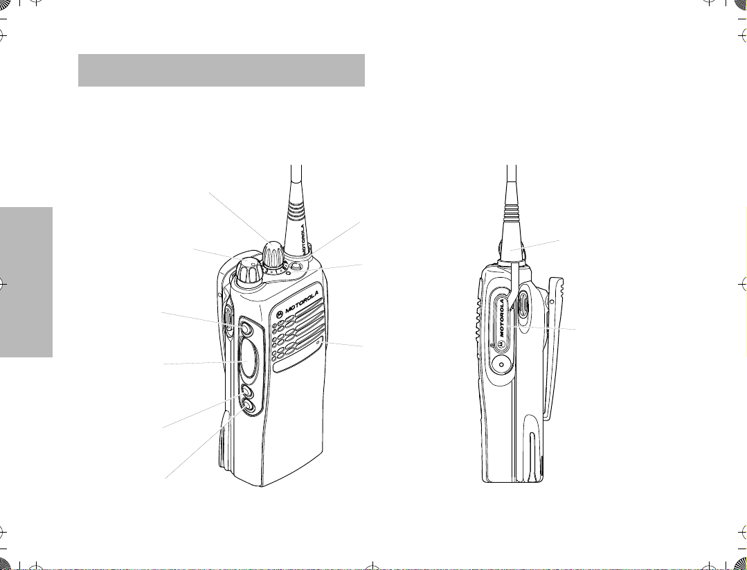
RADIO OVERVIEW
This user guide covers the operation of the ATS 2500
Portable Radio.
Please read the ÒSafety InformationÓ on pages 61 to
64 before using this radio.
1. Mode Selector Knob
2. On-Off / Volume Knob
3. Side Button 1/
Select Key
7. Top Button
10. Antenna
8. LED Indicator
RADIO OVERVIEW
4. Push to Talk (PTT)
Button
5. Side Button 2
6. Side Button 3
4
9. Microphone
Model I
11. Dust Cover
covering
Accessory
Connector

ATS2500
.
book Page 5 Monday, December 18, 2000 7:39 PM
1. Mode Selector Knob
2. On-Off / Volume Knob
7. Top Button
10. Antenna
3. Side Button 1/
Select Key
4. Push to Talk (PTT)
Button
5. Side Button 2
6. Side Button 3
OPERATION AND CONTROL FUNCTIONS
Radio Controls
Refer to the illustrations above and on the previous
page.
8. LED Indicator
9. Microphone
12. LCD Screen
13. Menu Keys
14. Keypad
Model II
1. Mode Selector Knob
Used to select the required operation mode.
2. On-Off / Volume Knob
Used to turn the radio on or off, and to adjust
the radioÕs volume.
RADIO OVERVIEW
11. Dust Cover
covering
Accessory
Connector
5
ATS2500
.
book Page 6 Monday, December 18, 2000 7:39 PM
3. Side Button 1/Select Key (programmable)
Recommended for the Monitor Button. Also
functions as the select key when programming
your radioÕs lists.
4. Push to Talk (PTT) Button
Press and hold down this button to talk, release
it to listen.
5. Side Button 2 (programmable)
6. Side Button 3 (programmable)
7. Top Button (programmable)
Recommended as Emergency button.
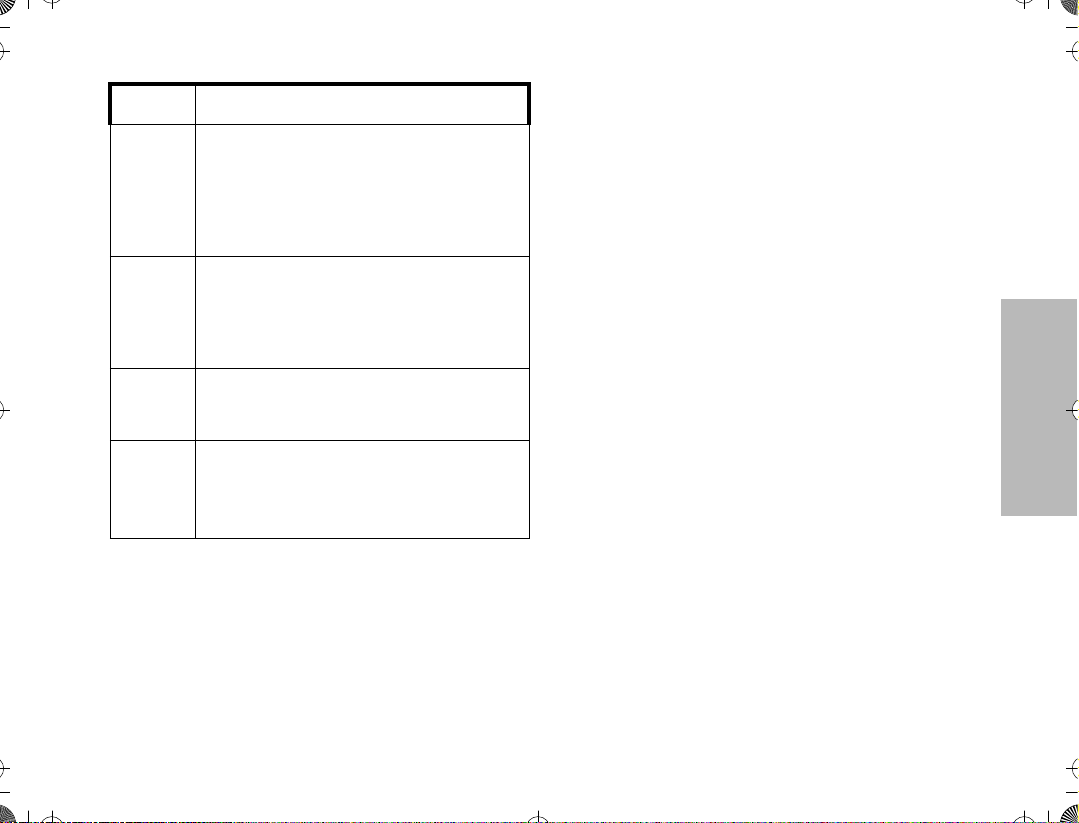
8. LED Indicator
The indicator LED on top of the radio indicates
radio operating conditions.
RADIO OVERVIEW
With PTT switch pressed (radio
transmitting)
Continuous red LED Normal transmission.
LED unlit Radio is not transmitting.
Low battery (conventional mode
Blinking red light
only; programmable from the
CPS)
With PTT switch released (radio
receiving)
Blinking red light
Blinking green light
9. Microphone
Speak clearly into the microphone when sending a message.
10. Antenna
11. Accessory Connector
Connects headsets, remote speaker/microphones and other accessories. Replace
attached dust cover when not in use.
Additionally for keypad radios (Model II), there are
12. LCD Screen
13. Menu Keys
14. Keypad
Mode busy (conventional mode
only).
Receipt of a telephone call, Private Conversation call, or Call
Alert page.
6

ATS2500
.
book Page 7 Monday, December 18, 2000 7:39 PM
Programmable Buttons
Several of your radio buttons can be programmed (by
using the Customer Programming Software Ñ CPS)
to activate the radio features.
Programmable buttons are
¥ Top button
¥ Three side buttons
Check with your dealer or Motorola representative for a
The table below shows the functions available by
short press - quickly pressing and releasing the
¥
programmable buttons, or
¥
long press - pressing and holding the
programmable buttons for a period of time
before releasing, or
¥
hold down - pressing and holding down the
programmable buttons while checking status or
making adjustments.
complete list of the functions your radioÕs
programmable buttons support.
Button Short Press Long Press Hold Down
Monitor/Permanent
Monitor
Volume Set Ñ Ñ
Scan
Nuisance Delete
Search Makes a system search.
Light Turns on/off your radioÕs backlight. Ñ Ñ
Emergency Enters Emergency mode. Leaves Emergency mode. Ñ
Call Enters or exits a Private call.
Page Enters or exits a Call Alert.
Toggles between the start/stop of the
Scan operation.
Temporarily deletes an unwanted
non-priority active scan member.
Ñ
Continually monitors the
selected channel.
Ñ Ñ
Ñ Ñ
Monitors the selected
channel for any activity.
Sounds a tone for adjusting
the radioÕs volume level.
RADIO OVERVIEW
7
ATS2500
book Page 8 Monday, December 18, 2000 7:39 PM
.
Button Short Press Long Press Hold Down
Call Response
Phone Enters or leaves Phone mode. Ñ Ñ
Respond to or exit from a Private
Call or Call Alert.
Ñ Ñ
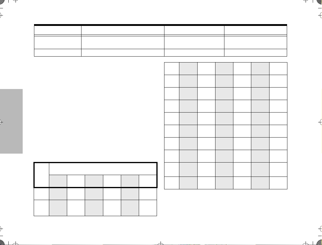
Keypad Keys (for Model II radios only)
1 2 3
4 5 6
7 8 9
* 0 #
These keys are used when dialing a phone number,
making a radio call or entering information for
programming the radioÕs lists.
The following table shows the character cycle for each
RADIO OVERVIEW
key, when entering information for programming the
radioÕs lists.
Number of Times the Key is Pressed
Key
1 2 3 4 5 6
0
1
0
Blank
1
space
8
2
3
4
5
6
7
8
9
*
#
Note: The sequence in the table above is valid
A B C 2
D E F 3
G H I 4
J K L 5
M N O 6
P Q R S 7
T U V 8
W X Y Z 9
*
# - + . / \
when entering information on a blank display.
However, when editing existing information, the
above sequence may differ. For instance, if the
9
S
¥
ATS2500.book Page 9 Monday, December 18, 2000 7:39 PM
last character entered is a Ò R Ó, pressing 7
to enter the next character, would start the character cycle at Ò
When editing existing information, pressing
1
would ALWAYS start the character cycle at
the Ò
blank space Ó and NOT at Ò 1 Ó.
Ó and NOT at Ò P Ó.
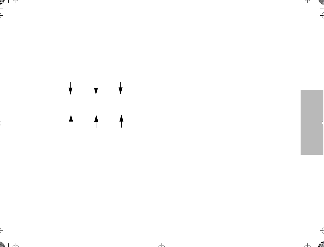
Menu Keys (for Model II radios only)
Softkey 1
Softkey 2
Softkey 3
l ; l
, . /
Left Home
Selecting a Feature
A unique feature of your radio is its use of the display
to give you quick access to many of the radioÕs
features without having to have a dedicated key for
each feature.
The names of the features (CALL, MUTE, etc.) are
shown on the display, three at a time. Selection of
features is controlled by the three keys directly below
the feature names: the left key controls the left feature,
the middle key controls the middle feature, and the
right key controls the right feature.
Right
Softkeys (l;l)
When already in Menu Mode, these keys are used to
make Menu selections.
Left and Right Arrow Keys (,/)
The left and right arrow keys are used to scroll the
display forward or backward through the radioÕs
features and lists. There is no end point to the list, so if
you continue to scroll in one direction, the display will
Òwrap aroundÓ back to the beginning of the list. If you
hold either key down, the display will scroll at a faster
rate until the key is released.
The left arrow key is also used for editing when you are
entering information manually from the keypad.
Pressing the left arrow key, when editing numeric
information (such as telephone numbers), will
backspace, and erase the display, one character at a
time. If you have erased all the digits, an additional
press of the left arrow key will return the display to the
pre-programmed list.
Pressing the left arrow key, when editing alphabetic
information (such as memberÕs names), will move the
cursor one step to the left.
HOME Key (.)
The HOME key will always return you to the home
(default) display. In most cases, this is the current
mode. In addition, if you are using a feature that
RADIO OVERVIEW

ATS2500.book Page 10 Monday, December 18, 2000 7:39 PM
requires it, pressing the HOME key will also cause
information to be saved in memory before going to the
home display. Some radio features will automatically
go to the home display when they are completed,
without having to press the HOME key, thus reducing
the number of key presses required.
Menu Display
The menu items can be displayed in normal video or in
reversed video (programmable through the CPS). All
the menu items in the examples in this manual are
shown in reversed video.
The order in which the menu items are displayed is
programmable. Thus, the order of the menu items on
your radio may differ from those shown here in this
manual. In such a situation, press the relevant softkey
to make your menu selections. All descriptions of
functions and displays after the selection are valid.
RADIO OVERVIEW
LCD Screen and Icons
Displays mode selected, channel, menu, and radio
status information. The top two screen rows show
radio status indicator symbols, explained in the
following table.
Symbol Name and Description
XPANDª Indicator
A
B
G
H
Indicates that your radio has the companding
feature activated.
Power Level Indicator
R lights up when your radio is conÞgured to
transmit in Low Power. S lights up when your
radio is conÞgured to transmit in High Power.
Carrier Squelch Indicator
Indicates when the active conventional mode is
being monitored in the carrier squelch mode;
C
ON = BEING MONITORED/
OFF = NOT BEING MONITORED.
Call Received
F
Flashes when a call or page is received.
Scan Indicator
Indicates when the radio is scanning;
ON = SCANNING/OFF =NOT SCANNING.
Priority Scan
The presence of a dot along with the scan
annunciator indicates the receiving of a priority
mode;
BLINKING DOT = PRIORITY 1
SOLID DOT = PRIORITY 2.
10
ATS2500.book Page 11 Monday, December 18, 2000 7:39 PM
Symbol Name and Description
Direct
Indicates whether you are talking directly to
J
K
M
P
another radio (talkaround), or through a
repeater;
ON = DIRECT
OFF = REPEATER.
Programming/Viewing Mode
Indicates when the radio is in the programming
or viewing mode;
ON = IN VIEWING MODE
BLINKING = IN PROGRAMMING MODE.
Signal Quality Indicator
Shows the radio signal quality. Five bars
indicates the best signal (Smart Zone Only).
Battery Level Indicator
Shows the remaining charge in your battery,
based on how many bars are displayed.
Flashing, indicates ßat battery.
Alert Tone Indications
Your radio generates a number of audible tones to
indicate radio operating conditions:
¥ Low Battery Ð A low-battery condition is indi-
cated by a high-pitched, cricket-like Òchirp-chirpÓ
when the PTT switch is released following a
transmission.
¥ Successful Power-Up Ð A short, medium-pitched
tone when the radio is Þrst turned on indicates
that the radio has passed its power-up self test
and is ready for use.
¥ Unsuccessful Power-Up Ð A short, low-pitched
tone when the radio is Þrst turned on indicates
that the radio has failed its power-up self test
and is not ready for use. Contact your service
representative for service.
¥ Transmit on Receive-Only Mode Ð If you press
the PTT switch while tuned to a Òreceive-onlyÓ
mode, you will hear a continuous, low-pitched
alert tone, indicating that no transmission is pos-
sible on this mode. This tone will continue until
the PTT switch is released.
¥ Transmit Inhibit on Busy Mode Ð If you press the
PTT switch while the mode is busy, you will hear
a continuous, low-pitched alert tone, indicating
that no transmission is possible on this mode.
This tone will continue until the PTT switch is
released.
¥ Transmit Inhibit on Flat Battery Ð If you press the
PTT while the battery is ßat, you will hear a con-
tinuous, low pitched alert tone, indicating that
transmission is impossible.
¥ Invalid Mode Ð A continuous, low-pitched tone is
heard when an invalid or unprogrammed opera-
tion is attempted on the radio.
RADIO OVERVIEW
11

ATS2500.book Page 12 Monday, December 18, 2000 7:39 PM
¥ Valid (Good) Key Press Ð A short, medium-
pitched tone when a keypad key is pressed indicates that the key press was accepted.
¥ Invalid (Bad) Key Press Ð A short, low-pitched
tone when a keypad key is pressed indicates
that the key press was rejected.
¥ Emergency Alarm Entry Ð A short, medium-
pitched tone when the emergency button is
pressed indicates that the radio has entered the
emergency mode.
¥ Emergency Alarm/Call Exit Ð A continuous,
medium-pitched tone when the radio is in the
emergency mode indicates that the radio has
exited the emergency mode.
¥ Failsoft (Trunked Systems Only) Ð A faint Òbeep-
ingÓ tone every ten seconds indicates that the
radio is operating in the failsoft mode.
¥ Time-Out Timer Warning Ð Your radioÕs time-out
RADIO OVERVIEW
timer limits the length of your transmission time.
When you are pressing the PTT switch (transmitting), a short, low-pitched warning tone will
sound four seconds before the allotted time will
expire.
¥ Time-Out Timer Timed-Out Ð If you hold down
the PTT switch longer than the time-out timerÕs
allotted time, a continuous, low-pitched tone will
sound, indicating that your transmission has
been cut off. This tone will continue until the PTT
switch is released.
¥ Phone Busy Ð A Òbah-bah-bah-bahÓ tone when
telephone interconnect is accessed indicates
that all available modes are busy and the radio is
in queue for the next available phone line.
¥ Call Alertª (Page) Received Ð A group of four
medium-pitched tones every Þve seconds indi-
cates that your radio has received a Call Alert
page.
¥ Call Alertª (Page) Sent Ð A single medium-
pitched tone (central acknowledge), followed by
a group of four medium-pitched tones indicates
that a Call Alert page sent by your radio has
been received by the target radio.
¥ Private Conversationª Call Received Ð A group
of two medium-pitched tones indicates that your
radio has received a Private Conversation call.
This sequence is repeated every Þve seconds
for approximately 20 seconds for enhanced Pri-
vate Conversation.
¥ Trunked System Busy (Trunked Systems Only) Ð
A Òbah-bah-bah-bahÓ tone when a trunked sys-
tem is accessed indicates that all available chan-
nels are busy and the radio is in queue for the
next available channel.
¥ Call Back (Trunked Systems Only) Ð A group of
three medium-pitched tones (di-di-dit) indicates
that a talkgroup is now available for your previ-
ously requested transmission.
12

ATS2500.book Page 13 Monday, December 18, 2000 7:39 PM
GETTING STARTED
BATTERY INFORMATION
Battery Care and Tips
This product is powered by a nickel-cadmium (NiCd),
nickel-metal-hydride (NiMH), or lithium-ion
rechargeable battery.
The following battery tips will help you obtain the
highest performance and longest cycle life from your
Motorola rechargeable battery.
¥ Charge your new battery overnight (14-16
hours) before using it to obtain maximum
battery capacity and performance.
¥ Charging in non-Motorola equipment may lead
to battery damage and void the battery warranty.
¥ When charging a battery that is attached to the
radio, turn the radio off to ensure a full charge.
¥ The battery should be at about 25¡C (room
temperature) whenever possible. Charging a
cold battery (below 10¡C) may result in leakage
of electrolyte and ultimately, in failure of the
battery.
¥ Charging a hot battery (above 35¡C) results in
reduced discharge capacity, affecting the
performance of the radio. Motorola rapid-rate
battery chargers contain a temperature-sensing
circuit to ensure that the battery is charged
within these temperature limits.
¥ New batteries can be stored up to two years
without signiÞcant cycle loss. Store new/unused
batteries in a cool dry area.
¥ Batteries which have been in storage should be
charged overnight.
¥ Do not return fully charged batteries to the
charger for an Òextra boostÓ. This action will
signiÞcantly reduce cycle life.
¥ Do not leave your radio and battery in the
charger when not charging. Continuous charging
will shorten battery life. (Do not use your charger
as a radio stand.)
¥ For optimum battery life and operation use only
Motorola brand chargers. They were designed to
operate as an integrated energy system.
GETTING STARTED
13
ATS2500.book Page 14 Monday, December 18, 2000 7:39 PM
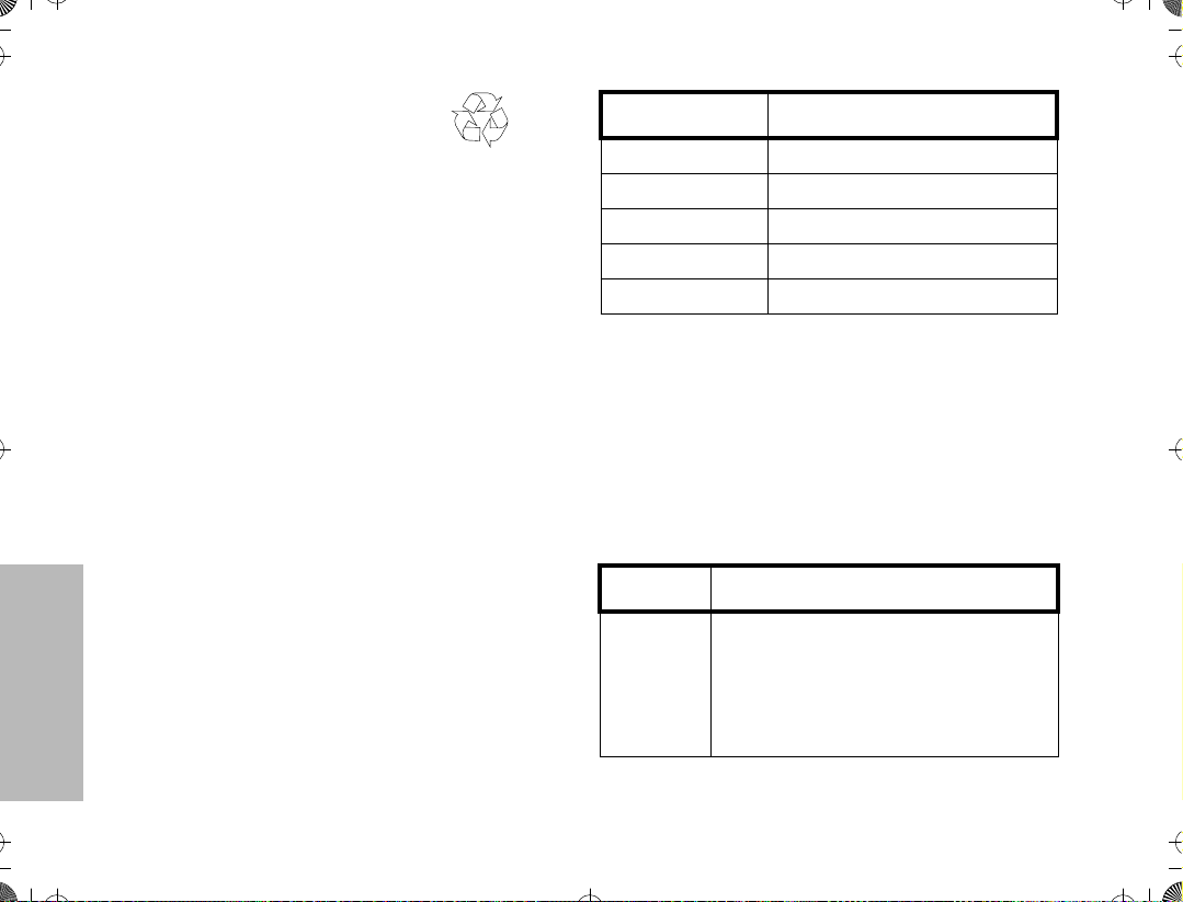
Recycling or Disposal of Batteries
NiCd
At the end of its useful life, the NiCd battery can be
recycled. However, recycling facilities may not be
available in all areas.
Motorola endorses and encourages the recycling of all
re-chargeable batteries. Contact your local Motorola
dealer for further information.
Charging the Battery
If a battery is new, or its charge level is very low,
indicated by battery level indicator showing one or no
segments, you will need to charge the battery before
you can use it in your radio.
Note:Batteries are shipped uncharged from
the factory. New batteries could
prematurely indicate full charge, charge
a new battery for 14-16 hours before
initial use.
Charger LED Status
Red Battery is charging
Green Battery is fully charged
Flashing Red * Battery is unchargeable
Flashing Yellow Charger is getting ready to charge
Flashing Green Battery is 90% charged
*
Battery is damaged. Please contact your dealer.
1. Place the radio with the battery attached, or the
battery alone, in the charger.
2. The chargerÕs LED indicates the charging
progress.
Battery chargers will charge only the Motorola
authorized batteries listed below; other batteries will
not charge.
Part No. Description
HNN9008
HNN9009
HNN9010
HNN9011
HNN9012
HNN9013
High-Capacity NiMH
Ultra-High-Capacity NiMH
Ultra-High-Capacity FM NiMH
High-Capacity FM NiCd
High-Capacity NiCd
Lithium-Ion
GETTING STARTED
FM - Factory Mutual
14

ATS2500.book Page 15 Monday, December 18, 2000 7:39 PM
ACCESSORY INFORMATION
Attaching the Battery
2
1
Slots
Removing the Battery
Battery
Latches
2
3
GETTING STARTED
1. Fit the extensions at the bottom of the
battery into the slots at the bottom of the
radioÕs body.
2. Press the top part of the battery towards the
radio until you hear a click.
1. Turn off the radio, if it is turned on.
2. Slide the battery latches, on both sides of
the battery, downwards.
3. Pull the top part of the battery away from the
radioÕs body, and remove the battery.
15

ATS2500.book Page 16 Monday, December 18, 2000 7:39 PM
Attaching the Antenna Removing the Antenna
GETTING STARTED
1. Align the threaded end of the antenna with
the radioÕs antenna connector.
2. Turn the antenna clockwise to fasten it.
16
¥ Turn the antenna counterclockwise until you can
remove it.

ATS2500.book Page 17 Monday, December 18, 2000 7:39 PM
Attaching the Belt Clip Removing the Belt Clip
Belt Clip Tab
1
2
GETTING STARTED
1. Align the grooves of the belt clip with those
of the battery.
2. Press the belt clip downwards until a click is
heard.
1. Use a key to press the belt clip tab away
from the battery.
2. Slide the belt clip upwards to remove it.
17

ATS2500.book Page 18 Monday, December 18, 2000 7:39 PM
Attaching the Dust Cover
Dust Cover
Dust Cover
Tab
Loop
GETTING STARTED
Slot for
Dust Cover Tab
1. Place the dust cover loop over the attached
antenna.
2. Slide the loop all the way down to the base
of the antenna.
3. Insert the dust cover tab into the slot above
the connector.
18
Thumbscrew
4. Tighten the thumbscrew to hold the cover in
place. DO NOT overtighten the thumbscrew.
 Loading...