


ASTRO Digital XTS 2500
Model III User Guide
68P81095C05-O
Document Creation Date: 5/2/01
Document Modification Date: 8/23/01

Preface
Before operating your radio, please review the “Safety and
General Information” section in the fr ont of this user guide. Also,
be sure to retain this publication for future reference.
Computer Software Copyrights
The Motorola products described in this manual may include
copyrighted Motorola computer programs stored in semiconductor
memories or other media. Laws in the United States and other
countries preserve for Motorola certain exclusive rights for
copyrighted computer programs, including, but not limited to, the
exclusive right to copy or reproduce in any form the copyrighted
computer program. Accordingly, any copyrighted Motorola computer
programs contained in the Motorola products described in this
manual may not be copied, reproduced, modified, reverseengineered, or distributed in any manner without the express written
permission of Motorola. Furthermore, the purchase of Motorola
products shall not be deemed to grant either directly or by implication,
estoppel, or otherwise, any license under the copyrights, patents or
patent applications of Motorola, except for the normal non-exclusive
license to use that arises by operation of law in the sale of a product.
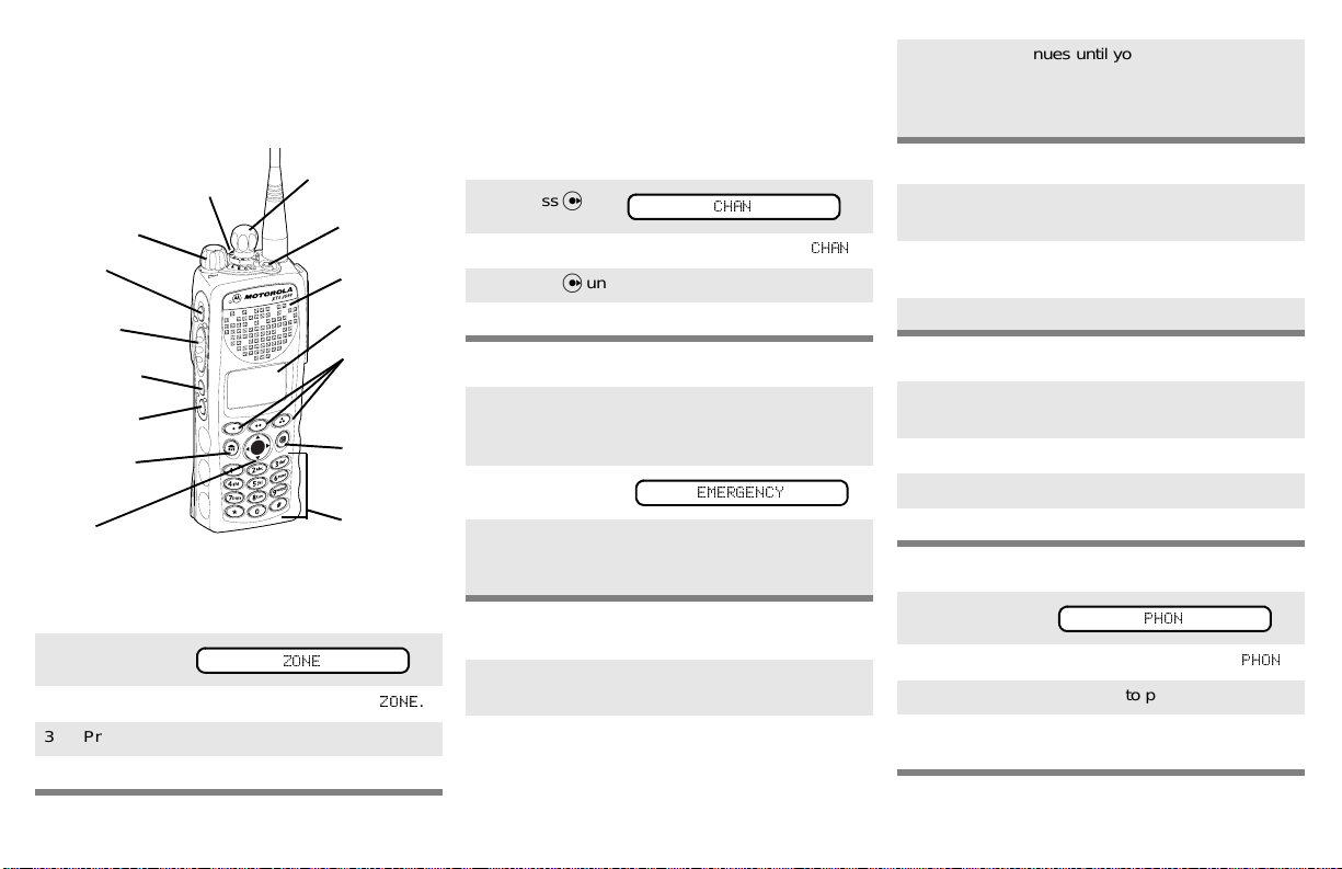
ASTRO Digital XTS 2500
16-Position
Select Knob
Speaker/Mic
Top Button
_ _ _ _ _ _ _
3-Position
Rotary Switch
_ _ _ _ _ _
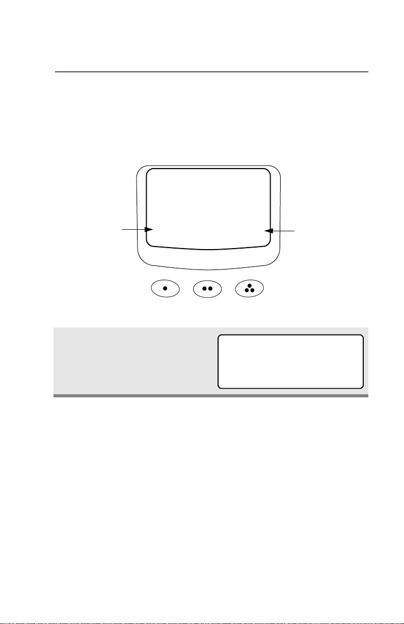
Display
Home Button
Menu Select
Buttons
Top Side
Button
_ _ _ _ _ _ _
On/Off/
Volume Knob
Side Button 1
_ _ _ _ _ _ _
Side Button 2
_ _ _ _ _ _ _
PTT Button
4-Way
Navigation
Button
Alpha Button
(for future
use)
Keypad
=21(
Model III Radio
Quick Reference Card
Select a Channel
Method 1: Using the Select Knob
After selecting the desired zone, turn the 16position Select Knob to the desired channel.
Method 2: Using the Menu
1 Press U until
2 Press D, E, or F directly below
&+$1
&+$1
3 Press U until channel you desire is shown.
4 Press h to confirm, or press PTT to transmit.
3 Alarm continues until you exit by:
• Press and hold Emergency button
OR
• Press PTT again.
Send an Emergency Call
1 Radio on and press preprogrammed
Emergency button.
.
2 Press and hold PTT button. Announce your
emergency into the microphone.
3 Release PTT to end the call.
Write your radio’s programmed features on the
dotted lines.
Select a Zone Using the Menu
1 Press U until
2 Press D, E, or F directly below
3 Press U until the zone you desire is shown.
4 Press h to confirm, or press PTT to transmit.
=21(
Send an Emergency Alarm
1 Radio on and press Emergency button. You
see red LED; you hear short, medium-pitched
tone.
2 Display shows .
(0(5*(1&<
3 When acknowledgment is received, you hear
four beeps; alarm ends; radio exits
emergency.
Send Silent Emergency Alarm
1 Radio on and press Emergency button. You
.
see no LED; you hear no tone.
2 Press PTT.
Answer a Phone Call
1 Phone-like ringing, LED flashes GREEN,
PHONE CALL and m are displayed
2 Press Call Response button.
3 Press PTT button to talk; release to listen
4Press
h to hang up.
Send a Phone Call
1Press U until
2Press D, E, or F directly below
3+21
3+21
3Press U or V to scroll to phone number.
4 Press PTT (or Quick Access button, if
programmed) to talk, release to listen.
.
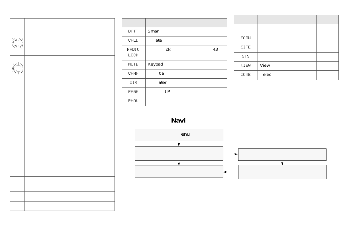
Display Status Symbols Menu Entries (Use With Menu Navigation)
HL
Power Level.
power; L = low power
Call Received. Receiving an individual
m
call
View/Program Mode. The radio is in the
p
view or program mode; On Steady = view
p
mode; Flashing = program mode
Received Signal Strength Indication
s
(RSSI).
current site (trunking only). The more
stripes in the symbol, the stronger the
signal.
Battery
b
• Conventional = Flashes when the
battery is low.
• Smart = The number of bars (0-3)
shown indicates the charge remaining
in your battery.
Power Level. H = high
Received signal strength for the
r Talkaround. You are talking directly to
another radio or through a repeater;
On = direct;
Off = repeater
Monitor (Carrier Squelch). This channel
C
is being monitored.
Scan. The radio is scanning a scan list
T
e The radio is in Emergency state
Entry Menu Selection Page
%$77
&$//
5$',2
/2&.
087(
&+$1
',5
3$*(
3+21
Smart Battery 26
Private Call 69
Radio Lock 43
Keypad Mute 45
Select a Channel 34
Repeater/Direct 77
Call Alert Page 71
Phone 65
Menu Navigation
U to find Menu Entry
D, or E, or F directly below
Menu Entry to select
h to exit
Entry Menu Selection Page
3:5
6&$1
6,7(
676
9,(:
=21(
TX Power Level 41
Scan On/Off 62
Site Lock 81
Status Call 75
Viewing a List 54
Select a Zone 33
V or U to scroll through sub-list
D, or E, or F directly below
Menu Entry to select

Contents
Safety and General Information
Transmit and Receive Procedure ......................................................1
Exposure to Radio Frequency Energy ..............................................1
Two-Way Radio Operation ............. ...... ....... ...... ....... ...... ............2
Body-Worn Operation .................................................................2
Antenna Care .............................................................................3
Approved Accessories ................................................................3
Electromagnetic Interference/Compatibility .......................................3
Facilities ...................... ............. ............. ............. ............. ............ 3
Aircraft ........................................................................................ 3
Medical Devices .........................................................................3
Pacemakers....................... ....... ...... ....... ...... ....... ...... ....... .... 3
Hearing Aids....................... ....... ....................................... .... 4
Other Medical Devices......................................................... 4
Use While Driving .............................................................................4
Operational Warnings ........................... ...... ....... ...... ....... ...... ....... ..... 5
For Vehicles With an Air Bag............................................... 5
Potentially Explosive Atmospheres...................................... 5
Blasting Caps and Blasting Areas........................................ 5
Operational Cautions .................................. ....... ...... ....... ...... ....... ..... 6
Antennas............................................................. ...... ....... .... 6
Batteries.............................................................. ...... ....... .... 6
Intrinsically Safe Radio Information ................................................... 7
FMRC Approved Equipment ....................................................... 7
Repair of FMRC Approved Products .......................................... 9
Repair.................... ....... ....................................... ...... ....... .... 9
Relabeling.......................................................................... 10
Do Not Substitute Options or Accessories......................... 10
, Motorola, ASTRO , XTS 2500 and Priv ate Conversation are trademarks of
A
Motorola, Inc.
P25 radios contain tech nology patented by Digital Voice Systems, Inc.
© 2001 by Motorola, Inc.
Commercial, Government and Industrial
Solutions Sector
8000 W. Sunrise Blvd., Ft. Lauderdale, FL 33322
Printed in U.S.A. 9/01. All Rights Reserved.
ASTRO Digital XTS 2500 Model III i
User Guide
68P81095C05-O

Contents
General Radio Operation
Notations Used in This Manual ........................................................11
XTS 2500 Model III Radio ...............................................................12
Physical Features of the Radio ........................................................13
Programmable Features ..................................................................14
Display ............................................ ................................................. 14
Backlight ..........................................................................................15
Status Symbols ................................................................................15
Menu Entry (Softkey) .......................................................................16
Menu Select Buttons .......................................................................17
Menu Selection Features ..........................................................18
Home Button (h) ............... ..............................................................19
W@P™ Button ................................................................................19
4-Way Navigation Button (o) ..........................................................19
Keypad ............................................................... ............. ............. .... 20
LED Indicators .................................................................................21
Alert Tones ......................................................................................21
Standard Accessories ......................................................................24
Battery ......................... .......................... .......................... ..........2 4
Charge the Battery ............................................................. 24
Battery Charge Status ........................................................ 24
Attach the Battery............................................................... 25
Smart Battery Condition ............................................................26
Use the Menu ..................................................................... 26
Use the Preprogrammed Smart Battery Button (Smart Battery
Only)................................................................................ 26
Antenna ....................... .......................... .......................... ..........2 7
Attach the Antenna............................................................. 27
Remove the Antenna.......................................................... 27
Belt Clip .....................................................................................28
Attach the Belt Clip............................................................. 28
Remove the Belt Clip .......................................................................28
Universal Connector Cover ..............................................................29
Remove the Connector Cover............................................ 29
Attach the Connector Cover............................................... 29
Remote Speaker Microphone Adapter ............................................30
Remove the Adapter........................................................... 30
Attach the Adapter.............................................................. 30
Radio On and Off .............................................................................32
Turn the Radio On ....................................................................32
ii

Contents
Turn the Radio Off ....................................................................32
Zones and Channels .......................................................................33
Select a Zone ...........................................................................33
Use the Menu..................................................................... 33
Use the Preprogrammed Zone Switch............................... 34
Select a Channel ...................................................................... 34
Method 1: Use the Preprogrammed Channel Selector...... 34
Method 2: Use the Menu.................................................... 35
Receive / Transmit ...........................................................................36
Without Using the Volume Set and Monitor Buttons ................36
Use Preprogrammed Volume Set Button ................................. 37
Use the Preprogrammed Monitor Button ..................................38
Conventional Mode Operation ..................................................39
Common Radio Features
Selectable Power Level ...................................................................41
Use the Menu ...........................................................................41
Use the Preprogrammed Transmit Power Level Switch .... 42
Radio Lock ......................................................................................43
Unlock Your Radio .................................................................... 43
Change Your Password ..... ...... ....................................... ....... ... 44
Mute or Unmute Keypad Tones .......................................................45
Use the Menu ...........................................................................45
Using the Preprogrammed Side Button ....................................45
Conventional Squelch Options ........................................................46
Analog Squelch ........................................................................46
Digital Squelch ..........................................................................46
PL Defeat ........................................................................................47
Time-out Timer ...... ...... ...... ....... ...... ....... ...... ....... ...... ....... ................48
Emergency ........................ .................................................... .......... 49
Send an Emergency Alarm .......................................................50
Send a Silent Emergency Alarm ...............................................51
Send an Emergency Call .......................................................... 51
Emergency Keep-Alive .............................................................53
Lists ............................. .......................... .......................... ................54
View a List ................................................................................54
Scan List Empty ........................................................................55
Edit a Call, Page, or Phone List Number ........................................55
Use the Menu ...........................................................................55
Use the Preprogrammed Number Select Button ......................57
ASTRO Digital XTS 2500 Model III iii

Contents
Edit a Call, Page, or Phone List Name .....................................59
Use the Menu ..................................................................... 59
Use the Preprogrammed Text Select Button...................... 60
Scan ................................................................................................62
Turn Scan On and Off ...............................................................62
Using the Menu .................................................................. 62
Use the Preprogrammed Scan On/Off Switch.................... 63
Individual Calls ................................................................................64
Telephone Calls ........................................................................64
Answer a Phone Call ................................................................64
Use the Preprogrammed Call Response Button ................ 64
Use the Menu ..................................................................... 65
Use the Keypad.................................................................. 66
Phone Call Display and Alert Prompts ......................................67
Enhanced Private-Conversation Calls
(Trunked Channels Only) .......................................................68
Answer a Private Call ......................................................... 68
Use the Menu ..................................................................... 69
Use the Keypad.................................................................. 70
Call Alert Paging .......................................................................71
Answer a Call Alert Page.................................................... 71
Make a Call Alert ......... ...... ....... ...... ....... ...... ....... .......................7 2
Use the Menu ..................................................................... 72
Use the Keypad.................................................................. 73
Conventional Talkgroup Calls (Conventional Operation Only) .........74
Select Talkgroup .......................................................................74
Status Calls (Trunked Radios Only) .................................................75
Send a Status Call ....................................................................75
Use the Menu ..................................................................... 75
Send a Status Call ....................................................................76
Use the Preprogrammed Status Button............................. 76
Repeater or Direct Operation ..........................................................77
Select Repeater or Direct Operation .........................................77
Use the Menu ..................................................................... 77
Use the Preprogrammed Repeater/Direct Switch .............. 78
Special Radio Features
PTT ID .............................................................................................79
Receive .....................................................................................79
Transmit ....................................................................................79
iv

Contents
View Your Radio’s ID Number ..................................................79
Use the Menu..................................................................... 79
Use the Preprogrammed Call or Page Button.................... 79
Trunking System Controls ...............................................................80
Failsoft ...................................................................... ................ 80
Out-of-Range ..................... ............................................. .......... 80
Site Lock ...................................................................................81
Lock or Unlock a Site ......................................................... 81
Site Trunking ............................................................................82
Site View and Change .............................................................. 82
View the Current Site ......................................................... 82
Change the Current Site ........................................... ......... 82
Real Time Clock ..............................................................................84
Program Time and Date ...........................................................84
Helpful Tips
Radio Care ......................................................................................87
Cleaning ................................................................................... 87
Handling ................................................................................... 87
Service ..... ....................................................................... ................ 88
Battery ............ ............. ............. ............. ............. ............. ...... .......... 89
Battery Life ...............................................................................89
Charging the Battery ................................................................. 89
Battery Charge Status........................................................ 89
Battery Recycling and Disposal ................................................ 90
Antenna ....................... .......................... .......................... ................91
Radio Operating Frequencies ................................................... 91
Accessories
Antennas ..................... .................................................... ................ 93
Audio .............................................. ................................................. 93
Headsets .................................................................................. 93
Remote Speaker Microphones ................................. ...... ....... ... 93
Batteries ......... ............................................. ....................................94
Belt Clips .........................................................................................95
Body-Worn ...................................................................................... 95
Chargers ......................................................................................... 95
Enhanced and Multi-Unit Line Cords ........................................ 96
ASTRO Digital XTS 2500 Model III v

Contents
Glossary
Commercial Warranty
Index
vi

Safety and General Information
IMPORTANT INFORMATION ON SAFE AND EFFICIENT
OPERATION
READ THIS INFORMATION BEFORE USING YOUR MOTOROLA
TWO-WAY RADIO
The information provided in this document supersedes the general
safety information contained in user guides published prior to June
2001. For information regarding radio use in a hazardous atmosphere
please refer to the Factory Mutual (FM) Approval Manual Supplement
or Instruction Card, which is included with radio models that offer this
capability.
Transmit and Receive Procedure
Your two-way radio contains a transmitter and a receiver. To
transmit (talk) you must push the Push-To-Talk button; to
receive (listen) you must release the Push-To-Talk button.
Exposure to Radio Frequency Energy
Your Motorola radio is designed to comply with the following national
and international standards and guidelines regarding exposure of
human beings to radio frequency electromagnetic energy (EME):
• United States Federal Communications Commission, Code of
Federal Regulations; 47 CFR part 2 sub-part J
• American National Standards Institute (ANSI) / Institute of
Electrical and Electronic Engineers (IEEE) C95. 1-1992
• Institute of Electrical and Electronic Engineers (IEEE) C95.1-1999
Edition
• National Council on Radiation Protection and Measurements
(NCRP) of the United States, Report 86, 1986
• International Commission on Non-Ionizing Radiation Protection
(ICNIRP) 1998
• Ministry of Health (Canada) Safety Code 6. Limits of Human
Exposure to Radiofrequency Electromagnetic Fields in the
Frequency Range from 3 kHz to 300 GHz, 1999
ASTRO Digital XTS 2500 Model III 1

Safety and General Information
I
• Australian Communications Authority Radiocommunications
(Electromagnetic Radiation - Human Exposure) Standard 1999
(applicable to wireless phones only)
• ANATEL, Brasil Regulatory Authority, Resolution 256 (April 11,
2001) “additio na l req ui rem en ts for SMR, cellular and PC S p rod uct
certification.”
T o assure optimal radio performance and make sure human exposure
to radio frequency electromagnetic energy (EME) is within the
guidelines set forth in the above standards, always adhere to the
following procedures:
Two-Way Radio Operation
When using your radio as a traditional two-way radio,
hold the radio in a vertical position with the
microphone 1 to 2 inches (2.5 to 5.0 cm) away
MAN WITH RAD
from your lips.
Body-Worn Operation
To maintain compliance with FCC RF exposure guidelines, if you
wear a radio on your body when transmitting, always place the radio
in a Motorola approved clip, holder, holster, case, or body
harness for this product. Use of non-Motorola-approved
accessories may exceed FCC RF exposure guidelines. If you do not
use a Motorola approved body-worn accessory and are not
using the radio in the intended use positions along side of the
head in the phone mode or in front of the face in the two-way
radio mode, then ensure the antenna and radio is kept the
following minimum distances from the body when transmitting:
• Phone or Two-way radio mode: one inch (2.5 centimeters)
• Data operation using any data feature with or without an
accessory cable: one inch (2.5 centimeters)
2

Safety and General Information
Antenna Care
Use only the supplied or an approved replacement antenna.
Unauthorized antennas, modifications, or attachments could damage
the radio and may violate FCC regulations.
DO NOT hold the antenna when the radio is “IN USE.” Holding the
antenna affects call quality and may cause the radio to operate at a
higher power level than needed.
Approved Accessories
For a list of approved Motorola accessories look in the appendix or
accessory section of this manual.
Electromagnetic Interference/Compatibility
Note: Nearly every electronic device is susceptible to
electromagnetic interference (EMI) if inadequately shielded,
designed, or otherwise configured for electromagnetic
compatibility.
Facilities
To avoid electromagnetic interference and/or compatibility conflicts,
turn off your radio in any facility where posted notices instruct you to
do so. Hospitals or health care facilities may be using equipment that
is sensitive to external RF energy.
Aircraft
When instructed to do so, turn off your radio when on board an
aircraft. Any use of a radio must be in accordance with applicable
regulations per airline crew instructions.
Medical Devices
Pacemakers
The Health Industry Manufacturers Association recommends that a
minimum separation of 6 inches (15 centimeters) be maintained
between a handheld wireless radio and a pacemaker. These
ASTRO Digital XTS 2500 Model III 3

Safety and General Information
recommendations are consistent with those of the U.S. Food and
Drug Administration.
Persons with pacemakers should:
• ALWAYS keep the radio more than 6 inches (15 centimeters)
from their pacemaker when the radio is turned ON.
• not carry the radio in the breast pocket.
• use the ear opposite the pacemaker to minimize the potential
for interference.
• turn the radio OFF immediately if you have any reason to
suspect that interference is taking place.
Hearing Aids
Some digital wireless radios may interfere with some hearing aids. In
the event of such interference, you may want to consult your hearing
aid manufacturer to discuss alternatives.
Other Medical Devices
If you use any other personal medical device, consult the
manufacturer of your device to determine if it is adequately shielded
from RF energy. Your physician may be able to assist you in obtaining
this information.
Use While Driving
Check the laws and regulations on the use of radios in the area
where you drive. Always obey them.
When using your radio while driving, please:
• Give full attention to driving and to the road.
• Use hands-free operation, if available.
• Pull off the road and park before making or answering a call if
driving conditions so require.
4

Operational Warnings
!
!
For Vehicles With an Air Bag
Do not place a portable radio in the area over an air
W A R N I N G
bag or in the air bag deployment area. Air bags
inflate with great force. If a port able radio is placed
in the air bag deployment area and the air bag
inflates, the radio may be propelled with great
force and cause serious injury to occupants of the
vehicle.
Potentially Explosive Atmospheres
Tu rn off your radio prior to entering any area with a
potentially explosive atmosphere, unless it is a
radio type especially qualified for use in such
areas as “Intrinsically Safe” (for example, Factory
Mutual, CSA, UL, or CENELEC). Do not remove,
install, or charge batteries in such areas. Sparks in
a potentially explosive atmosphere can cause an
explosion or fire resulting in bodily injury or even
death.
Safety and General Information
Note: The areas with potentially explosive
atmospheres referred to above include
fueling areas such as below decks on
boats, fuel or chemical transfer or storage
facilities, areas where the air contains
chemicals or particles, such as grain, dust
or metal powders, and any other area where
you would normally be advised to turn off
your vehicle engine. Areas with potentially
explosive atmospheres are often but not
always posted.
Blasting Caps and Blasting Areas
T o avoid possible interference with blasting
operations, turn off your radio when you are near
electrical blasting caps, in a blasting area, or in
areas posted: “Turn off two-way radio.” Obey all
signs and instructions.
ASTRO Digital XTS 2500 Model III 5
Safety and General Information
!
Operational Cautions
Antennas
Do not use any portable radio that has a damaged
C a u t i o n
antenna. If a damaged antenna comes into contact
with your skin, a minor burn can result.
Batteries
All batteries can cause property damage and/or
bodily injury such as burns if a conductive
material such as jewelry, keys, or beaded chains
touches exposed terminals. The conductive
material may complete an electrical circuit (short
circuit) and become quite hot. Exercise care in
handling any charged battery, particularly when
placing it inside a pocket, purse, or other cont ainer
with metal objects.
6

Safety and General Information
Intrinsically Safe Radio Information
FMRC Approved Equipment
Anyone intending to use a radio in a location where hazardous
concentrations of flammable materials exist (hazardous
atmosphere) is advised to become familiar with the subject of
intrinsic safety and with the National Electric Code NFPA 70
(National Fire Protection Association) Article 500 (hazardous
[classified] locations).
An Approval Guide, issued by Factory Mutual Research
Corporation (FMRC), lists manufacturers and the products
approved by FMRC for use in such locations. FMRC has also
issued a voluntary approval standard for repair service (“Class
Number 3605”).
FMRC Approval labels are attached to the radio to
FM
APPROVED
MAEPF-24560-O
identify the unit as being FM Approved for specified
hazardous atmospheres. This label specifies the
hazardous Class/Division/Group along with the par t
number of the battery that must be us ed. Depend ing
on the design of the portable unit, this FM label can
be found on the back or the bottom of the radio
housing. The FM Approval mark is shown here.
ASTRO Digital XTS 2500 Model III 7

Safety and General Information
!
!
• Do not operate radio communications
equipment in a hazardous atmosphere unles s it
is a type especially qualified (for example,
W A R N I N G
FMRC Approved) for such use. An explosion or
fire may result.
• Do not operate an FMRC Approved Product in a
hazardous atmosphere if it has been physically
damaged (for example, cracked housing). An
explosio n or fire may result.
• Do not replace or charge batteries in a
hazardous atmosphere. Contact sparking may
occur while installing or removing batteries and
cause an explosion or fire.
• Do not replace or change accessories in a
hazardous atmosphere. Contact sparking may
occur while installing or removing accessories
and cause an explosion or fire.
• Do not operate an FMRC Approved Product unit
in a hazardous location with the accessory
contacts exposed. Keep the connector cover in
place when accessories are not used.
• Turn a radio off before removing or installing a
battery or accessory.
• Do not disassemble an FMRC Approved
Product unit in any way that exposes the
internal electrical circuits of the unit.
Radios must ship from the Motorola manufacturing facility with the
hazardous atmosphere capability and FM Approval labeling. Radios
will not be “upgraded” to this capability and labeled in the field.
A modification changes the unit’s hardware from its original design
configuration. Modifications can only be made by the original product
manufacturer at one of its FMRC-audited manufacturing facilities.
8
Safety and General Information
!
!
!
!
• Failure to use an FMRC Approved Product unit
with an FMRC Approved battery or FMRC
Approved accessories specifically approved for
W A R N I N G
that product may result in the dangerously
unsafe condition of an unapproved radio
combination being used in a hazardous
location.
• Unauthorized or incorrect modification of an
FMRC Approved Product unit will negate the
Approval rating of the product.
Repair of FMRC Approved Products
REP AIRS FOR MOTOROLA PRODUCTS WITH FMRC APPROVAL
ARE THE RESPONSIBILITY OF THE USER.
You should not repair or relabel any Motorola- manufactured
communication equipment bearing the FMRC Approval label (“FMRC
Approved Product”) unless you are familiar with the current FMRC
Approval standard for repairs and serv ic e (“Cl ass N umb er 3605”).
You may want to consider using a repair facility that operates under
3605 repair service approval.
• Incorrect repair or relabeling of any FMRC
Approved Product unit could adversely affect
the Approval rating of the unit.
W A R N I N G
FMRC’s Approval Standard Class Number 3605 is subject to change
at any time without notice to you, so you may want to obtain a current
copy of 3605 from FMRC. Per the December 1994 publication of
3605, some key definitions and service requirements are as follows:
Repair
A repair constitutes something done internally to the unit that would
bring it back to its original condition—Approved by FMRC. A repair
should be done in an FMRC Approved facility.
ASTRO Digital XTS 2500 Model III 9
• Use of a radio that is not intrinsically safe in a
hazardous atmosphere could result in serious
injury or death.

Safety and General Information
Items not considered as repairs are those in which an action is
performed on a unit which does not require the outer casing of the
unit to be opened in a manner which exposes the internal electrical
circuits of the unit. You do not have to be an FMRC Approved Repair
Facility to perform these actions.
Relabeling
The repair facility sh all ha ve a met hod by which t he repl acem ent o f
FMRC Approval labels are controlled to ensure tha t any relabeling is
limited to units t hat were originall y shipped from the Ma nufacturer with an
FM Approval label in place. FMRC Approval labels shall not be stocke d
by the repair facility. An FMRC Approval labe l sh all be o rdere d f rom t he
original manufacturer, as needed, to repair a specific unit. Replacement
labels may be obt ained and applied by the rep air fa cilit y, provided t here
is satisfactory evidence that t he unit bei ng rela beled was ori ginally an
FMRC Approved uni t. V erificat ion may include , but is not limi ted to: a u nit
with a damaged Ap proval label, a uni t with a defect ive housing displayin g
an Approval label, or a cust ome r in voice in dicatin g t he seri al num ber of
the unit and purchase of an FMRC App roved mode l.
Do Not Substitute Options or Accessories
The Motorola communications equipment certified by Factory Mutual is
tested as a system and consists of the FM Approved portable, FM Approved
battery , and FM Approved accessories or options, or both. This FM
Approved portable and battery combination must be strictly observed. There
must be no substitution of items, even if the substitute has been previously
Approved with a different Motorola communications equipment unit.
Approved configurations are listed in the FM Approval Guide published by
FMRC, or in the product FM Supplement. This FM Supplement is shipped
from the manufacturer with the FM Approved radio and battery combination.
The Approval Guide, or the Approval St andard Class Number 3605
document for repairs and service, can be ordered directly from Factory
Mutual Research Corporation located in Norwood, Massachusetts.
10
General Radio Operation
!
!
!
Notations Used in This Manual
You will notice the use of WARNINGS, CAUTIONS, and Notes
throughout this manual. These notations are used to emphasis that
safety hazards exist and that care must be taken or observed.
WARNING: An operational procedure, practice,
condition, etc. exists which may result in injury or
death if not carefully observed.
W A R N I N G
CAUTION: An operational procedure, practice,
condition, etc. exists which may result in damage to
the equipment if not carefully observed.
C a u t i o n
Note: A Note is an operational procedure, practice, or condition,
etc. which is essential to emphasize.
The following special notations identify certain items:
Example Description
D Buttons are shown as
representative symbols.
3+21(&$//
3+21( Menu entries are shown similar
ASTRO Digital XTS 2500 Model III 11
Information appearing in the
radio’s display is shown using
the special display font.
to the way they appear in the
radio’s display.
General Radio Operation
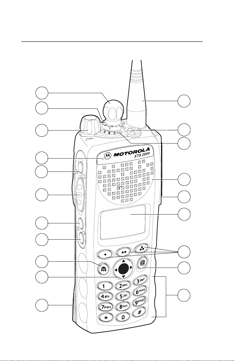
XTS 2500 Model III Radio
10
11
1
12
13
14
15
16
17
18
19
20
2
3
4
5
6
7
8
9
12

General Radio Operation
Physical Features of the Radio
Item Page Item Page
1 Antenna 27 11 3-Position Rotary
Switch
(programmable)
2 Top Button
(programmable)
3 LED 21 13 Microphone
4 Speaker 14 Top Side Button
5 Universal Connector 29 15 Push-to-Talk
6 Display 14 16 Side Button 1
7 Menu Select Buttons
(programmable)
8 Alpha Button
(for future use)
9 Keypad 20 19 4-Way Navigation
10 16-Position Select
Knob
(programmable)
12 On/Off/Volume
Control Knob
(programmable)
(PTT) Button
(programmable)
17 17 Side Button 2
(programmable)
18 Home Button 19
Button
20 Battery 24
32
19
ASTRO Digital XTS 2500 Model III 13
General Radio Operation
Programmable Features
These features are programmable by a qualified technician:
Feature Page Feature Page
Call Alert Page 71 Repeater/Direct 77
Call Response 64 Scan On/Off 62
Channel Selection 34 Site Lock/Unlock 81
Emergency 49 Site Search 82
Keypad Mute 45 Status Call 75
Monitor 38 Text Select 60
Number Select 57 Transmit Power Level 41
Phone 64 Volume Set 37
PL Defeat 47 Zone Selection 33
Private Call 68
Display
$0
7$%&'()*+,-./012
73456789:;<=
6,7(/2&.('
/2&.
The above screen example may not be identical to the display symbol
arrangement in your radio. The top two screen rows display menu
and radio status information.
14
81/.
General Radio Operation
Backlight
If poor light conditions make the display or channel numbers (around
the 16-Position Select knob) difficult to read, turn on the radio’s
backlights by pressing the Light button.
These lights will remain on for a preprogrammed time before they turn
off automatically, or you can turn them off immediately by pressing the
Light button again.
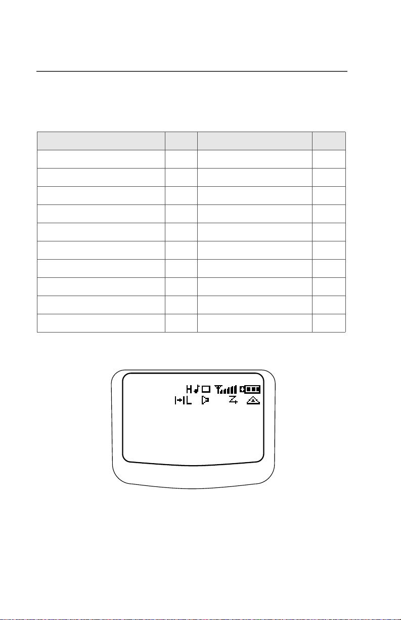
Status Symbols
The top two rows in the display contain symbols indicating the radio’s
status.
Table 1: Status Symbols
Symbol Indication Page
HL
/
2
2
4
&
Pow er Leve l. High Power “H” or Low
Power “L” is activated.
Call Received. Flashes when an
Individual Call is received.
View/Program Mode.
• View a list (steady)
• Program a list (flashing)
Received Signal Strength Indication
(RSSI). The received signal strength for
the current site. Trunked only. The more
stripes in the symbol, the stronger the
received signal.
Battery
• Conventional = Flashes when the
battery is low.
• Smart = The number of bars (0-3)
shown indicates the charge remaining
in your battery.
level reaches 10% or less.
Flashes when battery
41
64
54
82
24
ASTRO Digital XTS 2500 Model III 15

General Radio Operation
Table 1: Status Symbols
Symbol Indication Page
3
)
Talkaround.
• On = Talking directly to another radio,
not through a repeater. Conventional
operation only.
• Off = Talking through a repeater.
Monitor (Carrier Squelch). The se lected
channel is being monitored. Conventional
operation only.
Scan. The radio is scanning a scan list. 62
Emergency. The radio enters the
Emergency State.
77
38
49
Menu Entry (Softkey)
The bottom row of the display contains one to three menu entries
(also known as softkeys). The menu entries allow you to select from
one of several menus to access the radio’s features. The menu
entries are accessed using the Menu Select buttons.
16
General Radio Operation
Menu Select Buttons
The Menu Select buttons access the menu entries of features that
have been activated by a qualified radio technician. Your radio may
be programmed differently from the following example, but the display
for selecting Scan on or off might look like this:
6&$1
softkey
Example: To turn scan on
Press D.
The display shows the selected
state.
21 2))
softkey
3 Menu Select
Buttons
6&$121
21 2))
ASTRO Digital XTS 2500 Model III 17

General Radio Operation
Menu Selection Features
In most cases, pr ess U to display the following feature selections.
Feature Menu Selection Page Feature
Call Alert
Page
Call
Response
Channel
Selection
Emergency
Keypad
Mute
Number
Select
Phone
3$*( 72 Repeater/
Direct
3+21(&$//
5(&(,9('
or
35,9$7(&$//
5(&(,9('
or
3$*(5(&(,9('
&+$1 34 Site Lock/
(0(5*(1&< 49 Site
087( 45 Status
180 57 Text
3+21 65 Transmit
64
68
71
Scan On/
Off
Unlock
Search
Call
Select
Power
Level
Menu
Selection
',5 77
6&$1 62
6,7( 81
6&$1,1*
6,7(
676 75
352* 60
3:5 82
Page
82
Private Call
18
&$// 69 Zone
Selection
=21( 33

General Radio Operation
Home Button (h)
The Home button will always return you to the home (default) display.
In most cases, this is the current mode.
Some radio features require saving information in memory. Pressing
the Home button while using those features will cause information to
be saved before going to the home display.
Some features do not require you to press the Home button to go to
the home display. This reduces the required number of button
presses.
W@P™ Button
Reserved for future use.
4-Way Navigation Button (o)
This button is used to scroll through the radio’s lists or items in the
display.
ASTRO Digital XTS 2500 Model III 19
General Radio Operation
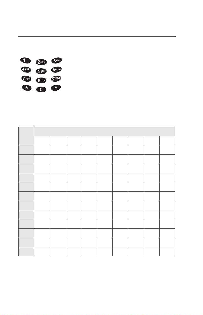
Keypad
The 3 x 4 alphanumeric keypad provides an
interface to your radio’s features.
The keypad functions in a manner similar to a
standard telephone keypad when entering
numeric digits.
When the keypad is used to edit a list, each key
can generate different characters of the
alphabet. Refer to the following table for a
complete list of characters.
Key
0
1
2
3
4
5
6
7
8
9
*
#
Number of times the key is pressed
123456789
0()<>
1&%
ABC2abc
DEF3def
GHI4ghi
JKL5j k l
MNO6mno
PQRS7pqrs
TUV8 t uv
WXYZ9wxyz
*/+-=
#.!?,;
20

General Radio Operation
LED Indicators
This LED Color: indicates:
RED (Non-flashing) Transmitting
RED (Flashing) • Channel Busy
or
• Low Battery (lights while transmitting)
GREEN Receiving Individual Call
Alert Tones
Your radio uses alert tones to inform you of radio conditions.
Table 2: Alert Tones
You hear: Tone Name Heard :
Invalid Key-Press when the wrong key is
pressed.
Radio Self-Test Failed when the radio fails the
power-up self te st .
Short,
Low-Pitched
Tone
ASTRO Digital XTS 2500 Model III 21
No ACK Received when the radio does not
receive an
acknowledgment.
Reject when an unauthorized
request is made.
Time-Out Timer Warning four seconds before time
out.

General Radio Operation
Table 2: Alert Tones (Continued)
You hear: Tone Name Heard :
Long,
Low-Pitched
Tone
A Group of
Low-Pitched
Tones (Busy
Tone)
Long,
MediumPitched Tone
Time-Out Timer Timed
after time out.
Out
Talk Prohibit/
PTT Inhibit
when the PTT button is
pressed, and
transmissions are
prevented.
Out-of-Range when the PTT button is
pressed, but the radio is
out of range of the
system.
Invalid Mode when the radio is set to
an unprogrammed
channel.
Individual Call Warning
Tone
when the radio is in
Individual Call without
any activity for more than
6 seconds.
Busy when the system is busy.
Volume Set when volume changed
on a quiet channel.
Emergency Exit upon exiting the
emergency state.
22

General Radio Operation
Table 2: Alert Tones (Continued)
You hear: Tone Name Heard :
Failsoft when the system fails.
Automatic Call Back when the voice channel
is available from the
previous request.
Talk Permit upon pr es si ng the PTT
button, it verifies the
system is accepting
transmissions.
A Group of
MediumPitched
Tones
Console
Acknowledge
when a status,
emergency alarm, or
reprogram request
acknowledgment is
received.
Received
Individual Call
when a Call Alert, or
Private Conversation Call
is received.
Call Alert Sent when a Call Alert is
received by the target
radio.
Short, HighPitched Tone
(Chirp)
Low-Battery Chirp when the battery is below
the preset threshold
value.
Fast Ringing when the system is
searching for the Private
Conversation Call target
radio.
Ringing
Enhanced Call Sent when waiting for the
Private Conversation Call
target radio to respond to
the call.
Phone Call Received when a landline phone
call is receive d.
ASTRO Digital XTS 2500 Model III 23
General Radio Operation
!
!
Standard Accessories
Battery
T o avoid a possible explosion:
• DO NOT replace the battery in any area
W A R N I N G
Charge the Battery
The Motorola-approved battery shipped with your radio is uncharged.
Prior to using a new battery, charge it for a minimum of 16 hours to
ensure optimum capacity and performanc e.
For a list of Motorola-authorized batteries available for use with your
XTS 2500 radio, see “Batteries” on page 54.
Note: When charging a battery attached to a radio, turn the radio off
to ensure a full charge.
labeled “hazardous atmosphere”.
• DO NOT discard batteries in a fire.
Battery Charger
To charge the battery, place the battery, with or without the radio, in a
Motorola-approved charger. The charger’s LED indicates the
charging progress; see your charger’s user guide. For a list of
chargers, see “Chargers” on page 55.
Battery Charge Status
If programmed by a qualified technician, you can check your battery’s
charge status by holding down the preprogrammed Battery Gauge
button. The charge status is shown by the color of the radio’s LED
indicator.
Battery Level LED Indicator
High Green
Sufficient Yellow
Low Flashing Red
Very low N one
24

Attach the Battery
1 With the radio off, fit the
three extensions at the
bottom of the battery into the
bottom slots on the radio.
2 Press the top of the battery
against the radio until it clicks
into place.
Remove the Battery
General Radio Operation
1 With the radio off, slide down
the latches on the sides of
the battery.
2 Pull the top of the battery
away from the radio.
ASTRO Digital XTS 2500 Model III 25

General Radio Operation
Smart Battery Condition
This feature lets you view the condition of your Smart Battery.
Use the Menu
1 Press U to find %$77.
2 Press D, E, or F directly
below %$77
Note: If a Smart Battery is not
powering your radio
3 Press h to exit.
Use the Pr eprogrammed Smart Battery Button (Smart Battery Only)
1 Press the Smart Battery
button.
.
%$77
&$3$&,7<
,1,7
(67&+*6
60$57%$77
'$7$127
$9$,/$%/(
&$3$&,7<
,1,7
Note: If a Smart Battery is not
powering your radio
2 Press
26
h to exit.
(67&+*6
60$57%$77
'$7$127
$9$,/$%/(

General Radio Operation
Antenna
Your radio’s operating frequency is 806 to 870 MHz. For information
regarding other available antennas, see page 91.
Attach the Antenna
With the radio off, turn the
antenna clockwise to attach it.
Remove the Antenna
With the radio off, turn the
antenna counter-clockwise to
remove it.
ASTRO Digital XTS 2500 Model III 27
General Radio Operation
Belt Clip
Attach the Belt Clip
1 Align the grooves of the belt
clip with those of the battery.
2 Press the belt clip downward
until you clear a “click.”
Remove the Belt Clip
1 Use a flat-bladed object to
press the belt clip tab away
from the battery.
2 Slide the belt clip upward to
remove it.
28

General Radio Operation
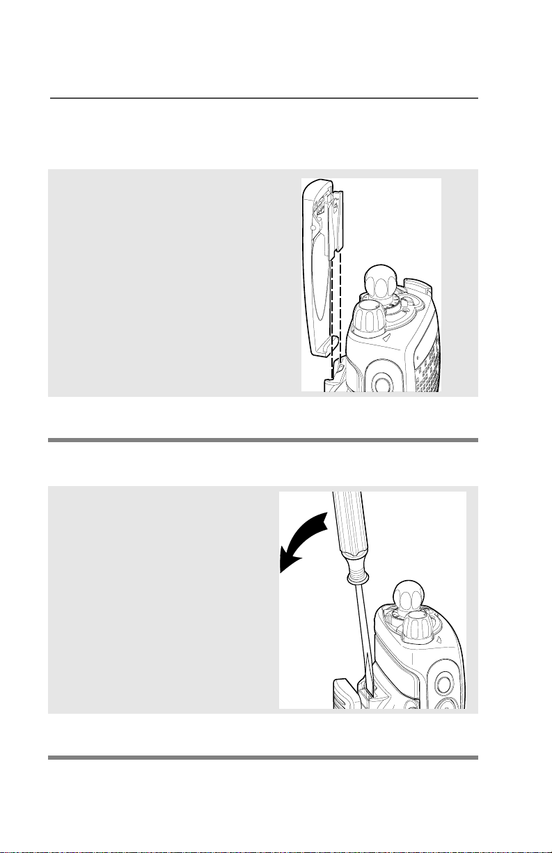
Universal Connector Cover
The universal connector cover is located on the antenna side of the
radio. It is used to connect certain accessories to the radio.
To prevent damage to the connector, shield it with the connector
cover when not in use.
Remove the Connector Cover
1 Insert a flat-blade
screwdriver into the area
between the bottom of the
cover and the slot below the
connector.
2 Hold the top of the cover with
your thumb while you pry the
bottom of the cover away
from the radio with the
screwdriver.
Attach the Connector Cover
1 Insert the hooked end of the
cover into the top of the
Top
Hooked End
Top
Slot
connector. Press downward
on the cover’s top to seat it
into the slot.
2 Press the cover’s lower tab
below the connector until it
snaps in place.
Tab
Bottom
Hooked End
Bottom
Slot
ASTRO Digital XTS 2500 Model III 29

General Radio Operation
Remote Speaker Microphone Adapter
The Remote Speaker Microphone (RSM) adapter is located on the
back of the radio, just above the battery. It must be used to connect
the RSM accessories (see page 53) to the radio.
Remove the Adapter
Lift the larger side (below the
antenna port) of the adapter
away from the radio using your
finger.
If you cannot easily remove the
adapter with your finger, use a
small, flat blade screwdriver to
pry the larger end side of the
adapter away from the radio.
Attach the Adapter
1 With the Motorola side of the
adapter facing out, snap the
smaller end of the adapter
into place in the shroud
indent, below the On/Off
Volume Control Knob.
30

2 Snap the larger end of the
adapter into place in the
shroud indent, below the
antenna port.
General Radio Operation
ASTRO Digital XTS 2500 Model III 31

General Radio Operation
Radio On and Off
Turn the Radio On
1 Turn the On/Off/Volume
Control knob clockwise.
• If the power-up test is
successful, you will see
6HOI7HVW
• If the power-up test is
unsuccessful, you will see
(5525;;<<. (;;<< is an
alphanumeric code.) Turn off
the radio, check the battery,
and turn the radio on again. If
the radio continues to fail the
power-up test, record the
(5525;;<< code and
contact a qualified service
technician.
6HOI7HVW
(5525;;<<
Turn the Radio Off
Turn the On/Off/Volume Control
knob counterclockwise until it
clicks.
32

General Radio Operation
Zones and Channels
A zone is a grouping of channels. A channel is a group of radio
characteristics, such as transmit/receive frequency pairs.
Before you use your radio to receive or send messages, you should
select the zone and channel.
Select a Zone
Use the Menu
1 Press U to find =21(.
=21(
2 Press D, E, or F
directly below =21(.
The current zone (in this
case, 32/) flashes and the
channel name (',631:),
does not flash.
32/',631:
3 Press U to find the zone you
want. For example, ),5(.
4 Press h to confirm the
displayed zone and channel.
OR
Press the PTT button to
transmit on the displayed
zone/channel.)
ASTRO Digital XTS 2500 Model III 33
),5( ',631:
),5( ',631:

General Radio Operation
Use the Preprogrammed Zone Switch
1 If a control on your radio has
been preprogrammed as the
Zone Switch, move the
Zone Switch to the position
for the zone you want.
Note: If the zone you selected
is unprogrammed, repeat
step 1.
2 Press h to confirm the
displayed zone and channel.
),5( ',631:
81352*5$00('
Select a Channel
Consult an authorized service technician for the right choice between
the following methods.
Method 1: Use the Preprogrammed Channel Selector
After the zone you want is
displayed, turn the
preprogrammed Channel
Selector switch to the desired
channel.
34

Method 2: Use the Menu
1 Press U to find &+$1.
2 Press D, E, or F
directly below &+$1.
The display shows the
current channel name (in
this case, ',631:) flashing
and the zone (32/), not
flashing.
3 Press U to find the channel
name you want.
OR
Use the keypad to enter the
channel number.
If the channel you selected is
unprogrammed, repeat step
3.
General Radio Operation
&+$1
32/',631:
81352*5$00('
4 Press h to confirm the
displayed zone and channel.
OR
32/',636(
press the PTT button to
transmit on the displayed
zone/channel.
ASTRO Digital XTS 2500 Model III 35

General Radio Operation
Receive / Transmit
Without Using the Volume Set and Monitor Buttons
1 Turn the radio on and select
the desired zone and
channel.
2 Listen for a transmission.
3 Adjust the Volume Control
knob if necessary.
4 Release the Volume Set
button.
5 Press and hold the PTT
button to transmit. The LED
lights RED while
transmitting.
6 Release the PTT button to
receive (listen).
36

General Radio Operation
Use Preprogrammed Volume Set Button
1 Turn the radio on and select
the desired zone and
channel. See Turn the
Radio On, page 32 and
Zones and Channels, page
33.
2 Press and hold the Volume
Set button to hear the
volume set tone.
3 Release the Volume Set
button.
4 Adjust the Volume Control
Knob if necessary.
5 Press and hold the PTT
button to transmit. LED lights
RED while transmitting.
6 Release PTT button to
receive (listen).
ASTRO Digital XTS 2500 Model III 37

General Radio Operation
Use the Preprogrammed Monitor Button
1 Turn the radio on and select
the desired zone and
channel.
2 Press the Monitor button and
listen for activity. (See the
following Conventional
Mode Operation.)
3 Adjust the Volume Control
Knob if necessary.
4 Press and hold the PTT
button to transmit. The LED
lights RED while
transmitting.
C
5 Release the PTT button to
receive (listen).
38

General Radio Operation
Conventional Mode Operation
Your radio may be programmed to receive Private-Line® (PL) calls.
1 Momentarily press the
Monitor button to listen for
activity. The Carrier Squelch
indicator is displayed.
2 Press and hold the Monitor
button to set continuous
monitor operation. (The
duration of the button press
is programmable.)
3 Press the Monitor button
again, or the PTT button, to
return to th e o rigi nal sq uelc h
setting.
Note: If you try to transmit on a
receive-only channel,
you will hear an invalid
tone until you release the
PTT button.
C
ASTRO Digital XTS 2500 Model III 39

General Radio Operation
Notes
40

Common Radio Features
Selectable Power Level
This feature lets you select the power level at which your radio will
transmit. The radio will always turn on to the preprogrammed default
setting.
Select LOW for a shorter transmitting distance and to conserve
power.
Select HIGH for a longer transmitting distance.
Use the Menu
1 Press U to find 3:5.
2 Press D, E, or F
directly below 3:5.
The display shows the
current power level (L or H)
along with /2: and +,*+.
3 Press D, E, or F
directly below the desired
power level (/2: or +,*+).
Note: To exit at anytime, press
h or the PTT button.
Note: The default setting
returns when you turn the
radio off and on.
3:5
L or H
/2: +,*+
• The new transmit power level
is saved.
• The radio returns to the Home
display.
ASTRO Digital XTS 2500 Model III 41

Common Radio Features
Use the Preprogrammed Transmit Power Level Switch
1 Press U to find 3:5.
3:5
2 Press D, E, or F
directly below 3:5.
The current power level is
displayed along with /2: and
+,*+.
3 Press the preprogrammed
Transmit Power Level switch
to select /2:. Press it again
to select +,*+.
The new transmit power level
is saved. Radio returns to
home display.
Note: The default setting
returns when you turn the
radio off and on.
42

Common Radio Features
Radio Lock
This feature provides stronger radio security.
If this feature is enabled by a qualified technician, you will you will see
5$',2/2&. when you turn the radio on.
Unlock Your Radio
1 Enter your numeric password
of up to 8 characters.
To hide your password, an
asterisk appears in place of
each digit. (Use V to
backspace if you make a
mistake.)
2 Press the preprogrammed
Select button after you enter
your password.
3 Press the preprogrammed
side button to verify the
password. Radio unlocks if
password is correct.
Note: '($'/2&. is displayed
after three incorrect
password attempts.
Turn the radio off and on,
and begin again at step 1.
ASTRO Digital XTS 2500 Model III 43
'($'/2&.

Common Radio Features
Change Your Password
1 Press U to find 36:'.
2 Press D, E, or F
directly below 36:'.
3 Enter the old password.
4 Press D, E, or F
directly below 6(/.
5 Press the side button.
6 Enter new password.
7 Press D, E, or F
directly below 6(/
8 Re-enter password.
9 Press D, E, or F
directly below 6(/.
.
36:'
2/'3$66:25'
6(/
6(/
1(:3$66:25'
6(/
6(/
&21),50
6(/
Repeat steps 6 thru 9.
Note: You cannot access this
feature again after three
failed attempts until you
turn the radio off and on.
44

Mute or Unmute Keypad Tones
You can turn the keypad tones off and on.
Use the Menu
Common Radio Features
1 Press U to find 087(.
2 Press D, E, or F
directly below 087(. The
current state is shown.
3 Press D, E, or F
directly below
Note: Press the
button to exit without
saving changes.
h or the PTT
087(
721(62))
21
Using the Preprogrammed Side Button
Press the preprogrammed side
button to turn the tones off or on.
Note: Press the
button to exit without
saving changes.
h or the PTT
or
or
721(621
2))
ASTRO Digital XTS 2500 Model III 45

Common Radio Features
Conventional Squelch Options
Analog Squelch
Tone Private Line (PL), Digital Private-Line (DPL), network ID, and
carrier squelch can be available (programmed) per channel.
Network ID is available only on ASTRO “digital” channels.
When in... this condition occurs:
Carrier squelch (C) You hear all traffic on a
channel.
PL, DPL, or network ID The radio responds only
to your messages.
Digital Squelch
One or more of the following options may be programmed in your
radio. Consult your service technician for more information.
This option... will allow you to hear:
46
Digital CarrierOperated Squelch
(COS)
Normal Squelch any digital traffic having
Selective Switch any digital traffic having
any digital traffic.
the correct Network
access code.
the correct Network
access code and correct
talkgroup.

Common Radio Features
PL Defeat
With this feature, you can override any coded squelch (DPL, PL, or
network ID) that might be programmed to a channel.
1 Place the preprogrammed PL Defeat switch in the PL Defeat
position. You can now hear any activity on the channel. The
radio is muted if no activity is present.
When this feature is active, the Carrier Squelch status indicator
(C) will be displayed.
ASTRO Digital XTS 2500 Model III 47

Common Radio Features
Time-out Timer
The time-out timer turns off your radio’s transmitter. The timer is set
for 60 seconds at the factory , but it can be programmed from 0 to 7.75
minutes (465 seconds) by a qualified radio technician.
1 Hold down the PTT longer
than the programmed time.
You will hear a short, lowpitched warning tone, the
transmission is cut-off, and
the LED will go out until you
release the PTT.
2 Release the PTT button. • LED relights
3 Press the PTT to re-transmit.
Time-out timer restarts.
• Short warning tone
• Transmission is cut-off
• LED goes out
• Timer resets
• Timer restarts
48

Common Radio Features
Emergency
If the top (orange) button is programmed to send an emergency
signal, then this signal overrides any other communications over the
selected channel.
Your radio may be programmed for
• Emergency Alarm
• Emergency Alarm with Emergency Call
• Silent Emergency Alarm, or
•Emergency Call.
ASTRO Digital XTS 2500 Model III 49

Common Radio Features
Send an Emergency Alarm
An Emergency Alarm will send a data transmission to the dispatcher,
identifying the radio sending the emergency
1 With your radio turned on,
press the Emergency
button. The current zone/
channel is displayed
alternately with
(0(5*(1&<, the LED lights
RED, and a short, mediumpitched tone sounds.
When you receive the
dispatcher’s
acknowledgment, four beeps
sound and the alarm ends. If
no acknowledgment is
received, the radio exits after
the alarm end.
If you press the PTT button
while in Emergency Alar m,
the alarm is cancelled
without an exit tone, and you
can begin transmitting voice
calls.
While in Emergency Alarm
with Emergency Call, the
radio enters the Emergency
Call state after it receives the
dispatcher’s
acknowledgment, or if you
press the PTT button.
(0(5*(1&<
•RED LED
•Short Tone
50

Common Radio Features
2 Exit the Emergency state by
pressing the Emergency
button again for about one
second (the time may be
changed by a qualified
technician). A mediumpitched tone sounds until you
release the button. The radio
returns to normal operation.
Send a Silent Emergency Alarm
1 Press the Emergency button if your radio is programmed for
this use.
LED does not light and no tones sound.
2 Press the PTT button to enable the audio and exit Silent
Emergency Alarm. The silent alarm is cancelled without an exit
tone, and you can begin transmitting voice calls.
Note: While in Silent Emergency Alarm with Emergency Call,
press the PTT button to enter Emergency Call operation.
Exit the Emergency State by pressing the Emergency button
again for about one second (the time may be changed by a
qualified technician). A medium-pitched tone sounds until you
release the button. The radio returns to normal operation.
Send an Emergency Call
An Emergency Call will send a type of dispatch giving your radio
priority access to channels.
1 Press the Emergency button if your radio is programmed for
this use.
2 Press and hold the PTT button and announce the emergency
into the microphone to send the Emergency call.
3 Release the PTT button to end the call.
ASTRO Digital XTS 2500 Model III 51

Common Radio Features
4 Exit the Emergency State by pressing the Emergency button
again for about one second (the time may be changed by a
qualified technician). A medium-pitched tone sounds until you
release the button. The radio returns to normal operation.
The radio operates in the normal dispatch manner while in
Emergency Call, except, if enabled, it will return to one of the
following:
Using this operation: means you will talk...
1. Tactical/Non-Revert on the channel you
selected before you
entered the emergency
state.
2. Non-Tactical/Revert on a preprogrammed
emergency channel. The
emergency alarm is sent
to this same channel.
52

Common Radio Features
Note: • For ALL Emergency signals: You can change channels
while in Emergency operation if the new channel is also
programmed for Emergency. The emergency alarm or call
continues on the new channel.
• If the new channel is NOT programmed for Emergency, an
invalid tone sounds until you exit the Emergency state or
change to a channel programmed for emergency.
Emergency Keep-Alive
If the radio is in the Emergency state, with Emergency Keep-Alive
enabled, you cannot turn off the radio by using the On/Off Control
knob.
With Keep-Alive, the radio will only exit the Emergency state using
one of the ways mentioned in the previous sections (Emergency
Alarm, Silent Emergency Alarm, or Emergency Call).
ASTRO Digital XTS 2500 Model III 53

Common Radio Features
Lists
You can use lists to store frequently used numbers and associate
them with names.
There are four list types:
•Call
•Page
• Phone
•Scan
View a List
1 Press U arrow to find 9,(:.
2 Press D, E, or F
directly below 9,(:.
3 Press V or U to see the
names of the available lists.
4 Press D, E, or F
directly below the desired list
to view it.
The first list member is
displayed. p indicates the
view mode.
5 Press U or V to view other
list members.
6 Press h to exit.
9,(:
54

Scan List Empty
Common Radio Features
If the scan list has no members,
(037</,67 is displayed.
(037</,67 can be changed by
turning scan off, or a qualified
technician adds members to the
scan list.
(037</,67
Edit a Call, Page, or Phone List Number
Use the Menu
1 Press U to find 352*.
2 Press D, E, or F
directly below 352*.
The changeable lists are
displayed.
3 Press D, E, or F
directly below the list you
wish to change.
First list member is
displayed. Flashing p
indicates programming
mode.
352*
3$*( &$// 3+21
),5(&+,() p
180 1$0(
4 Press U or V to view other
list members.
5 Stop on a list member to
display name and ID number.
ASTRO Digital XTS 2500 Model III 55
6(&85,7< p
180 1$0(

Common Radio Features
6 Press D, E, or F
directly below 180.
7 Blinking cursor shows
location of number to be
added. Press a keypad
button to add a digit.
Press V to erase digits. If
you erase the entire number
and press U or V, you exit
the edit mode without saving
your changes.
8 Press D, E, or F
directly below 6$9( to save
your change.
Return to step 4 to make
more changes.
OR
6(&85,7< p
180 1$0(
6(&85,7< p
_
6$9(
h to cancel a change
Press
and return to home display.
56

Common Radio Features
Use the Preprogrammed Number Select Button
1 Press U to find 352*.
2 Press D, E, or F
directly below 352*.
The changeable lists are
displayed.
3 Press D, E, or F
directly below the list you
wish to change.
First list member is
displayed. Flashing p
indicates programming
mode.
4 Use keypad to enter a list
member number of up to 12
characters.
5 Stop on a list member to
display name and ID number.
6 Press the Number Select
preprogrammed button to
enter “programming—
number-edit” mode.
352*
),5(&+,() p
7 Blinking cursor shows
*8$5' p
location of number to be
added. Press a keypad
button to add a digit.
_
6$9(
Press V to erase digits. (If
you erase the entire number
and press U or V, you exit
the edit mode without saving
your changes.)
ASTRO Digital XTS 2500 Model III 57

Common Radio Features
8 Press D, E, or F
directly below 6$9( to save
your change.
Return to step 4 to make
more changes.
OR
h to cancel a change
Press
and return to home display.
9 Press Number Select button
again to make more
changes.
58

Edit a Call, Page, or Phone List Name
Use the Menu
1 Press U to find 352*.
2 Press D, E, or F
directly below 352*.
352*
Common Radio Features
The changeable lists are
displayed.
3 Press D, E, or F
directly below the list you
wish to change.
First list member is
displayed. Flashing p
indicates programming
mode.
4 Press U or V to scroll to
view other list members.
5 Stop on a list member to
display name and ID number.
6 Press D, E, or F
directly below 1$0(.
3$*( &$// 3+21
),5(&+,() p
180 1$0(
6(&85,7< p
180 1$0(
6(&85,7<B p
6$9(
ASTRO Digital XTS 2500 Model III 59

Common Radio Features
7 Blinking cursor shows
location of character to be
added. Press a keypad
button to add a character.
See “Keypad” on page 20.
Press V to erase the last
digits. (If you erase the entire
name and press W, you exit
the edit mode without saving
your changes.)
h to cancel a change
Press
and return to home display.
8 Press D, E, or F
directly below 6$9( to save
your change.
Return to step 4 to make
more changes.
OR
Press
h to cancel a change
and return to home display.
*8$5'B p
6$9(
Use the Preprogrammed Text Select Button
1 Press U to find 352*.
2 Press D, E, or F
directly below 352*.
The changeable lists are
displayed.
60
352*

3 Press D, E, or F
directly below the list you
wish to change.
First list member is
displayed. Flashing status p
indicates programming
mode.
4 Press U or V to view other
list members.
5 Stop on a list member to
display name and ID number.
6 Press the Text Select
preprogrammed button to
enter “programming—textedit” mode.
7 Blinking cursor shows
location of character to be
added. Press a keypad
button to add a character.
See “Keypad” on page 20.
Press U or V twice to move
two positions.
Press V to erase characters.
If you erase the entire line
and press U or V, you exit
the edit mode without saving
your changes.
Common Radio Features
h to cancel a change
Press
and return to home display.
8 Press Text Select button
again to make more
changes.
ASTRO Digital XTS 2500 Model III 61

Common Radio Features
Scan
The scan feature allows you to monitor traffic on different channels by
scanning a preprogrammed list of channels. There is one list per
radio. The list must be preprogrammed by a qualified technician.
There are two types of available scan lists:
• Conventional includes only conventional channels. A maximum
of 10 different channels is possible.
• Talkgroup Scan includes conventional and trunked channels on
one trunking system. A maximum of ten different channels is
possible. Priority operation is not available in this type of list.
• You can view the scan list assigned to the currently selected
channel the same way you would view other lists. See “Viewing a
List” on page 54.
Turn Scan On and Off
Using the Menu
1 Press U to find 6&$1.
6&$1
2 Press D, E, or F
directly below 6&$1.
The current scan state is
displayed.
3 Press D, E, or F
directly below 21 or 2)).
When scan is on, the scan
status symbol (T) is
displayed.
62
6&$12))
21 2))
T
6&$1
21 2))

OR
To exit the display menu
without changing the scan
state, press
Use the Preprogrammed Scan On/Off Switch
1 Place the Scan On/Off
switch in the Scan On or
Scan Off position.
h or PTT.
Common Radio Features
The current scan state is
displayed. When scan is on,
the scan status symbol (T) is
displayed.
Note: To exit the display menu
without changing the
scan state, press
PTT.
Note: When an ID-based call is
answered, the alias
appears in the display.
h or
T
6&$121
21 2))
ASTRO Digital XTS 2500 Model III 63

Common Radio Features
Individual Calls
T e lephone Calls
Use your radio to make and receive standard phone calls. A landline
phone can be used to call a radio, or a radio can be used to call a
landline phone.
Answer a Phone Call
Use the Preprogrammed Call Response Button
1 When a phone call is
received, you hear a
telephone-type ringing, the
LED flashes GREEN, the
call-received symbol (m)
flashes, and 3+21(&$// is
displayed.
2 Press the Call Response
button within 20 seconds
after the call indicators
begin.
3+21(&$//
• Telephone ringing
• Flashing GREEN LED
m
3 Press and hold the PTT
button to talk; release it to
listen.
4 Press h to hang up.
64

Make a Phone Call
Use the Menu
1 Press U to find 3+21.
2 Press D, E, or F
directly below 3+21.
The last transmitted phone
number is displayed.
3 Press U or V to scroll to the
phone number you want in
the list.
4 Press the PTT button to start
the phone call to the
displayed number.
OR
Press the preprogrammed
Quick Access button to start
the phone call to the
displayed number.
Common Radio Features
3+21
-
5 Hold the PTT button to talk,
release it to listen.
ASTRO Digital XTS 2500 Model III 65

Common Radio Features
Use the K eypad
1 Press U. to find 3+21.
2 Press D, E, or F
directly below 3+21.
3+21
The last transmitted phone
number is displayed.
3 Enter the phone number you
want using the keypad.
4 Press the PTT button to start
the phone call to the
displayed number.
OR
Or press the preprogrammed
Quick Access button to start
the phone call to the
displayed number.
5 Hold the PTT button to talk,
release it to listen.
-
66

Common Radio Features
Phone Call Display and Alert Prompts
• When you press the PTT
button and the phone system
is not available, a long tone
sounds.
• When a channel is not
available, a busy tone sounds.
The radio will automatically
connect when a channel
opens.
• When the phone system is
busy, a long tone sounds.
Exit the phone mode and try
your call later.
• The system does not
acknowledge your call.
• If 123+21( or 12$&.12:/'*
is displayed, or after you finish
your call, press
button, to hang up. Radio
returns to the home display.
Notes: • You might need to dial an extension number after you
reach the number you called.
h or the PTT
123+21(
3+21(%86<
3+21(%86<
12$&.12:/'*
• A high-pitched tone, generated when you release the PTT
button, indicates to the landline party that he or she can
begin talking.
• You have the option of sending additional digits (overdial),
such as credit card or PIN numbers, to the phone system.
If the radio is programmed for live overdial, every digit
entered after the call is connected is sent to the phone
system.
• If the radio is programmed for buffered overdial, the digits
pressed are entered into memory and then sent when the
PTT button is pressed. Press the PTT to send either digits
or voice, but not both at the same time.
ASTRO Digital XTS 2500 Model III 67

Common Radio Features
Enhanced Private-Conversation Calls (Trunked Channels Only)
These one-to-one calls between two radios are not heard by others in
the current talkgroup. The calling radio automatically verifies the
receiving radio is active on the system and can display the caller’s ID.
Answer a Private Call
Use the Preprogrammed Call Response Button.
1 When a private call is
received, you hear two alert
tones, the LED flashes
GREEN, the call-received
symbol (m) flashes, and
&$//5(&(,9' is
displayed.
2 Press the Call Response
button within 20 seconds.
If the caller’s name is in the
call list, it will be displayed.
OR
If the name is not in the call
list, the caller’s ID number
is displayed.
3 Press and hold the PTT
button to talk; release it to
listen.
4 Press h or the Call
Response button to hang
up.
m
&$//5(&(,9'
• Two tones
• Flashing GREEN LED
68

Make a Private Call
Use the Menu
1 Press U. to find &$//.
Common Radio Features
&$//
2 Press D, E, or F
directly below &$//.
The last private call sent or
received is displayed.
3 Press U or V to scroll to the
ID number you want in the
list.
OR
Type the ID number using
the keypad.
4 Press the PTT button to start
the Private Call to the
displayed number.
OR
Press the preprogrammed
Quick Access button to start
the phone call to the
displayed number.
5 The called ID is momentarily
displayed, followed by
3/($6(:$,7. The called ID
is displayed once connected.
If the system does not
acknowledge the call,
$&.12:/'*
If the target radio does not
respond bef ore the time out,
$16:(5
is displayed.
is displaye d.
12
12
,'
12$&.12:/'*
12$16:(5
ASTRO Digital XTS 2500 Model III 69

Common Radio Features
Use the K eypad
1 Press U to.find &$//.
&$//
2 Press D, E, or F
directly below &$//.
The last private call sent or
received is displayed.
3 Use the keypad to enter the
ID number you want to call.
4 Press the PTT button to start
the Private Call to the
displayed number.
OR
Press the preprogrammed
Quick Access button to start
the phone call to the
displayed number.
5 The called ID is momentarily
displayed, followed by
3/($6(:$,7. The called ID
is displayed once connected.
If the system does not
acknowledge the call,
$&.12:/'*
is displayed.
12
,'
12$&.12:/'*
If the target radio does not
respond bef ore the time out,
$16:(5
70
is displaye d.
12
12$16:(5

Common Radio Features
Call Alert Paging
(Trunked Channels Only)
Call Alert allows your radio to work like a pager. Even if other users
are away from their radios, or if they are unable to hear their radios,
you can still send them a Call Alert page. With Call Alert paging, you
can also verify if a radio is active on the system
Answer a Call Alert Page
1 When a Call Alert Page is
received, you hear two alert
tones, the LED flashes
GREEN, the call-received
symbol (m) flashes, and
3$*(5(&(,9(' is
displayed.
2 Press the Top Side button
to stop the Alert Tone.
3 If the call is acknowledged,
press and hold the PTT
button to talk, release it to
listen.
3$*(5(&(,9'
• Two tones
• Flashing GREEN LED
.
m
ASTRO Digital XTS 2500 Model III 71

Common Radio Features
Make a Call Alert
Use the Menu
1 Press U to find 3$*(.
3$*(
2 Press D, E, or F
directly below 3$*(.
The page sent or received is
displayed.
3 Press U or V to scrol l to th e
ID number you want in the
list.
4 Press the PTT button to start
the Call Alert Page to the
displayed number.
OR
Press the preprogrammed
Quick Access button to start
the page to the displayed
number.
3/($6(:$,7 is displayed.
The home display appears
once you are connected.
If the system does not
acknowledge the call, 12
$&.12:/'* is displayed.
,'
12$&.12:/'*
72

Use the K eypad
1 Press U to find 3$*(.
Common Radio Features
3$*(
2 Press D, E, or F
directly below 3$*(.
The last page sent or
received is displayed.
3 Press U or V to scroll to the
ID number you want in the
list.
4 Enter the ID number you
want using the keypad.
OR
Press the preprogrammed
Quick Access button to start
the page to the displayed
number.
3/($6(:$,7 is displayed.
The home display appears
once you are connected.
If the system does not
acknowledge the call,
$&.12:/'*
is displayed.
12
,'
12$&.12:/'*
ASTRO Digital XTS 2500 Model III 73

Common Radio Features
Conventional Talkgroup Calls (Conventional Operation Only)
Talkgroup Call lets you define a group of conventional system users
so that they can share the use of a conventional channel.
Select Talkgroup
1 Press U to find 7*53.
2 Press D, E, or F
directly below 7*53.
The last user-selected-and-
stored talkgroup, and its
available softkeys, are
displayed.
3 Press U or V to scroll
through the status list, or use
the keypad to enter the
number of the desired index.
4 Press D, E, or F
directly below 36(7 (to select
the preset or programmed
talkgroup), or below 6(/ (to
save the talkgroup and return
to the home display).
5 To exit, press h or the PTT
button, or turn the 16-
Position Select knob.
7*53
7*53
36(7 6(/
74

Common Radio Features
Status Calls (Trunked Radio s Only)
You can send data calls to the dispatcher about a predefined status.
Each status can have up to a 12-character alias. A maximum of eight
aliases is possible.
Send a Status Call
Use the Menu
1 Press U to find 676.
2 Press D, E, or F
directly below 676.
The last acknowledged
status call or the first status
in the list is displayed.
3 Press U or V to scroll
through the status list
OR
Use the keypad to enter a
number corresponding to the
location in the status list.
676
4 Press the PTT button to send
the status.
When the dispatcher
acknowledges, four beeps
sound and $&.5(&(,9(' is
displayed.
If no acknowledgment is
received, you will see 12
$&.12:/'*.
5 Press h to go to the home
display.
ASTRO Digital XTS 2500 Model III 75
$&.5(&(,9('
12$&.12:/'*

Common Radio Features
Note: No traffic is heard on trunked channels while Status Calls is
selected.
If the radio detects no Status Call activity for six seconds, an
alert tone sounds until the
h or PTT button is pressed.
Send a Status Call
Use the Preprogrammed Status Button
1 Press the preprogrammed
Status Button.
The last acknowledged
status call or the first status
in the list is displayed.
2 Press U or V to scroll
through the status list.
OR
Use the keypad to enter a
number corresponding to the
location in the status list.
3 Press the PTT button to send
the status.
When the dispatcher
acknowledges, four beeps
sound and $&.5(&(,9(' is
displayed.
If no acknowledgment is
received, you will see 12
$&.12:/'*.
4 Press h to go to the home
display.
76
$&.5(&(,9('
12$&.12:/'*

Common Radio Features
Note: No traffic is heard on trunked channels while Status Calls is
selected.
If the radio detects no Status Call activity for six seconds, an
alert tone sounds until the
h or PTT button is pressed.
Repeater or Direct Operation
Also known as TALKAROUND operation, DIRECT lets you bypass
the repeater and connect directly to another radio. The transmit and
receive frequencies are the same.
REPEATER operation increases the radio’s range by connecting with
other radios through a repeater. Transmit and receive frequencies are
different.
Select Repeater or Direct Operation
Use the Menu
1 Press U to find ',5.
2 Press D, E, or F
directly below ',5. The
current operation is
momentarily displ ayed.
For Direct mode:
r ',5
',5
For Repeater mode:
3 Press D, E, or F
directly below ',5 or 5375.
4 Press h to exit display
menu without changing the
current operation.
ASTRO Digital XTS 2500 Model III 77
5375

Common Radio Features
Use the Preprogrammed Repeater/Direct Switch
1 Place the Repeater/Direct
Switch in Repeater or Direct
position.
2 Press D, E, or F
directly below ',5. The
current operation is
momentarily displ ayed.
',5
For Direct mode:
For Repeater mode:
3 Press D, E, or F
directly below ',5 or 5375.
4 Press h to exit display
menu without changing the
current operation.
r ',5
5375
78

Special Radio Features
PTT ID
Receive
This feature allows you to see the radio ID number of the radio you
are currently receiving. This ID can be a maximum of eight characters
and can be viewed by both the receiving radio and the dispatcher.
Transmit
Your radio’s ID number is automatically sent every time the PTT
button is pressed. This is a per-channel feature. For digital voice
transmissions, your radio’s ID is sent continuously during the voice
message.
View Your Radio’s ID Number
Use the Menu
1 Press U or V to find &$// or
3$*(.
2 Press D, E, or F directly
below &$// or 3$*(.
&$//
or
3$*(
3 Press V.
Use the Preprogrammed Call or Page Button
1 Press the Call or Page button.
2 Press V.
ASTRO Digital XTS 2500 Model III 79
Your radioÕs ID
<RXUUDGLRV,'
<RXUUDGLRV,'
Your radioÕs ID

Special Radio Features
Trunking System Controls
Failsoft
The failsoft system ensures continuous radio communications during
a trunked system failure. If a trunking system fails completely, the
radio goes into failsoft operation and automatically switches to its
failsoft channel.
During failsoft operation:
Your radio transmits and receives
in conventional operation on a
predetermined frequency.
You hear a medium-pitched tone
every 10 seconds.
When the trunking system returns to normal operation, your radio
automatically leaves failsoft operation and returns to trunked
operation.
)$,/62)7
Your radioÕs ID
Out-of-Range
If you go out of the range of the system, and can no longer lock onto a
control channel:
The display shows 2872)
5$1*( and the currently selected
zone/channel combinati on , and/
or you hear a low-pitched tone.
Your radio remains in this out-of-range condition until:
• It locks onto a control channel,
• It locks onto a failsoft channel, or
• It is turned off.
80
Your radioÕs ID
2872)5$1*(
• Low-pitched tone

Special Radio Features
Site Lock
This feature allows your radio to lock onto a specific site and not roam
among wide-area talkgroup sites. This feature should be used with
caution, since it inhibits roaming to another site in a wide-area
system.
Lock or Unlock a Site
Use the Menu
1 Press U or V to find 6,7(.
2 Press D, E, or F directly
below 6,7(.
6,7(
The current lock state is
displayed.
3 Press D, E, or F directly
below /2&. or 81/..
Use the Prep rogr a m m e d Si t e Lo ck/ Unlock Butto n
1 Press the Site Lock/Unlock
button.
The current lock state is
momentarily displayed.
2 Press and hold the Site Lo ck/
Unlock button until you see the
desired lock state.
/2&.
• The new site-lock state is
saved.
• Your radio returns to the
home display.
/2&.
or
or
81/.
81/.
ASTRO Digital XTS 2500 Model III 81

Special Radio Features
Site Trunking
If the zone dispatcher loses communication with any site, that site
reverts to what is known as “site trunking.” The display shows “6,7(
7581.1*” and the currently selected zone/channel combination.
When this occurs, you can communicate only with other radios within
your trunking site.
Site View and Change
View the Current Site
Momentarily press the
preprogrammed Site Search
button.
The display shows either the
number of the current site
and its corresponding
Received Signal Strength
Indicator (RSSI) symbol
s)
(
OR
If the radio is scanning for a
new site, the display
momentarily shows 6&$1,1*
6,7(.
Change the Current Site
Press and hold down the
preprogrammed Site Search
button to manually force the
change to a new site.
s
6,7(
6&$11,1*6,7(
82

You hear a tone, and the
display shows 6&$11,1*
6,7( while the radio scans
for a new site.
The radio returns to the
home display when it finds a
new site.
Special Radio Features
6&$11,1*6,7(
ASTRO Digital XTS 2500 Model III 83

Special Radio Features
Real Time Clock
Using this special feature, you may program the time and date as you
might with other electronic devices. The clock display is enabled by a
qualified radio technician.
• The default time setting is a
12-hour clock.
• If a 24-hour clock is selected, AM/PM selection is not available.
• The default setting for the
domestic date shows 0'<.
Program Time and Date
+5$0
0'<
1 Press U to find &/&..
2 Press D, E, or F directly
below &/&.. The current setting
is displayed.
3 Press D, E, or F directly
below (',7The first item
flashes.
4 Press P or Q to change the
selected item.
&/&.
+5$0
0'<
(',7
+5$0
0'<
6$9(
+5
0'<
6$9(
84

Special Radio Features
Note: Press
OR
Press M one or more times to
move to an item you wish to
change.
5 Press P or Q to change the
selected item.
6 Press M one or more times to
move to an in the date field.
7 Press P or Q to change the
selected item.
h at any time to
return to the home
display without saving
your changes.
+5$0
0'<
6$9(
+5$0
0'<
6$9(
+5$0
0'<
6$9(
+5$0
0'<
6$9(
8 When you have made all your
changes, press D, E, or F
directly below 6$9( to save your
changes and return to the Home
display.
Note: If a call arrives while the radio is in the clock-setting menu, the
radio exits clock setting, your changes are lost, and the call
information is displayed.
ASTRO Digital XTS 2500 Model III 85

Special Radio Features
Notes
86

Helpful Tips
!
Radio Care
Cleaning
To clean the external surfaces of your radio:
1 Combine one teaspoon of mild dishwashing detergent to one
gallon of water (0.5% solution).
2 Apply the solution sparingly with a stiff, non-metallic, short-
bristled brush, making sure excess detergent does not get
entrapped near the connectors, controls or crevices. Dry the
radio thoroughly with a soft, lint-free cloth.
3 Clean battery contacts with a lint -free cloth to remove dirt or
grease.
Do not use solvents to clean your radio. Spirits
may permanently damage the radio housing.
C a u t i o n
Do not submerge the radio in the detergent
solution.
Handling
• Do not pound, drop, or throw the radio unnecessarily. Never carry
the radio by the antenna.
• Avoid subjecting the radio to an excess of liquids.
• Avoid subjecting the radio to corrosives, solvents or spirits.
• Do not disassemble th e radio.
• Keep the accessory-connector cover in place until ready to use
the connector. Replace the cover immediately once the accessory
has been disconnected.
ASTRO Digital XTS 2500 Model III 87

Helpful Tips
Service
Proper repair and maintenance procedures will assure efficient
operation and long life for this product. A Motorola maintenance
agreement will provide expert service to keep this and all other
communication equipment in perfect operating condition. A
nationwide service organization is provided by Motorola to support
maintenance services. Through its maintenance and installation
program, Motorola makes available the finest service to those
desiring reliable, continuous communications on a contract basis. For
a contract service agreement, please contact your nearest Motorola
service or sales representative, or an authorized Motorola dealer.
Express Service Plus (ESP) is an optional extended service coverage
plan, which provides for the repair of this product for a period of three
years from the date of shipment from the factory, or the date of
delivery if purchased from an authorized Motorola two-way radio
dealer. For more information about ESP, contact the Motorola Radio
Support Center at 3761 South Central Avenue, Rockford, IL 61102
(800) 227-6772 / (847)725-4200.
88

Helpful Tips
Battery
Battery Life
Battery life is determined by several factors. Among the more critical
are the regular overcharge of batterie s and the aver age dep th of
discharge with each cycle. Typically, the greater the overcharge and
the deeper the average discharge, the fewer cycles a battery will last.
For example, a battery which is overcharged and discharges 100%
several times a day, will last fewer cycles than a battery that receives
less of an overcharge and is discharged to 50% per day. Further, a
battery which receives minimal overcharging and averages only 25%
discharge, will last even longer.
Charging the Battery
Motorola batteries are designed specifically to be used with a
Motorola charger and vice-versa. Charging in non-Motorola
equipment may lead to battery damage and void the battery warranty.
Motorola-authorized battery chargers may not charge batteries other
than the ones listed on page 55.
The battery should be at about 77°F (25°C) (room temperature),
whenever possible. Charging a cold battery (below 50° F [10°C]) may
result in leakage of electrolyte and ultimately in failure of the battery.
Charging a hot battery (above 95°F [35°C]) results in reduced
discharge capacity, affecting the performance of the radio. Motorola
rapid-rate battery chargers contain a temperature-sensing circuit to
ensure that batteries are charged within the temperature limits stated
above.
Battery Charge Status
Your radio can indicate your battery’s charge status by the following:
LED and Sounds
• you see the LED flash red when the PTT Button is pressed
indicating low battery
• you hear a low-battery “chirp” (short, high-pitched tone)
ASTRO Digital XTS 2500 Model III 89

Helpful Tips
Battery Recycling and Disposal
Nickel-cadmium (NiCd) rechargeable batteries can be recycled.
However, recycling facilities may not be available in all areas. Under
various U.S. state laws and the laws of several other countries, NiCd
batteries must be recycled and cannot be disposed of in landfills or
incinerators. Contact your local waste management agency for
specific requirements and information in your area.
Motorola fully endorses and encourages the recycling of NiCd
batteries. In the U.S. and Canada, Motorola participates in the
nationwide Rechargeable Battery Recycling Corporation (RBRC)
program for NiCd battery collection and recycling. Many retailers and
dealers participate in this program.
For the location of the drop-off facility closest to you, access RBRC's
Internet web site at www.rbrc.com or call 1-800-8-BATTERY. This
internet site and telephone number also provide other useful
information concerning recycling options for consumers, businesses,
and governmental agencies.
90
 Loading...