

Page 1

PROFESSIONAL DIGITAL TWO-WAY RADIO
MOTOTRBO™
DEP 250
NON-KEYPAD PORTABLE RADIO
USER GUIDE
en-US
es-LA
pt-BR
MAY 2019
© 2019 Motorola Solutions, Inc. All rights reserved.
@MN005811A01@
MN005811A01-AA
Page 2

English
Declaration of Conformity
Declaration of Conformity
Per FCC CFR 47 Part 2 Section 2.1077(a)
Responsible Party
Name: Motorola Solutions, Inc.
Address: 1303 East Algonquin Road, Schaumburg, IL 60196-1078, U.S.A.
Phone Number: 1-800-927-2744
Hereby declares that the product:
Model Name: DEP 250
conforms to the following regulations:
FCC Part 15, subpart B, section 15.107(a), 15.107(d), and section 15.109(a)
Class B Digital Device
As a personal computer peripheral, this device complies with Part 15 of the FCC Rules. Operation is subject to the
following two conditions:
2
Page 3

1 This device may not cause harmful interference, and
2 This device must accept any interference received, including interference that may cause undesired operation.
NOTICE:
This equipment has been tested and found to comply with the limits for a Class B digital device, pursuant to
part 15 of the FCC Rules. These limits are designed to provide reasonable protection against harmful interference in a residential installation. This equipment generates, uses and can radiate radio frequency energy
and, if not installed and used in accordance with the instructions, may cause harmful interference to radio
communications. However, there is no guarantee that interference will not occur in a particular installation.
If this equipment does cause harmful interference to radio or television reception, which can be determined
by turning the equipment off and on, the user is encouraged to try to correct the interference by one or more
of the following measures:
• Reorient or relocate the receiving antenna.
Increase the separation between the equipment and receiver.
•
• Connect the equipment into an outlet on a circuit different from that to which the receiver is connected.
• Consult the dealer or an experienced radio or TV technician for help.
English
3
Page 4

English
Contents
Declaration of Conformity...............................................
Important Safety Information.......................................... 7
Notice to Users...............................................................8
Software Version............................................................ 9
Copyrights.................................................................... 10
Computer Software Copyrights.................................... 12
Chapter 1: Introduction.................................................13
Icon Information.................................................13
Conventional Analog and Digital Modes............13
Chapter 2: Basic Operations........................................ 15
Charging the Battery..........................................15
Attaching the Battery......................................... 15
Removing the Battery ....................................... 15
Attaching the Antenna....................................... 16
Attaching the Belt Clip ...................................... 17
Removing the Belt Clip ..................................... 17
Powering Up the Radio......................................18
Adjusting the Volume.........................................18
Chapter 3: Radio Controls............................................20
Programmable Buttons......................................20
Assignable Radio Functions...................
2
Chapter 4: Status Indicators.........................................23
Chapter 5: Zone and Channel Selections.................... 25
Chapter 6: Calls............................................................26
Assignable Settings or Utility Functions..22
Push-To-Talk Button..........................................22
LED Indicators .................................................. 23
Tones.................................................................24
Audio Tones............................................24
Indicator Tones....................................... 24
Selecting Zones ................................................25
Selecting Channels............................................25
Group Calls........................................................26
Making Group Calls................................ 26
Responding to Group Calls.....................27
Private Calls
Making Private Calls .......................... 28
Responding to Private Calls .............. 29
All Calls..............................................................
Receiving All Calls.................................. 29
................................................. 28
21
29
4
Page 5

English
Broadcast Voice Calls....................................... 30
Making Broadcast Voice Calls................
Receiving Broadcast Voice Calls............30
Unaddressed Calls............................................ 31
Making Unaddressed Calls.....................31
Responding to Unaddressed Calls......... 31
Open Voice Channel Mode (OVCM)................. 32
Making OVCM Calls............................... 32
Responding to OVCM Calls....................32
Chapter 7: Advanced Features.................................... 34
Talkaround.........................................................34
Toggling Between Repeater and
Talkaround Modes.................................. 34
Monitor Feature ................................................ 34
Monitoring Channels...............................34
Permanent Monitor................................. 35
Turning Permanent Monitor On
or Off............................................ 35
Scan Lists.......................................................... 35
Scan.................................................................. 35
Turning Scan On or Off ..........................36
30
Responding to Transmissions During
Scanning.................................................36
Deleting Nuisance Channels.................. 37
Restoring Nuisance Channels................ 37
Call Indicator Settings........................................37
Call Alert Operation .......................................... 37
Responding to Call Alerts ...................... 37
Auto-Range Transponder System
Chapter 8: Utilities........................................................ 39
Squelch Levels ................................................. 39
Setting Squelch Levels .......................... 39
Power Levels..................................................... 39
Setting Power Levels.............................. 39
Voice Operating Transmission ......................... 40
Turning Radio Tones/Alerts On or Off............... 40
Chapter 9: Authorized Accessories List....................... 42
Batteries and Chargers Warranty.................................45
The Workmanship Warranty..............................45
The Capacity Warranty......................................45
Limited Warranty.......................................................... 46
MOTOROLA SOLUTIONS
COMMUNICATION PRODUCTS...................... 46
................38
5
Page 6

English
I. WHAT THIS WARRANTY COVERS AND
FOR HOW LONG:.............................................
II. GENERAL PROVISIONS.............................. 47
III. STATE LAW RIGHTS:..................................47
IV. HOW TO GET WARRANTY SERVICE........47
V. WHAT THIS WARRANTY DOES NOT
COVER..............................................................48
VI. PATENT AND SOFTWARE PROVISIONS..48
VII. GOVERNING LAW..................................... 49
46
6
Page 7

Important Safety Information
RF Energy Exposure and Product Safety
Guide for Portable Two-Way Radios
ATTENTION!
This radio is restricted to Occupational use only. Before
using the radio, read the RF Energy Exposure and Product
Safety Guide for Portable Two-Way Radios which contains
important operating instructions for safe usage and RF
energy awareness and control for Compliance with
applicable standards and Regulations.
For a list of Motorola Solutions-approved antennas,
batteries, and other accessories, visit the following website:
http://www.motorolasolutions.com
English
7
Page 8

English
Notice to Users
This device complies with Part 15 of the FCC rules per the
following conditions:
• This device may not cause harmful interference.
This device must accept any interference received,
•
including interference that may cause undesired
operation.
CAUTION:
Changes or modifications made to this device, not
expressly approved by Motorola Solutions, could
void the authority of the user to operate this
equipment.
8
Page 9

Software Version
All the features described in the following sections are
supported by the software version R01.01.45.0000 or later.
Check with your dealer or system administrator for more
information.
English
9
Page 10

English
Copyrights
The Motorola Solutions products described in this
document may include copyrighted Motorola Solutions
computer programs. Laws in the United States and other
countries preserve for Motorola Solutions certain exclusive
rights for copyrighted computer programs. Accordingly, any
copyrighted Motorola Solutions computer programs
contained in the Motorola Solutions products described in
this document may not be copied or reproduced in any
manner without the express written permission of Motorola
Solutions.
©
2019 Motorola Solutions, Inc. All Rights Reserved
No part of this document may be reproduced, transmitted,
stored in a retrieval system, or translated into any language
or computer language, in any form or by any means,
without the prior written permission of Motorola Solutions,
Inc.
Furthermore, the purchase of Motorola Solutions products
shall not be deemed to grant either directly or by
implication, estoppel or otherwise, any license under the
copyrights, patents or patent applications of Motorola
Solutions, except for the normal non-exclusive, royalty-free
license to use that arises by operation of law in the sale of
a product.
Disclaimer
Please note that certain features, facilities, and capabilities
described in this document may not be applicable to or
licensed for use on a specific system, or may be dependent
upon the characteristics of a specific subscriber unit or
configuration of certain parameters. Please refer to your
Motorola Solutions contact for further information.
Trademarks
MOTOROLA, MOTO, MOTOROLA SOLUTIONS, and the
Stylized M Logo are trademarks or registered trademarks of
Motorola Trademark Holdings, LLC and are used under
license. All other trademarks are the property of their
respective owners.
European Union (EU) Waste of Electrical and
Electronic Equipment (WEEE) directive
The European Union's WEEE directive requires that
products sold into EU countries must have the crossed out
trash bin label on the product (or the package in some
cases).
As defined by the WEEE directive, this cross-out trash bin
label means that customers and end-users in EU countries
10
Page 11

should not dispose of electronic and electrical equipment or
accessories in household waste.
Customers or end-users in EU countries should contact
their local equipment supplier representative or service
centre for information about the waste collection system in
their country.
English
11
Page 12

English
Computer Software Copyrights
The Motorola Solutions products described in this manual
may include copyrighted Motorola Solutions computer
programs stored in semiconductor memories or other
media. Laws in the United States and other countries
preserve for Motorola Solutions certain exclusive rights for
copyrighted computer programs including, but not limited
to, the exclusive right to copy or reproduce in any form the
copyrighted computer program. Accordingly, any
copyrighted Motorola Solutions computer programs
contained in the Motorola Solutions products described in
this manual may not be copied, reproduced, modified,
reverse-engineered, or distributed in any manner without
the express written permission of Motorola Solutions.
Furthermore, the purchase of Motorola Solutions products
shall not be deemed to grant either directly or by
implication, estoppel, or otherwise, any license under the
copyrights, patents or patent applications of Motorola
Solutions, except for the normal non-exclusive license to
use that arises by operation of law in the sale of a product.
The AMBE+2™ voice coding Technology embodied in this
product is protected by intellectual property rights including
patent rights, copyrights and trade secrets of Digital Voice
Systems, Inc.
This voice coding Technology is licensed solely for use
within this Communications Equipment. The user of this
Technology is explicitly prohibited from attempting to
decompile, reverse engineer, or disassemble the Object
Code, or in any other way convert the Object Code into a
human-readable form.
U.S. Pat. Nos. #5,870,405, #5,826,222, #5,754,974,
#5,701,390, #5,715,365, #5,649,050, #5,630,011,
#5,581,656, #5,517,511, #5,491,772, #5,247,579,
#5,226,084 and #5,195,166.
12
Page 13

Introduction
English
This user guide covers the operation of your radios.
Your dealer or system administrator may have customized
your radio for your specific needs. Check with your dealer
or system administrator for more information.
You can consult your dealer or system administrator about
the following:
• Is your radio programmed with any preset conventional
channels?
Which buttons have been programmed to access other
•
features?
• What optional accessories may suit your needs?
• What are the best radio usage practices for effective
communication?
• What maintenance procedures that helps promote
longer radio life?
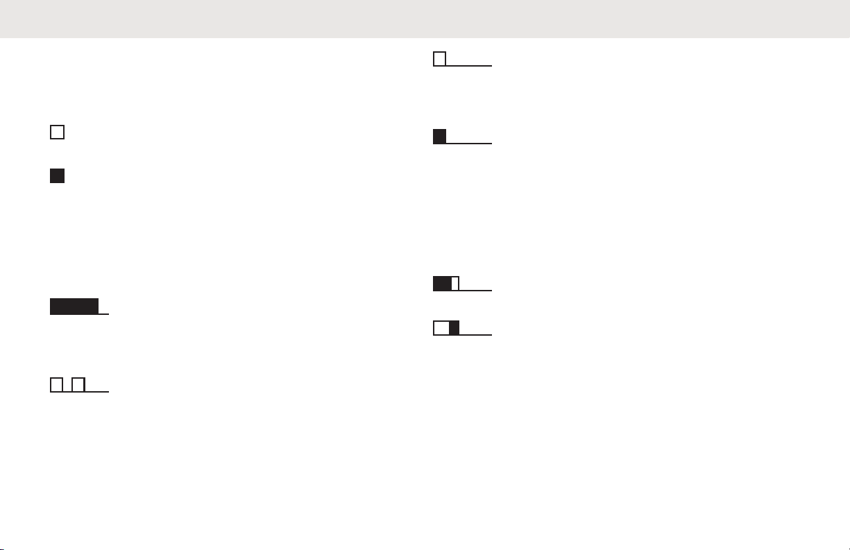
Icon Information
Throughout this publication, the icons described are used
to indicate features supported in either the conventional
analog or conventional digital mode.
Indicates a conventional Analog Mode-Only feature.
Indicates a conventional Digital Mode-Only feature.
For features that are available in both conventional analog
and digital modes, both icons are not shown.
Conventional Analog and Digital Modes
Each channel in your radio can be configured as a
conventional analog or conventional digital channel.
1 : Channel Selector Knob
Certain features are unavailable when switching from
digital to analog mode.
Your radio also has features available in both analog and
digital modes. The minor differences in the way each
feature works do not affect the performance of your radio.
13
Page 14

English
NOTICE:
Your radio also switches between digital and analog
modes during a dual mode scan. See Scan on page
35 for more information.
14
Page 15

English
Basic Operations
This chapter explains the operations to get you started on
using the radio.
Charging the Battery
Your radio is powered by a Lithium-Ion (Li-lon) battery.
• To comply with warranty terms and avoid damages,
charge the battery using a Motorola Solutions
charger exactly as described in the charger user
guide.
All chargers can charge only Motorola Solutions
authorized batteries. Other batteries may not charge.
Motorola Solutions recommends that your radio
remains powered off while charging.
Charge a new battery 14 to 16 hours before initial
•
use for best performance.
Attaching the Battery
Follow the procedure to attach the battery to your radio.
1 Align the battery with the rails on the back of the
radio.
2 Press the battery firmly, and slide upwards until the
latch snaps into place.
3 Slide battery latch into lock position.
Removing the Battery
Follow the procedure to remove the battery from your radio.
Ensure that the radio is turned off.
15
Page 16

1
English
1 Move the battery latch into unlock position and hold.
1 : Battery Latch
2 Slide the battery down and lift off the rails.
16
Attaching the Antenna
Follow the procedure to attach the antenna to your radio.
Ensure that the radio is turned off.
Set the antenna in the receptacle and turn clockwise
until snug to provide best protection against water
and dust.
Page 17

NOTICE:
To remove the antenna, turn the antenna
counterclockwise.
English
Align the grooves on the clip with those on the
battery and press downwards until you hear a click.
CAUTION:
If the antenna must be replaced, ensure that only
MOTOTRBO antennas are used. Neglecting this
damages your radio. See Antennas on page 42 for
a list of available antennas.
Attaching the Belt Clip
Follow the procedure to attach the belt clip to your radio.
Removing the Belt Clip
Follow the procedure to remove the belt clip from your
radio.
1 To remove the clip, press the belt clip tab away from
the battery using a key.
2 Slide the clip upwards and away from the radio.
17
Page 18

English
Powering Up the Radio
Follow the procedure to power up your radio.
Rotate the On/Off/Volume Control Knob clockwise
until a click sounds.
If successful:
• A tone sounds.
• The green LED lights up.
If the Tones/Alerts function is disabled, there is no tone
upon powering up.
Check your battery if your radio does not power up. Make
sure that it is charged and properly attached. Contact your
dealer if your radio still does not power up.
Adjusting the Volume
Follow the procedure to change the volume level of your
radio.
Do one of the following:
• Turn the
clockwise to increase the volume.
• Turn the On/Off/Volume Control Knob
counterclockwise to decrease the volume.
On/Off/Volume Control Knob
18
Page 19

1
English
1 : On/Off Volume Control Knob
NOTICE:
Your radio can be programmed to have a
minimum volume offset where the volume
level cannot be lowered past the
programmed minimum volume. Check with
your dealer or system administrator for more
information.
19
Page 20

1
2
3
4
5
6
7
8
9
English
Radio Controls
This chapter explains the buttons and functions to control
the radio.
1 Antenna
2 Push-to-Talk (PTT) Button
3 Side Button 1
4 Side Button 2
5 Microphone
6 Speaker
7 LED Indicator
8 On/Off/Volume Control Knob
9 Channel Selector Knob
1
1
Programmable Buttons
Depending on the duration of a button press, your dealer
can program the programmable buttons as shortcuts to
radio functions.
Short press
Pressing and releasing rapidly.
Long press
Pressing and holding for the programmed duration.
1
These buttons are programmable.
20
Page 21

English
Press and hold
Keeping the button pressed.
The programmed duration of a button press is applicable to
all assignable radio/utility functions or settings.
Assignable Radio Functions
The following radio functions can be assigned to the
programmable buttons.
Battery Type
Allows selection of battery type between Li-Ion and
NiMH.
Mic AGC
Toggles the internal microphone automatic gain control
(AGC) on or off.
Monitor
Monitors a selected channel for activity.
Nuisance Channel Delete
Temporarily removes an unwanted channel, except for
the Selected Channel, from the scan list. The Selected
Channel refers to the selected zone or channel
combination of the user from which scan is initiated.
One Touch Access
Directly initiates a predefined Private, Phone or Group
Call, a Call Alert, or a Quick Text message.
Permanent Monitor
Monitors a selected channel for all radio traffic until
function is disabled.
Repeater/Talkaround
Toggles between using a repeater and communicating
directly with another radio.
Scan
Toggles scan on or off.
Voice Announcement On/Off
Toggles voice announcement on or off.
Voice Announcement for Channel
Plays zone and channel announcement voice
messages for the current channel. This function is
unavailable when Voice Announcement is disabled.
Voice Operating Transmission (VOX)
Toggles VOX on or off.
21
Page 22

English
Assignable Settings or Utility Functions
The following radio settings or utility functions can be
assigned to the programmable buttons.
Tones/Alerts
Toggles all tones and alerts on or off.
Power Level
Toggles transmit power level between high and low.
Squelch
Toggles squelch level between tight and normal.
Push-To-Talk Button
The Push-to-Talk (PTT) button serves two basic purposes:
• While a call is in progress, the PTT button allows the
radio to transmit to other radios in the call. The
microphone is activated when the PTT button is
pressed.
• While a call is not in progress, the PTT button is used to
make a new call.
If the Talk Permit Tone is enabled, wait until the short alert
tone ends before talking.
If the Channel Free Indication feature is enabled on your
radio (programmed by your dealer), you hear a short alert
tone the moment the target radio (the radio that is receiving
your call) releases the PTT button, indicating the channel is
free for you to respond.
You hear a continuous Talk Prohibit Tone if your call is
interrupted. You should release the PTT button if you hear
a continuous Talk Prohibit Tone.
22
Page 23

English
Status Indicators
This chapter explains the status indicators and audio tones
used in the radio.
LED Indicators
LED indicators show the operational status of your radio.
Blinking Red
Radio has failed the self-test upon powering up.
Radio is receiving an emergency transmission.
Radio is transmitting in low battery state.
Radio has moved out of range if Auto-Range
Transponder System is configured.
Solid Green
Radio is powering up.
Radio is transmitting.
Indicates full battery capacity when the programmed
Battery Strength button is pressed.
When pressing the Battery Type button to set the
battery type as NiMH.
Blinking Green
Radio is receiving a call or data.
Radio is detecting activity over the air.
Solid Yellow
Radio is monitoring a conventional channel.
When pressing the Battery Type button to set the
battery type as Li-Ion.
Indicates fair battery charge when programmable button
is pressed.
Blinking Yellow
Radio is scanning for activity.
Radio has yet to respond to a Call Alert.
Radio has Flexible Receive List enabled.
Double Blinking Yellow
Radio is actively searching for a new site.
Radio has yet to respond to a Group Call Alert.
Radio is locked.
23
Page 24
English
Tones
The following are the tones that sound through on the radio
speaker.
Repetitive Tone
A single tone that repeats itself until it is terminated by
the user.
High Pitched Tone
Low Pitched Tone
Audio Tones
Audio tones provide you with audible indications of the
status, or response to data received on the radio.
Continuous Tone
A monotone sound. Sounds continuously until
termination.
Periodic Tone
Sounds periodically depending on the duration set by
the radio. Tone starts, stops, and repeats itself.
24
Momentary Tone
Sounds once for a short duration set by the radio.
Indicator Tones
Indicator tones provide you with audible indications of the
status after an action to perform a task is taken.
Positive Indicator Tone
Negative Indicator Tone
Page 25

English
Zone and Channel Selections
This chapter explains the operations to select a zone or
channel on your radio. A zone is a group of channels.
Your radio supports 1 zone with a maximum of 16
channels.
Each channel can be programmed with different features
and/or support different groups of users.
Selecting Zones
Follow the procedure to select the required zone on your
radio.
Press the programmed Zone Toggle button.
One of the following tone sounds:
Positive Indicator Tone
Radio is in Zone 2.
Negative Indicator Tone
Radio is in Zone 1.
NOTICE:
For all Non-keypad radio, you are
recommended to enable Voice
Announcement feature for selecting zone.
The Voice Announcement feature can only
be enabled through CPS.
Selecting Channels
Follow the procedure to select the required channel on your
radio after you have selected a zone.
Turn the Channel Selector Knob to select the
channel, subscriber ID, or group ID.
25
Page 26

English
Calls
This chapter explains the operations to receive, respond to,
make, and stop calls.
You can select a subscriber alias or ID, or group alias or ID
after you have selected a channel by using one of these
features:
Programmed One Touch Access Button
This method is used for Group and Private Calls only.
You can only have one ID assigned to a One Touch
Access button with a short or long programmable
button press.
Volume/Channel Selector Knob
This method manually selects a subscriber alias or ID,
or group alias or ID.
The LED lights up solid green while the radio is transmitting
and blinks green when the radio is receiving.
Group Calls
Your radio must be configured as part of a group to receive
a call from or make a call to the group of users.
Making Group Calls
Follow the procedure to make Group Calls on your radio.
1 Do one of the following:
•
Select a channel with the active group alias or ID.
Press the programmed One Touch Access
•
button.
2 Press the PTT button to make the call.
The green LED lights up.
3 Do one of the following:
• Wait for the Talk Permit Tone to end and speak
clearly into the microphone if enabled.
Wait for the PTT Sidetone to end and speak
•
clearly into the microphone if enabled.
4 Release the PTT button to listen.
The green LED blinks when the target radio
responds.
26
Page 27

English
5
If the Channel Free Indication feature is enabled,
you hear a short alert tone the moment the
transmitting radio releases the PTT button, indicating
the channel is free for you to respond. Press the PTT
button to respond to the call.
The call ends when there is no voice activity for a
predetermined period.
Responding to Group Calls
To receive a call from a group of users, your radio must be
configured as part of that group. Follow the procedure to
respond to Group Calls on your radio.
When you receive a Group Call:
• The green LED blinks.
•
Your radio unmutes and the incoming call sounds
through the speaker.
1 Do one of the following:
If the Channel Free Indication feature is
•
enabled, you hear a short alert tone the moment
the transmitting radio releases the PTT button,
indicating the channel is free for you to respond.
Press the
If the Voice Interrupt feature is enabled, press
•
the PTT button to interrupt the audio from the
transmitting radio and free the channel for you to
respond.
The green LED lights up.
2 Do one of the following:
• Wait for the Talk Permit Tone to end and speak
clearly into the microphone if enabled.
• Wait for the PTT Sidetone to end and speak
clearly into the microphone if enabled.
3 Release the PTT button to listen.
The call ends when there is no voice activity for a
predetermined period.
PTT button to respond to the call.
27
Page 28

English
Private Calls
A Private Call is a call from an individual radio to another
individual radio.
There are two ways to set up a Private Call. The first type
sets up the call after performing a radio presence check,
while the second type sets up the call immediately. Only
one of these types can be programmed to your radio by
your dealer.
If this feature is not enabled, a negative indicator tone
sounds when you make a Private Call through the One
Touch Access button or the Channel Selector Knob.
•
Press the programmed One Touch Access
button.
2 Press the PTT button to make the call.
The green LED lights up.
3 Wait for the Talk Permit Tone to end and speak
clearly into the microphone if enabled.
4 Release the PTT button to listen.
The green LED blinks when the target radio
responds.
Making Private Calls
Your radio must be programmed to initiate a Private Call. If
this feature is not enabled, a negative indicator tone
sounds when you initiate the call. Follow the procedure to
make Private Calls on your radio.
1 Do one of the following:
• Select a channel with the active subscriber alias
or ID.
28
5
If the Channel Free Indication feature is enabled,
you hear a short alert tone the moment the
transmitting radio releases the PTT button, indicating
the channel is free for you to respond. Press the PTT
button to respond to the call.
The call ends when there is no voice activity for a
predetermined period. A tone sounds.
Page 29

English
Responding to Private Calls
Follow the procedure to respond to Private Calls on your
radio.
When you receive a Private Call:
• The green LED blinks.
•
Your radio unmutes and the incoming call sounds
through the speaker.
1 Do one of the following:
If the Channel Free Indication feature is
•
enabled, you hear a short alert tone the moment
the transmitting radio releases the PTT button,
indicating the channel is free for you to respond.
Press the PTT button to respond to the call.
• If the Transmit Interrupt Remote Dekey feature
is enabled, press the PTT button to stop an
ongoing interruptible call and free the channel for
you to respond.
The green LED lights up.
2 Wait for the Talk Permit Tone to end and speak
clearly into the microphone if enabled.
3 Release the PTT button to listen.
The call ends when there is no voice activity for a
predetermined period.
All Calls
An All Call is a call from an individual radio to every radio
on the channel. An All Call is used to make important
announcements, requiring full attention from the user. The
users on the channel cannot respond to an All Call.
Receiving All Calls
When you receive an All Call:
• A tone sounds.
•
The green LED blinks.
• Your radio unmutes and the incoming call sounds
through the speaker.
An All Call does not wait for a predetermined period before
ending.
If the Channel Free Indication feature is enabled, you
hear a short alert tone when the transmitting radio releases
29
Page 30

English
the PTT button, indicating the channel is free for you to
use.
You cannot respond to an All Call.
NOTICE:
The radio stops receiving the All Call if you switch to
a different channel while receiving the call. You are
able to continue with any programmed button
not
functions until the end of an All Call.
Broadcast Voice Calls
A Broadcast Voice Call is a one-way voice call from any
user to an entire talkgroup.
The Broadcast Voice Call feature allows only the call
initiating user to transmit to the talkgroup, while the
recipients of the call cannot respond (no Call Hang Time).
Your radio must be programmed to allow you to use this
feature. Check with your dealer or system administrator for
more information.
Making Broadcast Voice Calls
Program your radio to make Broadcast Voice Calls.
1 Select a channel with the active group alias or ID.
2 Press the PTT button to make the call.
The radio returns to the previous menu after the call ends.
Receiving Broadcast Voice Calls
When you receive a Broadcast Voice Call:
• A tone sounds.
The green LED blinks.
•
• Your radio unmutes and the incoming call sounds
through the speaker.
A Broadcast Voice Call does not wait for a predetermined
period before ending.
You cannot respond to a Broadcast Voice Call.
30
Page 31

English
NOTICE:
The radio stops receiving the Broadcast Voice Call if
you switch to a different channel while receiving the
call. You cannot continue with any programmed
button functions until the end of the Broadcast Voice
Call.
Unaddressed Calls
An Unaddressed Call is a group call to one of the 16
predefined group IDs.
This feature is configured using CPS-RM. A contact for one
of the predefined IDs is required to initiate and/or receive
an Unaddressed Call. Check with your dealer or system
administrator for more information.
Making Unaddressed Calls
1 Select a channel with the active group alias or ID.
2 Press the PTT button to make the call.
3 Release the PTT button to listen.
A momentary tone sounds.
4 If the Channel Free Indication feature is enabled,
you hear a short alert tone the moment the
transmitting radio releases the PTT button, indicating
that the channel is free for you to respond. Press the
PTT button to respond to the call.
The call ends when there is no voice activity for a
predetermined period.
Responding to Unaddressed Calls
When you receive an Unaddressed Call:
• The green LED blinks.
•
A momentary tone sounds.
• Your radio unmutes and the incoming call sounds
through the speaker.
1 Do one of the following:
• If the Channel Free Indication feature is enabled,
you hear a short alert tone the moment the
transmitting radio releases the PTT button,
31
Page 32

English
indicating the channel is free for you to respond.
Press the PTT button to respond to the call.
• If the Voice Interrupt feature is enabled, press the
PTT button to interrupt the audio from the
transmitting radio and free the channel for you to
respond.
2 Release the PTT button to listen.
The call ends when there is no voice activity for a
predetermined period.
Open Voice Channel Mode (OVCM)
An Open Voice Channel Mode (OVCM) allows a radio that
is not preconfigured to work in a particular system to both
receive and transmit during a group or individual call.
The OVCM group call also supports broadcast calls.
Program your radio to use this feature. Check with your
dealer or system administrator for more information.
Making OVCM Calls
Your radio must be programmed for you to make an OVCM
Call. Follow the procedure to make OVCM Calls on your
radio.
1 Select a channel with the active group alias or ID.
2 Press the PTT button to make the call.
Responding to OVCM Calls
When you receive an OVCM Call:
• The green LED blinks.
•
Your radio unmutes and the incoming call sounds
through the speaker.
1 Do one of the following:
• If the Channel Free Indication feature is enabled,
you hear a short alert tone the moment the
transmitting radio releases the PTT button,
indicating the channel is free for you to respond.
Press the PTT button to respond to the call.
32
Page 33

• If the Voice Interrupt feature is enabled, press the
PTT button to interrupt the audio from the
transmitting radio and free the channel for you to
respond.
2 Release the PTT button to listen.
The call ends when there is no voice activity for a
predetermined period.
English
33
Page 34

English
Advanced Features
This chapter explains the operations of the features
available in your radio.
Your dealer or system administrator may have customized
your radio for your specific needs. Check with your dealer
or system administrator for more information.
Talkaround
This feature allows you to continue communication when
your repeater is not operational, or when your radio is out
of range from the repeater but within talking range of other
radios.
The talkaround setting is retained even after powering
down.
Toggling Between Repeater and Talkaround Modes
Follow the procedure to toggle between Repeater and
Talkaround modes on your radio.
Press the programmed
button.
One of the following tones sounds:
Positive Indicator Tone
Radio is in talkaround mode.
Negative Indicator Tone
Radio is in repeater mode.
Repeater/Talkaround
Monitor Feature
The monitor feature is used to make sure that a channel is
free before transmitting.
Monitoring Channels
Follow the procedure to monitor channels.
1 Long press the programmed Monitor button.
The yellow LED double blinks when the channel is
busy.
34
Page 35

English
2 Press the PTT button to talk. Release the PTT
button to listen.
Permanent Monitor
The Permanent Monitor feature is used to continuously
monitor a selected channel for activity.
Turning Permanent Monitor On or Off
Follow the procedure to turn Permanent Monitor on or off
on your radio.
Press the programmed Permanent Monitor button.
When the radio enters the mode:
• An alert tone sounds.
•
The yellow LED lights up.
When the radio exits the mode:
• An alert tone sounds.
• The yellow LED turns off.
Scan Lists
Scan lists are created and assigned to individual channels
or groups. Your radio scans for voice activity by cycling
through the channel or group sequence specified in the
scan list for the current channel or group.
Your radio can support up to 3 scan lists, with a maximum
of 16 members in a list.
Each scan list supports a mixture of both analog and digital
entries.
Scan
Your radio cycles through the programmed scan list for the
current channel looking for voice activity when you start a
scan.
There are two ways of initiating scan:
Main Channel Scan (Manual)
Your radio scans all the channels or groups in your
scan list. On entering scan, your radio may, depending
on the settings, automatically start on the last scanned
active channel or group, or on the channel where scan
was initiated.
35
Page 36

English
Auto Scan (Automatic)
Your radio automatically starts scanning when you
select a channel or group that has Auto Scan enabled.
Turning Scan On or Off
Follow the procedure to turn scan on or off on your radio.
Do one of the following:
• Press the programmed Scan
stop Scan.
• Turn the Channel Selector Knob to select a
channel programmed with Auto Scan enabled.
If scan is enabled:
• The yellow LED blinks.
A positive indicator tone sounds.
•
If scan is disabled:
• The LED turns off.
• A negative indicator tone sounds.
button to start or
Responding to Transmissions During Scanning
During scanning, your radio stops on a channel or group
where activity is detected. The radio stays on that channel
for a programmed duration known as hang time. Follow the
procedure to respond to transmissions during scanning.
1
If the Channel Free Indication feature is enabled,
you hear a short alert tone the moment the
transmitting radio releases the PTT button, indicating
the channel is free for you to respond. Press the PTT
button during hang time.
The green LED lights up.
2 Do one of the following:
• Wait for the Talk Permit Tone to end and speak
clearly into the microphone if enabled.
• Wait for the PTT Sidetone to end and speak
clearly into the microphone if enabled.
3 Release the PTT button to listen.
The radio returns to scanning other channels or
groups if you do not respond within the hang time.
36
Page 37

English
Deleting Nuisance Channels
If a channel continually generates unwanted calls or noise,
(termed a "nuisance" channel), you can temporarily remove
the unwanted channel from the scan list. This capability
does not apply to the channel designated as the Selected
Channel. Follow the procedure to delete nuisance channels
on your radio.
1 When your radio locks on to an unwanted or
nuisance channel, press the programmed Nuisance
Channel Delete button until you hear a tone.
2 Release the programmed Nuisance Channel
Delete button.
The nuisance channel is deleted.
Restoring Nuisance Channels
Follow the procedure to restore nuisance channels on your
radio.
Do one of the following:
• Turn the radio off and then power it on again.
• Stop and restart a scan using the programmed
Scan
button.
• Change the channel using the Channel Selector
Knob.
Call Indicator Settings
This feature allows the radio users to configure call or text
message ringing tones. See Turning Radio Tones/Alerts
On or Off
on page 40 for more information.
Call Alert Operation
Call Alert paging enables you to alert a specific radio user
to call you back.
Responding to Call Alerts
Follow the procedure to respond to Call Alerts on your
radio.
When you receive a Call Alert:
• A repetitive tone sounds.
37
Page 38

English
• The yellow LED blinks.
Press the PTT button within 4 seconds of receiving a
Call Alert page to respond with a Private Call.
Auto-Range Transponder System
The Auto-Range Transponder System (ARTS) is an
analog-only feature designed to inform you when your radio
is out-of-range of other ARTS-equipped radios.
ARTS-equipped radios transmit or receive signals
periodically to confirm that they are within range of each
other.
Your radio provides indications of states as follows:
First-Time Alert
A tone sounds.
ARTS-in-Range Alert
A tone sounds, if programmed.
ARTS-Out-of-Range Alert
A tone sounds. The red LED rapidly blinks.
38
NOTICE:
Check with your dealer or system administrator for
more information.
Page 39

English
Utilities
This chapter explains the operations of the utility functions
available in your radio.
Squelch Levels
You can adjust the squelch level to filter out unwanted calls
with low signal strength or channels with noise higher than
normal background.
Normal
This is the default setting.
Tight
This setting filters out unwanted calls and/or
background noise. Calls from remote locations may also
be filtered out.
Setting Squelch Levels
Follow the procedure to set the squelch levels on your
radio.
Press the programmed Squelch button.
One of the following tone sounds:
Positive Indicator Tone
Radio is operating in tight squelch.
Negative Indicator Tone
Radio is operating in normal squelch.
Power Levels
You can customize the power setting to high or low for
each channel.
High
This enables communication with radios located at a
considerable distance from you.
Low
This enables communication with radios in closer
proximity.
Setting Power Levels
Follow the procedure to set the power levels on your radio.
Press the programmed Power Level button.
If successful:
• The Positive Indicator Tone sounds.
39
Page 40

English
• Radio transmits at low power.
If unsuccessful:
• The Negative Indicator Tone sounds.
Radio transmits at high power.
•
Voice Operating Transmission
The Voice Operating Transmission (VOX) allows you to
initiate a hands-free voice-activated call on a programmed
channel. The radio automatically transmits, for a
programmed period, whenever the microphone on the
VOX-capable accessory detects voice.
You can enable or disable VOX by doing one of the
following:
• Turn the radio off and then power it on again to enable
VOX.
•
Change the channel by using the Channel Selector
knob to enable VOX.
• Turn VOX on or off by using the programmed VOX
button.
• Press the PTT button during radio operation to disable
VOX.
If the Talk Permit Tone is enabled, use a trigger word to
initiate the call. Wait for the Talk Permit Tone to finish
before speaking clearly into the microphone. See Turning
Talk Permit Tone On or Off for more information.
NOTICE:
Turning this feature on or off is limited to radios with
this function enabled. Check with your dealer or
system administrator for more information.
Turning Radio Tones/Alerts On or Off
You can enable and disable all radio tones and alerts, if
needed, except for incoming Emergency alert tone . Follow
the procedure to turn tones and alerts on or off on your
radio.
Press the programmed All Tones/Alerts
If successful:
• The Positive Indicator Tone sounds.
• All tones and alerts are turned on.
If unsuccessful:
• The Negative Indicator Tone sounds.
button.
40
Page 41

• All tones and alerts are turned off.
English
41
Page 42

English
Authorized Accessories List
Antennas
• UHF, 403–433 MHz, 9 cm Stubby Antenna
(PMAE4002_)
UHF, 430–470 MHz, 9 cm Stubby Antenna
•
(PMAE4003_)
• UHF, 465–495 MHz, 9 cm Stubby Antenna
(PMAE4006_)
• UHF, 403–520 MHz, Antenna Whip (PMAE4016_)
Batteries
• High Capacity Li-Ion, 2150 mAh Battery (PMNN4080_)
• Li-Ion, 1750 mAh IP54 Battery (PMNN4476_)
Cables
• Programming Cable USB (PMKN4128_)
Carry Devices
• Universal Chest Pack (HLN6602_)
• Spring Belt Clip (For 1.5 in. Belt Width)(HLN9844_)
• Waterproof Bag, Includes Large Carry Strap
(HLN9985_)
• Adjustable Black Nylon Carrying Strap (Attaches to DRing on Carry Case)(NTN5243_)
•
Break-A-Way Chest Pack (RLN4570_)
• Universal Radio Pack and Utility Case (Fanny Pack)
(RLN4815_)
Chargers
• Switch Mode Power Supply for Single-Unit Chargers,
Low Noise, 18 W, US/NA Plug (25009297001)
• Tri-Chemistry Single-Unit Rapid-Rate Charger
(PMLN5228_)
• Charger SWM, Power Supply, Argentina Plug
(EPNN9292_)
• Charger SWM, Power Supply, Euro Plug (with
2571886T01)(EPNN9286_)
• Power Supply, Charger Switching Mode, NA/LA Plug
(EPNN9288_)
• Power Supply, Brazil plug (EPNN9356_)
42
Page 43

English
Earbuds and Earpieces
• Receive-Only Earbud (AARLN4885_)
• D-Shell Receive Only Earpiece (One Size) for Remote
Speaker Microphone (PMLN4620_)
• Ear Receiver with In-Line Microphone/PTT/VOX Switch
(Mag One)(PMLN6531_)
• Swivel Earpiece with In-Line Microphone and PTT
(PMLN6532_)
• Earset with combined microphone and PTT
(PMLN6533_)
• Earbud with In-Line Microphone/PTT/VOX Switch (Mag
One)(PMLN6534_)
• D-Style Earpiece with Microphone/PTT (PMLN6535_)
• Earset with Boom Mic and In-Line PTT/VOX Switch
(Mag One) (PMLN6537_)
• Receive-Only Earpiece (RLN4941_)
Headsets and Headset Accessories
• Lightweight Headset with Swivel Boom Microphone
(PMLN6538_)
• Lightweight Temple Transducer Headset (PMLN6541_)
• MagOne Ultra-Lite Headset, behind-the-head,
adjustable with boom microphone and In-Line PTT
(PMLN6542_)
• Heavy Duty Headset, Noise Cancelling Boom Mic
Headset (PMLN6854_)
Medium Weight Over-the-Head Dual Muff Headset
•
(PMLN7468_)
Remote Speaker Microphones
• Remote Speaker Microphone with 3.5 mm Audio Jack
(PMMN4013_)
• Remote Speaker Microphone IP57 (PMMN4029_)
• Remote Speaker Microphone (Mag One) (PMMN4092_)
Surveillance Accessories
• 2-Wire Surveillance Kit with Clear Acoustic Earpiece,
Beige (Palm Garden)(PMLN6445_)
• 2-Wire Surveillance Kit, with Clear Acoustic Earpiece,
Black (Palm Garden)(PMLN6530_)
• 2-Wire Surveillance Kit with Quick Disconnect Acoustic
Tube, Black (OTTO)(PMLN6536_)
43
Page 44

English
NOTICE:
Consult your authorized Motorola Solutions dealer
on the availability of these accessories.
44
Page 45

Batteries and Chargers Warranty
The Workmanship Warranty
The workmanship warranty guarantees against defects in
workmanship under normal use and service.
All MOTOTRBO Batteries 24 Months
The Capacity Warranty
The capacity warranty guarantees 80% of the rated
capacity for the warranty duration.
English
Nickel Metal-Hydride
(NiMH) or Lithium-Ion (Lilon) Batteries
12 Months
45
Page 46

English
Limited Warranty
MOTOROLA SOLUTIONS COMMUNICATION PRODUCTS
I. WHAT THIS WARRANTY COVERS AND FOR HOW LONG:
Motorola Solutions, Inc. ("Motorola Solutions") warrants the
Motorola Solutions manufactured Communication Products
listed below ("Product") against defects in material and
workmanship under normal use and service for a period of
time from the date of purchase as scheduled below:
Portable Radios Two (2) Years
Product Accessories (Excluding Batteries and
Chargers)
MagOne Accessories Six (6) Months
Motorola Solutions, at its option, will at no charge either
repair the Product (with new or reconditioned parts),
One (1) Year
replace it (with a new or reconditioned Product), or refund
the purchase price of the Product during the warranty
period provided it is returned in accordance with the terms
of this warranty. Replaced parts or boards are warranted
for the balance of the original applicable warranty period.
All replaced parts of Product shall become the property of
Motorola Solutions.
This express limited warranty is extended by Motorola
Solutions to the original end user purchaser only and is not
assignable or transferable to any other party. This is the
complete warranty for the Product manufactured by
Motorola Solutions. Motorola Solutions assumes no
obligations or liability for additions or modifications to this
warranty unless made in writing and signed by an officer of
Motorola Solutions.
Unless made in a separate agreement between Motorola
Solutions and the original end user purchaser, Motorola
Solutions does not warrant the installation, maintenance or
service of the Product.
Motorola Solutions cannot be responsible in any way for
any ancillary equipment not furnished by Motorola
Solutions which is attached to or used in connection with
the Product, or for operation of the Product with any
ancillary equipment, and all such equipment is expressly
excluded from this warranty. Because each system which
46
Page 47

English
may use the Product is unique, Motorola Solutions
disclaims liability for range, coverage, or operation of the
system as a whole under this warranty.
II. GENERAL PROVISIONS
This warranty sets forth the full extent of Motorola Solutions
responsibilities regarding the Product. Repair, replacement
or refund of the purchase price, at Motorola Solutions
option, is the exclusive remedy. THIS WARRANTY IS
GIVEN IN LIEU OF ALL OTHER EXPRESS
WARRANTIES. IMPLIED WARRANTIES, INCLUDING
WITHOUT LIMITATION, IMPLIED WARRANTIES OF
MERCHANTABILITY AND FITNESS FOR A PARTICULAR
PURPOSE, ARE LIMITED TO THE DURATION OF THIS
LIMITED WARRANTY. IN NO EVENT SHALL MOTOROLA
SOLUTIONS BE LIABLE FOR DAMAGES IN EXCESS OF
THE PURCHASE PRICE OF THE PRODUCT, FOR ANY
LOSS OF USE, LOSS OF TIME, INCONVENIENCE,
COMMERCIAL LOSS, LOST PROFITS OR SAVINGS OR
OTHER INCIDENTAL, SPECIAL OR CONSEQUENTIAL
DAMAGES ARISING OUT OF THE USE OR INABILITY
TO USE SUCH PRODUCT, TO THE FULL EXTENT SUCH
MAY BE DISCLAIMED BY LAW.
III. STATE LAW RIGHTS:
SOME STATES DO NOT ALLOW THE EXCLUSION OR
LIMITATION OF INCIDENTAL OR CONSEQUENTIAL
DAMAGES OR LIMITATION ON HOW LONG AN IMPLIED
WARRANTY LASTS, SO THE ABOVE LIMITATION OR
EXCLUSIONS MAY NOT APPLY.
This warranty gives specific legal rights, and there may be
other rights which may vary from state to state.
IV. HOW TO GET WARRANTY SERVICE
You must provide proof of purchase (bearing the date of
purchase and Product item serial number) in order to
receive warranty service and, also, deliver or send the
Product item, transportation and insurance prepaid, to an
authorized warranty service location. Warranty service will
be provided by Motorola Solutions through one of its
authorized warranty service locations. If you first contact
the company which sold you the Product (for example,
dealer or communication service provider), it can facilitate
your obtaining warranty service. You can also call Motorola
Solutions at 1-800-927-2744.
47
Page 48

English
V. WHAT THIS WARRANTY DOES NOT COVER
1 Defects or damage resulting from use of the Product in
other than its normal and customary manner.
2 Defects or damage from misuse, accident, water, or
neglect.
3 Defects or damage from improper testing, operation,
maintenance, installation, alteration, modification, or
adjustment.
4 Breakage or damage to antennas unless caused directly
by defects in material workmanship.
5 A Product subjected to unauthorized Product
modifications, disassembles or repairs (including,
without limitation, the addition to the Product of nonMotorola Solutions supplied equipment) which adversely
affect performance of the Product or interfere with
Motorola Solutions normal warranty inspection and
testing of the Product to verify any warranty claim.
6 Product which has had the serial number removed or
made illegible.
7 Rechargeable batteries if:
• any of the seals on the battery enclosure of cells are
broken or show evidence of tampering.
• the damage or defect is caused by charging or using
the battery in equipment or service other than the
Product for which it is specified.
8 Freight costs to the repair depot.
9 A Product which, due to illegal or unauthorized
alteration of the software/firmware in the Product, does
not function in accordance with Motorola Solutions
published specifications or the FCC certification labeling
in effect for the Product at the time the Product was
initially distributed from Motorola Solutions.
10 Scratches or other cosmetic damage to Product
surfaces that does not affect the operation of the
Product.
11 Normal and customary wear and tear.
VI. PATENT AND SOFTWARE PROVISIONS
Motorola Solutions will defend, at its own expense, any suit
brought against the end user purchaser to the extent that it
is based on a claim that the Product or parts infringe a
United States patent, and Motorola Solutions will pay those
48
Page 49

English
costs and damages finally awarded against the end user
purchaser in any such suit which are attributable to any
such claim, but such defense and payments are
conditioned on the following:
1 Motorola Solutions will be notified promptly in writing by
such purchaser of any notice of such claim,
2 Motorola Solutions will have sole control of the defense
of such suit and all negotiations for its settlement or
compromise, and
3 Should the Product or parts become, or in Motorola
Solutions opinion be likely to become, the subject of a
claim of infringement of a United States patent, that
such purchaser will permit Motorola Solutions, at its
option and expense, either to procure for such
purchaser the right to continue using the Product or
parts or to replace or modify the same so that it
becomes non-infringing or to grant such purchaser a
credit for the Product or parts as depreciated and accept
its return. The depreciation will be an equal amount per
year over the lifetime of the Product or parts as
established by Motorola Solutions.
Motorola Solutions will have no liability with respect to any
claim of patent infringement which is based upon the
combination of the Product or parts furnished hereunder
with software, apparatus or devices not furnished by
Motorola Solutions, nor will Motorola Solutions have any
liability for the use of ancillary equipment or software not
furnished by Motorola Solutions which is attached to or
used in connection with the Product. The foregoing states
the entire liability of Motorola Solutions with respect to
infringement of patents by the Product or any parts thereof.
Laws in the United States and other countries preserve for
Motorola Solutions certain exclusive rights for copyrighted
Motorola Solutions software such as the exclusive rights to
reproduce in copies and distribute copies of such Motorola
Solutions software. Motorola Solutions software may be
used in only the Product in which the software was
originally embodied and such software in such Product may
not be replaced, copied, distributed, modified in any way, or
used to produce any derivative thereof. No other use
including, without limitation, alteration, modification,
reproduction, distribution, or reverse engineering of such
Motorola Solutions software or exercise of rights in such
Motorola Solutions software is permitted. No license is
granted by implication, estoppel or otherwise under
Motorola Solutions patent rights or copyrights.
VII. GOVERNING LAW
This Warranty is governed by the laws of the State of
Illinois, U.S.A.
49
Page 50

www.motorolasolutions.com/mototrbo
Motorola Solutions, Inc.
500 W Monroe Street
Chicago, IL 60661 U.S.A.
MOTOROLA, MOTO, MOTOROLA SOLUTIONS and the Stylized M Logo are trademarks or registered
trademarks of Motorola Trademark Holdings, LLC and are used under license. All other trademarks are
the property of their respective owners. © 2019 Motorola Solutions, Inc. All rights reserved.
 Loading...