

Page 1
XPR 6300/6350/6500/6550
Digital Portable Radio
Quick Reference Card
Product Safety and RF Exposure Compliance
Before using this product, read the operating instructions
for safe usage contained in the Product Safety and RF
!
Exposure booklet enclosed with your radio.
Caution
This radio is restricted to occupational use only to satisfy
FCC RF energy exposure requirements. Before using this
product, read the RF energy awareness information and
operating instructions in the Product Safety and RF
Exposure booklet enclosed with your radio (Motorola
Publication part number 6881095C98) to ensure
compliance with RF energy exposure limits.
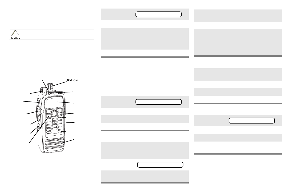
On/Off/
Volume Knob
Top Side
Button
_ _ _ _ _ _ _
PTT Button
Side Button 1
_ _ _ _ _ _ _
Side Button 2
_ _ _ _ _ _ _
Menu Button
ATT ENTI ON!
3-Position
16-Position
Select Knob
Top Button
_ _ _ _ _ _ _
Display
Home button
Keypad
Speaker
Select a Zone Using the Menu
1 Press U until
ZONE
2 Press D, E, or F directly below ZONE.
3 Press U until the zone you desire is shown
OR
Use the keypad directly to dial the zone
number.
4 Press h to confirm, or press PTT to transmit.
Select a Channel
Method 1: Using the Select Knob
After selecting the desired zone, turn the 16position Select Knob to the desired channel.
Method 2: Using the Menu
1 Press U until
2 Press D, E, or F directly below CHAN.
3 Press U until channel you desire is shown
4 Press h to confirm, or press PTT to transmit.
Send an Emergency Alarm
1 Radio on and press Emergency button. You
see red LED; you hear short, medium-pitched
tone.
CHAN
Send Silent Emergency Alarm
1 Radio on and press Emergency button. You
see no LED; you hear no tone.
2 Press PTT.
3 Alarm continues until you exit by:
• Press and hold Emergency button for one
second.
OR
•Press PTT again.
Answer a Phone Call
1 Phone-like ringing, LED flashes GREEN,
PHONE CALL and m are displayed.
2 Press Call Response button.
3 Press PTT button to talk; release to listen.
4 Press h to hang up.
Send a Phone Call
1 Press U until
PHON
2 Press D, E, or F directly below PHON.
3 Press U or V to scroll to phone number.
4 Press PTT (or Quick Access button, if
programmed) to talk, release to listen.
Write your radio’s programmed features on
the dotted lines.
2 Display shows .
EMERGENCY
3 When acknowledgment is received, you hear
four tones;alarm ends;radio exits emergency.
Page 2
Display Status Symbols Menu Entries (Use With Menu Navigation)
Call Received. Receiving an individual
call
m
View/Program Mode. The radio is in the
p
view or program mode; On Steady = view
p
mode; Flashing = program mode
Received Signal Strength Indication
s
Received signal strength for the
(RSSI).
current site (trunking only). The more
stripes in the symbol, the stronger the
signal.
Battery
b
• Conventional = Flashes when the
battery is low.
• Smart = The number of bars (0-3)
shown indicates the charge remaining
in your battery.
Note: Smart battery will be available at a
future date.
r
Talkaround. You are talking directly to
another radio or through a repeater;
On = direct;
Off = repeater
Monitor (Carrier Squelch). This channel
C
is being monitored.
Scan. The radio is scanning a scan list
T
Entry Menu Selection Page
BATT *Smart Battery 17
CALL Private Call 58
CHAN Select a Channel 25
CLCK Edit Time and Date 68
DIR Repeater/Direct 64
MUTE Keypad Mute 35
NAME Text Select 47
NUM Number Select 45
PAGE Call Alert Page 60
*Available at a future date.
Menu Navigation
U to find Menu Entry
D, or E, or F directly below
Menu Entry to select
h to exit
Entry Menu Selection Page
PHON Phone 53
PROG Editing 45
PSWD Password 34
PWR TX Power Level 31
RPGM Reprogram Request 76
SCAN Scan On/Off 49
SITE Site Lock 80
TGRP Talkgroup Call 63
VIEW Viewing a List 43
ZONE Select a Zone 24
V or U to scroll through sub-list
D, or E, or F directly below
Menu Entry to select
Page 3

XPR 6300/6350/6500/6550
Digital Portable Radio
User Guide
6816821H01
MOTOROLA, the Stylized Logo and CommPort are registered in the U.S.
Patent & Trademark Office. All other product or service names are the
property of their respective owners.
© Motorola, Inc. 2006. All Rights Reserved.
Page 4

Product Safety and RF Exposure Compliance
Before using this product, read the operating
instructions for safe usage contained in the Product
!
Caution
This radio is restricted to occupational use only to satisfy FCC
RF energy exposure requirements. Before using this product,
read the RF energy awareness information and operating
instructions in the Product Safety and RF Exposure booklet
enclosed with your radio (Motorola Publication part number
6881095C98) to ensure compliance with RF energy exposure
limits.
For a list of Motorola-approved antennas, batteries, and other
accessories, visit the following web site which lists approved
accessories: http://www.motorola.com/governmentandenterprise
Computer Software Copyrights
The Motorola products described in this manual may include
copyrighted Motorola computer programs stored in semiconductor
memories or other media. Laws in the United States and other
countries preserve for Motorola certain exclusive rights for
copyrighted computer programs, including, but not limited to, the
exclusive right to copy or reproduce in any form the copyrighted
computer program. Accordingly, any copyrighted Motorola computer
programs contained in the Motorola products described in this
manual may not be copied, reproduced, modified, reverseengineered, or distributed in any manner without the express written
permission of Motorola. Furthermore, the purchase of Motorola
products shall not be deemed to grant either directly or by implication,
estoppel, or otherwise, any license under the copyrights, patents or
patent applications of Motorola, except for the normal non-exclusive
license to use that arises by operation of law in the sale of a product.
Safety and RF Exposure booklet enclosed with your
radio.
ATTENTION!
iii
Page 5

Documentation Copyrights
No duplication or distribution of this document or any portion thereof
shall take place without the express written permission of Motorola.
No part of this manual may be reproduced, distributed, or transmitted
in any form or by any means, electronic or mechanical, for any
purpose without the express written permission of Motorola.
Disclaimer
The information in this document is carefully examined, and is
believed to be entirely reliable. However, no responsibility is assumed
for inaccuracies. Furthermore, Motorola reserves the right to make
changes to any products herein to improve readability, function, or
design. Motorola does not assume any liability arising out of the
applications or use of any product or circuit described herein; nor
does it cover any license under its patent rights, nor the rights of
others.
iv
Page 6

Contents
Declaration of Conformity .................................................................. ii
Product Safety and RF Exposure Compliance .................................iii
Computer Software Copyrights .........................................................iii
Documentation Copyrights ............................................................... iv
Disclaimer ........................................................................................ iv
General Radio Operation . . . . . . . . . . . . . . . . . . . . . . . 1
Notations Used in This Manual ......................................................... 1
XPR 6300/6350/6500/6550 Radio .................................................... 2
Physical Features of the XPR 6300/6350/6500/6550 Radio ............. 3
Programmable Features ................................................................... 4
Display .............................................................................................. 5
Backlight ........................................................................................... 5
Status Symbols ................................................................................. 6
Menu Entry (Softkey) ........................................................................ 7
Menu Select Buttons ......................................................................... 7
Menu Entry Features .................................................................. 8
Home Button (h) .............................................................................. 9
Keypad ............................................................................................ 10
LED Indicators ................................................................................ 11
Alert Tones ...................................................................................... 12
Standard Accessories ..................................................................... 15
Battery ...................................................................................... 15
Smart Battery Condition ........................................................... 17
Antenna .................................................................................... 18
Belt Clip .................................................................................... 19
Universal Connector Cover ............................................................. 20
Remote Speaker Microphone Adapter ............................................ 21
Radio On and Off ............................................................................ 23
Turn the Radio On .................................................................... 23
Turn the Radio Off .................................................................... 23
Zones and Channels ....................................................................... 24
Select a Zone ........................................................................... 24
Select a Channel ...................................................................... 25
Receive / Transmit .......................................................................... 27
Without Using the Volume Set and Monitor Buttons ................ 27
Use Preprogrammed Volume Set Button ................................. 28
Use the Preprogrammed Monitor Button .................................. 29
Conventional Mode Operation .................................................. 30
v
Page 7

Contents
Common Radio Features . . . . . . . . . . . . . . . . . . . . . . 31
Selectable Power Level ...................................................................31
Use the Menu ............................................................................31
Using the Preprogrammed TX Power Level Switch ..................32
Radio Lock .......................................................................................33
Unlock Your Radio ....................................................................33
Change Your Password ............................................................34
Mute or Unmute Keypad Tones .......................................................35
Use the Menu ............................................................................35
Using the Preprogrammed Side Button ....................................35
Conventional Squelch Options ........................................................36
Analog Squelch .........................................................................36
Digital Squelch ..........................................................................36
PL Defeat .........................................................................................37
Time-out Timer ................................................................................38
Emergency ......................................................................................39
Send an Emergency Alarm .......................................................39
Send an Emergency Call ..........................................................40
Send a Silent Emergency Alarm ...............................................41
Emergency Keep-Alive .............................................................42
Lists .................................................................................................43
View a List .................................................................................43
Scan List Empty ........................................................................44
Edit a Call, Page, or Phone List Number .........................................45
Use the Menu ............................................................................45
Edit a Call, Page, or Phone List Name ............................................47
Use the Menu ............................................................................47
Scan ................................................................................................49
Turn Scan On and Off ...............................................................49
Delete a Nuisance Channel ......................................................51
Conventional Scan Only ...........................................................52
Telephone Calls (Trunking Only) .....................................................53
Answer a Phone Call ................................................................53
Make a Phone Call ....................................................................54
Phone Call Display and Alert Prompts ......................................56
Private Calls (Trunking Only) ...........................................................57
Answer a Private Call ................................................................57
Make a Private Call ...................................................................58
Call Alert Paging ..............................................................................60
Answer a Call Alert Page ..........................................................60
vi
Page 8

Contents
Make a Call Alert ...................................................................... 61
Conventional Talkgroup Calls
(Conventional Operation Only) ....................................................... 63
Select Talkgroup ....................................................................... 63
Repeater or Direct Operation .......................................................... 64
Select Repeater or Direct Operation ........................................ 64
Special Radio Features. . . . . . . . . . . . . . . . . . . . . . . . 65
PTT ID ............................................................................................. 65
Receive ..................................................................................... 65
Transmit .................................................................................... 65
View Your Radio’s ID Number .................................................. 66
Time and Date ................................................................................. 68
Edit Time and Date ................................................................... 68
Helpful Tips . . . . . . . . . . . . . . . . . . . . . . . . . . . . . . . . . 71
Radio Care ...................................................................................... 71
Cleaning ................................................................................... 71
Handling ................................................................................... 71
Service ............................................................................................ 71
Battery ............................................................................................. 72
Battery Life ............................................................................... 72
Charging the Battery ................................................................. 72
Battery Recycling and Disposal ...................................................... 74
Antenna ........................................................................................... 75
Radio Operating Frequencies ................................................... 75
Accessories . . . . . . . . . . . . . . . . . . . . . . . . . . . . . . . . . 77
Antennas ......................................................................................... 77
Batteries .......................................................................................... 77
Carry Accessories ........................................................................... 78
Belt Clips .................................................................................. 78
Body-Worn ................................................................................ 78
Chargers ......................................................................................... 78
Enhanced and Multi-Unit Line Cords ........................................ 79
Microphones, Remote Speaker ....................................................... 80
Surveillance Accessories ................................................................ 81
Cables ...................................................................................... 81
Earpieces .................................................................................. 81
Headsets and Headset Accessories ......................................... 81
vii
Page 9

Contents
Miscellaneous ..................................................................................82
Glossary . . . . . . . . . . . . . . . . . . . . . . . . . . . . . . . . . . . 83
Commercial Warranty. . . . . . . . . . . . . . . . . . . . . . . . . 87
Index . . . . . . . . . . . . . . . . . . . . . . . . . . . . . . . . . . . . . . 93
viii
Page 10

Table 1: Channel Map
Use the chart below to map the channels (Cx) and zones (Zx) for your radio.
Z1 Z2 Z3 Z4 Z5 Z6
C1
C2
C3
C4
C5
C6
C7
C8
C9
C10
C11
C12
C13
C14
C15
C16
ix
Page 11

Contents
Notes
x
Page 12

General Radio Operation
Notations Used in This Manual
You will notice the use of WARNINGS, CAUTIONS, and Note
throughout this manual. These notations are used to emphasize that
safety hazards exist and that care must be taken or observed.
WARNING: An operational procedure, practice,
!
!
WARNING
!
Caution
Note: A Note is an operational procedure, practice, or condition,
condition, etc. exists which may result in injury
or death if not carefully observed.
CAUTION: An operational procedure, practice,
condition, etc. exists which may result in damage
to the equipment if not carefully observed.
etc. which is essential to emphasize.
The following special notations identify certain items:
Example Description
Light button, or D Buttons and keys are shown in
bold print, or as representative
symbols.
Information appearing in the
PHONE CALL
PHONE Menu entries are shown similar
Press U This means “Press the right side
radio’s display is shown using
the special display font.
to the way they appear in the
radio’s display.
of the 4-Way Navigation
button.”
1
Page 13

General Radio Operation
XPR 6300/6350/6500/6550 Radio
8
10
12
13
9
11
1
2
3
4
5
6
7
2
Page 14

General Radio Operation
Physical Features of the XPR 6300/6350/6500/
6550 Radio
Item Page
1 Antenna 18
2Top Button (programmable)
3 LED 11
4 Display
5 Universal Connector 20
6 Menu Select Buttons 5
7Keypad 7
8 16-Position Knob
(programmable
9 On/Off/Volume Control Knob 10
10 Top Side (Select) Button
(programmable)
11 Push-to-Talk (PTT) Button
12 Side Button 1 (programmable)
13 Side Button 2 (programmable)
3
Page 15

General Radio Operation
Programmable Features
The programmable controls on your radio can be programmed by a
qualified technician to operate certain software-activated features.
The features that can be assigned to these controls, and the page
numbers where these features can be found, are listed below.
Table 1: Programmable Features
Feature Page Feature Page
Call Alert Page 60 Private Call 57
Call Response 53 Repeater/Direct 64
Channel Selection 25 Reprogram Request 76
Dynamic Priority 52 Scan On/Off 49
Emergency 39 Site Lock/Unlock 80
Keypad Mute 35 Site Search 81
Light 5 *Smart Battery 17
Monitor 29 Transmit Power Level 31
Nuisance Delete 51 Volume Set 27
Phone 53 Zone Selection 24
PL Defeat 37
*Available at a future date.
Any references in this manual to controls that are
“preprogrammed” means that a qualified technician must use
the radio’s programming software to assign a feature to a
control.
4
Page 16

General Radio Operation
Display
This figure is typical of what you see on your radio. The 132x34 full
dot matrix black and white liquid crystal display (LCD) shows radio
status, text, and menu entries.
Backlight
If poor light conditions make the display and keypad difficult to read,
turn Auto On/Off the automatic backlight option via radio menu.
This illumination of yellow-green will remain on for a preprogrammed
time before they turn off automatically, or you can turn them off
immediately by pressing the Light button again.
5
Page 17

General Radio Operation
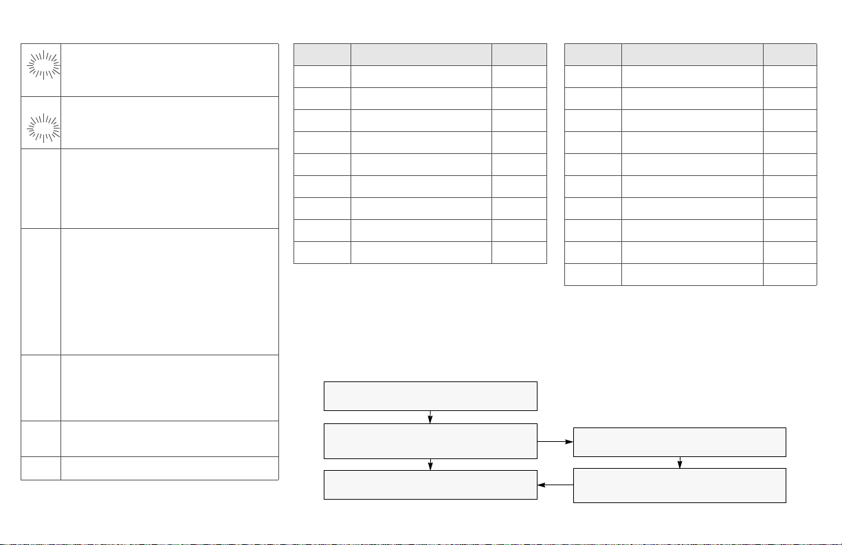
Status Symbols
The top two rows in the display contain symbols indicating the radio’s
status.
Table 2: Status Symbols
Symbol Indication Page
m
p
p
s
b
r
Call Received. Flashes when an Individual Call
is received.
View/Program Mode.
• View a list (steady)
• Program a list (flashing)
Received Signal Strength Indication (RSSI).
The received signal strength for the current site.
Trunked only. The more stripes in the symbol, the
stronger the received signal.
Battery
• Conventional = Flashes when the battery is
low.
• Smart = The number of bars (0-3) shown
indicates the charge remaining in your battery.
Flashes when battery level reaches 10% or less.
Note: Smart battery will be available at a future
date.
Talkaround.
• On = Talking directly to another radio, not
through a repeater. Conventional operation only.
• Off = Talking through a repeater.
57
43
81
15
64
C
T
6
Monitor (Carrier Squelch). The selected
channel is being monitored. Conventional
operation only.
Scan. The radio is scanning a scan list. 49
29
Page 18

General Radio Operation
Menu Entry (Softkey)
The bottom row of the display contains one to three menu entries
(also known as softkeys). The menu entries allow you to select from
one of several menus to access the radio’s features. The menu
entries are accessed using the Menu Select buttons.
Menu Select Buttons
The Menu Select buttons access the menu entries of features that
have been activated by a qualified radio technician. Your radio may
be programmed differently from the following example, but the display
for selecting Scan on or off might look like this:
Example: To turn scan on:
Press D.
The display shows the
selected state.
3 Menu Select
Buttons
T
SCAN ON
ON OFF
7
Page 19

General Radio Operation
Menu Entry Features
In most cases, press U to display the following feature selections.
Table 3: Menu Entry Features
Feature
Call Alert
Page
Channel
Selection
Edit a List PROG 45, 47 Site Lock/
Keypad
Mute
Number
Select
Password PSWD 34 Text Select NAME 47
Phone PHON 54 Time/Date CLCK 68
Private Call CALL 58 Transmit
Radio Lock RADIO
Repeater/
Direct
Menu
Entry
PAGE 61 Reprogram
CHAN 25 Scan On/Off SCAN 49
MUTE 35 Smart
NUM 45 Talkgroup
LOCKED
DIR 64 Zone
Page Feature
Request
Unlock
Battery*
Call
Power Level
33 View a List VIEW 43
Selection
Menu
Entry
RPGM 76
SITE 80
BATT 17
TGRP 63
PWR 31
ZONE 24
Page
*Available at a future date.
8
Page 20

General Radio Operation
Home Button (h)
The Home button will always return you to the home (default) display.
In most cases, this is the current mode.
Some radio features that can be edited by you require saving
information in memory. Pressing the Home button while using those
features will cause information to be saved before going to the home
display.
Some features do not require you to press the Home button to go to
the home display. This reduces the required number of button
presses.
9
Page 21

General Radio Operation
Keypad
Table 4: Keypad Character Editing Table
The 3 x 4 alphanumeric keypad provides an
interface to your radio’s features.
The keypad functions in a manner similar to a
standard telephone keypad when entering
numeric digits.
When the keypad is used to edit a list, each key
can generate different characters of the
alphabet. Refer to the following table for a
complete list of characters.
Key
123456789
0 0( )<>
1 1&%
2 ABC2abc
3 DEF3def
4 GHI 4gh i
5 JKL5 j k l
6 MNO6mn o
7 PQRS7pqr s
8 TUV8 t u v
9 WXYZ9wxyz
* */+-=
# #. !?, ;
Number of times the key is pressed
10
Page 22

General Radio Operation
LED Indicators
Table 5: LED Indicators
This LED Color: Indicates:
RED (Illuminated) Transmitting
RED (Blinking) • Channel Busy
or
• Low Battery (lights while transmitting)
GREEN (Blinking Receiving Individual Call
11
Page 23

General Radio Operation
Alert Tones
Your radio uses alert tones to inform you of radio conditions.
Table 6: Alert Tones
You hear: Tone Name Heard:
Short,
Low-Pitched
Tone
Long,
Low-Pitched
Tone
Invalid KeyPress
Radio SelfTest Failed
Reject when an unauthorized request is
Time-Out
Timer
Warning
No ACK
Received
Time-Out
Timer Timed
Out
Talk Prohibit/
PTT Inhibit
Out-of-Range (when the PTT button is pressed)
Invalid Mode when the radio is set to an
when the wrong key is pressed.
when the radio fails the power-up
self test.
made.
four seconds before time out.
when the radio does not receive an
acknowledgment.
after time out.
(when the PTT button is pressed)
transmissions are prevented.
the radio is out of range of the
system.
unprogrammed channel.
12
Individual Call
Warning Tone
when the radio is in Individual Call
without any activity for more than 6
seconds.
Page 24

General Radio Operation
Table 6: Alert Tones (Continued)
You hear: Tone Name Heard:
A Group of
Low-Pitched
Tones (Busy
Tone)
Short,
Medium-
Pitched Tone
Long,
MediumPitched Tone
Busy when the system is busy.
Valid Key-
when the correct key is pressed.
Press
Radio SelfTest Pass
Priority
Channel
when the radio passes its power-up
self-test.
when activity on a priority channel is
received.
Received
Emergency
when entering the emergency state.
Alarm Entry
Central Echo when the central controller has
received a request from a radio.
Volume Set when volume changed on a quiet
channel.
Emergency
upon exiting the emergency state.
Exit
13
Page 25

General Radio Operation
Table 6: Alert Tones (Continued)
You hear: Tone Name Heard:
Failsoft when the trunking system fails.
A Group of
MediumPitched
Tones
Short, HighPitched Tone
(Chirp)
Ringing
Automatic
Call Back
when the voice channel is available
from the previous request.
Talk Permit (When pressing the PTT button)
verifies the system is accepting
transmissions.
Console
Acknowledge
when a status, emergency alarm, or
reprogram request acknowledgment
is received.
Received
Individual Call
Call Alert
Sent
Low-Battery
Chirp
when a Call Alert, or Private
Conversation Call is received.
when a Call Alert is received by the
target radio.
when the battery is below the preset
threshold value.
Fast Ringing when the system is searching for the
Private Conversation Call target
radio.
Enhanced
Call Sent
when waiting for the Private
Conversation Call target radio to
respond to the call.
Phone Call
Received
Gurgle Dynamic
Regrouping
14
when a landline phone call is
received.
when the PTT button is pressed, a
dynamic ID has been received.
Page 26

Standard Accessories
Battery
To avoid a possible explosion:
General Radio Operation
!
!
WARNING
Charge the Battery
The Motorola-approved battery shipped with your radio is uncharged.
Prior to using a new battery, charge it for a minimum of 16 hours to
ensure optimum capacity and performance.
For a list of Motorola-authorized batteries available for use with your
XPR 6300/6350/6500/6550 radio, see “Batteries” on page 77.
Note: When charging a battery attached to a radio, turn the radio off
to ensure a full charge.
Battery Charger
To charge the battery, place the battery, with or without the radio, in a
Motorola-approved charger. The charger’s LED indicates the
charging progress; see your charger’s user guide. For a list of
chargers, see “Chargers” on page 78.
• DO NOT replace the battery in any area
labeled “hazardous atmosphere”.
• DO NOT discard batteries in a fire.
15
Page 27

General Radio Operation
Attach the Battery
1 With the radio off, fit the
three extensions at the
bottom of the battery into the
bottom slots on the radio.
2 Press the top of the battery
against the radio until both
latches click into place.
Remove the Battery
1 With the radio off, slide down
the latches on the sides of
the battery.
2 Pull the top of the battery
away from the radio.
16
Page 28

General Radio Operation
Smart Battery Condition
This feature lets you view the condition of your Smart Battery when it
becomes available.
Use the Menu
1 Press U to find BATT.
2 Press D, E, or F directly
below BATT.
Note: If a Smart Battery is not
powering your radio
3 Press h to exit.
Use the Preprogrammed Smart Battery Button
1 Press the Smart Battery
button.
BATT
CAPACITY 70%
INIT 10/01
EST CHGS 11
SMART BATT
DATA NOT
AVAILABLE
CAPACITY 70%
INIT 10/01
EST CHGS 11
Note: If a Smart Battery is not
powering your radio
2 Press h to exit.
SMART BATT
DATA NOT
AVAILABLE
17
Page 29

General Radio Operation
Antenna
For information regarding other available antennas, see page 77.
Attach the Antenna
With the radio off, turn the
antenna clockwise to attach it.
Remove the Antenna
With the radio off, turn the
antenna counter-clockwise to
remove it.
18
Page 30

Belt Clip
Attach the Belt Clip
1 Align the grooves of the belt
clip with those of the battery.
2 Press the belt clip downward
until you hear a click.
Remove the Belt Clip
1 Use a flat-bladed screwdriver
to press the belt clip tab
away from the battery.
General Radio Operation
2 Slide the belt clip upward to
remove it.
19
Page 31

General Radio Operation
Universal Connector Cover
The universal connector cover is located on the antenna side of the
radio. It is used to connect certain accessories to the radio.
Note: To prevent damage to the connector, shield it with the
connector cover when not in use.
Remove the Connector Cover
1 Insert a flat-bladed
screwdriver into the area
between the bottom of the
cover and the slot below the
connector.
2 Hold the top of the cover with
your thumb while you pry the
bottom of the cover away
from the radio with the
screwdriver.
Attach the Connector Cover
1 Insert the hooked end of the
cover into the top of the
connector. Press downward
on the cover’s top to seat it
into the slot.
2 Press the cover’s lower tab
below the connector until it
snaps in place.
20
Ta b
Page 32

General Radio Operation
Remote Speaker Microphone Adapter
The Remote Speaker Microphone (RSM) adapter is located on the
back of the radio, just above the battery. It must be used to connect
the RSM accessories (see page 80) to the radio. If the RSM is not
used, the adapter should be removed.
Remove the Adapter
Lift the larger side (below the
antenna port) of the adapter
away from the radio using
your finger.
If you cannot easily remove
the adapter with your finger,
use a small, flat bladed
screwdriver to pry the larger
end side of the adapter away
from the radio.
Attach the Adapter
1 With the Motorola side of the
adapter facing out, snap the
smaller end of the adapter
into place in the shroud
indent, below the On/Off
Volume Control Knob.
21
Page 33

General Radio Operation
2 Snap the larger end of the
adapter into place in the
shroud indent, below the
antenna port.
22
Page 34

Radio On and Off
Turn the Radio On
Turn the On/Off/Volume
Control knob clockwise.
• If the power-up test is
successful, you will briefly see
Self Test and then the
home display.
• If the power-up test is
unsuccessful, you will see
ERROR XX/YY. (XX/YY is an
alphanumeric code.) Turn off
the radio, check the battery,
and turn the radio on again. If
the radio continues to fail the
power-up test, record the
ERROR XX/YY code and
contact a qualified service
technician.
General Radio Operation
Self Test
ERROR XX/YY
Turn the Radio Off
Turn the On/Off/Volume
Control knob
counterclockwise until it
clicks.
23
 Loading...