


™
MOSCAD-M
Remote Terminal Unit
Owner’s Manual
68P02961C50-O

CONTENTS
INTRODUCTION......................................................................................................................... 1
COPE OF THIS MANUAL ............................................................................................................... 1
S
G
ENERAL DESCRIPTION ................................................................................................................ 1
HARDWARE OPTIONS .................................................................................................................... 2
Line, RS232 and RS485 Communication Interfaces..............................................................................2
Radio Communication Interfaces ..........................................................................................................2
I/O Configurations.................................................................................................................................2
Power Supply and Battery .....................................................................................................................2
INSTALLATION .......................................................................................................................... 3
GENERAL ......................................................................................................................................3
Power Connections:...............................................................................................................................3
WALL MOUNTING .........................................................................................................................3
Wall Mounting with Screws ...................................................................................................................4
Wall Mounting on DIN Rail...................................................................................................................5
CONNECTIONS............................................................................................................................... 7
Ground Connection................................................................................................................................7
Power Connections ................................................................................................................................7
Backup Battery Connection ...................................................................................................................7
Internal Radio Connection - antenna ....................................................................................................7
External Radio Connection....................................................................................................................7
Line Communication Connection ..........................................................................................................8
INSTALLATION OF BACKUP BATTERIES ......................................................................................... 9
MISCELLANEOUS.........................................................................................................................10
Open the Case Door.............................................................................................................................10
Close the Case Door ............................................................................................................................10
Antenna Placement ..............................................................................................................................10
Fixed Site Antennas .............................................................................................................................10
THE MOSCAD-M UNIT............................................................................................................ 11
OVERVIEW ..................................................................................................................................11
C
OMMUNICATION PORTS ............................................................................................................ 12
CONNECTORS.............................................................................................................................. 12
CONTROLS AND INDICATORS....................................................................................................... 12
68P02961C50-O
©Motorola Inc., 2001 August 2001

Contents
LED Control.........................................................................................................................................13
System Software Downloading ............................................................................................................13
CPU Reset............................................................................................................................................13
LED DISPLAY INDICATIONS........................................................................................................ 14
CPU Page LED Functions...................................................................................................................14
IO1 Page LED Functions.....................................................................................................................15
IO2 Page LED Functions.....................................................................................................................17
IO3 Page LED Functions.....................................................................................................................18
AO Page LED Functions .....................................................................................................................19
User Page LED Functions...................................................................................................................20
I/OS (ALL MODELS).................................................................................................................... 22
Wetting switch connection (x2)............................................................................................................22
DO Magnetic Relay connection (x4) ...................................................................................................23
DO Open Collector (x4).......................................................................................................................23
DI (x12)................................................................................................................................................24
ADDITIONAL I/OS (EXPANDED I/O MODELS ONLY) ....................................................................25
AI (x4) ..................................................................................................................................................25
AO (x1).................................................................................................................................................26
DI (x3)..................................................................................................................................................27
Pin Assignment - Main Board TBs ......................................................................................................28
Pin Assignment - Expansion Board TBs ..............................................................................................29
BACKUP BATTERY ...................................................................................................................... 29
POWER SUPPLY ........................................................................................................................... 30
POWER MANAGEMENT......................................................................................................... 31
OVERVIEW ..................................................................................................................................31
RUN MODE ................................................................................................................................. 31
SLEEP MODE ............................................................................................................................... 32
WAKEUP EVENTS........................................................................................................................ 33
ETHERNET INTERFACE OPTION ....................................................................................... 34
VERVIEW ..................................................................................................................................34
O
EXTERNAL ETHERNET INTERFACE UNIT...................................................................................... 34
INSTALLATION............................................................................................................................. 35
Connections .........................................................................................................................................35
APPENDIX A: CABLES AND ADAPTERS............................................................................ 36
GENERAL ....................................................................................................................................36
RTU-
TO-COMPUTER/TERMINAL CONNECTIONS..........................................................................36
RTU-TO-MODEM CONNECTIONS ................................................................................................37
RTU-to-Modem Asynchronous Connection .........................................................................................37
RTU-TO-RTU CONNECTION....................................................................................................... 38
RTU-to-RTU Asynchronous Communications Connection .................................................................38
ii

Contents
APPENDIX B: MODELS AND ACCESSORIES .................................................................... 39
ENERAL ....................................................................................................................................39
G
I
NSTALLATION OF MOSCAD-M WITH GP140/328/HT750/ PRO5150 RADIO ........................... 41
MOSCAD-M INSTALLATION KIT FOR GP140/GP328/HT750/ PRO5150 RADIOS .................... 42
MOSCAD-M DEBUG HARDWARE KIT....................................................................................... 42
MOSCAD-M Board..............................................................................................................................42
Debug Setup.........................................................................................................................................43
Logic Analyzer .....................................................................................................................................45
Pin Assignment – Logic Analyzer TBs.................................................................................................45
APPENDIX C: CHANGING THE ANALOG INPUT MEASUREMENT TYPE................ 46
GENERAL ....................................................................................................................................46
DISASSEMBLING THE RTU .......................................................................................................... 46
Remove Connectors .............................................................................................................................46
Open RTU ............................................................................................................................................46
Remove Main Board ............................................................................................................................47
Remove Expansion Board....................................................................................................................47
Place Jumpers......................................................................................................................................48
REASSEMBLING THE RTU ........................................................................................................... 49
Install Expansion Board ......................................................................................................................49
Install Main Board...............................................................................................................................50
Close Case ...........................................................................................................................................50
iii
INTRODUCTION
Scope of this Manual
This manual provides instructions for the installation and operation of the MOSCAD-M ™
Remote Terminal Unit (RTU). It also provides on-site tuning instructions for RTU elements
that do not necessarily require shop level assistance.
This manual covers the basic RTU and most communications and I/O options. The online help
of the MOSCAD-M RTU Configurator contains additional information on the RTU.
General Description
The RTU is a remotely located unit used for monitoring and control of local equipment. The
unit can operate in stand-alone mode, or as an intelligent RTU or node on a distributed control
system.
The RTU consists of the following components installed in a plastic case: printed circuit
board, internal/external radio, and battery housing. This manual describes both basic and
expanded I/O models.
The MOSCAD-M is a low-power unit that incorporates a variety of power save modes which
enable the unit to operate with minimal power consumption.
The RTU case is suitable for either wall or DIN rail mounting.
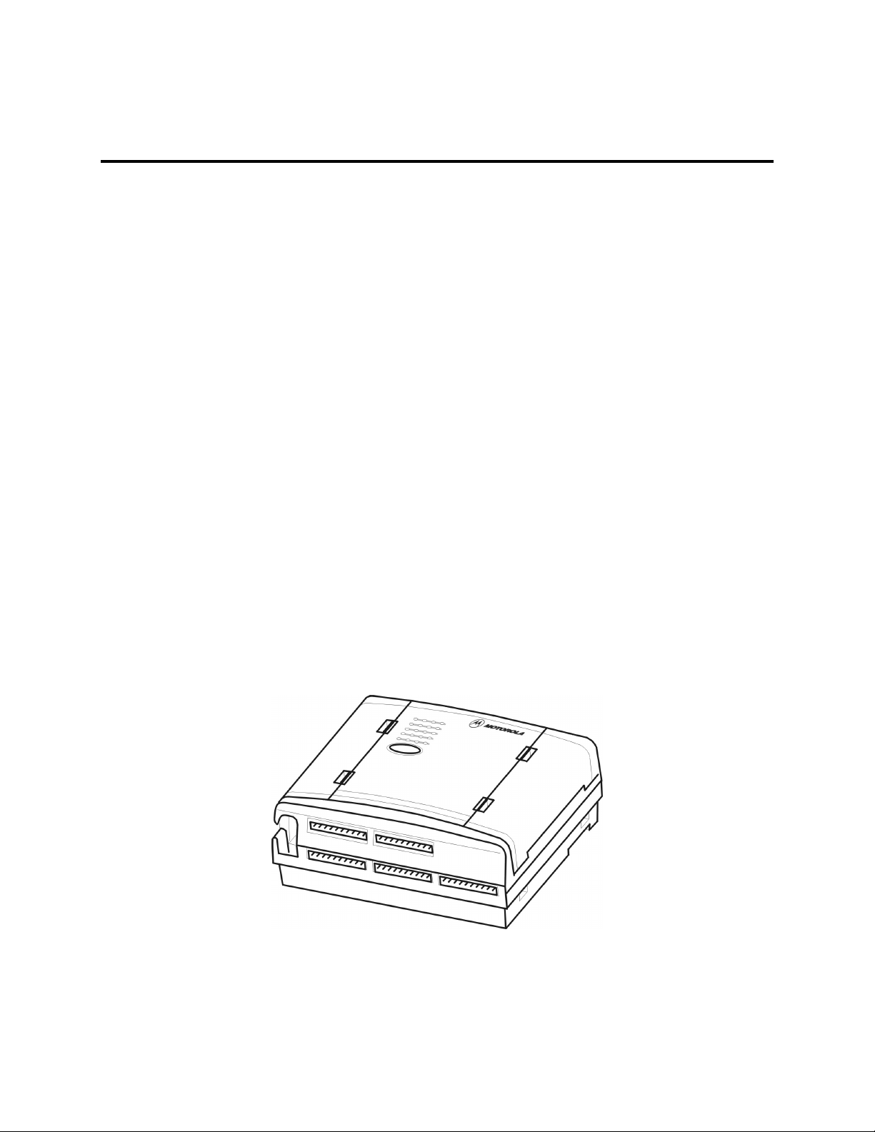
Figure 1 provides a general view of the MOSCAD-M RTU.
The MOSCAD-M RTU is enclosed in an indoor plastic case and is intended for outdoor base
station use. The installer must make sure that the installation meets the requirements of the
standard and protects the unit from weather hazards.
The antenna must be physically secured at a permanent outdoor location.
Figure 1
MOSCAD-M RTU –General View with Case
1

Hardware Options
Line, RS232 and RS485 Communication Interfaces
A variety of Line, RS232, and RS485 communication interfaces are available:
• RS485 adapter
• RS232 multiplexer
• Ethernet Interface Unit
Radio Communication Interfaces
A variety of radios can be attached using internal DPSK or duo-binary modem:
• Internal radio UHF High Band
• Internal radio UHF Low Band
• Variety of external radios (GP140/328, HT750, PRO5150)
For details on the available external radio models, and their connection to the RTU, see
Appendix B.
Introduction
I/O Configurations
Different models of the MOSCAD-M RTU have slightly different I/O configurations.
Models with basic I/O configuration:
• 12 Digital Input
• 8 Digital Output (4 Magnetically Latched, 4 Open Collector)
• 2 Digital Output (Solid State)
Models with expanded I/O configuration:
• 15 Digital Input
• 8 Digital Output (4 Magnetically Latched, 4 Open Collector)
• 4 Analog Input (4-20 mA)
• 1 Analog Output (0-5V or 4-20mA)
• 2 Digital Output (Solid State)
Power Supply and Battery
The power supply and backup battery options are:
• 9-30V DC power input (compatible with 12V DC Solar Panel)
• 3 x “C” backup battery (for Real Time Clock and RAM retention)
2
INSTALLATION
General
MOSCAD-M SAFETY SUMMARY
The MOSCAD-M should be installed by qualified and authorized
technicians. If the installation involves high-voltage connections,
technicians must be specifically qualified to handle high voltage.
This equipment was tested with cables 3 meters in length. If longer
cables and/or cabinets are used, the installer is responsible for making
sure that the installation complies with the requirements of the relevant
standard.
The product is a radio accessory. The installer must make sure that the
radio connected to the system has all required approvals and that the
installation meets the requirements of the standard. This equipment is a
base station unit and complies with the FCC base station requirements.
The antenna must be installed outdoors.
Power Connections:
This device accepts 9-30V DC input, maximum 2.5A @15V DC.
This chapter covers the following installation procedures:
• Wall mounting
• Connections
• Backup Batteries
• Miscellaneous
Wall Mounting
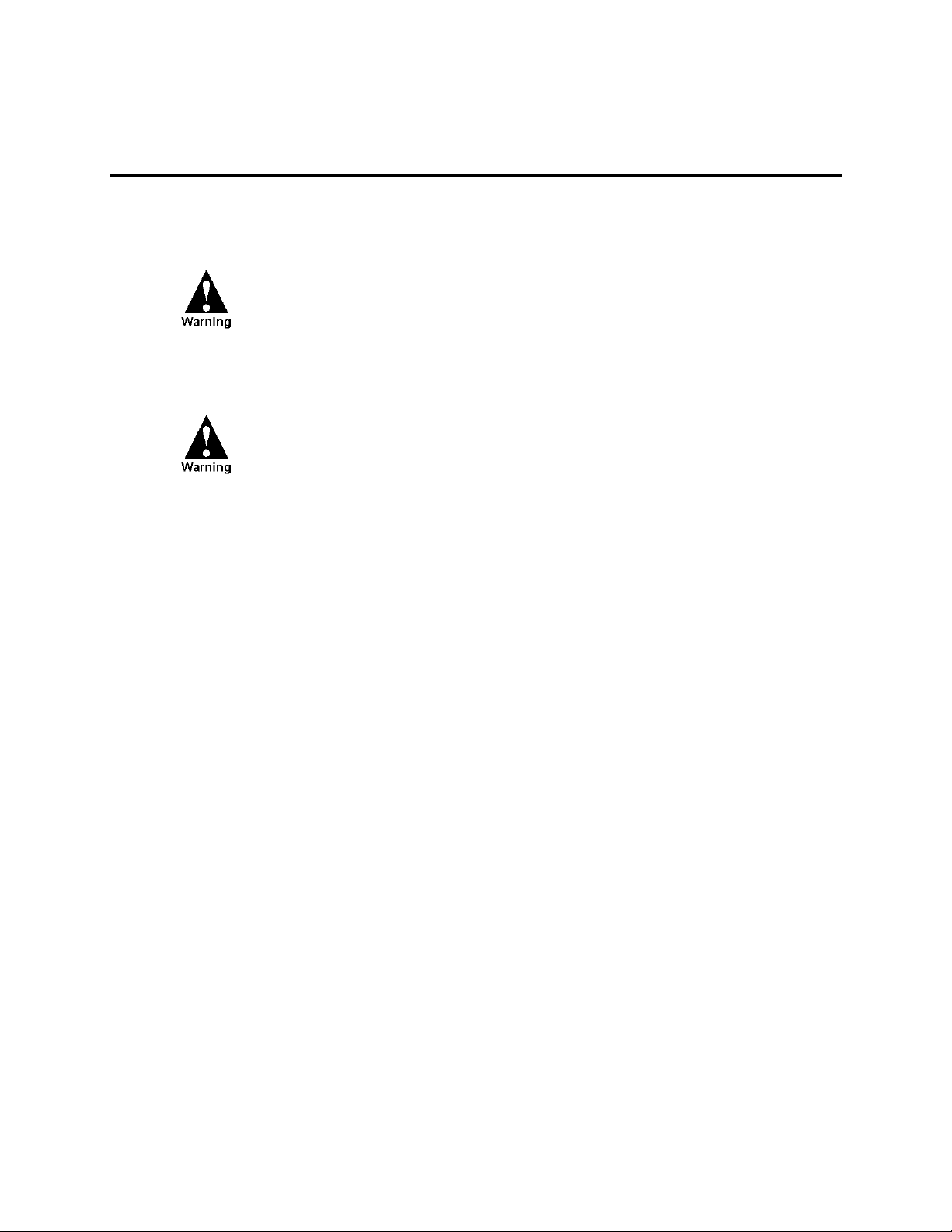
The dimensions of the unit are: width – 21.5 cm (8.46"), height – 18.5 cm (7.28"), depth – .85
cm (.33"), weight – 1.5kg maximum (see Figure 2).
3
Installation
Figure 2
Dimensions of MOSCAD
-M RTU Plastic Case
The unit can be installed on screws or on DIN rail mounting. Before installing the
MOSCAD-M RTU, verify that there is sufficient space around the unit. Allow 20 cm (7.87")
from the bottom of the box for the TB connectors. When an RF connector is attached (internal
radio models), allow for an extra 10 cm (4"): 2.02 cm (.8") from the top of the box for the RF
connector and 8 cm (3.15") for the wires. For models with external radios, allow 8 cm (3.15").
Wall Mounting with Screws
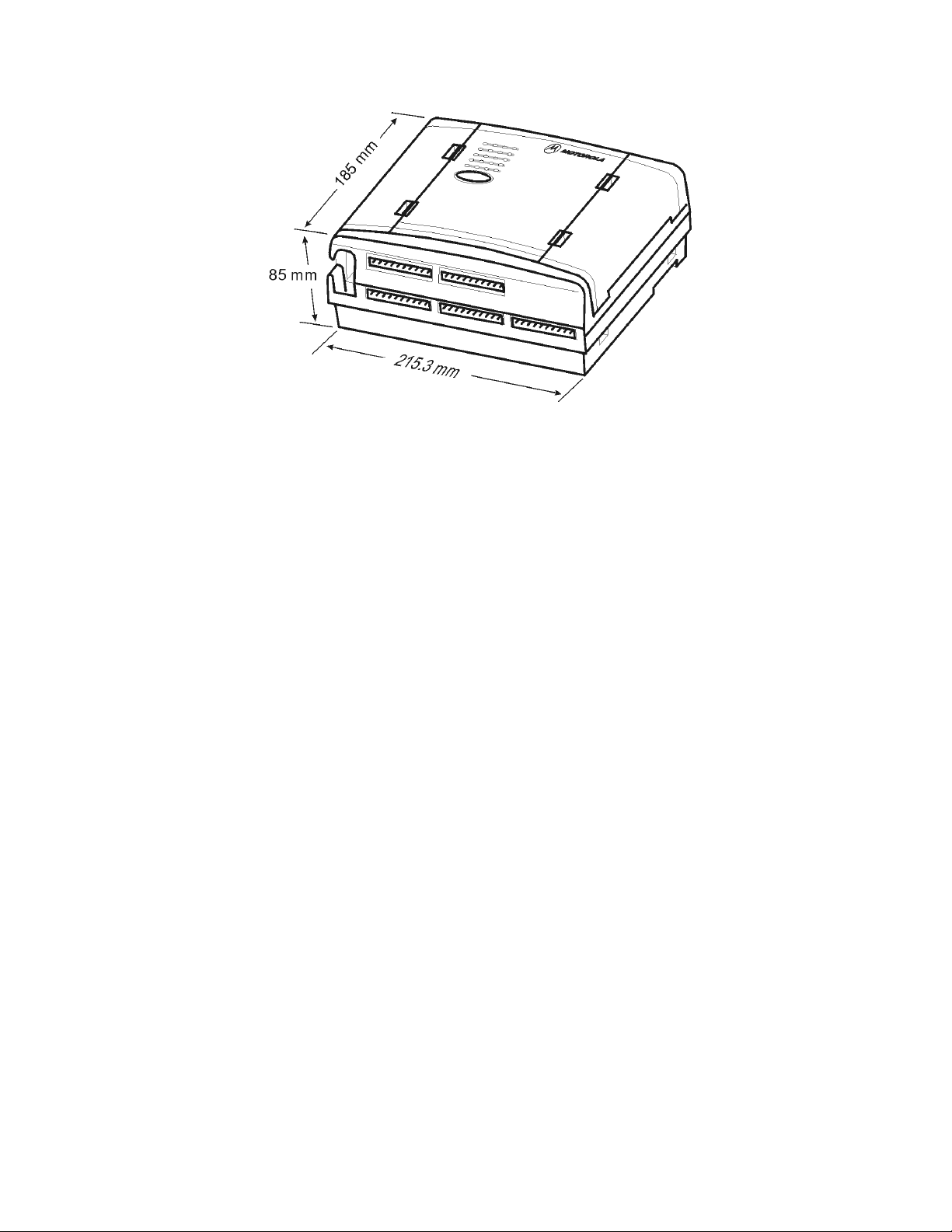
The MOSCAD-M can be mounted on the wall using screws, as shown in Figure 3.
1. Secure two screws (maximum head size 0.9 mm) on the wall, 105 mm apart.
2. Hang the unit on the screws, fitting the two cavities on the back cover of the unit over the
screws (see Figure 3).
The screws used should not protrude from the wall surface by more than 6 mm or by less than
4 mm.
4
Installation
Figure 3
Installation of MOSCAD
-M – Screw Mount
It is also possible to attach the MOSCAD-M to the wall using the small screw hole at the
bottom of case, though this requires dismantling the RTU, which is generally discouraged.
Consult Motorola service personnel before opening the MOSCAD-M casing. To mount the
RTU:
1. Open the case and dismantle the parts of the MOSCAD-M.
2. Secure the back of the case against the wall using a screw whose diameter is less than
3.5 mm and head size is at least 5.5 mm.
3. Reassemble the parts of the MOSCAD.
Before beginning any disassembly or reassembly procedures, you
should be adequately grounded to prevent damage to static sensitive
devices in the unit.
Wall Mounting on DIN Rail
For mounting the RTU on a DIN rail, two universal foot elements (Phoenix Connectors MFC
PIN UMK-FE) are required. To mount the unit, proceed as follows:
1. Slide the two foot elements into the recesses on the back cover of the unit as shown in
Figure 4. Press until they click behind the snaps that secure their placement. (See zoomed
image in Figure 5.)
5
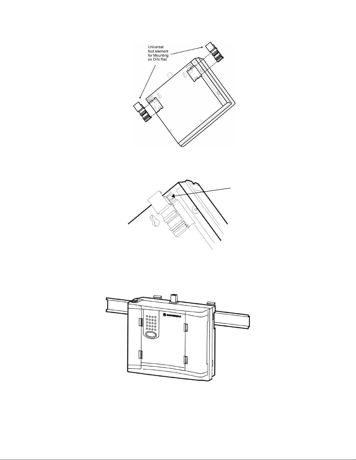
Figure 4
DIN Rail Attachment
Installation
SNAP
Figure 5
DIN Rail Attachment-Foot Element Snap-in (Enlarged)
2. Press the unit onto the DIN rail, using both universal foot elements. The elements can be
used on DIN rail 35 mm and G rails. (See Figure 6).
Figure 6
MOSCAD
-M Mounted on DIN Rail
6
Connections
Ground Connection
Connect the grounding cable directly to the protective
grounding pins 9 and 10 (PGND) in the main power-in connector
(see TB1 in Figure 9).
Power Connections
The unit can be connected directly to a 9-30V DC source through the main Power-In connector
(see Figure 9) where Pin #1 is + (positive) and Pin #2 is – (negative).
Installation
Verify that all power and ground connections are made in
accordance with local standards.
It is recommended to connect the main power supply to the unit
with a 3.5 amp fuse on the cable.
Backup Battery Connection
The RTU has a special chamber for 3 “C” alkaline backup batteries (not supplied) that are
used to retain the unit’s RAM and Real Time Clock in power fail situations.
Internal Radio Connection - antenna
The internal radio is connected through the 14-pin connector on the Main board inside the
plastic housing. Its power is driven from that connector. When an internal radio is installed,
Port 3 of the radio cannot be used.
External Radio Connection
Connect the external radio to Port 3 (see Figure 9). Verify that the radio button is set to ON.
The radio signals are driven from the AUX connector in Figure 9.
It is recommended to replace the external radio only when the
unit is powered off.
7

If the external radio is connected to an outside power supply,
first power on the unit, and then power on the radio.
The auxiliary power supply (maximum 2A) can be changed to 6V,
6.5V, 7.5V, 8V, 9V or 9.6V DC by changing the setting of the P11
jumper located on the Main board. (See markings on the board.) To
set the power to 8V, remove the jumper and save for future use.
This is usually set in the factory according to the external power
supply of the radio. The default setting is 9V DC. To change the
voltage, follow the disassembly instructions in Appendix C, place the
jumper and reassemble.
Line Communication Connection
Line Communications are connected through Ports 1 or 2 (see Figure 9.) Port 1 can be
programmed as RS485 (1A) or RS232 (1B). Port 2 can be programmed as RS232.
Installation
8
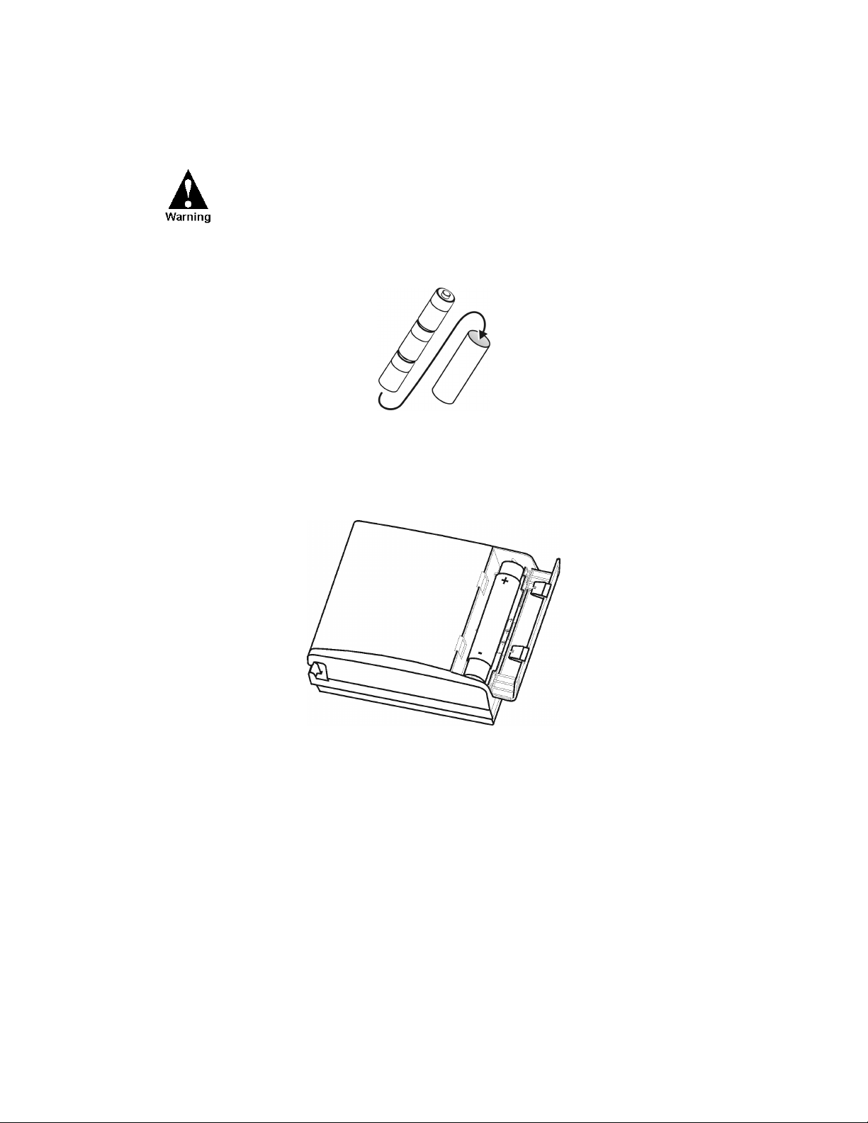
Installation of Backup Batteries
The backup battery should not be installed before the unit is
connected to the main power supply. This may cause the
battery to drain.
1. Place 3 “C” size alkaline batteries into the carton cylinder, each in the same direction, as
shown in Figure 7 below.
Figure 7
Backup Battery Cylinder and 3 Backup C Batteries
Installation
2. Place the cylinder with the batteries into the battery case in the direction indicated on the
unit (see Figure 8 below).
Figure 8
Installation of Backup Batteries
9

Miscellaneous
Open the Case Door
To open the case door properly, press the two clips (latches) and pull the wing to an open
position. The cable cover is opened counter-clockwise to expose the cable connections and
the backup battery cover is opened clockwise to expose the battery housing.
Close the Case Door
To close the case door properly, press until the latch clicks. Note that if the batteries in the
housing are not inserted properly, the backup battery cover door may not close. If the cable
connections are not threaded properly through the cable holes, the cable cover may not close.
Antenna Placement
The antenna is connected to the internal radio through the snap hole on top of the plastic
housing (see Figure 9). For models with external radios, screw the antenna onto the radio
antenna connector.
Installation
An antenna placed on top of the plastic housing produces
strong electromagnetic fields that could be harmful to the
electronics of the MOSCAD-M RTU and to people in the vicinity.
Fixed Site Antennas
The antenna installation must comply with the following requirements in order to assure
optimal performance and make sure human exposure to radio frequency electromagnetic
energy is within the guidelines set forth by the local regulations.
• The antenna must be mounted outside the building.
• Mount the antenna on a tower if at all possible.
• If the antenna is to be mounted on a building, then it must be mounted on the roof.
• As with all fixed site antenna installations, it is the responsibility of the licensee to manage
the site in accordance with applicable regulatory requirements. This may require
additional compliance actions such as site survey measurements, signage, and site access
restrictions in order to ensure that exposure limits are not exceeded.
10
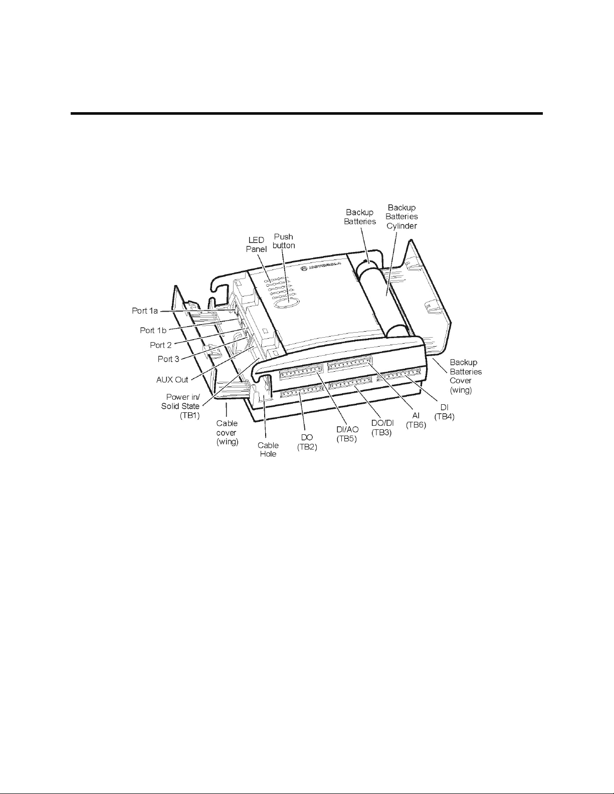
THE MOSCAD-M UNIT
Overview
The MOSCAD-M RTU (shown below) contains power connections, line communication ports,
internal/external radio interfaces, radio modems and I/Os.
Figure 9
MOSCAD
-M Unit
11

Communication Ports
The MOSCAD-M RTU has 3 ports available:
PORT 1 - RS232 Configurator Port (for programming and monitoring the unit), RS232
External Dialup Modem, or RS485 Communication, User protocol
(1A is used for RS485)
(1B is used for RS232)
PORT 2 – Secondary Port RS232 (User protocol)
PORT 3 – External Radio interface
Ports 2 and 3 can work simultaneously with each other and with either Port 1A or Port 1B.
Ports 1A and 1B cannot work simultaneously. Port 3 cannot be used when an internal radio is
installed.
Connectors
The MOSCAD-M RTU has the following connectors available (see Figure 9):
RS485 Port 1A (RJ45, 4 pin)
The MOSCAD-M Unit
RS232 Port 1B (RJ45, 8 pin)
RS232 Port 2 (RJ45, 8 pin)
External Radio Port 3 (RJ45, 8 pin)
AUX out for external radio power supply (2 pin)
Power In/Solid State DO (10 pin) - TB1
DO (10 pin) – TB2
DO/DI (10 pin) – TB3
DI (10 pin) – TB4
DI/AO (10 pin) – TB5
AI (10 pin) - TB6
The MOSCAD-M RTU has the following internal connectors.
Internal radio connector (14 pin)
Backup Battery connector (2 pin)
I/O Expansion connector (26 pin)
Controls and Indicators
The push-button is used to activate the LED panel, to toggle the LED panel so that it displays
the status of the CPU or of the I/Os, to initiate software downloading to the CPU, and to erase
User Flash memory and RAM.
12

LED Control
Display On/Advance
When the display is off, pressing the push-button once, momentarily, activates the display.
Every consecutive momentary depression of the push-button advances the display to the next
page, in the following order: CPU > IO1 (I/O Page 1-DI) > IO2 (I/O Page 2-DO) > IO3
(I/O Page 3-AI) > Page 4 (AO) > Page 5 (User Application Controlled) > Page 6 (Hardware
Test Controlled). The next depression of the push-button returns the display to the CPU.
Display Off
The display can be programmed using the Configurator Site Configuration tool to turn off
automatically after a predefined period of time if the push-button has not been pressed.
LED Test
When the push-button is pressed continuously for a few seconds, all LEDs light up
simultaneously. When the push-button is released, the LEDs turn off.
User Flash Erase
After power-up, all LEDs light up. To erase the User Flash, press the push-button while the
LEDs are lit. All the LEDs flash three times. Now, release the push-button.
The MOSCAD-M Unit
Alternatively, press the push-button continuously for at least 40 seconds at any time to erase
the User Flash.
User RAM Erase (Cold Restart)
Turn off the power supply, while the push-button is depressed. The next time the unit is
powered up, it will perform “cold restart”, which means all data stored in the RAM is erased.
Note: The data that is stored in the Flash (i.e. applications, site configuration, and network
configuration) will not be erased.
System Software Downloading
During power up, press the push-button continuously. This will cause the unit to enter
bootstrap downloading mode, in which the FLASH is programmed from a PC connected to
Port 1 of the MOSCAD-M. The CPU LED will begin to blink at 1 Hz, indicating that the CPU
has entered bootstrap downloading mode. If after 120 seconds no bootstrap software is loaded
and executed, the normal power-up procedure is performed.
CPU Reset
To reset the CPU when a backup battery is not installed, turn the power supply to the unit off
and on again. When a backup battery is installed, follow the Cold Restart method described
above.
13
 Loading...