

Page 1

APPLICANT: MOTOROLA SOLUTIONS EQUIPMENT TYPE: ABZ89FC5827
109AB-5827
User Information
User Information
Tune-up and user / operational manual information are provided in the following exhibits.
EXHIBIT DESCRIPTION
D1 Tune-Up Procedure
D2 User / Operational Manual
EXHIBIT D
Page 2

APPLICANT: MOTOROLA SOLUTIONS EQUIPMENT TYPE: ABZ89FC5827
109AB-5827
User Information
Tune-Up Procedure
Aside from the 3
rd
party cavity combiners, there is no field tune-up procedure. All adjustments are software
controlled and are pre-set at the factory. Certain station operating parameters can be changed via man-machine
interface (MMI) commands, within predetermined limits. Examples include transmit / receive operating frequencies
and transmitter power level.
For information on tuning the cavity combiners, which is required only if replaced in the field, please refer to the
User / Operational Manual.
EXHIBIT D1
Page 3

APPLICANT: MOTOROLA SOLUTIONS EQUIPMENT TYPE: ABZ89FC5827
109AB-5827
User Information
Operational or User’s Manual
The manual should include instruction, installation, operator, or technical manuals with required ‘information to the
users’. This manual should include a statement that cautions the user that changes or modifications not expressly
approved by the party responsible for compliance could void the user’s authority to operate the equipment. The
manual shall include RF Hazard warning statements, if applicable.
This product is installed in restricted access locations only, thus only authorized service personnel have access to
the product. As such, a high level User’s Installation / Operating instruction manual for the product is not
published.
Content from the document “MTS LITE, MTS 2 AND MTS 4 INSTALLATION, CONFIGURATION AND
BASIC SERVICE MANUAL” (part number 6802800U74-AD, September 2014) has been included as part of this
filing package.
Due to space constraints, the full electronic version of this manual is not included in its entirety. The following
chapters have been removed from the full document as these chapters are not intended for the general ‘user’:
Chapter 3: Site Preparation
Chapter 4: Hardware Installation
Chapter 5: Interconnection and Internal Cabling
Chapter 6: Configuration and Testing
Chapter 13: MTS Troubleshooting
Upon request, published manuals will be sent to the commission and/or telecommunication certification body
(TCB). All of the descriptions, block diagrams, and schematics that are included in this filing package are current
as of the package submittal date.
EXHIBIT D2
Page 4

™
Applicant: Motorola Solutions
Equipment Type: ABZ89FC5827 / 109AB-5827
Exhibit D2
DIMETRA
Dimetra IP Scalable (DIPS)
Dimetra IP Compact (DIPC)/Scalable Dimetra IP (SDIP)
Dimetra IP Micro/Dimetra IP LiTE
MTS LITE, MTS 2 AND MTS
4 INSTALLATION,
CONFIGURATION AND
BASIC SERVICE MANUAL
©
2014 Motorola Solutions, Inc. All rights reserved
September 2014
*6802800U74*
6802800U74-AD
Page 5

Applicant: Motorola Solutions
Equipment Type: ABZ89FC5827 / 109AB-5827
Exhibit D2
Page 6

Copyrights
Applicant: Motorola Solutions
Equipment Type: ABZ89FC5827 / 109AB-5827
Exhibit D2
The Motorola products described in this document may include copyrighted Motorola computer programs. Laws in
the United States and other countries preserve for Motorola certain exclusive rights for copyrighted computer
programs. Accordingly, any copyrighted Motorola computer programs contained in the Motorola products described
in this document may not be copied or reproduced in any manner without the express written permission of Motorola.
©
2014 Motorola Solutions, Inc. All Rights Reserved
No part of this document may be reproduced, transmitted, stored in a retrieval system, or translated into any language
or computer language, in any form or by any means, without the prior written permission of Motorola Solutions, Inc.
Furthermore, the purchase of Motorola products shall not be deemed to grant either directly or by implication,
estoppel or otherwise, any license under the copyrights, patents or patent applications of Motorola, except for the
normal non-exclusive, royalty-free license to use that arises by operation of law in the sale of a product.
Disclaimer
Please note that certain features, facilities, and capabilities described in this document may not be applicable to or
licensed for use on a particular system, or may be dependent upon the characteristics of a particular mobile subscriber
unit or configuration of certain parameters. Please refer to your Motorola contact for further information.
3 | Copyrights
Trademarks
MOTOROLA, MOTO, MOTOROLA SOLUTIONS, and the Stylized M Logo are trademarks or registered
trademarks of Motorola Trademark Holdings, LLC and are used under license. All other trademarks are the property
of their respective owners.
European Union (EU) Waste of Electrical and Electronic Equipment (WEEE)
directive
The European Union's WEEE directive requires that products sold into EU countries must have the crossed out
trash bin label on the product (or the package in some cases).
As defined by the WEEE directive, this cross-out trash bin label means that customers and end-users in EU countries
should not dispose of electronic and electrical equipment or accessories in household waste.
Customers or end-users in EU countries should contact their local equipment supplier representative or service centre
for information about the waste collection system in their country.
6802800U74-AD | September 2014 | Send Feedback
Page 7

Applicant: Motorola Solutions
Equipment Type: ABZ89FC5827 / 109AB-5827
Exhibit D2
Page 8
5 | CMM Labeling and Disclosure Table
Applicant: Motorola Solutions
Equipment Type: ABZ89FC5827 / 109AB-5827
Exhibit D2
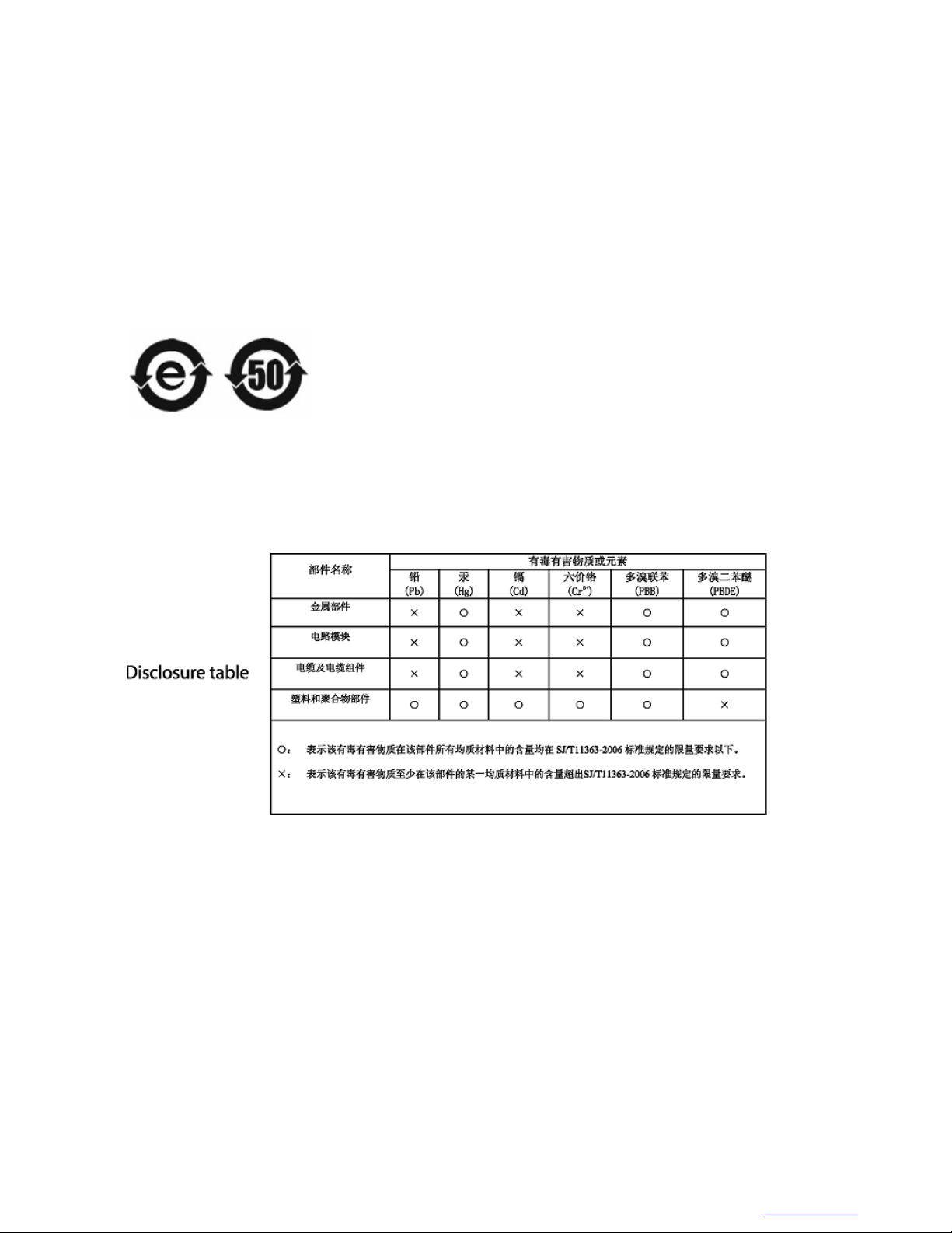
CMM Labeling and Disclosure Table
The People’s Republic of China requires that our products comply with China Management Methods (CMM)
environmental regulations. (China Management Methods refers to the Regulation Management Methods for
Controlling Pollution by Electronic Information Products.) Two items are used to demonstrate compliance; the Label
and the Disclosure Table.
The label is placed in a customer visible position on the product. The first of the following examples means that the
product contains no hazardous substances; the second means that the product contains hazardous substances, and has
an Environmental Friendly Use Period (EFUP) of fifty years.
The Environmental Friendly Use Period (EFUP) is the period (in years) during which the Toxic and Hazardous
Substances (T&HS) contained in the Electronic Information Product (EIP) will not leak or mutate causing
environmental pollution, or bodily injury from the use of the EIP.
The Disclosure Table, printed in simplified Chinese, is included with each customer order. An example of a
Disclosure Table (in Chinese) follows:
6802800U74-AD | September 2014 | Send Feedback
Page 9

Applicant: Motorola Solutions
Equipment Type: ABZ89FC5827 / 109AB-5827
Exhibit D2
Page 10

7 | Service Information
Applicant: Motorola Solutions
Equipment Type: ABZ89FC5827 / 109AB-5827
Exhibit D2
Service Information
Government Technical Support (GTS), EA Solutions Support Centre
The Government Technical Support (GTS), EA Solutions Support Centre provides a remote Technical Support
Service to help customers resolve technical issues and quickly restore networks and systems. This team of highly
skilled professionals is available to customers with current service agreements in place that include the Technical
Support Service. The EA GTS technical experts may be accessed through the EMEA Integrated Call Center either
electronically or using the telephone numbers listed below. If you are unsure whether your current service agreement
entitles you to benefit from this service, or if you would like more information about the Technical Support Service,
contact your local customer support or account manager for further information.
Contact Details
Email: essc@motorolasolutions.com
Table 1: List of Telephone Numbers
Country In Country Number to Dial
AUSTRIA 01206091087
DENMARK 043682114
FRANCE 0157323434
GERMANY 06950070204
ITALY 0291483230
LITHUANIA 880 030 828
NETHERLANDS 0202061404
NORWAY 24159815
PORTUGAL 0217616160
RUSSIA 810 800 228 41044
(Alternative 810 800 120 1011)
SAUDI ARABIA 800 844 5345
SOUTH AFRICA 0800981900
SPAIN 0912754787
UNITED KINGDOM 02030 277499
All Other Countries +44 2030 277499
European Systems Component Centre (ESCC)
The European Systems Component Centre provides a repair service for infrastructure equipment. Customers requiring
repair service should contact the Customer Information Desk to obtain a Return Material Authorization number. The
equipment should then be shipped to the following address unless advised otherwise.
Motorola GmbH, European Systems Component Centre, Am Borsigturm 130,13507 Berlin, Germany
Contact Details
• E-Mail: escc.admin@motorolasolutions.com
6802800U74-AD
| September 2014 |
Send Feedback
Page 11

8 | Service Information
Applicant: Motorola Solutions
Equipment Type: ABZ89FC5827 / 109AB-5827
Exhibit D2
• Telephone: +49 (0) 30 66861404
• Telefax: +49 (0) 30 66861426
• Monday – Friday 08:00 am to 06:00 pm (CET)
Parts Identification and Ordering
Request for help in identification of non-referenced spare parts should be directed to the Customer Care Organization
of Motorola’s local area representation. Orders for replacement parts, kits, and assemblies should be placed directly
on Motorola’s local distribution organization or through the Extranet site Motorola Online at https://
emeaonline.motorolasolutions.com.
Updated Versions of Manuals
Verify the current version of the manual at our Extranet site, Motorola Online: https://
emeaonline.motorolasolutions.com.
Your Input
Send questions and comments regarding user documentation to documentation@motorolasolutions.com
We welcome your feedback on this and other Motorola manuals. To take a short, confidential survey on Motorola
Customer Documentation, go to docsurvey.motorolasolutions.com
device to access the survey.
or scan the following QR code with your mobile
Send Feedback | September 2014 | 6802800U74-AD
Page 12

Document History
Applicant: Motorola Solutions
Equipment Type: ABZ89FC5827 / 109AB-5827
Exhibit D2
Version Description Date
6802800U74–A Initial Edition July 2006
6802800U74–B Minor changes Aug. 2006
6802800U74–C Table 4–4 updated Aug. 2006
Table 4–5 updated and note inserted
Table 5–6 updated
6802800U74–D Service Cable and Connector Box Description section updated Oct. 2006
6802800U74–E Updates throughout the manual Feb. 2007
9 | Document History
6802800U74–F Expansion Cabinet updates throughout the manual, and addi-
tion of Expansion Options chapter.
6802800U74–G 800 MHz updates throughout the manual. Nov. 2007
6802800U74–H BTS Q108 SPU updates, including the addition of redundant
power connector on the Site Controller.
6802800U74–J
6802800U74–K
6802800U74–L
• Regulatory CE Labeling Compliance updated
• MTS 4 Outdoor Enclosure on page 403 added
• Added info about Base Radio dekey when Standby SC is
powered on.
• Added info about frequencies in receiver band that can
cause high bit error rate to occur
• Updated FRU number for RX Splitter
Updated MTS site link configuration info in Table 8–9
•
• Updated RF cabling/Connections for MTS 4 with two
TX/RX antennas and up to one additional RX antenna (Table 5–13 and Figure 5–12)
• Revision to FRU numbers for MTS fan and Hybrid
Combiner
• Other minor updates
• Updated manual with TEDS compatibility.
• Updates to the Power Supply Unit (PSU) DC Input Power.
• Other minor updates throughout the manual.
Aug. 2007
Mar. 2008
June 2008
Dec. 2008
Apr. 2009
6802800U74–M
6802800U74–N
6802800U74–P Updated the following sections: July 2010
• Ethernet Site Link Cabling hardware installation informa-
• Ethernet Site Link cabling and interconnection added.
• Configuring Ethernet Site Link added.
• Ethernet Site Link Retro-fit kit and configurations added.
• Added section MTS LVD Kit Installation to Hardware In-
June 2009
tion added.
Sep. 2009
stallation chapter.
Table continued…
6802800U74-AD | September 2014 | Send Feedback
Page 13

10 | Document History
Applicant: Motorola Solutions
Equipment Type: ABZ89FC5827 / 109AB-5827
Exhibit D2
Version Description Date
• 260 MHz additions throughout the manual.
• Updated information on LVD Kit Installation
• Updated MTS 4 Duplexer FB diagram
Updated procedure How to configure E1 links
•
• other minor updates
6802800U74–R Added non-duplexed MTS 2 configurations Sep. 2010
6802800U74–T Added MTS LiTE Dec. 2010
6802800U74–U
6802800U74–V
6802800U74–W Updated the following:
• Added Procedure How to Upgrade the ATCC Firmware
• Updated Procedure How to Replace Site Controller Lithium
Battery
• Added section Tuning the MTCC in a BTS in Tetra Applica-
tion Mode on page 256
• Removed reference to obsolete item (surge arrestor for an
MTS4 in 450 MHz band for TX/RX and/or RX antennas)
• Added warning not to key the base station without a proper
load
• Added New part numbers for duplexer and preselector (supplied by Fingu, replaces Power Wave)
• General Defect Fixing
• MMI Commands and MTS Modes of Operation on page
203
• Table 41: RF Cabling/Connections for MTS LiTE with One
TX and One RX ant. No Diversity on page 162
• Service Cable and Connector Box Description on page 207
• Setting Base Radio IP on page 217
Station Verification Procedures on page 220
• Added Configuring the Base Radio VSWR on page 220
• Configuring the Base Radio Receiver on page 217
• XHUB Controller – Front Panel Indicators (LED) on page
282
• XHUB Controller – Front Panel Connectors on page 284
• Troubleshooting: General Check of a Site Controller File
on page 318
• Added Ethernet Site Link on page 328.
• Base Radio Alarms on page 333
• Miscellaneous Troubleshooting on page 355
• Field Replaceable Units (FRUs) on page 405
June 2011
Mar. 2012
May 2012
Restoration content moved to the respective Backup And Re-
store Including FRU/FRE manuals (for Dimetra IP Scalable
and Dimetra IP Compact systems) or Service Manual (for Dimetra IP Micro system).
6802800U74–Y
Send Feedback | September 2014 | 6802800U74-AD
Added:
Dec.2012
Table continued…
Page 14

Document History | 11
Applicant: Motorola Solutions
Equipment Type: ABZ89FC5827 / 109AB-5827
Exhibit D2
Version Description Date
• Verifying and Tuning the Receiver RSSI Levels on page
224
Updated:
• Ethernet Site Link on page 328
• Site Controller – Front Panel Indicators (LED)
267
on page
6802800U74–AA
6802800U74–AB Updated the following:
6802800U74–AC Updated:
6802800U74–AD Added:
Added:
• Encrypted Ethernet Site Links on page 331
• Verifying Encryption Capability on page 332
Updated:
• Verifying and Tuning the Receiver RSSI Levels on page
224
• Encrypted Ethernet Site Links on page 331
• Verifying Encryption Capability on page 332
• Field Replaceable Units for MTS LiTE on page 405
• Field Replaceable Units for MTS 2 on page 407
• Field Replaceable Units for MTS 4 on page 409
• Miscellaneous Troubleshooting on page 355
• RF Cabling – MTS 4, No Diversity on page 172
• Resetting the RTC Battery Status on page 275
Updated:
Feb. 2013
Mar. 2014
July 2014
Sept. 2014
• Checking if the Site Controller Lithium Battery Needs
• Replacing the Site Controller Lithium Battery on page 276
Changing on page 276
6802800U74-AD | September 2014 | Send Feedback
Page 15

Applicant: Motorola Solutions
Equipment Type: ABZ89FC5827 / 109AB-5827
Exhibit D2
Page 16

Contents
Applicant: Motorola Solutions
Equipment Type: ABZ89FC5827 / 109AB-5827
Exhibit D2
Copyrights........................................................................................................................................ 3
CMM Labeling and Disclosure Table............................................................................................5
Service Information......................................................................................................................... 7
Document History............................................................................................................................9
List of Figures................................................................................................................................ 23
List of Tables.................................................................................................................................. 29
List of Processes............................................................................................................................. 33
List of Procedures.......................................................................................................................... 35
About MTS LiTE, MTS 2 and MTS 4 Installation, Configuration and Basic Service
Manual....................................................................................................................................... 37
What Is Covered In This Manual?...................................................................................................................... 37
Helpful Background Information
Related Information.............................................................................................................................................37
Icon Conventions.................................................................................................................................................38
Style Conventions................................................................................................................................................39
Regulatory CE Marking Compliance..................................................................................................................39
........................................................................................................................ 37
Contents | 13
Chapter 1: MTS Overview.................................................................................... 41
MTS Platform Description.................................................................................................................................. 41
MTS LiTE Components...................................................................................................................................... 42
MTS 2 Components............................................................................................................................................ 43
MTS 4 Components............................................................................................................................................ 45
Expansion Cabinet Components......................................................................................................................... 46
MTS Modules......................................................................................................................................................47
RF Distribution System...........................................................................................................................47
Preselector................................................................................................................................... 47
Duplexer...................................................................................................................................... 48
Post Filter.................................................................................................................................... 48
Cavity Combiners........................................................................................................................48
Hybrid Combiner.........................................................................................................................49
Rx Splitter....................................................................................................................................49
Site Controller Module............................................................................................................................49
XHUB......................................................................................................................................................49
Base Radio Module................................................................................................................................. 50
Base Radio Transceiver...............................................................................................................50
Base Radio Power Amplifier.......................................................................................................50
Power Supply Unit.................................................................................................................................. 50
Backup Battery............................................................................................................................50
Cooling Fans........................................................................................................................................... 50
Chapter 2: General Safety.....................................................................................51
General Safety Precautions................................................................................................................................. 51
Mains Safety........................................................................................................................................................52
Battery Safety......................................................................................................................................................52
Chapter 3: Site Preparation.................................................................................. 55
Page 17

14 | Contents
Applicant: Motorola Solutions
Equipment Type: ABZ89FC5827 / 109AB-5827
Exhibit D2
Site Planning........................................................................................................................................................55
Site Survey.............................................................................................................................................. 55
Site Selection Considerations..................................................................................................................56
Cabinets Installation Considerations
MTS LiTE Cabinet Considerations.........................................................................................................56
MTS 2 Cabinet Considerations............................................................................................................... 58
MTS 4 Cabinet Considerations............................................................................................................... 59
Expansion Cabinet Considerations..........................................................................................................61
Antenna Installation Considerations................................................................................................................... 63
Network Interface Installation Considerations....................................................................................................64
MTS Installation Special Considerations............................................................................................................64
Environmental Considerations............................................................................................................................ 64
MTS Installation Electrical Requirements for MTS Site.................................................................................... 65
Applicable Codes and Practices.............................................................................................................. 65
AC and DC Power Supplies.................................................................................................................... 66
Service Current Rating................................................................................................................ 66
AC and DC Current Load............................................................................................................72
Backup Battery............................................................................................................................72
Surge Arrestors........................................................................................................................................72
Power Panel.............................................................................................................................................72
User Alarms, Control Outputs, and Door Alarm.................................................................................................73
Grounding Requirements.................................................................................................................................... 73
...................................................................................................................56
Chapter 4: Hardware Installation........................................................................ 75
Installation Overview.......................................................................................................................................... 75
Installation Personnel.............................................................................................................................. 75
Receiving the MTS Equipment............................................................................................................... 75
Installation Prerequisites..................................................................................................................................... 76
Cabinet Transportation........................................................................................................................................76
Safety Considerations..............................................................................................................................77
MTS LiTE and MTS 2 Cabinets Transportation.....................................................................................77
Moving the MTS 4 and Expansion Cabinet............................................................................................ 77
Cabinet Installation..............................................................................................................................................79
Cabinet Bracing Considerations..............................................................................................................80
Floor Mounting Instructions....................................................................................................................80
Installing the Cabinet Using the Mounting Brackets.............................................................................. 80
Installing the Cabinet Using the Mounting Plate.................................................................................... 82
Mounting Plate............................................................................................................................ 82
Installing the Mounting Plate...................................................................................................... 83
Securing Cabinet to a Mounting Plate.........................................................................................84
Wall Fixing..............................................................................................................................................85
Electrical Connections.........................................................................................................................................86
Grounding Connection............................................................................................................................ 86
Grounding the Equipment Cabinet..........................................................................................................88
Battery System Grounding.......................................................................................................... 89
Checking Grounding Connections.............................................................................................. 89
Power Supply Connections..................................................................................................................... 89
-48 VDC Input Power and Backup Battery Charging Connections............................................89
Connecting -48 VDC Power Source to the Equipment Cabinet................................................. 91
100–240 VAC Input Power Connections....................................................................................93
Connecting 100–240 VAC Power Source to Equipment Cabinet...............................................95
Backup Battery Sensor Connections........................................................................................... 96
Connecting the Backup Battery Sensor to the Equipment Cabinet.............................................97
MTS LVD Kit Installation.......................................................................................................... 98
Installing the MTS LVD Kit..................................................................................................... 100
Page 18

Contents | 15
Applicant: Motorola Solutions
Equipment Type: ABZ89FC5827 / 109AB-5827
Exhibit D2
RF Antenna Connections...................................................................................................................................102
Expansion Cabinet Connections........................................................................................................................106
TX Connections.....................................................................................................................................106
Connections between Site Controller and XHUB Controller...............................................................
Power Connection to the XHUB Controllers........................................................................................108
CAN Bus Cabling..................................................................................................................................109
RX Connection......................................................................................................................................109
GPS Connections...............................................................................................................................................110
GPS Site Reference Operation Modes.................................................................................................. 111
Tracking Criteria................................................................................................................................... 112
GPS Start Up......................................................................................................................................... 112
Remote GPS Antenna/Receiver Connection.........................................................................................113
Remote GPS Receiver Requirements........................................................................................114
Remote GPS Receiver Cabling................................................................................................. 114
GPS Antenna Connection......................................................................................................................116
GPS Antenna Line Loss............................................................................................................ 118
GPS Interference Avoidance................................................................................................................. 118
X.21, E1-120Ω Cabling.....................................................................................................................................118
Ethernet Site Link Cabling................................................................................................................................121
Ethernet Site Link Retrofit Kit.............................................................................................................. 122
Connecting Ethernet Site Link Retrofit Kit for MTS 2 (old JP)............................................... 123
Connecting Ethernet Site Link Retrofit Kit for MTS 2 (new JP)..............................................123
Connecting Ethernet Site Link Retrofit Kit for MTS 4.............................................................123
Connecting Ethernet Site Link Retrofit Kit for MTS 4 with Expansion Cabinet (old JP)........124
Connecting Ethernet Site Link Retrofit Kit for MTS 4 with Expansion Cabinet (new JP)...... 124
External Alarm Cabling.....................................................................................................................................124
Performing a Final Check-Out after Installation...............................................................................................127
Checking the Cabinet after Setup..........................................................................................................127
Powering Up the MTS...........................................................................................................................127
Recommended Installation Tools, Parts, and Test Equipment..........................................................................127
Recommended Installation Tools..........................................................................................................128
Recommended Test Equipment.............................................................................................................128
Recommended Parts..............................................................................................................................129
Recommended Torque.......................................................................................................................... 130
Mounting Screws...................................................................................................................................130
107
Chapter 5: Interconnection and Internal Cabling............................................ 135
AC/DC Power Cabling......................................................................................................................................135
AC/DC Power Cabling – MTS LiTE.................................................................................................... 135
AC/DC Power Cabling – MTS 2...........................................................................................................136
AC/DC Power Cabling – MTS 4...........................................................................................................137
AC/DC Power Cabling – Expansion Cabinet........................................................................................140
User Alarms/Controls, X.21, RGPS, and GPS Cabling.................................................................................... 141
User Alarms/Controls, X.21, RGPS, and GPS Cabling – MTS LiTE.................................................. 142
User Alarms/Controls, X.21, RGPS, and GPS Cabling – MTS 2.........................................................143
User Alarms/Controls, X.21, RGPS, and GPS Cabling –MTS 4..........................................................144
E1 and Ethernet Cabling....................................................................................................................................147
E1 and Ethernet Cabling – MTS LiTE..................................................................................................147
E1 and Ethernet Cabling – MTS 2........................................................................................................ 148
E1 and Ethernet Cabling – MTS 4........................................................................................................ 149
E1 and Ethernet Cabling – Expansion Cabinet..................................................................................... 151
Ethernet Site Link Cabling................................................................................................................................152
Ethernet Site Link Cabling – MTS LiTE.............................................................................................. 153
Ethernet Site Link Cabling – MTS 2.....................................................................................................153
Ethernet Site Link Cabling – MTS 4 with Single Site Controller.........................................................154
Page 19

16 | Contents
Applicant: Motorola Solutions
Equipment Type: ABZ89FC5827 / 109AB-5827
Exhibit D2
Ethernet Site Link Cabling – MTS 4 with Dual Site Controller........................................................... 157
Ethernet Site Link Cabling – MTS 4 Expansion Cabinet with Single Site Controller......................... 159
Ethernet Site Link Cabling – MTS 4 Expansion Cabinet with Dual Site Controller............................
RF Cabling........................................................................................................................................................ 162
RF Cabling – MTS LiTE with One TX and One RX Antenna, No Diversity...................................... 162
RF Cabling – MTS LiTE with One TX/RX Antenna........................................................................... 163
RF Cabling – MTS LiTE with One TX and Two RX Antennas...........................................................164
RF Cabling – MTS 2, No Diversity...................................................................................................... 165
RF Cabling – MTS 2 with One TX Antenna.........................................................................................166
RF Cabling – MTS 2 with One TX/RX Antenna..................................................................................168
RF Cabling – MTS 2 with Two TX/RX Antennas................................................................................170
RF Cabling – MTS 4, No Diversity...................................................................................................... 172
RF Cabling – MTS 4 with One TX/RX Antenna..................................................................................174
RF Cabling – MTS 4 with Two TX/RX Antennas................................................................................176
RF Cabling – MTS 4 with One TX Antenna.........................................................................................178
RF Cabling – Expansion Cabinet with One TX/RX Antenna...............................................................180
RF Cabling – Expansion Cabinet with Two TX/RX Antennas.............................................................184
RF Cabling – Expansion Cabinet with One TX Antenna..................................................................... 187
RF Cabling – Expansion Cabinet with Two TX Antennas................................................................... 190
CAN Bus Cabling..............................................................................................................................................193
CAN Bus Cabling – MTS LiTE ...........................................................................................................193
CAN Bus Cabling – MTS 2.................................................................................................................. 193
CAN Bus Cabling – MTS 4.................................................................................................................. 195
CAN Bus Cabling – Expansion Cabinet............................................................................................... 199
160
Chapter 6: Configuration and Testing...............................................................203
Setup and Testing Overview............................................................................................................................. 203
Preparing for Configuration and Testing...........................................................................................................203
MMI Commands and MTS Modes of Operation.................................................................................. 203
Logging on to the Site Controller Application through Serial Connection...............................204
Logging on to the Base Radio Application through Serial Connection....................................204
Logging on to the BOOT1 mode...............................................................................................205
Logging on to the Test Application...........................................................................................205
Test Equipment......................................................................................................................................206
Service Cable and Connector Box Description.....................................................................................207
Setting Up Service Terminal................................................................................................................. 209
CAN Bus Configuration....................................................................................................................................209
PSU CAN Bus Commands....................................................................................................................209
Fans CAN Bus Commands................................................................................................................... 210
DPM CAN Bus Commands.................................................................................................................. 210
ATCC CAN Bus Commands................................................................................................................ 211
Other CAN Bus Commands..................................................................................................................211
Configuring and Verifying the Site Controller..................................................................................................211
Setting Up the Site Controller............................................................................................................... 212
E1 Connection Test............................................................................................................................... 212
X.21 Connection Test............................................................................................................................212
Site Reference Check............................................................................................................................ 213
Configuring and Verifying the Base Radio.......................................................................................................213
Base Radio Startup Sequence................................................................................................................213
Base Radio Position and Receivers Selection....................................................................................... 215
Setup and Access to Base Radio Position............................................................................................. 216
Setting and Accessing Base Radio Position Using Test Application........................................216
Setting and Accessing Base Radio Position Using Boot1.........................................................217
Setting Base Radio IP............................................................................................................................217
Configuring the Base Radio Receiver ..................................................................................................217
Page 20

Contents | 17
Applicant: Motorola Solutions
Equipment Type: ABZ89FC5827 / 109AB-5827
Exhibit D2
Corrective Actions for the Base Radio Receiver Configuration............................................... 218
Configuring the pm_config....................................................................................................... 219
Configuring the Base Radio VSWR......................................................................................................220
Station Verification Procedures
Verifying the Base Radio Software Revision............................................................................220
Upgrading the Base Radio Test Application Software (Optional)............................................220
Transmitter Verification ...........................................................................................................221
Receiver Verification................................................................................................................ 223
Displaying Base Radio Alarms................................................................................................. 226
Viewing the Transmit Spectrum (Optional)..............................................................................227
Synchronizing Non-Volatile Memory (NVM) Regions........................................................................227
.............................................................................................................220
Chapter 7: Radio Frequency Distribution System............................................229
RFDS Theory of Operation............................................................................................................................... 229
CAN Bus............................................................................................................................................... 230
RFDS Frequency Band and Bandwidth................................................................................................ 230
MTS LiTE and MTS 2 RFDS........................................................................................................................... 230
MTS LiTE and MTS 2 Filter Tray........................................................................................................ 231
MTS LiTE / MTS 2 Preselector............................................................................................................ 234
Replacing the MTS LiTE / MTS 2 Preselector......................................................................... 236
MTS LiTE / MTS 2 Duplexer............................................................................................................... 237
Replacing the MTS LiTE / MTS 2 Duplexer............................................................................239
Hybrid Combiner...................................................................................................................................241
Replacing the Hybrid Combiner................................................................................................241
MTS 4 RFDS.....................................................................................................................................................242
MTS 4 Filter Tray..................................................................................................................................242
MTS 4 Preselector.................................................................................................................................244
Replacing the MTS 4 Preselector..............................................................................................246
MTS 4 Duplexer....................................................................................................................................247
Replacing the MTS 4 Duplexer.................................................................................................249
Hybrid Combiner in MTS 4.................................................................................................................. 250
Post Filter.............................................................................................................................................. 250
Replacing the Post Filter........................................................................................................... 251
Cavity Combiner................................................................................................................................... 253
Cavity Combiner - Theory of Operation................................................................................... 254
Replacing the Cavity Combiner................................................................................................ 254
Tuning the MTCC in a BTS in Tetra Application Mode.......................................................... 256
Expansion Cabinet RFDS..................................................................................................................................257
RX Splitter.............................................................................................................................................260
Replacing the Expansion Cabinet RX Splitter.......................................................................... 261
Cavity Combiner................................................................................................................................... 262
Chapter 8: Site Controller...................................................................................263
Site Controller – Theory of Operation.............................................................................................................. 264
Site Controller – Indicators, Switches, and Connectors....................................................................................265
Site Controller – Front Panel.................................................................................................................266
Site Controller – Front Panel Indicators (LED)........................................................................ 267
Site Controller – Front Panel Switches..................................................................................... 269
Site Controller – Front Panel Connectors..................................................................................270
Site Controller Rear Panel.....................................................................................................................271
Site Controller – Rear Panel Connectors...................................................................................271
Site Controller CAN Bus...................................................................................................................................271
Updating CAN Bus TrackID Mapping List.......................................................................................... 274
Site Controller – GPS Module...........................................................................................................................275
Page 21

18 | Contents
Applicant: Motorola Solutions
Equipment Type: ABZ89FC5827 / 109AB-5827
Exhibit D2
Site Controller – Lithium Battery......................................................................................................................275
Resetting the RTC Battery Status..........................................................................................................275
Checking if the Site Controller Lithium Battery Needs Changing.......................................................
Replacing the Site Controller Lithium Battery......................................................................................276
Chapter 9: XHUB Controller..............................................................................279
XHUB Controller – Theory of Operation......................................................................................................... 280
XHUB Controller – Indicators, Switches, and Connectors...............................................................................281
XHUB Controller – Front Panel............................................................................................................282
XHUB Controller – Front Panel Indicators (LED)................................................................... 282
XHUB Controller – Front Panel Switches................................................................................ 284
XHUB Controller – Front Panel Connectors............................................................................ 284
XHUB Controller – Rear Panel.............................................................................................................284
XHUB Controller – Rear Panel Connectors..............................................................................284
Replacing the XHUB Controller....................................................................................................................... 285
XHUB Controller – FRU...................................................................................................................... 285
Chapter 10: Base Radio....................................................................................... 287
Base Radio – Overview.....................................................................................................................................287
Base Radio – Theory of Operation....................................................................................................................288
Transceiver (XCVR)............................................................................................................................. 290
Power Amplifier....................................................................................................................................290
Base Radio – Indicators and Connectors...........................................................................................................291
Replacing the Base Radio..................................................................................................................................293
Electrostatic Discharge Precaution........................................................................................................293
Restoring the Base Radio...................................................................................................................... 294
Removing the Base Radio......................................................................................................... 294
Reinstalling the Base Radio...................................................................................................... 294
276
Chapter 11: Power Supply Unit..........................................................................295
Power Supply Unit (PSU) – Theory of Operation............................................................................................ 295
PSU CAN Bus Monitoring, Alarms, and Controls............................................................................... 296
Backup Battery......................................................................................................................................297
Backup Battery Charging Procedure.........................................................................................297
Fans....................................................................................................................................................... 298
Power Supply Unit (PSU) Indicators, Switches, and Connectors.....................................................................298
PSU LED Indicators..............................................................................................................................299
PSU Switch........................................................................................................................................... 300
PSU Connectors.................................................................................................................................... 301
Replacing the Power Supply Unit (PSU).......................................................................................................... 302
Removing the Power Supply Unit (PSU)..............................................................................................302
Installing the Power Supply Unit (PSU)............................................................................................... 302
Updating the Mapping List with the New PSU TrackID...................................................................... 303
Chapter 12: Cooling Fans....................................................................................305
Cooling Fans Overview.....................................................................................................................................305
Cooling Fans Theory of Operation....................................................................................................................305
PSU Fan Control................................................................................................................................... 306
Alarms and Controls Available Through PSU CAN Bus Interface...................................................... 306
Airflow.................................................................................................................................................. 307
Cooling.................................................................................................................................................. 309
Replacing the Cooling Fans.............................................................................................................................. 309
Page 22

Contents | 19
Applicant: Motorola Solutions
Equipment Type: ABZ89FC5827 / 109AB-5827
Exhibit D2
Chapter 13: MTS Troubleshooting.................................................................... 311
Site Controller Troubleshooting........................................................................................................................311
Site Controller Fault Indications........................................................................................................... 311
LED Fault Indications
Troubleshooting Flow Chart..................................................................................................... 315
Troubleshooting: Power............................................................................................................ 315
Troubleshooting: status sc.........................................................................................................316
Troubleshooting: SC Config File.............................................................................................. 317
Troubleshooting: status bts........................................................................................................317
Troubleshooting: BRC Config Files and Code File.................................................................. 317
Troubleshooting: General Check of a Site Controller File........................................................318
MMI Fault Indications...........................................................................................................................319
Troubleshooting: GPS and Site Reference Faults..................................................................... 319
GPS Receiver Detailed Troubleshooting.................................................................................. 321
Troubleshooting Site Link Faults..............................................................................................323
Other Site Controller Symptoms........................................................................................................... 333
Base Radio / RFDS / Miscellaneous Troubleshooting......................................................................................333
Base Radio Troubleshooting................................................................................................................. 333
Base Radio Alarms....................................................................................................................333
Recommended Test Equipment.................................................................................................350
Troubleshooting Procedures......................................................................................................351
Routine Checkout......................................................................................................................351
Reported/Suspected Problems...................................................................................................352
Base Radio Fault Indications.................................................................................................................354
Miscellaneous Troubleshooting............................................................................................................ 355
........................................................................................................................... 311
Chapter 14: Technical Specifications................................................................. 357
Environmental and Standards Specifications....................................................................................................357
Environmental Specifications................................................................................................................357
Standards Specifications........................................................................................................................358
Cabinet and Module Specifications...................................................................................................................359
MTS Cabinets Frequency Range...........................................................................................................359
Dimensions of the MTS Cabinets......................................................................................................... 359
RF Specifications.................................................................................................................................. 360
Transmitter Specifications.....................................................................................................................361
Receiver Specifications......................................................................................................................... 364
Site Controller Specifications................................................................................................................366
Internal GPS Module Input Specifications............................................................................................366
MTS LiTE / MTS 2 Duplexer Specifications....................................................................................... 366
MTS LiTE / MTS 2 Preselector Specifications.....................................................................................366
MTS 4 Duplexer Specifications............................................................................................................ 367
MTS 4 Post Filter Specifications...........................................................................................................367
MTS 4 Preselector Specifications......................................................................................................... 367
Auto Tune Cavity Combiner (ATCC) Specifications........................................................................... 368
Manual Tune Cavity Combiner (MTCC) Specifications...................................................................... 368
Hybrid Combiner Specifications...........................................................................................................368
Base Radio Specifications.....................................................................................................................369
Power Supply Unit Specifications.........................................................................................................369
XHUB Controller Specifications...........................................................................................................370
RX Splitter Specifications.....................................................................................................................370
MTS LiTE, MTS 2, and MTS 4 Connectors.........................................................................................371
Page 23

20 | Contents
Applicant: Motorola Solutions
Equipment Type: ABZ89FC5827 / 109AB-5827
Exhibit D2
Chapter 15: Expansion Options..........................................................................373
Additional Base Radio for MTS 2.....................................................................................................................373
Cable Connections.................................................................................................................................374
Adding an Additional Base Radio to MTS 2
Installing an Additional Base Radio to MTS 2......................................................................... 378
Installing the Hybrid Combiner.................................................................................................379
Configuration.........................................................................................................................................379
Additional Module Cage for MTS 4................................................................................................................. 380
Adding an Additional Module Cage to MTS 4..................................................................................... 380
Configuration.........................................................................................................................................381
Additional Base Radio for Existing Module Cage in MTS 4............................................................................381
Cable Connections.................................................................................................................................382
Adding an Additional Base Radio to MTS 4........................................................................................ 388
Configuration.........................................................................................................................................389
Redundant Site Controller.................................................................................................................................389
Adding a Redundant Site Controller..................................................................................................... 390
Installing a Second Site Controller............................................................................................391
Configuring Redundant Site Controller................................................................................................ 392
Performing Site Controller Hardware Pre-Checks....................................................................392
Configuring Site Controller Configuration Files.......................................................................393
Configuring Ethernet Ports........................................................................................................393
Configuring Site Controller IDs................................................................................................394
Expansion from Two-Channel to Four-Channel Cavity Combiner.................................................................. 394
Cable Connections.................................................................................................................................395
Adding the Four-Channel Cavity Combiner......................................................................................... 396
Installing the Cavity Combiner into the Cabinet.......................................................................397
Configuration.........................................................................................................................................397
Hybrid Combiner Expansion.............................................................................................................................398
Installing an additional Hybrid Combiner.............................................................................................398
Configuration.........................................................................................................................................398
Expansion from MTS 2 to MTS 4 Cabinet....................................................................................................... 398
Expanding from MTS 2 to MTS 4........................................................................................................ 398
Extracting the Module Cage from MTS 2.................................................................................398
Assembling the Module Cage in the MTS 4 Cabinet................................................................400
Configuration.........................................................................................................................................401
Redundant XHUB Controller............................................................................................................................401
Adding a Redundant XHUB Controller................................................................................................ 401
Configuration.........................................................................................................................................402
........................................................................................ 377
Chapter 16: MTS 4 Outdoor Enclosure.............................................................403
Appendix A: Field Replaceable Units (FRUs).................................................... 405
Field Replaceable Units for MTS LiTE............................................................................................................ 405
Field Replaceable Units for MTS 2...................................................................................................................407
Field Replaceable Units for MTS 4...................................................................................................................409
Surge Arrestors and Suppliers...........................................................................................................................415
AC Power and E1/X.21 Interface Surge Arrestors................................................................................415
Antenna Surge Arrestors....................................................................................................................... 416
Lightning Arrestors............................................................................................................................... 416
Appendix B: Planned Maintenance Inspection (PMI).......................................417
Page 24

Contents |
Applicant: Motorola Solutions
Equipment Type: ABZ89FC5827 / 109AB-5827
Exhibit D2
21
Appendix C: Static Precautions and ESD Strap................................................ 419
Static Sensitive Precautions...............................................................................................................................419
ESD Wrist Strap Safety Precautions................................................................................................................. 419
Appendix D: TETRA/Dimetra Acronyms.......................................................... 423
Page 25

22 | Contents
Applicant: Motorola Solutions
Equipment Type: ABZ89FC5827 / 109AB-5827
Exhibit D2
Page 26

List of Figures | 23
Applicant: Motorola Solutions
Equipment Type: ABZ89FC5827 / 109AB-5827
Exhibit D2
List of Figures
Figure 1: MTS LiTE Cabinet ......................................................................................................................................... 42
Figure 2: MTS 2 Cabinet
Figure 3: MTS 4 Cabinet ................................................................................................................................................45
Figure 4: MTS Expansion Cabinet
Figure 5: MTS LiTE Cabinet Dimensions ..................................................................................................................... 57
Figure 6: Suggested MTS LiTE Site Layout ..................................................................................................................57
Figure 7: MTS 2 Cabinet Dimensions ............................................................................................................................58
Figure 8: Suggested MTS 2 Site Layout ........................................................................................................................ 59
Figure 9: MTS 4 Cabinet Dimensions ............................................................................................................................60
Figure 10: Suggested MTS 4 Site Layout ...................................................................................................................... 61
Figure 11: Expansion Cabinet Dimensions ....................................................................................................................62
Figure 12: Suggested Expansion Cabinet Site Layout ................................................................................................... 63
Figure 13: Opto-isolated Alarm Input Structure ............................................................................................................ 73
Figure 14: Lifting Point for MTS 4 and Expansion Cabinet ..........................................................................................78
Figure 15: Placing the MTS 4 and the Expansion Cabinet in the Vertical or Horizontal Position ................................79
Figure 16: MTS – Mounting Brackets ........................................................................................................................... 80
Figure 17: MTS LiTE / MTS 2 – Drill Hole Position for the Mounting Brackets .........................................................81
Figure 18: MTS 4 and Expansion Cabinet – Drill Hole Position for the Mounting Brackets ....................................... 81
Figure 19: MTS – Mounting Brackets and the Cabinet ................................................................................................. 82
Figure 20: MTS Mounting Plate .................................................................................................................................... 83
Figure 21: MTS LiTE/MTS 2 – Drill Hole Position for the Mounting Plate .................................................................84
Figure 22: MTS 4 – Drill Hole Position for the Mounting Plate ................................................................................... 84
Figure 23: Position of Security Screws .......................................................................................................................... 85
Figure 24: MTS – Wall Fixing .......................................................................................................................................85
Figure 25: Station Ground Point on the MTS LiTE Junction Panel .............................................................................. 87
Figure 26: Station Ground Point on the MTS 2 Junction Panel .....................................................................................87
Figure 27: Station Ground Point on the MTS 4 Junction Panel .....................................................................................87
Figure 28: Station Ground Point on the Expansion Cabinet Junction Panel ..................................................................88
Figure 29: Cabinet Grounding ........................................................................................................................................88
Figure 30: -48 VDC Connection on the MTS LiTE Junction Panel .............................................................................. 90
Figure 31: -48 VDC Connection on the MTS 2 Junction Panel .....................................................................................90
Figure 32: -48 VDC Connections on the MTS 4 Junction Panel ................................................................................... 90
Figure 33: -48 VDC Connections on the Expansion Cabinet Junction Panel ................................................................91
Figure 34: DC Plug MTS LiTE/MTS 2 (Motorola P/N 3166501A01) – Blue/Black Wires ......................................... 92
Figure 35: DC Plug MTS LiTE/MTS 2 (Motorola P/N 3166501A01) – Red/Black Wires .......................................... 92
Figure 36: DC Plug MTS 4 (Motorola P/N 3166501A02) – Blue/Black Wires ............................................................ 92
Figure 37: DC Plug MTS 4 (Motorola P/N 3166501A02) – Red/Black Wires ............................................................. 93
Figure 38: 100–240 VAC Connection on the MTS LiTE Junction Panel ......................................................................94
Figure 39: 100–240 VAC Connection on the MTS 2 Junction Panel ............................................................................94
Figure 40: 100–240 VAC Connections on the MTS 4 Junction Panel .......................................................................... 94
Figure 41: 100–240 VAC Connections on the Expansion Cabinet Junction Panel ....................................................... 95
Figure 42: AC Socket (IEC Connector) ......................................................................................................................... 95
Figure 43: Backup Battery Sensor Connection on MTS LiTE Junction Panel ..............................................................96
Figure 44: Backup Battery Sensor Connection on MTS 2 Junction Panel .................................................................... 96
Figure 45: Backup Battery Sensor Connections on MTS 4 Junction Panel ...................................................................97
Figure 46: Backup Battery Sensor Connections on Expansion Cabinet Junction Panel ................................................97
Figure 47: Backup Battery Temperature Sensor Cable ..................................................................................................98
Figure 48: MTS LVD Kit Relay Connection Diagram – Single PSU ............................................................................99
................................................................................................................................................44
.................................................................................................................................46
Page 27

24 | List of Figures
Applicant: Motorola Solutions
Equipment Type: ABZ89FC5827 / 109AB-5827
Exhibit D2
Figure 49: MTS LVD Kit Relay Connection Diagram – Dual PSU, Dual Batteries .....................................................99
Figure 50: MTS LVD Kit Relay Connection Diagram – Dual PSU, Single Battery ...................................................100
Figure 51: MTS LVD Kit Battery Cable Connections
Figure 52: MTS LVD Kit Plus and Minus Signs ......................................................................................................... 101
Figure 53: MTS LVD Kit Backplate Plugs ..................................................................................................................101
Figure 54: Mounting the MTS LVD Kit ...................................................................................................................... 102
Figure 55: Base Radio Antenna Connections – MTS LiTE .........................................................................................103
Figure 56: Base Radio Antenna Connections – MTS 2 ............................................................................................... 103
Figure 57: Base Radio Antenna Connections – MTS 2 Non Duplexed .......................................................................104
Figure 58: Base Radio Antenna Connections – MTS 4 ............................................................................................... 104
Figure 59: Connection Between MTS 4 Prime Cabinet and MTS 4 Expansion Cabinet – Phasing Harness ..............106
Figure 60: Connections Between MTS 4 Prime Cabinet and MTS 4 Expansion Cabinet – Two Filters .................... 107
Figure 61: Connections Between Site Controller and XHUB Controller .................................................................... 108
Figure 62: Power Connection to the XHUB Controllers ............................................................................................. 109
Figure 63: RX Connection Between MTS 4 Prime Cabinet and MTS4 Expansion Cabinet .......................................110
Figure 64: Holes in Top Lid for Rx Cables ..................................................................................................................110
Figure 65: Remote GPS Receiver Connection on MTS LiTE Junction Panel .............................................................113
Figure 66: Remote GPS Receiver Connection on MTS 2 Junction Panel ................................................................... 114
Figure 67: Remote GPS Receiver Connection on MTS 4 Junction Panel ................................................................... 114
Figure 68: RGPS Modular Data Surge Protector ......................................................................................................... 115
Figure 69: Deutsch Connector Pin-outs and Color Code .............................................................................................116
Figure 70: RGPS Connector Pinout ............................................................................................................................. 116
Figure 71: GPS Antenna Connection on MTS LiTE Junction Panel ...........................................................................117
Figure 72: GPS Antenna Connection on MTS 2 Junction Panel ................................................................................. 117
Figure 73: GPS Antenna Connection on MTS 4 Junction Panel ................................................................................. 118
Figure 74: E1/X.21 and Ethernet Site Link Connectors on the MTS LiTE Junction Panel .........................................119
Figure 75: E1/X.21 and Ethernet Site Link Connectors on the MTS 2 Junction Panel ............................................... 119
Figure 76: E1/X.21 and Ethernet Site Link Connectors on the MTS 4 Junction Panel ............................................... 119
Figure 77: Site Link Connector E1 Pinout ................................................................................................................... 120
Figure 78: Site Link Connector X.21 Pinout ................................................................................................................120
Figure 79: MTS 2 Junction Panel E1/X.21 and Ethernet Site Link Connectors ..........................................................121
Figure 80: MTS 4 Junction Panel E1/X.21 and Ethernet Site Link Connectors ..........................................................122
Figure 81: MTS LiTE Junction Panel Alarm Wiring Connection ............................................................................... 125
Figure 82: MTS 2 Junction Panel Alarm Wiring Connection ......................................................................................125
Figure 83: MTS 4 Junction Panel Alarm Wiring Connection ......................................................................................125
Figure 84: External Alarm Connector Pinout ...............................................................................................................126
Figure 85: MTS LiTE Screws Positions .......................................................................................................................131
Figure 86: MTS 2 Screws Positions .............................................................................................................................132
Figure 87: MTS 4 Screws Positions .............................................................................................................................133
Figure 88: Expansion Cabinet Screw Positions ........................................................................................................... 134
Figure 89: AC/DC Power Cabling Diagram for MTS LiTE ........................................................................................136
Figure 90: AC/DC Power Cabling Diagram for MTS 2 .............................................................................................. 137
Figure 91: AC/DC Power Cabling Diagram for MTS 4 .............................................................................................. 139
Figure 92: AC/DC Power Cabling Diagram for Expansion Cabinet ........................................................................... 141
Figure 93: User Alarms/Controls, X.21, RGPS, and GPS Cabling Diagram for MTS LiTE ...................................... 143
Figure 94: User Alarms/Controls, X.21, RGPS, and GPS Cabling Diagram for MTS 2 .............................................144
Figure 95: User Alarms/Controls, X.21, RGPS and GPS Cabling Diagram for MTS 4 ..............................................146
Figure 96: E1 and Ethernet Cabling Diagram for MTS LiTE ......................................................................................147
Figure 97: E1 and Ethernet Cabling Diagram for MTS 2 ............................................................................................ 148
Figure 98: E1 and Ethernet Cabling Diagram for MTS 4 ............................................................................................ 150
Figure 99: E1 and Ethernet Cabling for MTS 4 with Expansion Cabinet (to the Right) ............................................. 152
Figure 100: Ethernet Site Link Cabling for MTS LiTE ............................................................................................... 153
.................................................................................................101
Page 28

List of Figures | 25
Applicant: Motorola Solutions
Equipment Type: ABZ89FC5827 / 109AB-5827
Exhibit D2
Figure 101: Ethernet Site Link Cabling for MTS 2 ......................................................................................................154
Figure 102: Ethernet Site Link Cabling for MTS 4 with Single Site Controller ..........................................................156
Figure 103: Ethernet Site Link Cabling for MTS 4 with Dual Site Controller
Figure 104: Ethernet Site Link Cabling for MTS 4 Expansion Cabinet with Single Site Controller .......................... 160
Figure 105: Ethernet Site Link Cabling for MTS 4 Expansion Cabinet with Dual Site Controller .............................162
Figure 106: RF Cabling/Connections for MTS LiTE with One TX and One RX ant. No Diversity ...........................163
Figure 107: RF Cabling/Connections for MTS LiTE with One TX/RX ant. ...............................................................164
Figure 108: RF Cabling/Connections for MTS LiTE with One TX/RX ant. and One Additional RX ant. .................165
Figure 109: RF Cabling Diagram for MTS 2 with No Diversity ................................................................................. 166
Figure 110: RF Cabling/Connections for MTS 2 with One TX ant. and up to Two Additional RX ant. .................... 168
Figure 111: RF Cabling Diagram for MTS 2 with One TX/RX ant. and Up to Two Additional RX ant. ...................170
Figure 112: RF Cabling Diagram for MTS 2 with Two TX/RX ant. and Up to One Additional RX ant. ...................171
Figure 113: RF Cabling Diagram for MTS 4 with No Diversity ................................................................................. 173
Figure 114: RF Cabling/Connections for MTS 4 with one TX/RX ant. and Up to Two Additional RX ant. ............. 175
Figure 115: RF Cabling/Connections for MTS 4 with Two TX/RX ant. and Up to One Additional RX ant. .............177
Figure 116: RF Cabling/Connections for MTS 4 with One TX ant. and Up to Three Additional RX ant. ................. 179
Figure 117: Holes in Top Lid for Rx Cables ................................................................................................................181
Figure 118: RF Cabling/Connections for Expansion Cabinet with One TX/RX ant. and Up to Two Additional
RX ant. ....................................................................................................................................................................183
Figure 119: RF Cabling/Connections for Expansion Cabinet with Two TX/RX ant. and Up to One Additional
RX ant. ....................................................................................................................................................................186
Figure 120: RF Cabling/Connections for Expansion Cabinet with One TX ant. and Up to Three Additional RX
ant. .......................................................................................................................................................................... 189
Figure 121: RF Cabling/Connections for Expansion Cabinet with Two TX Antennas and up to Three Additional
RX ant. ....................................................................................................................................................................192
Figure 122: CAN Bus Cabling Diagram for MTS LiTE ..............................................................................................193
Figure 123: CAN Bus Cabling Diagram for MTS 2 with TX/RX on 1 ant. RX on 2 ant. ...........................................194
Figure 124: CAN Bus Cabling Diagram for MTS 2 with TX/RX on 2 ant. RX on 1ant. ............................................195
Figure 125: CAN Bus Cabling Diagram for MTS 4 with TX/RX or TX on 1 ant. ......................................................197
Figure 126: CAN Bus Cabling Diagram for MTS 4 with TX/RX or TX on 2 ant. with ATCCs ................................ 199
Figure 127: CAN Bus Cabling Diagram for MTS4 and Expansion Cabinet with ATCCs ..........................................201
Figure 128: CAN Bus Cabling Diagram for MTS4 and Expansion Cabinet with MTCCs and Redundant Site
Controller ................................................................................................................................................................202
Figure 129: Basic Service Cable .................................................................................................................................. 207
Figure 130: Service Connector Box ............................................................................................................................. 208
Figure 131: Service Connector Box Pinout ..................................................................................................................208
Figure 132: BRC Indicators ......................................................................................................................................... 215
Figure 133: Base Radios Cabinet Positions and Numbering ....................................................................................... 216
Figure 134: Spectrum Analyzer Display of Transmitted Signal .................................................................................. 227
Figure 135: MTS LiTE TX/RX on 1 ant. - Filter Configuration ................................................................................. 232
Figure 136: MTS LiTE TX/RX on 1 ant., RX on 1 ant - Filter Configuration ............................................................232
Figure 137: MTS 2 TX/RX on 2 ant. - Filter Configuration ........................................................................................233
Figure 138: MTS 2 TX/RX on 2 ant., RX on 1 ant - Filter Configuration .................................................................. 233
Figure 139: MTS 2 TX/RX on 1 ant., RX on 1 ant - Filter Configuration .................................................................. 234
Figure 140: MTS 2 TX/RX on 1 ant., RX on 2 ant - Filter Configuration .................................................................. 234
Figure 141: MTS LiTE / MTS 2 Preselector ................................................................................................................235
Figure 142: Schematic Diagram of MTS LiTE / MTS 2 Preselector ...........................................................................236
Figure 143: MTS 2 Duplexer ....................................................................................................................................... 238
Figure 144: Schematic Diagram of MTS LiTE / MTS 2 Duplexer ..............................................................................239
Figure 145: Hybrid Combiner ...................................................................................................................................... 241
Figure 146: MTS 4 TX/RX on one Antenna and up to two RX Antennas Filter Configuration ................................. 243
Figure 147: MTS 4 TX/RX on two Antennas and up to one RX Antenna Filter Configuration ................................. 244
............................................................ 158
Page 29

26 | List of Figures
Applicant: Motorola Solutions
Equipment Type: ABZ89FC5827 / 109AB-5827
Exhibit D2
Figure 148: MTS 4 TX on one Antenna and up to three RX Antennas Filter Configuration ......................................244
Figure 149: MTS 4 TX on one Antenna and two RX Antennas Filter Configuration .................................................244
Figure 150: MTS 4 TX on one Antenna and three RX Antennas Filter Configuration ...............................................
Figure 151: MTS 4 Preselector .................................................................................................................................... 245
Figure 152: Schematic Diagram of MTS 4 Preselector ............................................................................................... 246
Figure 153: MTS 4 Duplexer ....................................................................................................................................... 248
Figure 154: Schematic Diagram of MTS 4 Duplexer .................................................................................................. 248
Figure 155: Post Filter ..................................................................................................................................................251
Figure 156: Schematic Diagram of Post Filter .............................................................................................................251
Figure 157: Auto Tune Cavity Combiner .....................................................................................................................253
Figure 158: Expansion Cabinet with Single Diversity .................................................................................................259
Figure 159: Expansion Cabinet with Dual Diversity ................................................................................................... 259
Figure 160: Expansion Cabinet with Triple Diversity ................................................................................................. 260
Figure 161: Expansion Cabinet RX Splitter .................................................................................................................260
Figure 162: Schematic Diagram of RX Splitter ........................................................................................................... 261
Figure 163: Site Controller Front View ....................................................................................................................... 263
Figure 164: Site Controller Rear View .........................................................................................................................264
Figure 165: Site Controller - Functional Block Diagram .............................................................................................265
Figure 166: Site Controller - Front Panel .....................................................................................................................266
Figure 167: Site Controller - Front Panel LEDs Position ............................................................................................ 267
Figure 168: Site Controller Rear Panel ........................................................................................................................ 271
Figure 169: Site Controller - CAN Bus ........................................................................................................................272
Figure 170: Site Controller - Captive Screws .............................................................................................................. 277
Figure 171: Site Controller - Lithium Battery Location ...............................................................................................277
Figure 172: XHUB Controller ......................................................................................................................................279
Figure 173: XHUB Controller – Functional Block Diagram .......................................................................................281
Figure 174: XHUB Controller- Front Panel .................................................................................................................282
Figure 175: Base Radio ................................................................................................................................................ 287
Figure 176: Base Radio Front Panel .............................................................................................................................288
Figure 177: Base Radio – Functional Block Diagram ................................................................................................. 289
Figure 178: Low-power PA Functional Block Diagram ..............................................................................................291
Figure 179: High-power PA Functional Block Diagram ............................................................................................. 291
Figure 180: Power Supply Unit Front Panel ................................................................................................................ 295
Figure 181: PSU Front Panel ....................................................................................................................................... 299
Figure 182: MTS Fan Kit ............................................................................................................................................. 305
Figure 183: MTS LiTE Airflow ................................................................................................................................... 307
Figure 184: MTS 2 Airflow ..........................................................................................................................................308
Figure 185: MTS 4 Airflow ..........................................................................................................................................309
Figure 186: Site Controller LEDs ................................................................................................................................ 314
Figure 187: Troubleshooting Flow Chart .....................................................................................................................315
Figure 188: Procedure 1 Troubleshooting Flowchart ...................................................................................................352
Figure 189: Procedure 2 Troubleshooting Flowchart ...................................................................................................353
Figure 190: Base Radio LEDs ......................................................................................................................................354
Figure 191: RF Cabling Diagram for MTS 2 with one TX/RX ant. and up to two additional RX ant. before
Expansion ............................................................................................................................................................... 374
Figure 192: E1 and Ethernet Cabling Diagram for MTS 2 before Expansion ............................................................. 375
Figure 193: RF Cabling Diagram for MTS 2 with one TX/RX ant. and up to two RX ant. after Expansion ..............376
Figure 194: E1 and Ethernet Cabling Diagram for MTS 2 after Expansion ................................................................377
Figure 195: RF Cabling of MTS 4 with one TX ant. Before Expansion ..................................................................... 382
Figure 196: RF Cabling of MTS 4 with two TX ant. Before Expansion ..................................................................... 383
Figure 197: E1 and Ethernet Connections of MTS 4 Before Expansion ..................................................................... 384
Figure 198: RF Cabling Diagram of MTS 4 with One TX ant. After Expansion ........................................................385
244
Page 30

List of Figures | 27
Applicant: Motorola Solutions
Equipment Type: ABZ89FC5827 / 109AB-5827
Exhibit D2
Figure 199: RF Cabling Diagram of MTS 4 with two TX ant. After Expansion .........................................................386
Figure 200: E1 and Ethernet Cabling of MTS 4 After Expansion ............................................................................... 387
Figure 201: ATCC Cabling Diagram — MTS 4 with 1 TX Antenna before Expansion .............................................395
Figure 202: ATCC Cabling Diagram — MTS 4 with 1 TX Antenna after Expansion ................................................
Figure 203: M4 Screw Position ....................................................................................................................................399
Figure 204: M3 Screw position ....................................................................................................................................400
Figure 205: Position of Modules in MTS LiTE Cabinet ..............................................................................................406
Figure 206: Position of Modules in MTS 2 Cabinet .................................................................................................... 409
Figure 207: Position of Modules in MTS 4 cabinet ..................................................................................................... 414
Figure 208: Position of Modules in Expansion Cabinet ...............................................................................................415
Figure 209: MTS LiTE ESD Strap Connection ........................................................................................................... 420
Figure 210: MTS 2 and MTS 4 ESD Strap Connection ...............................................................................................421
396
Page 31

28 | List of Figures
Applicant: Motorola Solutions
Equipment Type: ABZ89FC5827 / 109AB-5827
Exhibit D2
Page 32

List of Tables | 29
Applicant: Motorola Solutions
Equipment Type: ABZ89FC5827 / 109AB-5827
Exhibit D2
List of Tables
Table 1: List of Telephone Numbers ................................................................................................................................7
Table 2: Preselector Filter Bandwidth
Table 3: Duplexer Filter Bandwidth ...............................................................................................................................48
Table 4: Hybrid Combiner — Frequency Range
Table 5: Typical Power Loads and Heat Dissipation Values – MTS 400 MHz Configurations ................................... 66
Table 6: Typical Power Loads and Heat Dissipation Values – Expansion Cabinet 400 MHz Configuration ...............68
Table 7: Typical Power Loads and Heat Dissipation Values – MTS 260 MHz Configurations ................................... 69
Table 8: Typical Power Loads and Heat Dissipation Values – Expansion Cabinet 260 MHz Configuration ...............70
Table 9: Typical Power Loads and Heat Dissipation Values – MTS 800 MHz / 900 MHz Configuration ...................70
Table 10: Typical Power Loads and Heat Dissipation Values – Expansion Cabinet 800 MHz Configuration .............71
Table 11: Antenna Connections ................................................................................................................................... 105
Table 12: GPS Start-up Time ....................................................................................................................................... 113
Table 13: RGPS Cables ................................................................................................................................................115
Table 14: RGPS Connector .......................................................................................................................................... 116
Table 15: Site Link Connector E1 on Junction Panel .................................................................................................. 120
Table 16: Site Link Connector X.21 on Junction Panel ...............................................................................................120
Table 17: Junction Panel Ethernet Site Link Connector Pins ...................................................................................... 122
Table 18: External Alarm Connector ........................................................................................................................... 126
Table 19: Recommended Installation Tools .................................................................................................................128
Table 20: Recommended Installation Test Equipment ................................................................................................ 128
Table 21: Recommended Installation Parts ..................................................................................................................129
Table 22: Recommended RF Connectors, Screws, and Nuts Torque .......................................................................... 130
Table 23: MTS LiTE, MTS 2, and MTS 4 and Expansion Cabinets Mounting Screws ..............................................130
Table 24: AC/DC Power Cabling for MTS LiTE ........................................................................................................ 135
Table 25: AC/DC Power Cabling for MTS 2 ...............................................................................................................136
Table 26: AC/DC Power Cabling for MTS 4 ...............................................................................................................137
Table 27: AC/DC Power Cabling for Expansion Cabinet ............................................................................................140
Table 28: User Alarms/Controls, X.21, RGPS, and GPS Cabling for MTS LiTE .......................................................142
Table 29: User Alarms/Controls, X.21, RGPS, and GPS Cabling for MTS 2 .............................................................143
Table 30: User Alarms/Controls, X.21, RGPS, and GPS Cabling for MTS 4 .............................................................144
Table 31: E1 and Ethernet Cabling for MTS LiTE ......................................................................................................147
Table 32: E1 and Ethernet Cabling for MTS 2 ............................................................................................................ 148
Table 33: E1 and Ethernet Cabling for MTS 4 ............................................................................................................ 149
Table 34: E1 and Ethernet Cabling for Expansion Cabinet ......................................................................................... 151
Table 35: Ethernet Site Link Cabling for MTS LiTE .................................................................................................. 153
Table 36: Ethernet Site Link Cabling for MTS 2 .........................................................................................................153
Table 37: Ethernet Site Link Cabling for MTS 4 with Single Site Controller .............................................................154
Table 38: Ethernet Site Link Cabling for MTS 4 with Dual Site Controller ............................................................... 157
Table 39: Ethernet Site Link Cabling for MTS 4 Expansion Cabinet with Single Site Controller ..............................159
Table 40: Ethernet Site Link Cabling for MTS 4 Expansion Cabinet with Dual Site Controller ................................160
Table 41: RF Cabling/Connections for MTS LiTE with One TX and One RX ant. No Diversity ..............................162
Table 42: RF Cabling/Connections for MTS LiTE with One TX/RX ant. .................................................................. 163
Table 43: RF Cabling/Connections for MTS LiTE with One TX/RX ant. and One Additional RX ant. .................... 164
Table 44: RF Cabling/Connections for MTS 2 with no diversity ................................................................................ 165
Table 45: RF Cabling/Connections for MTS 2 with One TX ant. and up to Two Additional RX ant. ....................... 166
Table 46: RF Cabling/Connections for MTS 2 with One TX/RX ant. and up to Two Additional RX ant. .................168
Table 47: RF Cabling/Connections for MTS 2 with Two TX/RX ant. and Up to One Additional RX ant. ................170
Table 48: RF Cabling/Connections for MTS 4 with No Diversity .............................................................................. 172
............................................................................................................................48
........................................................................................................... 49
Page 33

30 | List of Tables
Applicant: Motorola Solutions
Equipment Type: ABZ89FC5827 / 109AB-5827
Exhibit D2
Table 49: TX ATCC Interconnect Harness Part Numbers ...........................................................................................172
Table 50: RF Cabling for MTS 4 with One TX/RX Antenna and Up to Two Additional RX Antennas .................... 174
Table 51: RF Cabling/Connections for MTS 4 with Two TX/RX ant. and Up to One Additional RX ant.
Table 52: RF Cabling/Connections for MTS 4 with One TX ant. and Up to Three Additional RX ant. .....................178
Table 53: RF Cabling/Connections for Expansion Cabinet with One TX/RX ant. and Up to Two Additional RX
ant. .......................................................................................................................................................................... 180
Table 54: TX ATCC Phasing Harness Part Numbers .................................................................................................. 181
Table 55: RF Cabling/Connections for Expansion Cabinet with Two TX/RX ant. and Up to One Additional RX
ant. .......................................................................................................................................................................... 184
Table 56: RF Cabling/Connections for Expansion Cabinet with One TX ant. and Up to Three Additional RX ant. . 187
Table 57: RF Cabling/Connections for Expansion Cabinet with Two TX ant. and Up to Three Additional RX ant. .190
Table 58: CAN Bus Cabling for MTS LiTE ................................................................................................................ 193
Table 59: CAN Bus Cabling for MTS 2 with TX/RX on 1 ant. RX on 2 ant. ............................................................. 194
Table 60: CAN Bus Cabling for MTS 2 with TX/RX on 1 ant. RX on 2 ant. ............................................................. 195
Table 61: CAN Bus Cabling for MTS 4 with TX/RX or TX on 1 ant. ........................................................................196
Table 62: CAN Bus Cabling for MTS 4 with TX/RX or TX on 2 ant. with ATCCs ...................................................197
Table 63: CAN Bus Cabling for MTS 4 with Expansion Cabinet ............................................................................... 200
Table 64: Equipment for Cabinet Testing .................................................................................................................... 206
Table 65: Basic Service Cable Pinout .......................................................................................................................... 207
Table 66: Site Controller Service Port Pinout ..............................................................................................................208
Table 67: Base Radio LEDs: Normal Startup Sequence ..............................................................................................214
Table 68: Base Radio LEDs: Hardware Failure ...........................................................................................................214
Table 69: Corrective Actions for Missing or Bad Base Radio Parameters .................................................................. 218
Table 70: Transmitter Verification Specifications ....................................................................................................... 221
Table 71: MTS LiTE RF Configurations ..................................................................................................................... 231
Table 72: MTS 2 RF Configurations ............................................................................................................................232
Table 73: MTS 4 RF Configurations ............................................................................................................................243
Table 74: MTS 4 Expansion Cabinet RF Configurations ............................................................................................ 258
Table 75: Site Controller - Front Panel Indicators (LED) ............................................................................................267
Table 76: Site Controller - Front Panel Switches .........................................................................................................269
Table 77: Site Controller - Front Panel Connectors .....................................................................................................270
Table 78: Site Controller - Service Cable Pinouts ....................................................................................................... 270
Table 79: Site Controller - Rear Panel Connectors ...................................................................................................... 271
Table 80: Site Controller - CAN Bus Functionality .....................................................................................................272
Table 81: XHUB Controller – Front Panel Indicators (LED) ...................................................................................... 282
Table 82: XHUB Controller – Front Panel Switches ...................................................................................................284
Table 83: XHUB Controller – Front Panel Connectors ............................................................................................... 284
Table 84: XHUB Controller – Rear Panel Connectors ................................................................................................ 284
Table 85: XHUB Controller - FRU ..............................................................................................................................285
Table 86: Base Radio – LED Indicators .......................................................................................................................291
Table 87: Base Radio – Connectors ............................................................................................................................. 292
Table 88: Base Radio – Service Cable Pinouts ............................................................................................................ 293
Table 89: Power Supply Unit LED Indicators ............................................................................................................. 299
Table 90: Power Supply Unit Controls ........................................................................................................................ 301
Table 91: Power Supply Unit Connectors ....................................................................................................................301
Table 92: Site Controller LED Fault Indications ......................................................................................................... 311
Table 93: Site Reference States – status sc .................................................................................................................. 316
Table 94: Site Reference Reasons ................................................................................................................................ 316
Table 95: Site Reference States – status bts .................................................................................................................317
Table 96: BRC Config File Troubleshooting ...............................................................................................................318
Table 97: Other Site Controller Symptoms ..................................................................................................................333
Table 98: Generic Base Radio Alarms ......................................................................................................................... 333
................176
Page 34

List of Tables | 31
Applicant: Motorola Solutions
Equipment Type: ABZ89FC5827 / 109AB-5827
Exhibit D2
Table 99: Recommended Test Equipment ................................................................................................................... 351
Table 100: Base Radio Fault Indications ..................................................................................................................... 354
Table 101: Miscellaneous Troubleshooting Items ....................................................................................................... 355
Table 102: Environmental Specifications
Table 103: MTS Standards Specifications ................................................................................................................... 358
Table 104: .....................................................................................................................................................................359
Table 105: Dimensions of the MTS 2, MTS 4, and MTS 4 Expansion Cabinets ........................................................ 359
Table 106: RF Specifications ....................................................................................................................................... 360
Table 107: Auto Tune and Manual Tune Cavity Combining Transmitter-to-Antenna Port Specifications ................ 361
Table 108: Hybrid Combining Transmitter-to-Antenna Port Specifications ............................................................... 361
Table 109: Transmit Specifications – TETRA .............................................................................................................362
Table 110: Transmit Specifications – TEDS ................................................................................................................363
Table 111: Receiver Specifications – TETRA ............................................................................................................. 364
Table 112: Receiver Specifications – TEDS ................................................................................................................365
Table 113: Site Controller Performance Specifications ............................................................................................... 366
Table 114: Internal GPS Input Specifications ..............................................................................................................366
Table 115: MTS LiTE / MTS 2 Duplexer Specifications ............................................................................................ 366
Table 116: MTS LiTE / MTS 2 Preselector Specifications ......................................................................................... 366
Table 117: MTS 4 Duplexer Specifications .................................................................................................................367
Table 118: MTS 4 Post Filter Specifications ............................................................................................................... 367
Table 119: MTS 4 Preselector Specifications .............................................................................................................. 367
Table 120: Auto Tune Cavity Combiner (ATCC) Specifications ................................................................................368
Table 121: Manual Tune Cavity Combiner (MTCC) Specifications ...........................................................................368
Table 122: Hybrid Combiner Specifications ................................................................................................................368
Table 123: Base Radio Specifications ..........................................................................................................................369
Table 124: Power Supply Specifications ......................................................................................................................369
Table 125: XHUB Controller Specifications ............................................................................................................... 370
Table 126: MTS 4 Expansion Cabinet RX Splitter Specifications .............................................................................. 370
Table 127: MTS LiTE/MTS 2 Connectors ...................................................................................................................371
Table 128: MTS 4 Connectors ..................................................................................................................................... 371
Table 129: Available FRUs for MTS LiTE ..................................................................................................................405
Table 130: Other FRUs for MTS LiTE Available from After Market Operations (AMO) ......................................... 405
Table 131: Available FRUs for MTS 2 ........................................................................................................................407
Table 132: Other FRUs for MTS 2 Available from After Market Operations (AMO) ................................................407
Table 133: Available FRUs for MTS 4 ........................................................................................................................410
Table 134: Other Field Replaceable Units for MTS 4 Available from After Market Operations (AMO) .................. 410
Table 135: Available Field Replaceable Units for MTS 4 Expansion Cabinet ............................................................413
Table 136: Other Field Replaceable Units for MTS 4 Expansion Cabinet Available from After Market
Operations (AMO) ..................................................................................................................................................413
Table 137: Required Planned Maintenance Inspection Actions .................................................................................. 417
Table 138: TETRA/Dimetra Acronyms .......................................................................................................................423
.................................................................................................................... 357
Page 35

32 | List of Tables
Applicant: Motorola Solutions
Equipment Type: ABZ89FC5827 / 109AB-5827
Exhibit D2
Page 36

33 | List of Processes
Applicant: Motorola Solutions
Equipment Type: ABZ89FC5827 / 109AB-5827
Exhibit D2
List of Processes
Installation Prerequisites ................................................................................................................................................ 76
Installing the Cabinet Using the Mounting Plate
Performing a Final Check-Out after Installation ..........................................................................................................127
Preparing for Configuration and Testing
Configuring and Verifying the Site Controller .............................................................................................................211
Configuring and Verifying the Base Radio ..................................................................................................................213
Replacing the MTS LiTE / MTS 2 Preselector ............................................................................................................ 236
Replacing the MTS LiTE / MTS 2 Duplexer ...............................................................................................................239
Replacing the Hybrid Combiner ...................................................................................................................................241
Replacing the MTS 4 Preselector .................................................................................................................................246
Replacing the MTS 4 Duplexer ....................................................................................................................................249
Replacing the Post Filter .............................................................................................................................................. 251
Replacing the Cavity Combiner ................................................................................................................................... 254
Replacing the Expansion Cabinet RX Splitter ............................................................................................................. 261
Replacing the Base Radio .............................................................................................................................................293
Restoring the Base Radio ............................................................................................................................................. 294
Replacing the Power Supply Unit (PSU) ..................................................................................................................... 302
Adding an Additional Base Radio to MTS 2 ............................................................................................................... 377
Adding a Redundant Site Controller ............................................................................................................................ 390
Configuring Redundant Site Controller ....................................................................................................................... 392
Adding the Four-Channel Cavity Combiner ................................................................................................................ 396
Expanding from MTS 2 to MTS 4 ............................................................................................................................... 398
......................................................................................................................203
........................................................................................................... 82
6802800U74-AD | September 2014 |
Send Feedback
Page 37

Applicant: Motorola Solutions
Equipment Type: ABZ89FC5827 / 109AB-5827
Exhibit D2
Page 38

35 | List of Procedures
Applicant: Motorola Solutions
Equipment Type: ABZ89FC5827 / 109AB-5827
Exhibit D2
List of Procedures
Receiving the MTS Equipment ...................................................................................................................................... 75
Moving the MTS 4 and Expansion Cabinet
Installing the Cabinet Using the Mounting Brackets ..................................................................................................... 80
Installing the Mounting Plate
Securing Cabinet to a Mounting Plate ............................................................................................................................84
Grounding the Equipment Cabinet .................................................................................................................................88
Checking Grounding Connections ................................................................................................................................. 89
Connecting -48 VDC Power Source to the Equipment Cabinet .................................................................................... 91
Connecting 100–240 VAC Power Source to Equipment Cabinet ..................................................................................95
Connecting the Backup Battery Sensor to the Equipment Cabinet ................................................................................97
Installing the MTS LVD Kit ........................................................................................................................................ 100
Connecting Ethernet Site Link Retrofit Kit for MTS 2 (old JP) .................................................................................. 123
Connecting Ethernet Site Link Retrofit Kit for MTS 2 (new JP) .................................................................................123
Connecting Ethernet Site Link Retrofit Kit for MTS 4 ................................................................................................123
Connecting Ethernet Site Link Retrofit Kit for MTS 4 with Expansion Cabinet (old JP) ...........................................124
Connecting Ethernet Site Link Retrofit Kit for MTS 4 with Expansion Cabinet (new JP) ......................................... 124
Checking the Cabinet after Setup .................................................................................................................................127
Powering Up the MTS ..................................................................................................................................................127
Logging on to the Site Controller Application through Serial Connection ..................................................................204
Logging on to the Base Radio Application through Serial Connection .......................................................................204
Logging on to the BOOT1 mode ..................................................................................................................................205
Logging on to the Test Application ..............................................................................................................................205
Setting Up Service Terminal ........................................................................................................................................ 209
Setting Up the Site Controller ...................................................................................................................................... 212
Setting and Accessing Base Radio Position Using Test Application ...........................................................................216
Setting and Accessing Base Radio Position Using Boot1 ............................................................................................217
Setting Base Radio IP ...................................................................................................................................................217
Configuring the Base Radio Receiver ..........................................................................................................................217
Configuring the pm_config .......................................................................................................................................... 219
Configuring the Base Radio VSWR .............................................................................................................................220
Verifying the Base Radio Software Revision ...............................................................................................................220
Upgrading the Base Radio Test Application Software (Optional) ...............................................................................220
Verifying the Transmitter .............................................................................................................................................221
Setting Up the Equipment for Receiver Verification ................................................................................................... 223
Verifying the Receiver ................................................................................................................................................. 223
Verifying and Tuning the Receiver RSSI Levels .........................................................................................................224
Displaying Base Radio Alarms .................................................................................................................................... 226
Viewing the Transmit Spectrum (Optional) .................................................................................................................227
Synchronizing Non-Volatile Memory (NVM) Regions ...............................................................................................227
Removing the Preselector – MTS LiTE .......................................................................................................................236
Removing the Preselector – MTS 2 ............................................................................................................................. 237
Reinstalling the Preselector – MTS LiTE .................................................................................................................... 237
Reinstalling the Preselector – MTS 2 ...........................................................................................................................237
Removing the MTS LiTE / MTS 2 Duplexer ...............................................................................................................239
Reinstalling the MTS LiTE / MTS 2 Duplexer ............................................................................................................240
Inserting the MTS LiTE / MTS 2 Duplexer into the Filter Tray ..................................................................................240
Updating the Mapping List with the New Unit TrackID ............................................................................................. 240
Removing the Hybrid Combiner .................................................................................................................................. 241
......................................................................................................................................... 83
................................................................................................................... 77
6802800U74-AD | September 2014 |
Send Feedback
Page 39

36 | List of Procedures
Applicant: Motorola Solutions
Equipment Type: ABZ89FC5827 / 109AB-5827
Exhibit D2
Reinstalling the Hybrid Combiner ............................................................................................................................... 242
Removing the MTS 4 Preselector ................................................................................................................................ 246
Reinstalling the MTS 4 Preselector ..............................................................................................................................247
Removing the MTS 4 Duplexer
Reinstalling the MTS 4 Duplexer .................................................................................................................................249
Inserting the MTS 4 Duplexer into the Cabinet ........................................................................................................... 249
Updating the Mapping List with the New Unit TrackID ............................................................................................. 249
Removing the Post Filter ..............................................................................................................................................252
Reinstalling the Post Filter ........................................................................................................................................... 252
Inserting the Post Filter into the Cabinet ......................................................................................................................252
Updating the Mapping List with the New Unit TrackID ............................................................................................. 252
Removing the Cavity Combiner ...................................................................................................................................254
Reinstalling the Cavity Combiner ................................................................................................................................ 255
Inserting the Cavity Combiner into the Cabinet ...........................................................................................................255
Upgrading the Redundant ATCC Firmware ................................................................................................................ 255
Updating the Mapping List with the New TrackID ..................................................................................................... 256
Tuning the MTCC in a BTS in Tetra Application Mode ............................................................................................. 256
Removing the RX Splitter ............................................................................................................................................ 261
Reinstalling the RX Splitter ......................................................................................................................................... 261
Updating CAN Bus TrackID Mapping List ................................................................................................................. 274
Resetting the RTC Battery Status .................................................................................................................................275
Checking if the Site Controller Lithium Battery Needs Changing .............................................................................. 276
Replacing the Site Controller Lithium Battery .............................................................................................................276
Replacing the XHUB Controller .................................................................................................................................. 285
Removing the Base Radio ............................................................................................................................................ 294
Reinstalling the Base Radio ......................................................................................................................................... 294
Removing the Power Supply Unit (PSU) .....................................................................................................................302
Installing the Power Supply Unit (PSU) ...................................................................................................................... 302
Updating the Mapping List with the New PSU TrackID ............................................................................................. 303
Replacing the Cooling Fans ......................................................................................................................................... 309
Verifying Encryption Capability ..................................................................................................................................332
Installing an Additional Base Radio to MTS 2 ............................................................................................................ 378
Installing the Hybrid Combiner ....................................................................................................................................379
Adding an Additional Module Cage to MTS 4 ............................................................................................................ 380
Adding an Additional Base Radio to MTS 4 ............................................................................................................... 388
Installing a Second Site Controller ...............................................................................................................................391
Performing Site Controller Hardware Pre-Checks .......................................................................................................392
Configuring Site Controller Configuration Files ..........................................................................................................393
Configuring Ethernet Ports ...........................................................................................................................................393
Configuring Site Controller IDs ...................................................................................................................................394
Installing the Cavity Combiner into the Cabinet ..........................................................................................................397
Installing an additional Hybrid Combiner ....................................................................................................................398
Extracting the Module Cage from MTS 2 ....................................................................................................................398
Assembling the Module Cage in the MTS 4 Cabinet ...................................................................................................400
Adding a Redundant XHUB Controller ....................................................................................................................... 401
................................................................................................................................... 249
Send Feedback | September 2014 | 6802800U74-AD
Page 40

37 | About MTS LiTE, MTS 2 and MTS 4 Installation, Configuration and Basic Service Manual
Applicant: Motorola Solutions
Equipment Type: ABZ89FC5827 / 109AB-5827
Exhibit D2
About MTS LiTE, MTS 2 and MTS 4 Installation,
Configuration and Basic Service Manual
This manual provides an overview of the Motorola TETRA Station (MTS) within the Dimetra IP System.
What Is Covered In This Manual?
This manual covers the basics of Installation, Configuration, and Service of the following TETRA stations:
• MTS LiTE 400 MHz and 800 MHz
• MTS 2 260 MHz, 400 MHz, and 800 MHz
MTS 4 260 MHz, 400 MHz, and 800 MHz
•
Note: This manual refers to the following MTS frequencies:
• 260 MHz: covers the 260 MHz - 275 MHz frequency range
• 400 MHz: covers the 350 MHz - 470 MHz frequency ranges
• 800 MHz: covers the 806 MHz - 870 MHz frequency range
Helpful Background Information
This manual is intended for use by the following audiences within the user community:
• Operations Group - This group is responsible for the day-to-day system operation and comprises system
administrators and communication specialists, usually under the supervision of an operations manager.
• Field Technicians / Engineers - Responsible for installation, configuration, support of customer systems, and FRU
replacement.
It is assumed that the reader is familiar with the operating principles of Motorola Dimetra IP trunked radio equipment
or similar.
Related Information
Document Title Description
Glossary The glossary provides a list of abbreviations, acronyms, and
terms used in the Dimetra IP system documentation.
Standards and Guidelines for Communication Sites
This manual provides standards and guidelines to follow when
setting up a Motorola communications site. Also known as R56
manual.
System Overview This manual provides basic radio system concepts, call process-
ing basics, and an introduction to the various components and
processes associated with the Dimetra IP system. The manual
provides the background needed to comprehend the theory of operation and it provides equipment/subsystem functional descrip-
Table continued…
6802800U74-AD | September 2014 | Send Feedback
Page 41

38 | About MTS LiTE, MTS 2 and MTS 4 Installation, Configuration and Basic Service Manual
Applicant: Motorola Solutions
Equipment Type: ABZ89FC5827 / 109AB-5827
Exhibit D2
Document Title Description
tions. It also describes the role of the numerous network management software applications used for managing the system
Ethernet Site Links This manual contains information on the Ethernet Site Links
(ESL) feature, which provides a means to establish Ethernet connections of the following type:
• Base station links (single and redundant)
• Inter-zone links
Remote control site links terminated at non-redundant control
•
site routers
Link Encryption This manual describes the technical solution for setting up En-
cryption and Authentication, which is an extension to the Ethernet Site Links (ESL) feature, on Routers and Base Stations.
MTS Man Machine Interface (MMI)
Commands
TESS Software User Guide This manual is an introduction and guide to the use of the Dime-
Backup and Restore Including
FRU/FRE volumeMTS Lite, MTS 2, and
MTS 4 Restoration
This manual describes the Man-Machine Interface commands
used to test and configure MTS sites.
tra BTS (Base Transceiver System) Service Software. Through
the Dimetra BTS Service Software trained service personnel and
systems engineers can configure and program a BTS.
This volume contains the system backup and restoration procedures and their impact on the services as well as pre and post-restoration checks. The volume also describes how to perform
FRU/FRE procedures.
Icon Conventions
The documentation set is designed to give the reader more visual clues. The following graphic icons are used
throughout the documentation set. These icons and their associated meanings are described below.
Danger: The signal word DANGER with the associated safety icon indicates information that, if
disregarded, will result in death or serious injury.
Warning: The signal word WARNING with the associated safety icon indicates information that, if
disregarded, could result in death or serious injury, or serious product damage.
Caution: The signal word CAUTION with the associated safety icon indicates information that, if
disregarded, may result in minor or moderate injury, or serious product damage.
Caution: The signal word CAUTION may be used without the safety icon to state potential damage or
injury that is not related to the product.
Important: IMPORTANT statements contain information that is crucial to the discussion at hand, but is
not CAUTION or WARNING. There is no warning level associated with the IMPORTANT statement.
Note: NOTE contains information more important than the surrounding text, such as exceptions or
preconditions. They also refer the reader elsewhere for additional information, remind the reader how to
complete an action (when it is not part of the current procedure, for instance), or tell the reader where
something is located on the screen. There is no warning level associated with a note.
Suggestion: SUGGESTION indicates a recommendation or tip from Motorola that does not require to be
followed, but might be helpful. There is no warning level associated with SUGGESTION.
Send Feedback | September 2014 | 6802800U74-AD
Page 42

About MTS LiTE, MTS 2 and MTS 4 Installation, Configuration and Basic Service Manual | 39
Applicant: Motorola Solutions
Equipment Type: ABZ89FC5827 / 109AB-5827
Exhibit D2
Style Conventions
The following style conventions are used:
Convention Description
Bold This typeface is used for names of, for instance, windows, buttons, and labels when
these names appear on the screen (example: the Alarms Browser window). When
it is clear that we are referring to, for instance, a button, the name is used alone
(example: Click OK).
Monospacing font in
bold
Monospacing font
<Monospacing font in
bold Italic>
CAPITAL LETTERS This typeface is used for keyboard keys (example: Press Y, and then press EN-
Italic This typeface is used for citations. This can be the name of a document or a phrase
→ An → (arrow pointing right) is used for indicating the menu or tab structure in in-
This typeface is used for words to be typed in exactly as they are shown in the text
(example: In the Address field, type http://ucs01.ucs:9080/).
This typeface is used for messages, prompts, and other text displayed on the computer screen (example: A new trap destination has been added).
This typeface is used with angle brackets for words to be substituted by a specific
member of the group that the words represent (example: <router number>).
Note: In sequences to be typed in, the angle brackets are omitted to
avoid confusion as to whether the angle brackets are to be included in
the text to be typed.
TER).
from another document (example: Dimetra IP System Overview).
structions on how to select a certain menu item (example: File → Save) or a certain sub-tab.
Regulatory CE Marking Compliance
MTS LiTE, MTS 2 and MTS 4 are compliant with the essential requirements in article 3 of the E.U. Directive,
1999/5/EC, “Radio Equipment and Telecommunications Terminal Equipment and the Mutual Recognition of their
Conformity (RTTE)”. This includes:
Article 3.1a: Safety, of the RTTE directive: Verification tests performed according to the harmonized European
standard:
• EN 60950-1 Safety of information technology equipment; Part 1: General requirements.
Article 3.1b: EMC, of the RTTE directive: Verification tests performed according to the harmonized European
standards:
• ETSI EN 301 489-1 EMC standard for radio equipment and services; Part 1: Common technical requirements.
ETSI EN 301 489-18 EMC standard for radio equipment and services; Part 18: Specific conditions for Terrestrial
•
Trunked Radio (TETRA) equipment.
• EN 61000-3-2 standard for Electromagnetic compatibility (EMC) -- Part 3-2: Limits - Limits for harmonic current
emissions (equipment input current up to and including 16 A per phase)
• EN 61000-3-3 standard for Electromagnetic compatibility (EMC) -- Part 3-3 Limits - Limitation of voltage
changes, voltage fluctuations, and flicker in public low-voltage supply systems, for equipment with rated current
=16 A per phase and not in subject to conditional connection.
6802800U74-AD | September 2014 |
Send Feedback
Page 43

40 | About MTS LiTE, MTS 2 and MTS 4 Installation, Configuration and Basic Service Manual
Applicant: Motorola Solutions
Equipment Type: ABZ89FC5827 / 109AB-5827
Exhibit D2
Note: This is a Class A product. In a domestic environment, this product may cause radio interference in
which case you may be required to take adequate measures.
Article 3.2: Radio spectrum use, of the RTTE directive: Verification tests performed according to the harmonized
European standards:
• ETSI EN 303 035-1 Harmonized EN for TETRA equipment covering essential requirements under article 3.2 of
the RTTE directive; Part 1: Voice plus Data (V+D)
• ETSI EN 300 394-1 TETRA conformance testing specification; Part 1: Radio.
ETSI EN 302 561 Radio equipment using constant or non-constant envelope modulation operating in a channel
•
bandwidth of 25 kHz, 50 kHz, 100 kHz, or 150 kHz; Harmonized EN covering essential requirements of article
3.2 of the RTTE Directive.
MTS 2 and MTS 4 are also compliant with the following requirement:
• ARIB STD-T80 Digital Mobile Telecommunication System for Local Government TYPE 2
Send Feedback | September 2014 | 6802800U74-AD
Page 44

41 | MTS Overview
Applicant: Motorola Solutions
Equipment Type: ABZ89FC5827 / 109AB-5827
Exhibit D2
Chapter
1
MTS Overview
Motorola TETRA Station (MTS) is a Base Station of a Dimetra IP communication system. A Base Station serves as
the Radio Frequency (RF) interface between the system infrastructure and the mobile stations. Base Stations in a
trunked system have three primary interfaces:
• Receiver to pick up the RF signal from the mobile stations
• Transmitter to send RF signals to the mobile stations
Wired interface to send audio and control traffic to the system infrastructure
•
Strategically placed base stations allow users to communicate with other mobile stations, dispatch operators, or
telephone users using the Dimetra IP system.
MTS Platform Description
The MTS provides the interface between the mobile stations within the Dimetra IP system and the rest of the system
infrastructure. The MTS performs the following functions:
• Radio link formatting, coding, timing, framing, and error control
• Timing control supervision to mobile stations (Timing Advance)
Radio link quality measurements (Signal Quality Estimate)
•
• Site to site frame synchronization
• Interface translation
• Switching functions between multiple base transceivers (radio carriers)
• Air Interface Encryption
• Local Site Trunking
• Operation, maintenance, and administration agent
There are three different versions of MTS:
• MTS LiTE – available in 400 MHz and 800 MHz versions.
• MTS 2 – available in 260 MHz, 400 MHz, 800 MHz and 900 MHz versions.
• MTS 4 – available in 260 MHz, 400 MHz, and 800 MHz versions.
MTS LiTE is the smallest of the three versions and supports one Base Radio. MTS 2 is the middle size version of the
MTSs and supports from one to two Base Radios. MTS 4 is the largest of the three versions and supports from one to
four Base Radios. The MTS 4 Expansion cabinet supports up to 4 additional Base Radios.
You build up MTS LiTE, MTS 2, and MTS 4 inside cabinets. The MTS cabinets contain card cages. The same card
cage is used in MTS 2 and MTS 4 while a separate card cage type is used in MTS LiTE, which in turn house different
configurations of modules, for example, Power Supply Units, Base Radios, and Site Controllers. These modules
provide the MTSs functionality. The configuration and number of modules determine the MTSs functionality and
capacity.
6802800U74-AD | September 2014 |
Send Feedback
Page 45

42 | MTS Overview
Applicant: Motorola Solutions
Equipment Type: ABZ89FC5827 / 109AB-5827
Exhibit D2
The three versions of MTS are, in general, similar in terms of functionality and the modules that they are comprised
of. However, there are a number of important differences between them, which are highlighted in appropriate sections
of this document.
The system infrastructures Network Management (NM) applications mange the MTSs. Communication between the
MTSs and the NM applications takes place through E1 , X.21, or Ethernet link. Through this link, the NM
applications can download new configuration files to the MTSs and receive alarm, event and performance statistics
from them.
Note: When an MTS LiTE is managed in TESS application, MTS 2 should be selected.
For information regarding Network Management configuration of the MTS, see the “MTS Site Object” sections of the
Zone Configuration Manager manual and Online Help.
MTS LiTE Components
The MTS LiTE is comprised of the following components:
• A stainless steel and painted aluminum cabinet
• A removable (hingeless) front door
A junction panel
•
• A filter section
• A 19 inch card cage
• Interface cabling
• Internal modules
• Cooling fans (optional)
Note: MTS LiTE is available in 400 MHz and 800 MHz versions.
Figure 1: MTS LiTE Cabinet
The modules that comprise a typical configuration MTS LiTE cabinet includes the following modules:
• Duplexer
• Preselector
•
Site Controller
• Base Radio
Send Feedback | September 2014 | 6802800U74-AD
Page 46

MTS Overview | 43
Applicant: Motorola Solutions
Equipment Type: ABZ89FC5827 / 109AB-5827
Exhibit D2
• Power Supply Unit
The door of the cabinet has a lock to prevent unauthorized opening. Unauthorized opening of the door generates an
alarm.
For a complete description of each module, refer to the appropriate chapter. Each chapter provides the theory of
operation, a description of switches, indicators and connectors, and FRU replacement procedures for each module.
Configuration and testing, and troubleshooting for MTSs are provided in separate chapters.
MTS 2 Components
The MTS 2 is comprised of the following components:
• A stainless steel and painted aluminum cabinet
• A removable (hingeless) front door
A junction panel
•
• A filter section
• A 19 inch card cage
• Interface cabling
• Internal modules
• Cooling fans (optional)
Note: MTS 2 cabinet is available in 260 MHz, 400 MHz, 800 MHz and 900 MHz versions.
6802800U74-AD | September 2014 | Send Feedback
Page 47

44 | MTS Overview
Applicant: Motorola Solutions
Equipment Type: ABZ89FC5827 / 109AB-5827
Exhibit D2
Figure 2: MTS 2 Cabinet
The modules that comprise the MTS 2 cabinet vary based on the type of configuration chosen. A typical configuration
includes the following modules:
• Duplexer
• Preselector
Hybrid Combiner
•
• Site Controller
• Base Radio(s)
• Power Supply Unit
The door of the cabinet has a lock to prevent unauthorized opening. Unauthorized opening of the door generates an
alarm.
For a complete description of each module, refer to the appropriate chapter. Each chapter provides the theory of
operation, a description of switches, indicators and connectors, and FRU replacement procedures for each module.
Configuration and testing, and troubleshooting for MTSs are provided in separate chapters.
Send Feedback | September 2014 | 6802800U74-AD
Page 48

MTS 4 Components
Applicant: Motorola Solutions
Equipment Type: ABZ89FC5827 / 109AB-5827
Exhibit D2
The MTS 4 consists of the following components:
• Stainless steel and painted aluminum cabinet
• Removable front door opening to left or right
A junction panel
•
• Filter section
• Combiner section
• One or two 19-inch card cages
• Interface cabling
• Internal modules
• Cooling fans
MTS 4 cabinet is available in 260 MHz, 400 MHz, and 800 MHz versions.
Figure 3: MTS 4 Cabinet
MTS Overview | 45
The modules that comprise the MTS 4 cabinet vary based on the type of configuration chosen. A typical configuration
includes the following modules:
• Duplexer
• Preselector
• Post Filter
6802800U74-AD | September 2014 | Send Feedback
Page 49

46 | MTS Overview
Applicant: Motorola Solutions
Equipment Type: ABZ89FC5827 / 109AB-5827
Exhibit D2
• Cavity Combiner
• Site Controller
• Base Radios
Power Supply Unit
•
The cabinet door has a lock that prevents non-permitted access and that generates an alarm if unauthorized door
opening occurs.
Expansion Cabinet Components
The Expansion Cabinet is comprised of the following components:
• A stainless steel and painted aluminum cabinet
• A front door opening to the left or right and removable
A junction panel with AC/DC input
•
• A filter section (by default only splitters mounted)
• A combiner section
• 1 or 2, 19 inch card cages
• Interface cabling
• Internal modules
• Cooling fans
Figure 4: MTS Expansion Cabinet
Send Feedback | September 2014 | 6802800U74-AD
Page 50

MTS Overview | 47
Applicant: Motorola Solutions
Equipment Type: ABZ89FC5827 / 109AB-5827
Exhibit D2
The modules that comprise the Expansion Cabinet vary based on the type of configuration chosen. A typical
configuration includes the following modules:
• RX Splitter(s)
• Cavity Combiner(s)
eXpansion HUB (XHUB)
•
• Base Radios
• Power Supply Unit(s)
The door of the cabinet has a lock to prevent unauthorized opening. Unauthorized opening of the door generates an
alarm.
For a complete description of each module, refer to the appropriate chapter. Each chapter provides an overview, a
description of switches, indicators and test connectors, and a functional description of each module. Troubleshooting
and removal/replacement procedures are also included for modules having Field Replaceable Units (FRUs).
MTS Modules
Each MTS comprises of a number of modules. Some of these modules consist of subcomponents.
MTS modules include:
• RF Distribution System (RFDS) module
• RF Filter module
Site controller module
•
• XHUB module
• Base Radio module
• Power supply module
• Cooling fans module
RF Distribution System
The RF Distribution System (RFDS) module has the following subcomponents:
• Preselector (MTS LiTE, MTS 2 and MTS 4 prime only)
• Duplexer (MTS LiTE, MTS 2 and MTS 4 prime only)
• Post Filter (MTS 4 prime only)
• Cavity Combiners (CC) (MTS 4 and Expansion Cabinet only)
• Hybrid Combiner (HC) (MTS 2 and MTS 4 Prime Cabinet only)
• Rx Splitter (Expansion Cabinet Only)
Note: The Preselector types and Duplexer types used in MTS LiTE and MTS 2 are different from the types
used in MTS 4.
Preselector
The Preselector is a bandpass filter, which allows only the receiver signals to pass. The Preselector incorporates a
Receiver Multicoupler (RMC).
For 400 MHz, the filters bandwidth is 5 MHz, and it is designed to block transmitter frequencies as close as 5 MHz
from its band edges.
6802800U74-AD | September 2014 | Send Feedback
Page 51

48 | MTS Overview
Applicant: Motorola Solutions
Equipment Type: ABZ89FC5827 / 109AB-5827
Exhibit D2
Table 2: Preselector Filter Bandwidth
MTS Frequency Bandwidth Description
260 MHz 6 MHz Designed to block transmitter fre-
quencies as close as 6 MHz from its
band edges.
400 MHz 5 MHz Designed to block transmitter fre-
quencies as close as 5 MHz from its
band edges.
800 MHz
900 MHz 5 MHz Designed to block transmitter fre-
19 MHz Designed to block transmitter fre-
quencies as close as 19 MHz from its
band edges.
quencies as close as 5 MHz from its
band edges.
Duplexer
The Duplexer consists of two bandpass filters. One filter allows the transmitter signal to pass, while the other filter
allows the receiver signal to pass.
The Duplexer incorporates both an Receiver Multicoupler (RMC) and a Digital Power Meter (DPM).
The following table describes filter bandwidth depending on the MTS frequency.
Table 3: Duplexer Filter Bandwidth
MTS Frequency Bandwidth Duplex Spacing
260 MHz 6 MHz Duplex spacing between a transmitter
frequency and the corresponding receive frequency is 9 MHz.
400 MHz
5 MHz Duplex spacing between a transmitter
frequency and the corresponding receive frequency is 10 MHz, with the
transmitter frequency being higher.
800 MHz 19 MHz Duplex spacing between a transmitter
900 MHz 5 MHz Duplex spacing between a transmitter
Post Filter
A Post Filter consist of one bandpass filter which allows the transmitter signal to pass. The Post Filter supports nonduplexed configurations and incorporates a Digital Power Meter (DPM).
A Post Filter is only available for the MTS 4 as MTS LiTE and MTS 2 do not support non-duplexed configurations.
Cavity Combiners
A Cavity Combiner combines RF signal from a number of different base radios into one transmitter filter.
Send Feedback | September 2014 | 6802800U74-AD
frequency and the corresponding receive frequency is 45 MHz.
frequency and the corresponding receive frequency is 15 MHz.
Page 52

MTS Overview | 49
Applicant: Motorola Solutions
Equipment Type: ABZ89FC5827 / 109AB-5827
Exhibit D2
The following Cavity Combiner (CC) are available:
• Auto Tune Cavity Combiners (ATCC)
• Manual Tune Cavity Combiners (MTCC)
MTCCs are functionally the same as ATCCs except that they are tuned manually instead of electronically.
Note: 260 MHz configurations do not support MTCC.
MTS LiTE and MTS 2 do not support Cavity Combiners.
Minimum channel spacing of the TX channels is 150 kHz while the recommended channel spacing is 250 kHz. This
limitation applies to all Cavity Combiners in all cabinets connected to the same transmit antenna.
Hybrid Combiner
A Hybrid Combiner combines RF signal from a number of different base radios into one transmitter filter.
The Hybrid Combiner (HC) combines up to two transmitters.
The combiner has no limitations in respect to channel spacing of the TX channels. However, for frequency planning
and interference reasons, at least 50 kHz is recommended.
Note: MTS LiTE does not support Hybrid Combiners.
The following table shows the frequency range covered by various Hybrid Combiners.
Table 4: Hybrid Combiner — Frequency Range
Hybrid Combiner Frequency Range
260 MHz 260 MHz — 275 MHz
400 MHz
800 MHZ 850 MHz — 870 MHz
900 MHz 932 MHz — 942 MHz
350 MHz — 470 MHz
Rx Splitter
The RX splitter is a passive device, receiving the signal from the Expansion Out connector of the Duplexer/
Preselector in the MTS 4 Prime Cabinet and then distributes it to the Base Radios in the MTS 4 Expansion Cabinet.
Site Controller Module
The Site Controller (SC) controls resources within the base station, including frequency and slot assignment to mobile
stations. The Site Controller incorporates a Global Positioning System (GPS), which receives signals for developing
high-precision system timing signals.
The Site Controller communicates with the Base Radio through the 100Base-T Ethernet interface and with the
network through an X.21 or E1 link.
XHUB
The eXpansion HUB (XHUB) is a non-intelligent switching and interface module, which plugs into the Site
Controller slot of an MTS 4 Expansion Cabinet. It is connected through the Expansion Cab output of the Site
Controller to the Prime Cab connector of the XHUB.
6802800U74-AD | September 2014
Send Feedback
|
Page 53

50 | MTS Overview
Applicant: Motorola Solutions
Equipment Type: ABZ89FC5827 / 109AB-5827
Exhibit D2
Base Radio Module
The Base Radio (BR) provides reliable digital communication capabilities. Each Base Radio contains the following
subcomponents:
• Transceiver
• Power Amplifier (PA)
Base Radio Transceiver
The transceiver provides the BRs with signal transmission, receiving, processing, and modulation functions,
incorporating a Base Radio Controller (BRC), Receiver (RCV), and Exciter (EXC).
The BRC serves as the main controller of the Base Radio, and provides signal processing and operational control for
the other Base Radio modules.
Base Radio Power Amplifier
The Power Amplifier (PA) in conjunction with the exciter provides the transmitter functions for the Base Radio. The
PA accepts the low-level modulated RF signal from the exciter and amplifies the signal for transmission through the
RF output connector.
Power Supply Unit
Depending on the configuration, the MTS includes one or two Power Supply Units (PSUs).
The PSU allows the MTS to operate in any of the following configurations:
•
DC power supply
• AC power supply
• AC power supply with a DC backup battery
Backup Battery
The PSU handles the automatic switchover to a backup battery in the event of an AC power supply failure. The MTS
charges the backup battery during normal AC operation. A temperature sensor monitors the backup batteries
temperature to ensure optimum charging.
Note: The recommended batteries to be used are a Valve Regulated Lead Acid (VRLA) recombination
type, with -48 VDC nominal. Such as Enersys Power safe VFT type.
Cooling Fans
One or more fan modules generate an airflow through the MTS cabinets to manage their temperature. Each module is
comprised of two fans. Revolution of the fans is monitored by a sensor. In the event of a failure, an alarm will be
generated.
Note: Low-power configurations of MTS LiTE and MTS 2 can be operated without cooling fans.
Send Feedback | September 2014 | 6802800U74-AD
Page 54

51 | General Safety
Applicant: Motorola Solutions
Equipment Type: ABZ89FC5827 / 109AB-5827
Exhibit D2
Chapter
2
General Safety
This chapter summarizes the safety-related information that you should both understand and observe when working
with Motorola TETRA Stations (MTSs). In addition to the information contained in this chapter, additional safetyrelated information can be found in other parts of the document.
Important: This is not an exhaustive list of all the precautions and safety measures. Before carrying out
any task with the MTS or associated equipment, implement all local and site safety measures.
For full instructions and guidelines, see the Motorola Standards and Guidelines for Communications Sites, R56
document.
General Safety Precautions
Warning: During thunder storms, do not service any base station or infrastructure items.
Warning: Any device (for example, a power supply) providing isolation between the mains and the MTS
must provide reinforced insulation to hazardous voltages. The DC power source providing power to the
MTS must comply with requirements specified for a safety extra low voltage circuit (SELV) per EN60950.
Warning: To reduce the risk of injury, use appropriate equipment and number of personnel whenever
moving an MTS cabinet.
Warning: This MTS Service Manual is intended for trained technicians experienced with Motorola Base
Radio equipment or similar types of equipment.
Warning: Use extreme caution when wearing a conductive wrist strap near sources of high voltage. The
low impedance provided by the wrist strap also increases the danger of lethal shock should through
accidental contact with high-voltage sources.
Warning: Ensure that all power to the power supply equipment is off to prevent accidental contact with
high energy and injury to personnel.
Warning: RF energy burn hazard. Disconnect power in the cabinet to prevent injury while disconnecting
and connecting antennas.
Warning: Ensure a good connection between the electrical system ground and site ground to prevent
excessive voltage potential between the two ground systems during lightning strikes.
Warning: If cooling fans are fitted, they are exposed after removing the modules from the rack. Touching
the running fans poses an injury risk.
Warning: Do not key the base station without a proper load. Risk of burn incidents and damage to the
MTS base station.
Caution: Provides a short circuit protection closest to the batteries in the battery installation.
6802800U74-AD | September 2014 | Send Feedback
Page 55

52 | General Safety
Applicant: Motorola Solutions
Equipment Type: ABZ89FC5827 / 109AB-5827
Exhibit D2
Caution: To prevent damage of the MTS modules by static discharge, always wear the ESD strap when
servicing the MTS equipment.
Caution: Ground all antennae cables at the point that they enter the building.
Caution: Antenna design is the customers responsibility. All aspects of antenna design must comply with
the relevant local regulations.
Caution: Familiarize yourself with Man-Machine Interface (MMI) commands and their usage before
performing procedures in this documentation. Improperly applying MMI commands can result in
equipment damage.
Caution: Do not attempt to make a resistance check of the GPS antenna, as it may result in damage to the
active devices within the antenna element.
Caution: Do not transmit to an antenna under any circumstance unless frequencies are licensed.
Caution: Do not key any Base Radio with the Signal Generator directly connected to a Tx antenna port as
it damages a generator.
Caution: Some commands executed during Conformance Testing bypass normally available alarms and
protection associated with the normal MTS operation. Therefore, adhere to all cautionary information and
follow instructions exactly as in the procedures.
Caution: The MTS site must meet certain specifications for adequate protection from lightning induced
transients. See the Motorola Standards and Guidelines for Communications Sites, R56 manual.
Caution: The Site Controller motherboard contains a lithium battery. See local regulatory requirements for
proper battery disposal.
Important: Install the MTS in restricted access locations, as defined in EN/IEC 60950-1. Only the service
personnel or users with appropriate technical experience and training can use the MTS.
Important: Connect the MTS to earth and power it from a 100 V/240 VAC primary power source, or a -48
VDC secondary power source.
Important: The batteries should be installed in the same building and properly ventilated.
Mains Safety
This section contains information specifically related to mains safety when working with or operating MTS.
Warning: Hazardous mains voltages exist within the power supply of the MTS. This module is not
designed for field service. Depot servicing must include appropriate precautions when fault finding this
switch-mode power supply.
Battery Safety
This section contains information specifically related to safety when working with, or operating the MTS batteries.
Caution: To prevent injury or burns, when replacing a Lithium battery, do not allow metal objects to come
in contact with the battery terminals.
Send Feedback | September 2014 | 6802800U74-AD
Page 56

General Safety | 53
Applicant: Motorola Solutions
Equipment Type: ABZ89FC5827 / 109AB-5827
Exhibit D2
Caution: Harmful gases may be generated by the battery backup. Battery backup should only be operated
in well ventilated areas.
Warning: Batteries used for powering equipment pose the following risks:
• Explosion hazard resulting from inherent generation of hydrogen sulfide gas.
• Chemical burns/blindness resulting from sulfuric acid electrolyte.
Very high current capabilities, with the possibility to burn, start fires, and result in arcing.
•
Warning: Special precautions are required when handling batteries:
• To avoid spilling acid, do not tip batteries.
• Battery acid can cause severe burns and blindness if it comes into contact with skin or eyes. Wash
affected skin or eyes immediately with running water. Seek medical help immediately.
Jewelry should not be worn while working with batteries.
•
• Installation personnel should wear necessary safety equipment when installing batteries.
• Batteries may require two-person lift. Use proper lifting techniques and equipment to avoid injury.
Insulated tools should be used when installing battery systems.
6802800U74-AD | September 2014 |
Send Feedback
Page 57

229 | Radio Frequency Distribution System
Applicant: Motorola Solutions
Equipment Type: ABZ89FC5827 / 109AB-5827
Exhibit D2
Chapter
7
Radio Frequency Distribution System
The Radio Frequency Distribution System (RFDS) distributes and manages the communications network frequencies
and mitigates interference between multiple radios, allowing them to operate simultaneously. This results in improved
radio reception performance across the frequency ranges where multiple transmitters are broadcasting.
RFDS Theory of Operation
The RFDS module is made up of the following subcomponents:
• Preselector (MTS LiTE, MTS 2, and MTS 4)
• Duplexer (MTS LiTE, MTS 2, and MTS 4)
Cavity Combiners (MTS 4 and Expansion Cabinet)
•
• Hybrid Combiner (MTS 2, MTS 4 uses either HC or CC)
• Post Filter (MTS 4 only)
• RX Splitter (Expansion Cabinet only)
The RFDS module supports the combining and filtering of multiple Base Radio transmitters to one or more antenna
outputs. The RFDS module supports up to triple receive diversity. Signals are filtered by either the Duplexer or the
Preselector, then amplified and distributed by the integrated Receiver Multicoupler (RMC). In configurations with an
Expansion Cabinet, the RX-splitter is used to distribute the received signal.
The RFDS also conditions the transmit and receive signal using filters. After combining the Base Radio transmitters
in the Hybrid Combiner (or in the Cavity Combiner in the case of the MTS 4), the transmit signals are filtered in the
transmit path of the Duplexer, which supplies the antenna connector on the cabinet.
MTS LiTE, MTS 2 and MTS 4, with or without Expansion Cabinet configuration, use different types of RFDS
modules. The following are the distinct differences:
• MTS 2 supports Hybrid Combiners
• MTS 4 supports Cavity Combiners or Hybrid Combiners
• MTS LiTE/MTS 2 and MTS 4 do not use the same filters and mechanics for the filter tray
• MTS LiTE support one RF channel
• MTS 2 supports up to two RF channels
• MTS 4 supports up to four RF channels
• Expansion Cabinet supports eight RF channels (four in MTS 4 Prime Cabinet and four in MTS 4 Expansion
Cabinet)
MTS 2 only has up to two carriers (the frequency that it sends out) and, as a result there are no Post Filters for a nonduplexed operation. A non-duplexed operation is achieved using a Duplexer as the Post Filter and not using the
receive path of the Duplexer. This configuration does not allow room for a third Preselector inside the cabinet;
however, it is possible to situate one outside the cabinet, for example, on the wall.
6802800U74-AD | September 2014 |
Send Feedback
Page 58

230 | Radio Frequency Distribution System
Applicant: Motorola Solutions
Equipment Type: ABZ89FC5827 / 109AB-5827
Exhibit D2
CAN Bus
The intercommunication between the RFDS units (the Duplexers, Post Filters, and Cavity Combiners) and the Site
Controller is carried out through the CAN Bus at 125 kB/second. The connectors for the CAN Bus are RJ45
connectors. The CAN Bus is terminated at each end, either by the Site Controller or by an RJ45 terminator.
Each device is registered at the Site Controller (SC), which specifies the particular channel for each unit. Every 30
seconds, each unit on the CAN Bus transmits status and alarm information. Alarms are triggered when any thresholds
are exceeded, (failure alarms, software revisions, and so on). The following common information is available from
the CAN Bus: serial number, TrackID, software revisions, and the Motorola kit number. For each unit, specific
information is available, for example, voltage standing wave ratio (VSWR) for DPMs and tuning information for
Cavity Combiners.
The receive path of the Preselector or Duplexer is not connected to the CAN Bus. Because the supply voltage is
supplied from the Base Radio, the Base Radio can withstand a short or 50 ohms connection to the RX input without
the Base Radio or the Power Supply Unit (PSU) being damaged.
For more information on CAN Bus, see Site Controller CAN Bus on page 271.
RFDS Frequency Band and Bandwidth
MTS LiTE, MTS 2 and MTS 4 are available in the 350 MHz– 470 MHz range. The bandwidth of the filters is 5 MHz
and the duplex spacing is 10 MHz.
MTS 2 and MTS 4 are available in the 260 MHz– 275 MHz range. The bandwidth of the filters is 6 MHz and the
duplex spacing is 9 MHz.
MTS LiTE, MTS 2 and MTS 4 are also available in the 851 MHz – 870 MHz range. The bandwidth of the filters is 19
MHz and the duplex spacing is 45 MHz.
MTS LiTE and MTS 2 RFDS
In terms of RFDS, MTS 2 uses a low-power, cost effective RFDS placed on top of a card cage, intended for up to 2
Base Radios. For MTS LiTE, the RFDS is placed beside the card cage intended for only 1 Base Radio.
The RFDS in MTS LiTE and MTS 2 is made up of the following:
• One or two Preselectors with integrated high performance low noise amplifier (LNA). The supply voltage for the
LNA is supplied through the RX out connected to the Base Radios. The Preselector has two outlets for two Base
Radios. The dimensions of the filter are: 85 x 280 x 70 mm, excluding connectors. The antenna connectors are
DIN 7–16, the receive side is connected with QMA connectors. See the block schematic of the MTS LiTE/MTS 2
Preselector in Figure 142: Schematic Diagram of MTS LiTE / MTS 2 Preselector
Note: MTS LiTE supports up to one Preselector.
• One or two Duplexers rated for up to two TETRA modulated carriers. The antenna connectors are DIN 7–16, the
transmit side is connected with QN connectors. The Duplexer has an integrated digital VSWR meter. The supply
voltage for the digital VSWR meter is supplied through the CAN Bus interface. The receive side has integrated
LNA as for the Preselector and two RX outputs (QMA). The supply voltage for the LNA is supplied through the
RX ports. The filter dimensions are approximately: 170 x 280 x 70 mm excluding connectors. See the block
schematic of the MTS LiTE/MTS 2 Duplexer in Figure 144: Schematic Diagram of MTS LiTE / MTS 2 Duplexer
on page 239.
on page 236.
Send Feedback | September 2014 | 6802800U74-AD
Page 59

Radio Frequency Distribution System | 231
Applicant: Motorola Solutions
Equipment Type: ABZ89FC5827 / 109AB-5827
Exhibit D2
Note:
MTS LiTE supports one Duplexer.
Because the MTS 2 has only up to two carriers, there is no need for Post Filters for non-duplexed
operation (you can achieve non-duplexed operation by using the Duplexer as the Post Filter and not
using the receive path of the Duplexer).
• Hybrid Combiner. MTS 2 can have either a Hybrid Combiner for transmission on one antenna, or without
combining for transmission on two separate antennas.
MTS 2 is equipped with a digital voltage standing wave ratio (VSWR) monitor to ensure site availability at remote
low-traffic sites and for public safety customers. The digital VSWR monitor can make a quite accurate VSWR
reading because the measurement is relative between the forward and reverse power.
The VSWR monitor does not have the same accuracy in power reading as the digital power monitor (DPM) in the
MTS 4, but it still allows a cost-effective monitoring of the integrity of the antenna.
MTS LiTE and MTS 2 Filter Tray
The MTS LiTE filter tray can carry one Duplexer and one Preselector or one Duplexer and no Preselector. The
antenna connectors from the Duplexer extend from the MTS LiTE junction panel while antenna connection from the
Preselector is connected via the use of cable. Antenna cables are connected directly onto the filters.
Note:
In Table 71: MTS LiTE RF Configurations on page 231, Low Power is valid for 400 MHz, while High
Power is valid for 400 MHz, 800MHz and 900 MHz. The numbers illustrated are applicable for TETRA.
The MTS 2 filter tray can carry up to two Duplexers and one Preselector or one Duplexer and two Preselectors. There
is also room for a Hybrid Combiner. The antenna connectors extend from the MTS 2 junction panel and antenna
cables are connected directly onto the filters.
Note: In Table 72: MTS 2 RF Configurations on page 232,
MHz, while High Power is valid for 400 MHz, 800MHz and 900 MHz. The numbers illustrated are
applicable for TETRA with TEDS numbers within parentheses.
Table 71: MTS LiTE RF Configurations on page 231 lists all filters configurations for MTS LiTE and Figure 135:
MTS LiTE TX/RX on 1 ant. - Filter Configuration on page 232 and Figure 136: MTS LiTE TX/RX on 1 ant., RX on 1
ant - Filter Configuration on page 232 show the positions of filters in the filter tray.
Table 71: MTS LiTE RF Configurations
Max Power [W]
RF Configuration
Low Pwr High Pwr
TX/RX on 1 ant. 25 40 1 -
TX/RX on 1 ant., RX on 1 ant. 25 40
Low Power is valid for 400 MHz and 260
Duplexer Preselector
1 1
6802800U74-AD | September 2014 | Send Feedback
Page 60

232 | Radio Frequency Distribution System
Applicant: Motorola Solutions
Equipment Type: ABZ89FC5827 / 109AB-5827
Exhibit D2
Figure 135: MTS LiTE TX/RX on 1 ant. - Filter Configuration
Figure 136: MTS LiTE TX/RX on 1 ant., RX on 1 ant - Filter Configuration
Table 72: MTS 2 RF Configurations on page 232 lists all filters configurations for MTS 2 and Figure 137: MTS 2
TX/RX on 2 ant. - Filter Configuration on page 233 to Figure 140: MTS 2 TX/RX on 1 ant., RX on 2 ant - Filter
Configuration on page 234 show the positions of filters in the filter tray.
Table 72: MTS 2 RF Configurations
RF Configuration
TX/RX on 2 ant. 25 40 (20) - 2 -
TX/RX on 2 ant., RX on 1 ant. 25 40 (20)
Send Feedback | September 2014 | 6802800U74-AD
Max Power [W]
Low Pwr High Pwr
Hybrid
Combiner
- 2 1
Duplexer Preselector
Table continued…
Page 61

Radio Frequency Distribution System | 233
Applicant: Motorola Solutions
Equipment Type: ABZ89FC5827 / 109AB-5827
Exhibit D2
RF Configuration
Max Power [W]
Low Pwr High Pwr
TX/RX on 1 ant., RX on 1 ant. 10 25 (10) 1 1 1
TX/RX on 1 ant., RX on 2 ant. 10 25 (10) 1 1 2
Figure 137: MTS 2 TX/RX on 2 ant. - Filter Configuration
Figure 138: MTS 2 TX/RX on 2 ant., RX on 1 ant - Filter Configuration
Hybrid
Combiner
Duplexer Preselector
6802800U74-AD | September 2014 | Send Feedback
Page 62

234 | Radio Frequency Distribution System
Applicant: Motorola Solutions
Equipment Type: ABZ89FC5827 / 109AB-5827
Exhibit D2
Figure 139: MTS 2 TX/RX on 1 ant., RX on 1 ant - Filter Configuration
Figure 140: MTS 2 TX/RX on 1 ant., RX on 2 ant - Filter Configuration
MTS LiTE / MTS 2 Preselector
The MTS LiTE/MTS 2 Preselector is a bandpass filter, which only allows the receiver signals to pass. With a
bandwidth of:
• 5 MHz for 400 MHz version
• 6 MHz for 260 MHz version (MTS 2 only)
•
19 MHz for 800 MHz version
• 5 MHz for 900 MHz version
The filters bandwidth is designed to block transmitter frequencies. The receive and transmit bandpass are 10 MHz
apart for 400 MHz, 45 MHz apart for 800 MHz and 15 MHz apart for 900 MHz. The Preselector incorporates an
LNA followed by an RMC.
Note: The MTS LiTE Preselector FRU is common with the MTS 2 Preselector.
Send Feedback | September 2014 | 6802800U74-AD
Page 63

Figure 141: MTS LiTE / MTS 2 Preselector
Applicant: Motorola Solutions
Equipment Type: ABZ89FC5827 / 109AB-5827
Exhibit D2
Radio Frequency Distribution System | 235
Note: Unused RX outputs should be terminated.
The MTS LiTE/MTS 2 Preselector only has two RX outputs and no expansion output. In MTS LiTE/MTS 2 the
Preselector has an integrated high performance low noise amplifier (LNA). The supply voltage for the LNA is
supplied through the RX out connected to the Base Radios. The Preselector has two outlets for two Base Radios. The
antenna connectors are DIN 7–16, the receive side is connected with QMA connectors. See the block schematic of the
MTS LiTE/MTS 2 Preselector in the following figure.
6802800U74-AD | September 2014 | Send Feedback
Page 64

236 | Radio Frequency Distribution System
Applicant: Motorola Solutions
Equipment Type: ABZ89FC5827 / 109AB-5827
Exhibit D2
Figure 142: Schematic Diagram of MTS LiTE / MTS 2 Preselector
Note: Unused RX outputs should be terminated.
Replacing the MTS LiTE / MTS 2 Preselector
For a list of available FRUs, see Field Replaceable Units (FRUs) on page 405.
Prerequisites:
Warning: RF energy burn hazard. Disconnect power in the cabinet to prevent injury and equipment
damage while disconnecting and connecting antennas.
Process:
1 Remove the Preselector, see Removing the Preselector – MTS LiTE on page 236 or
MTS 2 on page 237.
2 Reinstall the Preselector, see Reinstalling the Preselector – MTS LiTE on page 237 or Reinstalling the
Preselector – MTS 2 on page 237.
Removing the Preselector – MTS LiTE
Procedure:
1 Remove the door of the cabinet completely.
2 Unscrew the antenna cable on the Preselector.
3 Remove the two fastening screws behind the antenna.
4 Loosen the two fastening screws at the front enough to free the center tab.
Removing the Preselector –
Caution: Do not remove the screws entirely because the filter will drop.
5 Slide the Preselector out of the cabinet.
6 Remove all RX cable connections on the Preselector.
7 Remove and keep the RF Terminator from the BR2 connector.
Send Feedback | September 2014 | 6802800U74-AD
Page 65

8 Remove and keep the bracket at the front.
Applicant: Motorola Solutions
Equipment Type: ABZ89FC5827 / 109AB-5827
Exhibit D2
Removing the Preselector – MTS 2
Procedure:
1 Remove the door of the cabinet completely.
2 Unscrew the antenna cable. Remove all RX cables connected to the Preselector.
3 Remove the fastening screw behind the antenna.
4 Loosen the two fastening screws at the front enough to free the center tab.
Caution: Do not remove the screws entirely because the filter will drop.
5 Slide the Preselector out of the cabinet.
Reinstalling the Preselector – MTS LiTE
Procedure:
1 Assemble the rear bracket at the Preselector.
2 Assemble the front bracket at the antenna connector with a screw.
3 Connect the RF Terminator to the BR2 output of the Preselector.
4 Connect the RX cable to the BR1 connector of the Preselector.
5 Slide the Preselector into the filter tray in the cabinet.
6 While supporting the Preselector fasten the screws at the front bracket.
7 Attach the RF cable on the Preselector antenna connector.
8 Switch ON the Power Supply Unit.
Radio Frequency Distribution System | 237
Reinstalling the Preselector – MTS 2
Procedure:
1 Slide the Preselector into the filter tray in the cabinet. Make sure the rear center tab fits into the appropriate slot.
2 While supporting the Preselector fasten the two screws at the front.
3 Fasten the screw in the center tab behind the antenna.
4 Attach all RX, TX and signal cables to the Preselector. Fasten the antenna cable.
5 Switch ON the Power Supply Unit.
MTS LiTE / MTS 2 Duplexer
The Duplexer is a Preselector with Integrated Receiver Multicoupler (RMC) and a Post Filter with a digital power
monitor (DPM) combined into one unit. These form the two bandpass filters that make up the Duplexer; one is a
receive filter and the other a transmit filter.
Note: The MTS LiTE Duplexer is common with the MTS 2 Duplexer.
6802800U74-AD | September 2014 | Send Feedback
Page 66

238 | Radio Frequency Distribution System
Applicant: Motorola Solutions
Equipment Type: ABZ89FC5827 / 109AB-5827
Exhibit D2
Figure 143: MTS 2 Duplexer
Note: Unused RX outputs should be terminated.
The duplex spacing between a transmit frequency and the corresponding receive frequency is 10 MHz, with the
transmit frequency highest. This leaves a 5 MHz spacing between the lowest possible transmit frequency and the
highest possible receive frequency.
For MTS 2 260 MHz, the duplex spacing between a transmit frequency and the corresponding receive frequency is 9
MHz, and leaves a 3 MHz spacing between the lowest possible transmit frequency and the highest possible receive
frequency.
For 800 MHz, the duplex spacing between a transmit frequency and the corresponding receive frequency is 45 MHz,
and leaves a 19 MHz spacing between the lowest possible transmit frequency and the highest possible receive
frequency in each duplexer.
For 900 MHz, the duplex spacing between a transmit frequency and the corresponding receive frequency is 15 MHz,
and leaves a 10 MHz spacing between the lowest possible transmit frequency and the highest possible receive
frequency.
The MTS LiTE/MTS 2 Duplexer has 2 RX outputs and can handle a maximum power of 60 watts.
Note: Unused RX outputs should be terminated.
The receiver LNA and splitter provides multiple receive signal ports. An amplified output is provided for connection
to the other cabinet in an expansion configuration.
The digital power monitor (DPM) is a directional coupler that measures forward and reverse Power. Power and
VSWR information can be read through the CAN bus.
Send Feedback | September 2014 | 6802800U74-AD
Page 67

Figure 144: Schematic Diagram of MTS LiTE / MTS 2 Duplexer
Applicant: Motorola Solutions
Equipment Type: ABZ89FC5827 / 109AB-5827
Exhibit D2
Radio Frequency Distribution System | 239
Note: Unused RX outputs should be terminated.
Replacing the MTS LiTE / MTS 2 Duplexer
For a list of available FRUs, see Field Replaceable Units (FRUs) on page 405.
Process:
1 Remove the Duplexer, see Removing the MTS LiTE / MTS 2 Duplexer
2 Insert the Duplexer into the filter tray, see Inserting the MTS LiTE / MTS 2 Duplexer into the Filter Tray on page
240.
3 Update the mapping list with the new unit TrackID, see Updating the Mapping List with the New Unit TrackID on
page 240.
Removing the MTS LiTE / MTS 2 Duplexer
Warning: RF energy hazard and potential equipment damage precaution: Turn off all power to the Power
Supply Unit before performing the following procedures to prevent accidental contact with high energy and
injury to personnel.
Procedure:
1 Switch OFF the Power Supply Unit.
2 Unscrew the antenna cable. Remove all RX, TX and signal cables connected to the Duplexer.
3 Remove the fastening screw behind the antenna.
4 Loosen the two fastening screws at the front enough to free the center tab.
on page 239.
Caution: Do not remove the screws entirely because the filter will drop.
5 Slide the Duplexer out of the cabinet.
6802800U74-AD | September 2014 | Send Feedback
Page 68

240 | Radio Frequency Distribution System
Applicant: Motorola Solutions
Equipment Type: ABZ89FC5827 / 109AB-5827
Exhibit D2
Reinstalling the MTS LiTE / MTS 2 Duplexer
Procedure:
1 Insert the Duplexer into the filter tray.
See Inserting the MTS LiTE / MTS 2 Duplexer into the Filter Tray on page 240.
2 Update the mapping list with the new unit TrackID.
Updating the Mapping List with the New Unit TrackID on page 240.
See
Inserting the MTS LiTE / MTS 2 Duplexer into the Filter Tray
Procedure:
1 Slide the Duplexer into the filter tray in the cabinet. Make sure the rear center tab fits in the appropriate slot.
2 While supporting the Duplexer fasten the two screws at the front.
3 Fasten screw in the center tab behind the antenna.
4 Attach all RX, TX and signal cables to be connected to the Duplexer. Fasten the antenna cable.
5 Switch ON the Power Supply Unit.
Updating the Mapping List with the New Unit TrackID
Procedure:
1 Log on to the Site Controller.
2 View the mapping list by entering: can check_mapping.
Step example:
Units are present:
Device Track ID
DPM 1 JTH0500101
PSU 1 JTH0500200
Units are not present:
DPM 2 JTH0500105
Track ID not mapped:
JTH0500102
3 On the mapping list, locate the removed unit indicated as Units are not present.
4 Delete the old CAN Bus unit from the CAN Bus unit mapping list by entering: can remove_mapping <X>.
<X> identifies the old unit name and is digit between 0 and 3.
Step example: can remove_mapping dpm 2.
5 Add the new CAN Bus unit to the CAN Bus unit mapping list by entering: add_mapping dpm<X><track
ID>.
<track ID> is a Track ID of the new unit.
<X> identifies the new unit name and is a digit between 0 and 3.
Note: The new unit Track ID is present on the replaced unit label and indicated as Track ID not
mapped.
Step example: can add_mapping dpm 2 JTH0500102
6 View the updated mapping list by entering: can check_mapping.
7 On the mapping list, check that there are no units labeled as Track ID not mapped or Units are not
present.
Send Feedback | September 2014 | 6802800U74-AD
Page 69

Radio Frequency Distribution System | 241
Applicant: Motorola Solutions
Equipment Type: ABZ89FC5827 / 109AB-5827
Exhibit D2
Hybrid Combiner
The Hybrid Combiner is a part of the transmitter path in the RF Distribution System. The Hybrid Combiner provides
very reliable combining of up to two transmitters. The Hybrid Combiner has no limitations in respect to channel
spacing of the TX channels; however, for frequency planning and interference reasons, at least 50 kHz is
recommended.
Figure 145: Hybrid Combiner
The TX signals from two Base Radios are attached to the respective Hybrid Combiner inputs. The combined signal at
the Hybrid Combiner out port is then applied to the Duplexer.
The Hybrid Combiner contains one printed circuit board.
Replacing the Hybrid Combiner
Process:
1 Remove the Hybrid Combiner.
See Removing the Hybrid Combiner on page 241.
2 Reinstall the Hybrid Combiner.
Reinstalling the Hybrid Combiner on page 242.
See
Removing the Hybrid Combiner
Procedure:
1
Switch OFF the Power Supply Unit to prevent accidental contact with high energy and injury to personnel.
Warning: RF energy hazard and potential equipment damage.
6802800U74-AD | September 2014 | Send Feedback
Page 70

242 | Radio Frequency Distribution System
Applicant: Motorola Solutions
Equipment Type: ABZ89FC5827 / 109AB-5827
Exhibit D2
2 Warning: The Hybrid Combiner may be hot.
To avoid injury, allow the Hybrid Combiner to cool down before servicing.
3 Remove the TX and antenna cables.
4 Loosen the two screws that secure the Hybrid Combiner onto the bracket.
5 Slide the Hybrid Combiner forward and pull free from the screws. Slide it out from the bracket.
Reinstalling the Hybrid Combiner
Procedure:
1 Place the Hybrid Combiner on the bracket of the cabinet with the heat sink facing the side of the cabinet.
Note: In the MTS 2, the heat sink should face inwards towards the center of the cabinet.
2 Slide in the Hybrid Combiner at an angle.
3 Secure the lip at the back of the Hybrid Combiner behind the bracket.
4 Fasten the screws to the bracket.
5 Attach the TX and antenna cables.
6 Switch ON the Power Supply Unit.
MTS 4 RFDS
The MTS 4 uses a high-power RFDS intended for up to 4 high power Base Radios. The RFDS in MTS 4 is made up
of the following:
• Up to three Preselectors low-loss Preselectors with integrated high performance LNA and RMC. The supply
voltage for the LNA is supplied through the RX out connected to the Base Radios. The Preselectors have outputs
for four Base Radios. Dimensions of the filter are 90 x 180 x 200 mm excluding connectors. The antenna
connectors are DIN 7–16. The RX signals from Base Radios are connected with QMA connectors.
• Up to two Post Filters low-loss Post Filters rated for up to 8 TETRA modulated carriers. The antenna connectors
are DIN 7–16, the TX signals to Cavity Combiners are connected with QN connectors.
• Up to two Duplexers Preselectors with an integrated receiver multicoupler (RMC) and a Post Filter with a digital
power monitor (DPM) combined into one unit. Duplexer is rated for up to four TETRA modulated carriers. The
antenna connectors are DIN 7–16, the transmit site is connected with QN connectors. The receive side has
integrated LNA as for the Preselector and four RX outputs (QMA). The supply voltage for the LNA is supplied
through the RX ports.
• Hybrid Combiner – combining of four carriers on 2 TX antennas. Cavity Combiners - combining of four carriers
on 1 TX antenna.
MTS 4 is equipped with a digital power monitor to ensure diagnostic availability. The digital interface has the same
benefits as described for the MTS 2 digital VSWR monitor.
MTS 4 Filter Tray
The MTS 4 filter tray can carry different filter configurations. The antenna connectors extend from the cabinet top
cover and antenna cables connect directly onto the filters.
The following table lists all configurations for MTS 4.
Note: The numbers illustrated are applicable for TETRA with TEDS numbers within parentheses.
Low Power is valid for 400 MHz and 260 MHz, while High Power is valid for both 400 MHz and 800
MHz.
Send Feedback | September 2014 | 6802800U74-AD
Page 71

Table 73: MTS 4 RF Configurations
PRESELECTOR
DUPLEXER
CANINCAN
OUT
PRESELECTOR
Applicant: Motorola Solutions
Equipment Type: ABZ89FC5827 / 109AB-5827
Exhibit D2
Radio Frequency Distribution System | 243
Max Power [W]
RF Configuration
Low
Pwr
High
Pwr
Cavity
Combiner
Duplexer
Pre se-
lector
Post Fil-
ter
1 - 2 BRs
TX/RX on 2 ant. 25 40 (20) - 2 - -
TX/RX on 2 ant., RX on 1 ant. 25 40 (20)
- 2 1 -
TX on 2 ant., RX on 2 ant. 25 40 (20) - - 2 2
TX on 2 ant., RX on 3 ant. 25 40 (20) - - 3 2
TX/RX on 1 ant., RX on 1 ant. 10 25 (10) 1 1 1 -
TX/RX on 1 ant., RX on 2 ant. 10 25 (10) 1 1 2 -
TX on 1 ant., RX on 2 ant. 10 25 (10) 1 - 2 1
TX on 1 ant., RX on 3 ant. 10 25 (10) 1 - 3 1
3 - 4 BRs
TX/RX on 2 ant. 10 25 (10) 2 2 - -
TX/RX on 2 ant., RX on 1 ant. 10 25 (10) 2 2 1 -
TX on 2 ant., RX on 2 ant. 10 25 (10) 2 - 2 2
TX on 2 ant., RX on 3 ant. 10 25 (10) 2 - 3 2
TX/RX on 1 ant., RX on 1 ant. 10 25 (10) 2 (comb) 1 1 -
TX/RX on 1 ant., RX on 2 ant. 10 25 (10) 2 (comb) 1 2 -
TX on 1 ant., RX on 2 ant. 10 25 (10) 2 (comb) - 2 1
TX on 1 ant., RX on 3 ant. 10 25 (10) 2 (comb) - 3 1
The following figures show the positions of filters in the filter tray.
Figure 146: MTS 4 TX/RX on one Antenna and up to two RX Antennas Filter Configuration
6802800U74-AD | September 2014 | Send Feedback
Page 72

PRESELECTOR
DUPLEXER
CANINCAN
OUT
DUPLEXER
CANINCAN
OUT
PRESELECTOR PRESELECTOR
POSTFILTER
CANINCAN
OUT
PRESELECTOR
PRESELECTOR PRESELECTOR
POSTFILTER
CANINCAN
OUT
PRESELECTOR PRESELECTOR
POSTFILTER
CANINCAN
OUT
PRESELECTOR
244 | Radio Frequency Distribution System
Applicant: Motorola Solutions
Equipment Type: ABZ89FC5827 / 109AB-5827
Exhibit D2
Figure 147: MTS 4 TX/RX on two Antennas and up to one RX Antenna Filter Configuration
Figure 148: MTS 4 TX on one Antenna and up to three RX Antennas Filter Configuration
Figure 149: MTS 4 TX on one Antenna and two RX Antennas Filter Configuration
Figure 150: MTS 4 TX on one Antenna and three RX Antennas Filter Configuration
MTS 4 Preselector
The MTS 4 Preselector is a bandpass filter, which only allows the receiver signals to pass.
MTS 4 Preselector bandwidth is:
• 5 MHz for 400 MHz version
• 6 MHz for 260 MHz version
19 MHz for 800 MHz version
•
Send Feedback | September 2014 | 6802800U74-AD
Page 73

Radio Frequency Distribution System | 245
Applicant: Motorola Solutions
Equipment Type: ABZ89FC5827 / 109AB-5827
Exhibit D2
The filter’s bandwidth is designed to block transmitter frequencies. The receive and transmit bandpass are 10 MHz
apart for 400 MHz, 9 MHz apart for 260 MHz, and 45 MHz apart for 800 MHz. The Preselector incorporates an LNA
followed by an RMC.
The MTS 4 Preselector has four RX outputs and one expansion output.
Figure 151: MTS 4 Preselector
In the MTS 4, the Preselector has an integrated high performance LNA and RMC. The supply voltage for the LNA is
supplied through the RX out connected to the Base Radios. The Preselector has outputs for four Base Radios The
antenna connector is DIN 7–16. The receive side is connected by QMA connectors.
6802800U74-AD | September 2014 | Send Feedback
Page 74

246 | Radio Frequency Distribution System
Applicant: Motorola Solutions
Equipment Type: ABZ89FC5827 / 109AB-5827
Exhibit D2
Figure 152: Schematic Diagram of MTS 4 Preselector
Replacing the MTS 4 Preselector
Warning: RF energy burn hazard. Disconnect power in the
damage while disconnecting and connecting antennas.
Process:
1 Remove the Preselector.
See
Removing the MTS 4 Preselector on page 246.
2 Reinstall the Preselector.
Reinstalling the MTS 4 Preselector on page 247.
See
Removing the MTS 4 Preselector
Procedure:
1 Remove the door of the cabinet completely.
2 Remove the four screws holding the front panel.
3 Loosen the two screws holding the front section of the top panel and slide off the panel.
4 Loosen the screws fastening the rear section of the top panel and slide off the panel.
5 Unscrew the antenna cable and remove the RX cables connected to the back of the Preselector.
6 Loosen the two fastening screws at the front enough to free the mounting bracket.
7 Slide the Preselector out of the cabinet.
8 Remove the Preselector from the bracket and replace with the new unit.
cabinet to prevent injury and equipment
Send Feedback | September 2014 | 6802800U74-AD
Page 75

Radio Frequency Distribution System
Applicant: Motorola Solutions
Equipment Type: ABZ89FC5827 / 109AB-5827
Exhibit D2
Reinstalling the MTS 4 Preselector
Procedure:
1 Fasten the Preselector onto the bracket.
2 Slide the Preselector into the cabinet.
3 Tighten the two fastening screws at the front.
4 Screw on the antenna cable and connect the RX cables to the back of the Preselector.
5 Slide on the top rear and front panels and fasten these with screws.
6 Put the front panel back on and screw this into place.
7 Put the door of the cabinet back on.
MTS 4 Duplexer
The Duplexer is a Preselector with an integrated receiver multicoupler (RMC) and a Post Filter with a digital power
monitor (DPM) combined into one unit. These form the two bandpass filters that make up the Duplexer; one is a
receive filter and the other a transmit filter. See the block schematic of the MTS 4 Duplexer in Figure 154: Schematic
Diagram of MTS 4 Duplexer on page 248
For 400 MHz, the duplex spacing between a transmitter frequency and the corresponding receive frequency is 10
MHz, with the transmitter frequency highest. This leaves a 5 MHz spacing between the lowest possible transmit
frequency and the highest possible receive frequency.
| 247
For 260 MHz, the duplex spacing between a transmit frequency and the corresponding receive frequency is 9 MHz,
and leaves a 3 MHz spacing between the lowest possible transmit frequency and the highest possible receive
frequency.
For 800 MHz, the duplex spacing between a transmit frequency and the corresponding receive frequency is 45 MHz,
and leaves a 19 MHz spacing between the lowest possible transmit frequency and the highest possible receive
frequency.
The MTS 4 Duplexer has 4 RX outputs and one expansion output. It can handle a maximum power 180 Watts.
6802800U74-AD | September 2014 |
Send Feedback
Page 76

248 | Radio Frequency Distribution System
Applicant: Motorola Solutions
Equipment Type: ABZ89FC5827 / 109AB-5827
Exhibit D2
Figure 153: MTS 4 Duplexer
Figure 154: Schematic Diagram of MTS 4 Duplexer
Send Feedback | September 2014 | 6802800U74-AD
Page 77

Replacing the MTS 4 Duplexer
Applicant: Motorola Solutions
Equipment Type: ABZ89FC5827 / 109AB-5827
Exhibit D2
Process:
1 Remove the Duplexer.
See Removing the MTS 4 Duplexer on page 249.
2 Insert the Duplexer into the filter tray.
See
Inserting the MTS 4 Duplexer into the Cabinet on page 249.
3 Update the mapping list with the new unit TrackID.
See Updating the Mapping List with the New Unit TrackID on page 249.
Removing the MTS 4 Duplexer
Procedure:
Radio Frequency Distribution System | 249
1
To prevent accidental contact with high energy and injury to personnel, switch ff all power to the Power Supply
Unit.
2 Remove the four screws holding the front panel.
3 Loosen the two screws holding the front section of the top panel and slide off the panel.
4 Loosen the screws fastening the rear section of the top panel and slide off the panel.
5 Unscrew the antenna cable and remove the RX, TX and signal cables.
6 Loosen the two fastening screws at the front enough to free the mounting bracket.
7 Slide the Duplexer out of the cabinet.
8 Remove the Duplexer from the bracket and replace.
Warning: RF energy hazard and potential equipment damage precaution.
Reinstalling the MTS 4 Duplexer
Procedure:
1 Insert the Duplexer into the cabinet
See Inserting the MTS 4 Duplexer into the Cabinet on page 249.
2 Update the mapping list with the new unit TrackID.
See Updating the Mapping List with the New Unit TrackID on page 249.
.
Inserting the MTS 4 Duplexer into the Cabinet
Procedure:
1 Fasten the Duplexer onto the bracket with screws.
2 Slide the Duplexer into the cabinet.
3 Tighten the two fastening screws at the front to secure the mounting bracket
4 Attach the antenna cable and the RX, TX and signal cables.
5 Slide on the top rear and front panels and fasten these with screws.
6 Put the front panel back on and screw this into place.
7 Put the door of the cabinet back on.
Updating the Mapping List with the New Unit TrackID
Procedure:
1 Log on to the Site Controller.
6802800U74-AD | September 2014 |
Send Feedback
Page 78

250 | Radio Frequency Distribution System
Applicant: Motorola Solutions
Equipment Type: ABZ89FC5827 / 109AB-5827
Exhibit D2
2 View the mapping list by entering: can check_mapping.
Step example:
Units are present:
Device Track ID
DPM 1 JTH0500101
PSU 1 JTH0500200
Units are not present:
DPM 2 JTH0500105
Track ID not mapped:
JTH0500102
3 On the mapping list, locate the removed unit indicated as Units are not present.
4 Delete the old CAN Bus unit from the CAN Bus unit mapping list by entering: can remove_mapping <X>.
<X> identifies the old unit name and is digit between 0 and 3.
Step example: can remove_mapping dpm 2.
5 Add the new CAN Bus unit to the CAN Bus unit mapping list by entering: add_mapping dpm<X><track
ID>.
<track ID> is a Track ID of the new unit.
<X> identifies the new unit name and is a digit between 0 and 3.
Note: The new unit Track ID is present on the replaced unit label and indicated as Track ID not
mapped.
Step example: can add_mapping dpm 2 JTH0500102
6 View the updated mapping list by entering: can check_mapping.
7 On the mapping list, check that there are no units labeled as Track ID not mapped or Units are not
present.
Hybrid Combiner in MTS 4
For details about the Hybrid Combiner (HC), see Hybrid Combiner on page 241.
Post Filter
The Post Filter supports non-duplexed configurations. The Post Filter incorporates a DPM. A Post Filter is only
available for the MTS 4 because the MTS 2 does not support non-duplexed configurations. The bandwidth is 5 MHz
on 400 MHz, 6 MHz on 260 MHz, and 19 MHz on 800 MHz.
Send Feedback | September 2014 | 6802800U74-AD
Page 79

Figure 155: Post Filter
Applicant: Motorola Solutions
Equipment Type: ABZ89FC5827 / 109AB-5827
Exhibit D2
Radio Frequency Distribution System | 251
Figure 156: Schematic Diagram of Post Filter
Replacing the Post Filter
For a list of available FRUs, see Field Replaceable Units (FRUs) on page 405.
Process:
1 Remove the Post Filter, see Removing the Post Filter
2 Install the Post Filter into the cabinet, see Inserting the Post Filter into the Cabinet on page 252.
3 Update the mapping list with the new unit TrackID, see Updating the Mapping List with the New Unit TrackID on
page 252.
on page 252.
6802800U74-AD | September 2014 |
Send Feedback
Page 80

252 | Radio Frequency Distribution System
Applicant: Motorola Solutions
Equipment Type: ABZ89FC5827 / 109AB-5827
Exhibit D2
Removing the Post Filter
Procedure:
1 Warning: RF energy hazard and potential equipment damage precaution.
To prevent accidental contact with high energy and injury to personnel, switch off the Power Supply Unit.
2 Remove the four screws holding the front panel.
3 Loosen the two screws holding the front section of the top panel and slide off the panel.
4 Loosen the screws fastening the rear section of the top panel and slide off the panel.
5 Unscrew the antenna cable and remove the TX and signal cables.
6 Loosen the two fastening screws at the front enough to free the mounting bracket.
Note: If a Preselector is mounted on the same bracket, remove the Preselector to slide out the filter
bracket. See Removing the MTS 4 Preselector on page 246.
7 Slide the Post Filter out of the cabinet.
8 Remove the Post Filter from the bracket and replace with the new unit.
Reinstalling the Post Filter
Procedure:
1 Insert the Post Filter into the cabinet.
See Inserting the Post Filter into the Cabinet on page 252.
2 Update the mapping list with the new unit TrackID.
See Updating the Mapping List with the New Unit TrackID on page 252.
Inserting the Post Filter into the Cabinet
Procedure:
1 Fasten the Post Filter onto the bracket with screws.
2 Slide the Post Filter into the cabinet.
3 Tighten the two fastening screws at the front to secure the mounting bracket.
4 Attach the antenna and the TX and signal cables.
5 Slide on the top rear and front panels and fasten these with screws.
6 Put the front panel back on and screw this into place.
7 Put the door of the cabinet back on.
Updating the Mapping List with the New Unit TrackID
Procedure:
1 Log on to the Site Controller.
2 View the mapping list by entering: can check_mapping.
Step example:
Units are present:
Device Track ID
DPM 1 JTH0500101
PSU 1 JTH0500200
Units are not present:
DPM 2 JTH0500105
Track ID not mapped:
JTH0500102
Send Feedback | September 2014 | 6802800U74-AD
Page 81

Radio Frequency Distribution System | 253
Applicant: Motorola Solutions
Equipment Type: ABZ89FC5827 / 109AB-5827
Exhibit D2
3 On the mapping list, locate the removed unit indicated as Units are not present.
4 Delete the old CAN Bus unit from the CAN Bus unit mapping list by entering: can remove_mapping <X>.
<X> identifies the old unit name and is digit between 0 and 3.
Step example: can remove_mapping dpm 2.
5 Add the new CAN Bus unit to the CAN Bus unit mapping list by entering: add_mapping dpm<X><track
ID>.
<track ID> is a Track ID of the new unit.
<X> identifies the new unit name and is a digit between 0 and 3.
Note: The new unit Track ID is present on the replaced unit label and indicated as Track ID not
mapped.
Step example: can add_mapping dpm 2 JTH0500102
6 View the updated mapping list by entering: can check_mapping.
7 On the mapping list, check that there are no units labeled as Track ID not mapped or Units are not
present.
Cavity Combiner
Note: MTS 2 does not support Cavity Combiners.
There are two types of Cavity Combiners available:
• Auto Tune Cavity Combiners (ATCC)
• Manual Tune Cavity Combiners (MTCC)
MTCCs are functionally the same as ATCCs except that they are tuned manually instead of electronically.
Note: 260 MHz configurations does not support MTCC.
Minimum channel spacing of the TX channels is 150 kHz while the recommended channel spacing is 250 kHz. This
limitation applies to all Cavity Combiners in all cabinets connected to the same transmit antenna.
Figure 157: Auto Tune Cavity Combiner
6802800U74-AD | September 2014 | Send Feedback
Page 82

254 | Radio Frequency Distribution System
Applicant: Motorola Solutions
Equipment Type: ABZ89FC5827 / 109AB-5827
Exhibit D2
Cavity Combiner - Theory of Operation
A minimum of 2 watts is needed at a cavity input. The ATCC will automatically tune in 40 seconds maximum. For
more detail, see the ATCC specification.
Once an RF signal greater than 2 watts is detected, the ATCC tunes the cavity and continuously keeps it tuned over
humidity, temperature and changing transmit frequency, so long as it does not sense one of the following alarm
conditions:
• Channel Spacing alarm
• VSWR alarm
•
Failure to Tune alarm
Being tuned means that a cavity is within the insertion loss specification at the frequency of the applied PI/4DQPSK
or QAM4,16,64 signal that is within the average input power range specified above. Being tuned also means that the
cavity peak response is no greater than 25 kHz away from the TX carrier center frequency. If the TX carrier does not
change channel or average power level, the auto tune algorithm will not initiate a re-tuning on its own which exceeds
+/- 300 kHz from the carrier frequency. The only exception occurs when the fine tune timer event happens. The fine
tune timer is used to compensate for large variations in humidity and is default set to 480 Minutes. The Cavity
Combiner is temperature compensated but large variations in humidity can de-tune the cavities up to 150 kHz with
the result of an increasing insertion loss.
When the fine tune timer event occurs, all cavities with RF applied will be re-tuned for maximum output power of
each TX carrier. The fine tune timer can be adjusted to compensate for fast humidity variations; for instance if the
MTS 4 is installed in outdoor sites without air-conditioning. The recommended setting of the fine tune timer, if the
MTS 4 is installed in a controlled environment, is 480 Minutes. For sites where the MTS 4 is exposed to more than
+/- 20% variation in RH, the recommended setting of the fine tune timer is 60-200 minutes depending on the speed of
the variation.
Having a second cavity tune up and pass through the desired channel, the desired channels insertion loss dips no more
than 3 dB more than the max insertion spec for a period of 0.25 seconds. The cavity tuning rate should be faster than
1 MHz per second.
The following list contains control and monitoring features available through the CAN Bus:
• Request current tuned position/frequency of a specific cavity.
• Fine tune time feature, to re-tune each cavity with a specified interval.
• Park an individual cavity, but if RF power is still present, cavity will park and then retune again.
• Input power: request current measured input reflected power of a specific cavity.
• VSWR: request input VSWR of an individual cavity.
• Tuning status of each cavity; parked, tuning, tuned, and parking.
• Alarm conditions of each cavity are reported when requested, including : VSWR, subband, channel spacing and
failure to tune.
Replacing the Cavity Combiner
Process:
1 Remove the Cavity Combiner.
See Removing the Cavity Combiner on page 254.
2 Reinstall the Cavity Combiner.
See Reinstalling the Cavity Combiner on page 255.
Removing the Cavity Combiner
Procedure:
1
Send Feedback | September 2014 | 6802800U74-AD
Warning: RF energy hazard and potential equipment damage precaution.
Page 83

Radio Frequency Distribution System | 255
Applicant: Motorola Solutions
Equipment Type: ABZ89FC5827 / 109AB-5827
Exhibit D2
To prevent accidental contact with high energy and injury to personnel, switch off the Power Supply Unit.
2 Remove the door of the cabinet completely.
3 Remove the three screws fastening the Cavity Combiner to the brackets of the cabinet.
Two screws are on the left and one is on the right side of the Cavity Combiner.
4 Remove all TX and signal cables.
5 Caution: The Cavity Combiner can weigh up to 11.8 kg (26 lbs.). Use caution when removing or
installing Cavity Combiner into the equipment rack. To avoid injury to personnel and equipment
damage, ensure that the combiner is fully supported when free from mounting rails.
Slide out the Cavity Combiner.
Reinstalling the Cavity Combiner
Procedure:
1 Caution: The Cavity Combiner can weigh up to 11.8 kg (26 lbs). Use caution when removing or
installing Cavity Combiner into the equipment rack. To avoid injury to personnel and equipment
damage, ensure the combiner is fully supported when free from mounting rails.
Insert the Cavity Combiner into the cabinet.
See Inserting the Cavity Combiner into the Cabinet on page 255.
For redundant ATCC only: Upgrade the redundant ATCC firmware.
2
See Upgrading the Redundant ATCC Firmware on page 255.
3 For ATCC only: Update the mapping list with the new unit TrackID.
See Updating the Mapping List with the New TrackID on page 256.
Inserting the Cavity Combiner into the Cabinet
Procedure:
1 Slide the Cavity Combiner into the cabinet.
2 Attach the TX and signal cables.
3 Fasten the three screws that hold the Cavity Combiner onto the brackets of the cabinet.
Two screws are on the left and one is on the right side of the Cavity Combiner.
4 Put the door of the cabinet back on.
5 Switch on the Power Supply Unit.
Upgrading the Redundant ATCC Firmware
Procedure:
1 Connect a PC with the TFTP server to the Base Station.
2 Place the new firmware on the TFTP server.
3 Log on to the Site Controller.
4 At the command prompt, enter:
tftp <IP address> get <tftp server directory>\SU11075-15.a90 /ffx/
SU11075-15.a90
The firmware is transferred from the PC to the Base station.
5 Load the file into the ATCC by entering atc 1 load_program /ffx/SU11075-15.a90 .
The firmware is loaded to the ATCC and the upload status displays.
6 Verify the successful upgrade by entering atc 1 get device_id.
The device ID matches the firmware version.
6802800U74-AD | September 2014 |
Send Feedback
Page 84

256 | Radio Frequency Distribution System
Applicant: Motorola Solutions
Equipment Type: ABZ89FC5827 / 109AB-5827
Exhibit D2
Updating the Mapping List with the New TrackID
Procedure:
1 Log on to the Site Controller.
2 View the mapping list by entering: can check_mapping.
Step example:
Units are present:
Device Track ID
DPM 1 JTH0500101
DPM 2 JTH0500105
PSU 1 JTH0500200
Units are not present:
ATCC 1 JTH0500201
Track ID not mapped:
JTH0500102
3 On the mapping list, locate the removed unit indicated as Units are not present.
4 Delete the old CAN Bus unit from the CAN Bus unit mapping list by entering: can remove_mapping
attc<X>.
<X> identifies the new unit name and is a digit between 0 and 2.
Step example: can remove_mapping atcc 1
5 Add the new CAN Bus unit to the CAN Bus unit mapping list by entering: add_mapping attc<X><track
ID>.
<track ID> is a Track ID of the new unit.
<X> identifies the new unit name and is a digit between 0 and 2.
Note: The new unit Track ID is present on the replaced unit label as Track ID not mapped.
Step example: can add_mapping atcc 1 JTH0500102
6 View the updated mapping list by entering: can check_mapping.
7 On the mapping list, check that there are no units labeled as Track ID not mapped or Units are not
present.
Tuning the MTCC in a BTS in Tetra Application Mode
The Manually Tuned Cavity Combiner (MTCC) can have 2 or 4 inputs. The TX output of each BR is connected to an
input on the MTCC. The output of the MTCC is connected to the Antenna Port of the BTS via the TX-path of a
duplex filter. A configuration file has been uploaded to the Site Controller, defining the TX frequencies of all the
BRs.
Equipment: High Power Power Meter (PM) like Stabilock 4032, which can handle up to 120W. Service computer.
Procedure:
1 Calibrate the PM and set the frequency to the center frequency of the duplex filter. Set the PM to display Watts.
2 Connect the PM to the TX antenna connector of the BTS.
Send Feedback | September 2014 | 6802800U74-AD
Page 85

Radio Frequency Distribution System | 257
Applicant: Motorola Solutions
Equipment Type: ABZ89FC5827 / 109AB-5827
Exhibit D2
3 Loosen the all the locking knobs of the MTCC, see figure below (the design of the MTCC may look slightly
different), and turn the tuning knobs counter clock wise as many turns as possible.
4 Power up the BTS and let all BRs key up. Observe that the TX LEDs of all BRs shine.
5 Connect the service computer to the service port of Base Radio 1 and log on. The service port connector is located
on the front panel of the Base Radio module. The default password is motorola.
6 At the BR) prompt, type: dekey This command stops all RF transmission.
7 Repeat step 5 and 6 for all BRs.
8 Observe on the power meter that all BRs have dekeyed and that all TX LEDs are off.
9 Connect the service computer to the service port of Base Radio 1.
10 At the BR) prompt, type: key. After a while the TX LED of the BR will turn on and the power meter will show
the BR output power minus the loss of the MTCC and the duplex filter.
11 Slowly turn the tuning knob of the cavity to be tuned, until the power level displayed at the power meter is at its
absolute maximum.
12 Tighten the locking knob.
13 Repeat step 11 and 12 until the power level is still at its absolute maximum with the locking knob firmly
tightened.
14 Dekey the BR.
15 Repeat step 9 to 14 for all remaining BRs connected to the MTCC.
Expansion Cabinet RFDS
The Expansion Cabinet uses a high-power RFDS intended for up to four high power Base Radios in addition to the
Base Radios in the MTS 4 Prime cabinet. The RFDS in the Expansion Cabinet is made up of the following:
• Up to three RX Splitters – a passive device functioning as an extension for the Receiver Multi Coupler function of
the Duplexer/Preselector in MTS 4 to support eight Base Radios. It is connected to the Exp Cabinet connector on
the Duplexer/Preselector present in the MTS 4 Prime Cabinet giving the right signal level for the RX-Splitter.
• Cavity Combiners – combining of eight carriers on 1 TX antenna.
Table 74: MTS 4 Expansion Cabinet RF Configurations
Expansion Cabinet. In the table, Low Power is valid for both 400 MHz and 260 MHz versions of the Expansion
Cabinet, while High Power is valid for both 400 MHz and 800 MHz versions of the Expansion Cabinet.
on page 258 lists the RF configurations of the MTS 4
6802800U74-AD | September 2014 |
Send Feedback
Page 86

| Radio Frequency Distribution System
Applicant: Motorola Solutions
Equipment Type: ABZ89FC5827 / 109AB-5827
Exhibit D2
258
Table 74: MTS 4 Expansion Cabinet RF Configurations
RF Configuration
1 – 2 BRs
TX/RX on 2 ant. 10 25 1 2
TX/RX on 2 ant., RX
on 1 ant.
TX on 2 ant., RX on 2
ant.
TX on 2 ant., RX on 3
ant.
TX/RX on 1 ant., RX
on 1 ant
TX/RX on 1 ant., RX
on 2 ant.
TX on 1 ant., RX on 2
ant.
TX on 1 ant., RX on 3
ant.
3 – 4 BRs
Low Pwr High Pwr
10 25 1 3
10 25 1 2
10 25 1 3
8 20 1 + phasing har-
8 20 1 + phasing har-
10 20 1 + phasing har-
10 20 1 + phasing har-
Max Power (W)
Cavity Combiner
ness
ness
ness
ness
RX Splitter
2
3
2
3
TX/RX on 2 ant. 10 25 2 (comb) 2
TX/RX on 2 ant., RX
on 1 ant.
TX on 2 ant., RX on 2
ant.
TX on 2 ant., RX on 3
ant.
TX/RX on 1 ant., RX
on 1 ant.
TX/RX on 1 ant., RX
on 2 ant.
TX on 1 ant., RX on 2
ant.
TX on 1 ant., RX on 3
ant.
Note: For 260 MHz version of MTS there are no phasing harness configurations, so please disregard from
these in Table 74: MTS 4 Expansion Cabinet RF Configurations on page 258.
10 25 2 (comb) 3
10 25 2 (comb) 2
10 25 2 (comb) 3
8 20 2 (comb) + phas-
ing harness
8 20 2 (comb) + phas-
ing harness
8 20 2 (comb) + phas-
ing harness
8 20 2 (comb) + phas-
ing harness
2
3
2
3
Send Feedback | September 2014 | 6802800U74-AD
Page 87

Figure 158: Expansion Cabinet with Single Diversity
Applicant: Motorola Solutions
Equipment Type: ABZ89FC5827 / 109AB-5827
Exhibit D2
Radio Frequency Distribution System | 259
Figure 159: Expansion Cabinet with Dual Diversity
6802800U74-AD | September 2014 | Send Feedback
Page 88

260 | Radio Frequency Distribution System
Applicant: Motorola Solutions
Equipment Type: ABZ89FC5827 / 109AB-5827
Exhibit D2
Figure 160: Expansion Cabinet with Triple Diversity
RX Splitter
The RX Splitter is a passive device functioning as an extension for the Receiver Multi Coupler function of the
Duplexer/Preselector in MTS 4 to support eight Base Radios. It is connected to the Exp Cabinet connector on the
Duplexer/Preselector present in the MTS 4 Prime Cabinet giving the right signal level for the RX-Splitter.
There are two types of RX splitters covering the 260 MHz range and the 350–825 MHz range.
The following figure displays the Expansion Cabinet RX Splitter.
Figure 161: Expansion Cabinet RX Splitter
Send Feedback | September 2014 | 6802800U74-AD
Page 89

Figure 162: Schematic Diagram of RX Splitter
Applicant: Motorola Solutions
Equipment Type: ABZ89FC5827 / 109AB-5827
Exhibit D2
Radio Frequency Distribution System | 261
Replacing the Expansion Cabinet RX Splitter
This process outlines the recommended tasks to be performed to replace the Expansion Cabinet RX Splitter. For a list
of available FRUs, see Field Replaceable Units (FRUs) on page 405.
Process:
1 Remove the RX splitter, see Removing the RX Splitter
2 Reinstall the RX splitter, see Reinstalling the RX Splitter on page 261.
Removing the RX Splitter
This procedure describes how to remove the RX Splitter.
Procedure:
1 Remove the door of the cabinet completely.
2 Remove the four screws holding the front panel.
3 Loosen the two screws holding the front section of the top panel and slide off the panel.
4 Loosen the screws fastening the rear section of the top panel and slide off the panel.
5 Remove the RX cables connected to the back of the RX Splitter.
6 Loosen the two fastening screws at the front enough to free the mounting bracket.
7 Slide the RX Splitter out of the cabinet.
8 Remove the RX Splitter from the bracket and replace with the new unit.
Reinstalling the RX Splitter
This procedure describes how to reinstall the RX Splitter.
on page 261.
Procedure:
1 Fasten the RX Splitter onto the bracket.
2 Slide the RX Splitter into the cabinet.
3 Tighten the two fastening screws at the front.
4 Connect the RX cables to the back of the RX Splitter.
5 Slide on the top rear and front panels and fasten these with screws.
6802800U74-AD | September 2014 |
Send Feedback
Page 90

262 | Radio Frequency Distribution System
Applicant: Motorola Solutions
Equipment Type: ABZ89FC5827 / 109AB-5827
Exhibit D2
6 Place the front panel back on and screw this into place.
7 Put the door of the cabinet back on.
Cavity Combiner
See Cavity Combiner on page 253.
Send Feedback | September 2014 | 6802800U74-AD
Page 91

Chapter
Applicant: Motorola Solutions
Equipment Type: ABZ89FC5827 / 109AB-5827
Exhibit D2
8
Site Controller
The following figures show the front and the rear view of the site controller.
Figure 163: Site Controller Front View
263 | Site Controller
6802800U74-AD | September 2014 | Send Feedback
Page 92

| Site Controller
Applicant: Motorola Solutions
Equipment Type: ABZ89FC5827 / 109AB-5827
Exhibit D2
264
Figure 164: Site Controller Rear View
Site Controller – Theory of Operation
The Site Controller controls resources within the MTS, including assignment of frequencies and slots to mobile
stations. The Site Controller incorporates a Global Positioning System (GPS) module. The GPS module provides a
high precision timing signal used as reference for the Base Radio receive and transmit functionality.
See Site Controller Specifications on page 366 for Site Controller hardware specifications.
Send Feedback | September 2014 | 6802800U74-AD
Page 93

Figure 165: Site Controller - Functional Block Diagram
Applicant: Motorola Solutions
Equipment Type: ABZ89FC5827 / 109AB-5827
Exhibit D2
Site Controller | 265
Site Controller – Indicators, Switches, and Connectors
This section contains information on indicators, switches, and connectors of the Site Controller.
6802800U74-AD | September 2014 | Send Feedback
Page 94

266 | Site Controller
Applicant: Motorola Solutions
Equipment Type: ABZ89FC5827 / 109AB-5827
Exhibit D2
Site Controller – Front Panel
Figure 166: Site Controller - Front Panel
Send Feedback | September 2014 | 6802800U74-AD
Page 95

Site Controller – Front Panel Indicators (LED)
BR1
LED12
LED11
BR2
CAN
Service
BR3
BR4
E1
Exp. Cab.
LED8
LED7
LED16
LED15
Not used
LED18
LED17
LED14
LED13
LED6
LED5
LED10
LED9
Applicant: Motorola Solutions
Equipment Type: ABZ89FC5827 / 109AB-5827
Exhibit D2
Figure 167: Site Controller - Front Panel LEDs Position
Site Controller | 267
Table 75: Site Controller - Front Panel Indicators (LED)
LED LED/Port Name Position Controlled by Indication
LED1 Active Front Panel SW Site Controller is active or standby:
LED2 Mode
LED3 GPS Front Panel SW
Front Panel SW
• OFF: Site Controller main application not running.
• GREEN: E1/X.21 relay energized.
AMBER: E1/X.21 relay not ener-
•
gized.
• RED: Failed Site Controller, replace
FRU.
Trunking status:
• OFF: Boot up/No trunking/Standby.
• GREEN: Wide area trunking.
• AMBER: Local site trunking.
Automatic Synchronized Configuration (ASC) Mode:
• OFF: Application is not running.
• GREEN: BTS synchronized to GPS.
• GREEN/AMBER Blinking: BTS
synchronized to a standby SC.
• AMBER Blinking: In training.
• AMBER: GPS Free run mode
synchronized (ETSI spec).
• RED: NTP, NTP malfunction.
Table continued…
6802800U74-AD | September 2014 | Send Feedback
Page 96

268 | Site Controller
Applicant: Motorola Solutions
Equipment Type: ABZ89FC5827 / 109AB-5827
Exhibit D2
LED LED/Port Name Position Controlled by Indication
• RED Blinking: Calibration is required.
• GREEN/RED Blinking: Frequency
lock is required, pull in.
Forced Non-Synchronized Configuration (FNC) Mode:
OFF: Application is not running, free
•
run or NTP.
• GREEN: BTS synchronized to GPS.
• GREEN/AMBER Blinking: BTS
synchronized to a standby SC.
• AMBER Blinking: In training.
• RED Blinking: Calibration is required.
• GREEN/RED Blinking: Frequency
lock is required, pull in.
LED4 BTS Alarm Front Panel SW
SW 3 LEDs blinking together: R (red) RRR-
SW RRRR blinking – replace the FRU
SW RRR blinking – replace the FRU
SW R->RR->RRR->RRRR->R->RR->RRR-
LED5
BR1
LED6 Port 1 LED2 HW, Enet switch
Port 1 LED1 HW, Enet switch
• OFF: No alarms.
• GREEN: Not used.
• AMBER: CAN Bus problems, External alarms (minor Alarm)
• RED: Major/critical alarm, for details
see Table 92: Site Controller LED
Fault Indications on page 311
>Y (yellow) YYY->G (green) GGG –
LED test just after BTS reset or power
up
>RRRR-> ... – initializing file system
(do not turn off and wait a few minutes,
then application and configuration will
have to be downloaded after initialization).
• OFF: Ethernet link not present.
• GREEN: Ethernet link present.
• OFF: Ethernet activity not present.
• YELLOW: Ethernet activity present.
LED7
BR2
LED8 Port 2 LED2 HW, Enet switch
Send Feedback | September 2014 | 6802800U74-AD
Port 2 LED1 HW, Enet switch
• OFF: Ethernet link not present.
• GREEN: Ethernet link present.
• OFF: Ethernet activity not present.
Table continued…
Page 97

LED LED/Port Name Position Controlled by Indication
Applicant: Motorola Solutions
Equipment Type: ABZ89FC5827 / 109AB-5827
Exhibit D2
• YELLOW: Ethernet activity present.
Site Controller |
269
LED9
BR3
LED10 Port 3 LED2 HW, Enet switch
LED11
BR4
LED12 Port 4 LED2 HW, Enet switch
LED13
Service
LED14 Port 5 LED2 HW, Enet switch
CAN
LED15
E1
LED16 Port 7 LED2
Port 3 LED1 HW, Enet switch
Port 4 LED1 HW, Enet switch
Port 5 LED1 HW, Enet switch
Port 6 LED1 Not used.
Port 6 LED2 Not used.
Port 7 LED1
• OFF: Ethernet link not present.
• GREEN: Ethernet link present.
OFF: Ethernet activity not present.
•
• YELLOW: Ethernet activity present.
• OFF: Ethernet link not present.
• GREEN: Ethernet link present.
• OFF: Ethernet activity not present.
• YELLOW: Ethernet activity present.
• OFF: Ethernet link not present.
• GREEN: Ethernet link present.
• OFF: Ethernet activity not present.
• YELLOW: Ethernet activity present.
• OFF: Primary E1 not configured.
• GREEN: Primary E1 OK (no LOS
(Loss Of Signal)).
• AMBER: Errors FE, CRC, BPV, PD.
• RED: Primary E1 failure LOS.
• OFF: Secondary E1 not configured.
• GREEN: Secondary E1 OK (no LOS
(Loss Of Signal)).
• AMBER: Errors FE, CRC, BPV, PD.
• RED: Secondary E1 failure LOS.
LED17
LED18 Port 8 LED2
Exp.Cab.
Site Controller – Front Panel Switches
Table 76: Site Controller - Front Panel Switches
Switch Name Switch Function
Reset The front-panel switch can be used to either generate an interrupt to the processor or to ini-
tiate a Hard Reset.
• Push and hold (1 second) to generate interrupt.
Port 8 LED1
• OFF: Ethernet link not present.
• GREEN: Ethernet link present.
• OFF: Ethernet activity not present.
• YELLOW: Ethernet activity present.
6802800U74-AD | September 2014 |
Send Feedback
Page 98

270 | Site Controller
Applicant: Motorola Solutions
Equipment Type: ABZ89FC5827 / 109AB-5827
Exhibit D2
Switch Name Switch Function
• Push and hold (>3 seconds) for Hard Reset.
Site Controller – Front Panel Connectors
Table 77: Site Controller - Front Panel Connectors
Connector Name Connector Type To/From Comment
POWER SUPPLY MOLEX (2 Pin) PSU 28.5 VDC
BR RJ45 BR Ethernet
CAN RJ45 BR CAN Bus connection
E1 RJ45 Junction Panel Pin connections on the Site Controller
are different from the ones on the Junction Panel connector.
Service RJ45 Service Terminal Provides service access. See Table 78:
Site Controller - Service Cable Pinouts
on page 270 for service cable pinout
information. (Service Cable PN:
3066565B)
Exp.Cab. RJ45 XHUB in MTS 4
Expansion Cabinet
Red In / Red Out RJ45 Redundant Site
Controller
GPS Antenna (for Site Controller with internal GPS receiver)
Table 78: Site Controller - Service Cable Pinouts
RJ45 PIN D-SUB 9 FEMALE PIN Description
1
2
3
4 3 Rx
5 5 GND
6
7 2 Tx
8 5 GND
QMA Junction Panel GPS antenna input. +5VDC bias for ac-
Only in configurations with MTS 4 Expansion Cabinet
Ethernet
tive antenna.
9
Send Feedback | September 2014 | 6802800U74-AD
Page 99

Site Controller Rear Panel
2
1
Applicant: Motorola Solutions
Equipment Type: ABZ89FC5827 / 109AB-5827
Exhibit D2
Figure 168: Site Controller Rear Panel
Site Controller | 271
1 — X21/Remote GPS
2 — Alarms/Control
Site Controller – Rear Panel Connectors
Table 79: Site Controller - Rear Panel Connectors
Connector Name Connector Type To/From Comment
Remote GPS/ X.21 IDE 26pin Junction Panel Connects to remote GPS/ X.21
Alarms/Control IDE 34pin Junction Panel Provides Alarm/Control interface
Site Controller CAN Bus
The CAN Bus provides a common communication bus between RFDS equipment, Power Supply Unit (PSU) and the
Site Controller. The CAN Bus connects to the Site Controller, PSU, DPM, and ATCC. The modules on the CAN Bus
are assigned an address for the CAN Bus. When there are more than one modules of the same type, assigned a
functionality in MTS to each node. Mapping between the track number, CAN ID, and function relies on the fact that
the unique track number is available from each unit.
At initialization of the MTS, the factory configures the Site Controller with a relation between track number and the
function of the node. You can modify this configuration in a service situation.
If a node is removed or is defective, the Site Controller knows the track number of a non-responding FRU and
therefore it can make a proper service report which tells exactly what FRU to replace. When the service is carried out,
6802800U74-AD | September 2014 | Send Feedback
Page 100

272 | Site Controller
Applicant: Motorola Solutions
Equipment Type: ABZ89FC5827 / 109AB-5827
Exhibit D2
replace the track number of the defective FRU with the new track number in the mapping list, that way the new track
number is mapped to the function of the replaced FRU.
Figure 169: Site Controller - CAN Bus
Table 80: Site Controller - CAN Bus Functionality
Unit Function
PSU Monitoring:
• PSU temperature: -30 °C to +100 °C, tolerance: 2 °C.
• Battery current: -20 A to +10 A, tolerance: ±1%.
•
Battery voltage: 30 V to 60 V, tolerance: ±1%.
• Battery temperature: -30 °C to +100 °C, tolerance: 2 °C.
• 7 V output voltage: 0 V to 10 V, tolerance: ±2%.
• 7 V output current: 0 A to 10 A, tolerance: ±2%.
• 28.5 V output voltage: 0 V to 30 V, tolerance: ±2%.
• 28.5 V output current: 0 A to 10 A, tolerance: ±2%.
• PSU output power: 0 W to 1100 W, tolerance: ±2%.
• Fan output voltage: 0 V to 30 V, tolerance: ±2%.
• PSU input air temp.: -30 °C to +100 °C, tolerance: ±2 °C.
Alarms:
• DC Source Fail: Indicating DC input voltage outside limits (below 43 V).
• DC Out Fail: DC output voltages out of limits.
• AC Source Fail: Early warning, indicating that the AC input is interrupted and the
PSU starts to operate from DC input source in 15 ms. (if a backup source is present).
• Software Fail: Indicating software is corrupted or unable to initialize.
• Over Temperature: Indicating over temperature detected 5 °C to 10 °C before shutdown.
• Fan 1 alarm: Fan 1 not operating (fan has stopped or its running speed is below specification), PSU has received a high signal (open collector) from fan tray 1 through fan
connector 1.
• Fan 2 alarm: Fan 2 not operating (fan has stopped or its running speed is below specification), PSU has received a high signal (open collector) from fan tray 2 through fan
connector 2.
• Fan 3 alarm: Fan 3 not operating (fan has stopped or its running speed is below specification), PSU has received a high signal (open collector) from fan tray 3 through fan
connector 3.
Send Feedback | September 2014 | 6802800U74-AD
Table continued…
 Loading...