

Page 1
D R A F T – 9/10/2001
Getting Started with Motorola
WHiSP SM
Page 2

D R A F T – 9/10/2001
Warranty Information
Motorola offers a warranty covering a period of one (1) year from the date of purchase by
the retail customer. If a product is found defective during the warranty period, Motorola
will repair or replace the product with the same or a similar model, which may be a
reconditioned unit, without charge for parts or labor.
Page 3
1. Congratulations!
You have purchased a Motorola WHiSP radio, the latest innovation in
high speed wireless networking. The Motorola WHiSP radio lets you
easily network at high speeds with no wiring.
- Network speeds of 10baseT.
- Small compact design
- No special set up on your PC.
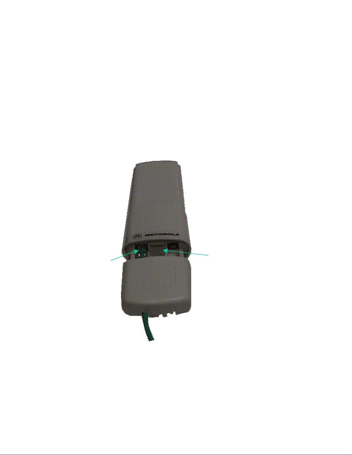
2. Getting to Know your Radio.
- The base cover snaps off the gain access to connectors and LED’s.
D R A F T – 9/10/2001
WHiSP SM
RJ45
Connector
Ethernet
Cable
Connection
LEDs
Base Cover
Page 4
D R A F T – 9/10/2001
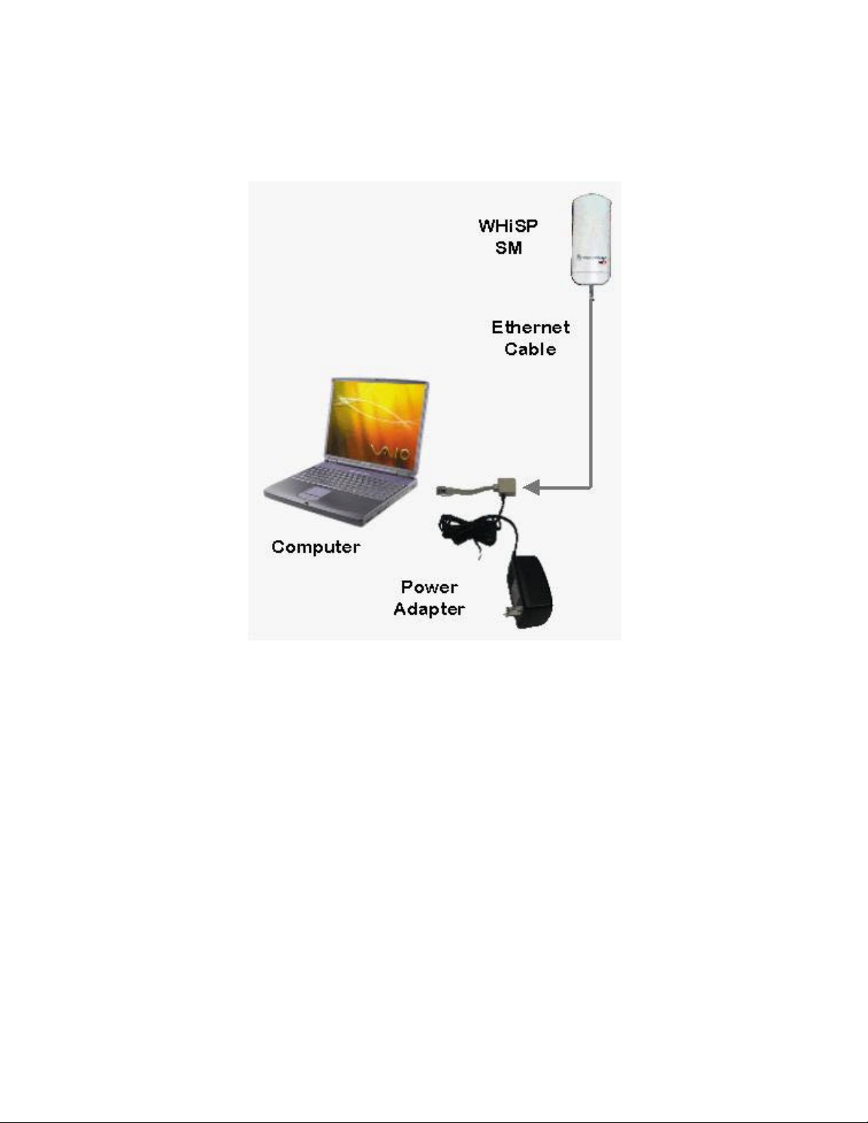
Installing WHiSP
Mount your WHiSP radio in a location where it is facing the transmitting tower
- Plug the power adapter’s Ethernet patch into your PC Ethernet port.
- Connect an Ethernet cable between the other side of the power adapter Ethernet patch
and the RJ45 socket on the WHiSP SM.
- See the section on “Aligning your WHiSP” in the trouble shooting section of this
manual to insure best performance.
- IMPORTANT NOTE: To comply with FCC RF exposure compliance requirements,
the following antenna installation and device operating configurations must be
satisfied. The antenna used for this transmitter must be installed to provide a
separation distance of at least 20cm from all persons and must not be co-located or
operating in conjunction with any other antenna or transmitter. Installers and end users must be provided with antenna installation instructions and transmitter
operating conditions for satisfying RF exposure compliance.
Page 5
D R A F T – 9/10/2001
Configuring your computer
Your PC will not require any special setup beyond proper installation of Ethernet drives
& drivers. Configuration of your computer’s TCP/IP parameters will be specified by
your ISP. However, you will need to temporarily configure your computer’s TCP/IP
parameters in order to configure your WHiSP radio.
Configuring your Windows 98 computer
These instructions are for Windows98 and
presume you have already installed your
Ethernet card or Network Interface Card (NIC),
and have installed TCP/IP protocols. If these
are not yet installed, they must be installed
before proceeding.
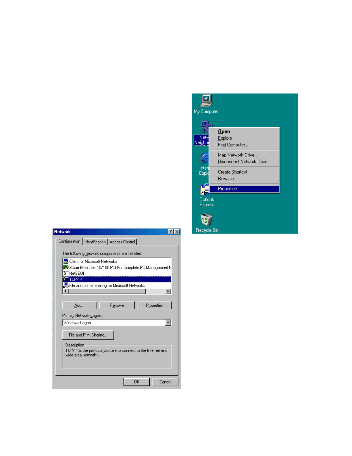
To temporarily reconfigure your TCP/IP
protocol to configure your WHiSP radio, first
begin by RIGHT clicking on the Network
Neighborhood icon on your desktop. A side
menu appears, and you must LEFT click on the
bottom item labeled “Properties”.
Presuming your Network Interface Card
(NIC) or Ethernet card is already
installed along with the TCP/IP protocol,
you will see both under the list of
network components installed.
Click the TCP/IP protocol item in the
component list to highlight it, and then
click on the “Properties” button.
This will bring up the TCP/IP Properties
screen shown next.
Page 6
D R A F T – 9/10/2001
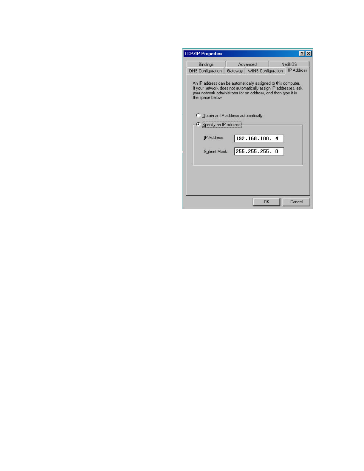
In order to configure your WHiSP radio,
you must temporarily assign a fixed IP
address to your computer.
Click the radial “Specify an IP address” so
that a dot appears. Then you may enter a
temporary IP address and subnet mask.
Enter the IP address 192.168.100.4, and
subnet mask 255.255.255.0.
You may then click OK, and OK again to
the Network Properties dialog. Your
computer will copy some Windows install
files, and may ask for the Windows CD if
Windows install files (called CAB files)
were not copied to your hard drive at
installation time.
Your computer will typically indicate that
it needs to reboot before the settings take
effect. You will need to reboot before
proceeding to configure your WHiSP radio.
After configuring and alignment of your WHiSP radio, follow the service provider
instructions for returning your TCP/IP properties to “Obtain an IP address
automatically” or other “specific IP address” assigned value as instructed. Expect your
system to reinstall files (or ask for the Windows CD if CAB files are not copied on your
hard drive) and request reboot each time TCP/IP parameters are changed. You may
return your TCP/IP parameters to the specific temporary IP address at any time to review
or reconfigure your WHiSP radio.
Page 7

D R A F T – 9/10/2001
Configuring your Windows 2000 computer
To temporarily reconfigure your TCP/IP protocol to
configure your WHiSP radio, first begin by RIGHT
clicking on the Network Neighborhood icon on your
desktop. A side menu appears, and you must LEFT
click on the bottom item labeled “Properties”.
When you click properties a new window
will come up, it will look something like
this. When this window comes up, RIGHT
click on the icon labeled Local Area
Connection. Once again LEFT click the
properties button that is on the very bottom
of the box.
Presuming your Network Interface Card
(NIC) or Ethernet card is already installed
along with the TCP/IP protocol, you will see
the card listed under the “Connect using”
field, and the Internet Protocol (TCP/IP)
under the list of components used by this
connection.
Click the TCP/IP protocol item in the
component list to highlight it, and then click
on the “Properties” button.
This will bring up the TCP/IP Properties
screen shown next.
Page 8

D R A F T – 9/10/2001
In order to configure your WHiSP
radio, you must temporarily assign a
fixed IP address to your computer.
Click the radial “Use the following
IP address” so that a dot appears.
Then you may enter a temporary IP
address and subnet mask. Enter the
IP address 192.168.100.4, and subnet
mask 255.255.255.0.
Once you have entered the IP
address and subnet mask, you may
click the OK button, since you are
using Windows 2000 you will not
need to restart your computer.
After configuring and alignment of your WHiSP radio, follow the service provider
instructions for returning your TCP/IP properties to “Obtain an IP address
automatically” or other “specific IP address” assigned value as instructed. Since you
are using Windows 2000 you will not need to restart your computer. You may return
your TCP/IP parameters to the specific temporary IP address at any time to review or
reconfigure your WHiSP radio.
Page 9

D R A F T – 9/10/2001
Configuring the WHiSP radio
Once your computer TCP/IP properties have temporarily been assigned a IP address
192.168.100.4, you may communicate with the WHiSP radio. Open your web browser
(such as Microsoft Internet Explorer) and enter the radio default address: 192.168.100.1.
If the WHiSP radio is powered and properly connected to your computer, you will see the
WHiSP radio homepage or status page open in your web browser. These web pages are
within the WHiSP radio, and no connect ion with the Internet is required. Various web
pages within the WHiSP radio can be selected from the choices on the left.
Home
This is the WHiSP Zone Home page. You may select any of the other pages within the
WHiSP radio, such as the Status, Configuration, Alignment, Event Log, AP Eval
Data, Link Test, or Packet Stats.
Page 10

D R A F T – 9/10/2001
Status
Device type should read Subscriber Modem – Multipoint Mode. Any
other label indicates an inappropriate preconfiguration of the
WHiSP radio
Software Version should be noted in the event you have technical difficulties and
need to contact technical support
FPGA Version should be noted in the event you have technical difficulties and
need to contact technical support
Device ESN is the Link Layer Ethernet Address assigned to your WHiSP
radio. Every WHiSP radio, Ethernet card, or Network
Interface Card (NIC) will have a unique number preconfigured
Uptime is the length of time your WHiSP radio has been operating
since power was last applied
System Time is the time set by the wireless service provider
Session Status Scanning/Registering/Registered/Aiming
This information is for use of technical support
Data Slots Up This information is for use of technical support
Data Slots Down This information is for use of technica l support
Air Delay This information is for use of technical support
RSSI This information is for use of technical support
Jitter This information is for use of technical support
Ethernet Interface 10/100 Base T, either half or full Duplex
This information is for use of technical support
Page 11

D R A F T – 9/10/2001
Configuration
Device type The second line should read Subscriber Modem – Multipoint
Mode. Any other label indicates an inappropriate
preconfiguration of the WHiSP radio
RF Frequency
Scan List
Lan1 IP is preconfigured to the address 192.168.100.1 for all subscriber
Lan1 Subnet Mask is preconfigured to the value 255.255.255.0 for all subscriber
Default Gateway is preconfigured to the address 192.168.100.0 for all subscriber
Provider ID is the time set by the wireless service provider
Update Flash overwrites configuration previously saved to the WHiSP radio.
Reboot Initiates a radio reboot.
Data Slots Down This information is for use of technical support
Clear Changes Re-displays current configuration of WHiSP configuration.
Check only RF Freq uencies as instructed by your Wireless
Internet Service Provider (ISP). Only check “None” should
you be instructed by your service provider’s technical support.
modems. Change this only at the instruction of your service
provider’s technical support.
modems. Change this only at the instruction of your service
provider’s technical support.
modems. Change this only at the instruction of your service
provider’s technical support. This may be password protected.
Changes will not take effect until the radio is power-cycled or
rebooted.
Page 12

D R A F T – 9/10/2001
Alignment
Normal Operating Display
Operating Mode This will read SM is in Operating Mode or SM is in
Alignment Mode as an indication of the currently selected
mode.
Enable Alignment
Mode ON
Disable Alignment
Mode OFF
LED Bar Graph Reflects the received signal strength from the service
Click this button to put the radio into Alignment Mode, or to
update the Alignment Mode bar graph (should it not
automatically refresh every second).
Click this button to return the radio back to normal operating
mode when alignment is satisfactory (aim the radio for
maximum number of LEDs on the bar graph)
provider’s access point. Proper alignment is when the bar
graph shows the maximum number of lit LEDs. While in this
mode, the LED bar graph can be observed on the radio itself,
such that it is unnecessary to have visibility of the computer
screen while orienting the WHiSP radio.
Page 13

D R A F T – 9/10/2001
Alignment
Alignment Mode Display
Select “Alignment” on the “WHiSP Zone” web page to obtain the alignment mode web
page. Click “Enable Alignment Mode ON” to display a bar graph of signal strength.
This will assist in adjusting the WHiSP radio for maximum alignment (maximum signal
strength). While the LED bar graph appears on your PC screen, the LEDs located inside
the WHiSP radio Base Cover will display the identical bar graph. Using either of these
LED bar graphs orient the WHiSP radio to maximize the signal strength. When done,
disable the alignment mode, by click ing on the “Disable Alignment Mode OFF” button
on the WHiSP zone web control.
Page 14

D R A F T – 9/10/2001
Event Log
Information on Event Log is for tech support personnel only.
The user should not clear this data unless instructed to do so by tech support personnel.
Page 15

D R A F T – 9/10/2001
AP Ev al Data
Information on AP Eval Data is for tech support personnel only.
Page 16

D R A F T – 9/10/2001
Link Test
Information on Link Test is for tech support personnel only.
Page 17

D R A F T – 9/10/2001
Packet Stats
Information on Packet Stats is for tech support personnel only.
Page 18

D R A F T – 9/10/2001
Specifications
Operating Frequency Range
U-NII Mid band 5.25 to 5.35 GHz
Access Method TDD/TDMA
Data Rate
Multipoint 10 Mbps
Modulation Type High Index BFSK/4FSK
(Optimized for interference
rejection)
Carrier to Interference (C/I) 3dB Ber 1*10-4
Receiver Sensitivity -84dBm 1*10-4
Error Floor Better than 10-9 BER, unfaded
Operating Range (All Weather)
Up to 2 miles with integrated antenna
Transmitter Power Meets FCC UNII ERP Limit
DC Power 24 VDC @ 0.3 Amp (active state)
Interface 10 Base-T, RJ45
Rate auto negotiated (802.3 compliant)
Protocols Used by WHiSP IPV4, UDP, TCP, ICMP, Telnet, HTTP, FTP, SNMP
Protocols Supported by WHiSP Switched Layer 2 Transport with support for all common Ethernet
protocols including IPV6, NetBIOS, DHCP, IPX, etc.
Software Upgrade Path Remotely downloaded into FLASH via RF link
Network Management HTML, TELNET, SNMP
Environmental
Wind 190 km/hr
Humidity Relative Humidity 95% at 35?C
Temperature -30? to +65? C
Physical
Dimensions 8.5”H x 4.0”W x 1.1”D (21.6 cm x 10.2 cm x 2.8 cm)
Weight Approx 1 lb, 0.5 kg
 Loading...