

Page 1

Gigabit Ethernet/82543
PMC Module
Owner’s Manual
214134 Revision AB
April 2005 Edition
Page 2

© Copyright 2005 Motorola Inc.
All rights reserved.
Printed in the United States of America.
Motorola and the stylized M logo are trademarks of Motorola, Inc., registered in the U.S.
Patent and Trademark Office.
Alaska and Marvell are trademarks of the Marvell Technology Group Ltd.
IEEE is a registered trademark of the Institute for Electrical and Electronics Engineers, Inc.
Intel is a registered trademark of Intel Corporation.
All other product or service names mentioned in this document are the property of their
respective owners.
Page 3

Page 4

Safety Summary
The following general safety precautions must be observed during all phases of operation, service, and repair of this
equipment. Failure to comply with these precautions or with specific warnings elsewhere in this manual could result
in personal injury or damage to the equipment.
The safety precautions listed below represent warnings of certain dangers of which Motorola is aware. You, as the
user of the product, should follow these warnings and all other safety precautions necessary for the safe operation of
the equipment in your operating environment.
Ground the Instrument.
To minimize shock hazard, the equipment chassis and enclosure must be connected to an electrical ground. If the
equipment is supplied with a three-conductor AC power cable, the power cable must be plugged into an approved
three-contact electrical outlet, with the grounding wire (green/yellow) reliably connected to an electrical ground
(safety ground) at the power outlet. The power jack and mating plug of the power cable meet International
Electrotechnical Commission (IEC) safety standards and local electrical regulatory codes.
Do Not Operate in an Explosive Atmosphere.
Do not operate the equipment in any explosive atmosphere such as in the presence of flammable gases or fumes.
Operation of any electrical equipment in such an environment could result in an explosion and cause injury or damage.
Keep Away From Live Circuits Inside the Equipment.
Operating personnel must not remove equipment covers. Only Factory Authorized Service Personnel or other
qualified service personnel may remove equipment covers for internal subassembly or component replacement or any
internal adjustment. Service personnel should not replace components with power cable connected. Under certain
conditions, dangerous voltages may exist even with the power cable removed. To avoid injuries, such personnel
should always disconnect power and discharge circuits before touching components.
Use Caution When Exposing or Handling a CRT.
Breakage of a Cathode-Ray Tube (CRT) causes a high-velocity scattering of glass fragments (implosion). To prevent
CRT implosion, do not handle the CRT and avoid rough handling or jarring of the equipment. Handling of a CRT
should be done only by qualified service personnel using approved safety mask and gloves.
Do Not Substitute Parts or Modify Equipment.
Do not install substitute parts or perform any unauthorized modification of the equipment. Contact your local
Motorola representative for service and repair to ensure that all safety features are maintained.
Observe Warnings in Manual.
Warnings, such as the example below, precede potentially dangerous procedures throughout this manual. Instructions
contained in the warnings must be followed. You should also employ all other safety precautions which you deem
necessary for the operation of the equipment in your operating environment.
Warning
To prevent serious injury or death from dangerous voltages, use extreme
caution when handling, testing, and adjusting this equipment and its
components.
Page 5

CE Notice (European Community)
This is a Class A product. In a domestic environment, this product may cause radio
interference, in which case the user may be required to take adequate measures.
Embedded Communications Computing products with the CE marking comply with the
EMC Directive (89/336/EEC). Compliance with this directive implies conformity to the
following European Norms:
EN55022 “Limits and Methods of Measurement of Radio Interference Characteristics
of Information Technology Equipment”; this product tested to Equipment Class A
EN55024 “Information technology equipment—Immunity characteristics—Limits and
methods of measurement”
Board products are tested in a representative system to show compliance with the above
mentioned requirements. A proper installation in a CE-marked system will maintain the
required EMC performance.
In accordance with European Community directives, a “Declaration of Conformity” has
been made and is available on request. Please contact your sales representative.
FCC Notice
This equipment has been tested and found to comply with the limits for a Class A digital
device, pursuant to Part 15 of the FCC rules.
Safety Notice for Information Technology Equipment
This equipment is to be used only with products that are certified by an internationally
recognized safety organization (for instance, UL or CSA).
Flammability
All Motorola PWBs (printed wiring boards) are manufactured with a flammability rating
of 94V-0 by UL-recognized manufacturers.
EMI Caution
This equipment generates, uses and can radiate electromagnetic energy. It
!
Caution
may cause or be susceptible to electromagnetic interference (EMI) if not
installed and used with adequate EMI protection.
Page 6

Notice
While reasonable efforts have been made to assure the accuracy of this document,
Motorola, Inc. assumes no liability resulting from any omissions in this document, or from
the use of the information obtained therein. Motorola reserves the right to revise this
document and to make changes from time to time in the content hereof without obligation
of Motorola to notify any person of such revision or changes.
Electronic versions of this material may be read online, downloaded for personal use, or
referenced in another document as a URL to the Motorola Embedded Communications
Computing website. The text itself may not be published commercially in print or
electronic form, edited, translated, or otherwise altered without the permission of
Motorola, Inc.
It is possible that this publication may contain reference to or information about Motorola
products (machines and programs), programming, or services that are not available in your
country. Such references or information must not be construed to mean that Motorola
intends to announce such Motorola products, programming, or services in your country.
Limited and Restricted Rights Legend
If the documentation contained herein is supplied, directly or indirectly, to the U.S.
Government, the following notice shall apply unless otherwise agreed to in writing by
Motorola, Inc.
Use, duplication, or disclosure by the Government is subject to restrictions as set forth in
subparagraph (b)(3) of the Rights in Technical Data clause at DFARS 252.227-7013
(Nov. 1995) and of the Rights in Noncommercial Computer Software and Documentation
clause at DFARS 252.227-7014 (Jun. 1995).
Motorola, Inc.
Embedded Communications Computing
2900 South Diablo Way
Tempe, Arizona 85282
Page 7

Contents
About this Manual
Audience ...................................................................................................................... xiii
Summary of Changes ................................................................................................... xiii
Overview of Contents .................................................................................................. xiv
Comments and Suggestions ......................................................................................... xiv
Conventions Used in This Manual .................................................................................xv
Abbreviations ............................................................................................................... xvi
CHAPTER 1 Preparation and Installation
Introduction................................................................................................................... 1-1
General Description ...................................................................................................... 1-1
Gigabit Ethernet Technology ........................................................................................ 1-2
High Performance.................................................................................................. 1-3
Standards-Based Technology................................................................................. 1-3
Cost-Effective Migration ....................................................................................... 1-3
Vendor Support ...................................................................................................... 1-4
System Enclosure.......................................................................................................... 1-4
Guidelines for Unpacking ............................................................................................. 1-5
Installation Preliminaries .............................................................................................. 1-5
Equipment Required ..................................................................................................... 1-6
Before You Install or Remove a Board ......................................................................... 1-6
Observe ESD Precautions...................................................................................... 1-6
Watch for Bent Pins or Other Damage .................................................................. 1-7
Use Caution When Installing or Removing Boards............................................... 1-8
Preserve EMI Compliance..................................................................................... 1-8
Understand Hot Swap ............................................................................................ 1-8
Recognize Different Injector/Ejector Lever Types ................................................ 1-9
Verify Slot Usage ................................................................................................. 1-10
Installation and Removal ............................................................................................ 1-11
Installation of Gigabit Ethernet/82543 PMC Module on a Host Board .............. 1-11
Installing a Board Module into the Chassis ......................................................... 1-13
Connecting the Ethernet Cable to the PMC Module ........................................... 1-15
Removal of Gigabit Ethernet/82543 PMC Module from a Host Board .............. 1-17
vii
Page 8

CHAPTER 2 Functional Description
Introduction ...................................................................................................................2-1
Product Features ............................................................................................................2-1
Functional Components.................................................................................................2-2
Intel 82543GC Ethernet LAN Controller...............................................................2-2
Marvell Alaska 88E1000 Gigabit Ethernet Transceiver ........................................2-4
Serial EEPROM .....................................................................................................2-4
Interrupt Request Line ...................................................................................................2-5
Device Drivers...............................................................................................................2-5
Ethernet Address............................................................................................................2-5
Regulatory Compliance .................................................................................................2-5
CHAPTER 3 Controls, Indicators and Connector Pin Assignments
Introduction ...................................................................................................................3-1
Bezel Connector and LEDs ...........................................................................................3-1
J1 and J2 PCI Bus Connectors.......................................................................................3-3
J3 PCI Bus Connector....................................................................................................3-7
RJ-45 Ethernet Connector .............................................................................................3-9
Cross-Over Cable Connector (10/100 Mb/s Only).....................................................3-10
Loopback Connector (10/100 Mb/s Only)...................................................................3-11
APPENDIX A Troubleshooting
Error List.....................................................................................................................A-1
APPENDIX B Specifications
Specifications.............................................................................................................. B-1
Safety Compliance ................................................................................................ B-1
Physical Requirements ..........................................................................................B-1
Power Requirements.............................................................................................. B-2
Environmental Requirements ................................................................................ B-3
EMC Compliance ....................................................................................................... B-5
APPENDIX C Related Documents
Embedded Communications Computing Documents................................................. C-1
Manufacturers’ Documents ........................................................................................ C-2
Related Specifications ................................................................................................ C-2
viii
Page 9

List of Figures
Figure 1-1. PMC/Gigabit Ethernet/82543 .................................................................... 1-2
Figure 1-2. Injector/Ejector Lever Types ................................................................... 1-10
Figure 1-3. Installing the Gigabit Ethernet/82543 PMC Module on Host Board ...... 1-12
Figure 1-4. General Host Board Installation .............................................................. 1-14
Figure 1-5. Connecting to the Network ..................................................................... 1-16
Figure 2-1. Functional Block Diagram ........................................................................ 2-2
Figure 3-1. Bezel Connector and LEDs ....................................................................... 3-2
Figure 3-2. RJ–45 Ethernet Connector Pin Layout ...................................................... 3-9
ix
Page 10

Page 11

List of Tab les
Table 2-1. Supported Mode Settings............................................................................. 2-3
Table 3-1. Bezel Connector and LEDs.......................................................................... 3-2
Table 3-2. J1 PCI Bus Connector Pin Assignments...................................................... 3-4
Table 3-3. J2 PCI Bus Connector Pin Assignments...................................................... 3-5
Table 3-4. J1 and J2 PCI Bus Connector Signal Definitions ........................................ 3-6
Table 3-5. J3 PCI Bus Connector Pin Assignment ....................................................... 3-8
Table 3-6. J3 PCI Bus Connector Signal Definitions.................................................... 3-9
Table 3-7. RJ–45 Ethernet Connector Pin Assignments ............................................. 3-10
Table 3-8. RJ-45 Ethernet Connector Signal Definitions ........................................... 3-10
Table 3-9. Cross-Over Cable Connections.................................................................. 3-10
Table 3-10. Loopback Connections ............................................................................ 3-11
Table 3-1. Troubleshooting an Installation .................................................................. A-2
Table 3-1. Physical Specifications ................................................................................B-1
Table 3-2. Power Requirements ....................................................................................B-3
Table 3-3. Environmental Requirements ......................................................................B-4
Table C-1. Embedded Communications Computing Documentation...........................C-1
Table C-2. Manufacturers’ Documents .........................................................................C-2
Table C-3. Related Specifications .................................................................................C-2
xi
Page 12

About this Manual
This manual describes and explains how to install the Gigabit Ethernet
82543 PCI mezzanine card (PMC). This network interface card (NIC) is
designed for the PCI bus and operates independently of a host processor.
Audience
This manual is intended for anyone who designs OEM systems, supplies
additional capability to existing compatible systems, or works in a lab
environment for experimental purposes. It is important to note that a basic
knowledge of computers and digital logic is assumed.
It is presumed that users have knowledge and working experience with:
❏ Basic concepts and uses of Ethernet networks
❏ Peripheral Component Interconnect (PCI) bus
❏ PCI Mezzanine Cards (PMCs)
Summary of Changes
This is the second release of the Gigabit Ethernet/82543 PMC Module
Installation and Use guide.
Date Description of Change
June 2001 Initial print.
April 2005 Modified Figure 1-3 on page 1-12.
Updated Table 3-6 on page 3-9.
Included UL details.
Modified Power Requirements on page B-2.
Added EMC Compliance on page B-5.
Editorial changes.
xiii
Page 13

Overview of Contents
This manual is divided into the following chapters and appendices:
Chapter 1, Preparation and Installation, provides a brief description of the
Gigabit Ethernet/82543 PMC Module. It also provides basic startup and
hardware preparation information. The remainder of the chapter describes
the installation procedure for the Gigabit Ethernet/82543 PMC Module.
Chapter 2, Functional Description, lists the features of the Gigabit
Ethernet 82543 PMC provided by the major onboard components. It also
provides a brief general description and a block diagram of Gigabit
Ethernet 82543 PMC. The remainder of the chapter is an overview of each
functional characteristic of the board along with a description of what
component or components provide each function.
Chapter 3, Controls, Indicators and Connector Pin Assignments, provides
a description of controls, indicators and onboard connectors of the Gigabit
Ethernet 82543 PMC as well as their pin assignments.
Appendix A, Troubleshooting, provides a hint list for detecting possible
errors. This chapter lists symptoms, probable causes, and recommended
corrective actions.
Appendix B, Specifications, provides general specifications of the Gigabit
Ethernet 82543 PMC including physical, power and environmental
specifications. This chapter also details the standard and EMC compliance
requirements of Gigabit Ethernet 82543 PMC.
Appendix C, Related Documents, provides a listing of related Motorola
product documentation, manufacturer’s documents and industry standard
specifications.
Comments and Suggestions
Motorola welcomes and appreciates your comments on its documentation.
We want to know what you think about our manuals and how we can make
them better. Mail comments to:
xiv
Page 14

Embedded Communications Computing
Reader Comments DW164
2900 S. Diablo Way
Tempe, Arizona 85282
You can also submit comments to the following e-mail address:
reader-comments@mcg.mot.com
In all your correspondence, please list your name, position and
company. Be sure to include the title and part number of the manual
and tell how you used it. Then tell us your feelings about its strengths
and weaknesses and any recommendations for improvements.
Conventions Used in This Manual
The following typographical conventions are used in this document:
bold
is used for user input that you type just as it appears; it is also used for
commands, options and arguments to commands and names of
programs, directories and files.
italic
is used for names of variables to which you assign values, for function
parameters and for structure names and fields. Italic is also used for
comments in screen displays and examples and to introduce new
terms.
courier
is used for system output (for example, screen displays, reports),
examples and system prompts.
<Enter>, <Return> or <CR>
represents the carriage return or Enter key.
Ctrl
xv
Page 15
!
Caution
Caution
represents the Control key. Execute control characters by pressing the
Ctrl key and the letter simultaneously, for example, Ctrl-d.
Note: Contains information that is not critical to the procedure, task, or
information you are describing. Notes are usually used to give the reader
a tip or additional information.
Identifies any risk of system failure, service interruption, or damage to
equipment and should explicitly state the nature of the risk and specify
how to reduce or avoid the risk.
Avoid touching areas of integrated circuitry; static discharge can damage
circuits.
Use ESD
Wrist Strap
Warning
Before you install or remove a board Motorola strongly recommends that
you use an antistatic wrist strap and a conductive foam pad.
Identifies any risk of personal injury or loss of life and should explicitly
state the nature of the risk and specify how to reduce or avoid the risk.
Abbreviations
The following abbreviations are used in this manual:
Abbreviation Meaning
BOM Bill of materials
CD Carrier detect
CSMA/CD Carrier Sense Multiple Access/Collision Detection
CSR Control/status register
xvi
Page 16

Abbreviation Meaning
DC Direct current
DSP Digital signal processor
EEPROM Electrically erasable programmable read-only memory
ESD Electrostatic discharge
FCC Federal Communication Commission
FIFO First-in/first-out
FTP File Transfer Protocol
GMII Gigabit Media Independent Interface
IEEE Institute of Electrical and Electronics Engineers
I/O Input/output
IRQ Interrupt request
LAN Local area network
LED Light emitting diode
LFM Linear feet per minute
MAC Media Access Control
MDI Media dependent interface
MII Media Independent Interface
MIB Management information base
MIS Management Information Service
NIC Network interface card
PCI Peripheral component interconnect
PMC PCI mezzanine card
RX Receive signal
SBC Single-board computer
SNMP Simple Network Management Protocol
TCP/IP Transmission Control Protocol/Internet Protocol
TX Transmit signal
UL Underwriters Laboratories Inc.
UTP Unshielded twisted-pair
xvii
Page 17

Page 18

1Preparation and Installation
Introduction
This chapter provides a brief description of the Gigabit Ethernet/82543
PMC Module and explains how to install the Gigabit Ethernet/82543 PMC
Module onto a host module, such as a single-board computer (SBC) or
carrier card, and how to connect the PMC to the network.
When you add PMCs to your system, verify that the combined power
!
Caution
(wattage) required for the PMCs does not exceed the system’s power
supply rating. Refer to your computer system documentation for this
information.
In this manual, the name Gigabit Ethernet/82543 PMC Module refers to all
models of the Gigabit Ethernet/82543 PMC Module series boards, unless
otherwise specified.
1
General Description
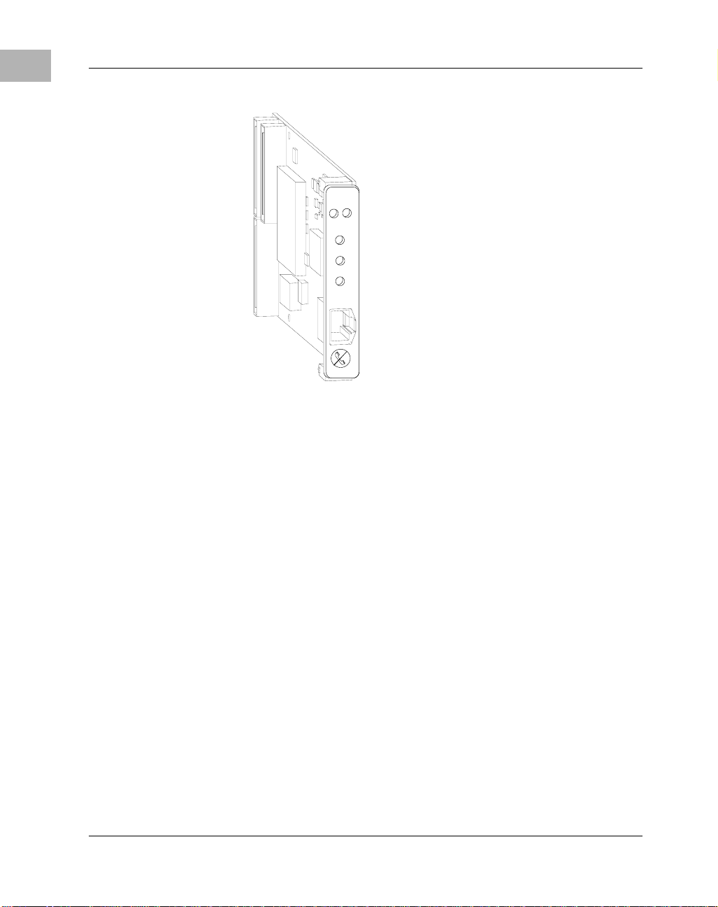
The Gigabit Ethernet 82543 PCI mezzanine card (PMC), shown in Figure
1-1 on page 1-2, is a network interface card (NIC) that provides a direct
interface to the local 32-bit or 64-bit PCI bus. Gigabit Ethernet technology
allows the PMC to use a single connector for 10 megabits per second (10Mb/s), 100 megabits per second (100-Mb/s), or 1000 megabits per second
(1000-Mb/s) Ethernet network connection (Institute for Electrical and
Electronics Engineers (IEEE) 802.3).
1-1
Page 19
1
Gigabit Ethernet Technology
ACT
FD
10
100
1000
ENET
Figure 1-1. PMC/Gigabit Ethernet/82543
Gigabit Ethernet Technology
Gigabit Ethernet (1000 Base-T) is a technology that can be integrated into
current 10 and 100 Base-T local area networks (LANs) and allow them to
upgrade easily to 1000 Mb/s. Gigabit Ethernet provides higher bandwidth
without a major change in infrastructure and is supported on major
platforms. It delivers an excellent business solution to increasing
requirements for bandwidth on a LAN.
Gigabit Ethernet technology offers the following advantages:
❏ High performance
❏ Standards-based technology
❏ Cost-effective migration
❏ Growing vendor support
1-2 Gigabit Ethernet/82543 PMC Installation and Use
Page 20

High Performance
In workgroup environments, Gigabit Ethernet can handle combined
demands of multiple LAN users and the peak traffic created by highperformance PCs and sophisticated applications that require significant
bandwidth.
Standards-Based Technology
The standard for Gigabit Ethernet technology is set by the IEEE 802.3
Committee, the same committee that developed the original Ethernet
standard and the Fast Ethernet standard. This technology is a simple
extension of 10/100 Base-T Ethernet. Gigabit Ethernet uses the Carrier
Sense Multiple Access/Collision Detection (CSMA/CD) protocol, defined
in the Ethernet Media Access Control (MAC) layer.
The 1000 Base-T MAC is a scaled up version of the MAC used in 10 and
100 Mb/s Ethernet. In other words, 1000Base-T is conventional Ethernet,
only faster. It is reliable, robust, and economical. Additionally, the
technologies can be offered with shared or switched Ethernet connections.
Shared environments provide a total of 10, 100, or 1000 Mb/s to all
stations attached to a hub. They are ideal for a medium-size workgroup
with occasional peak bandwidth demands. Shared Ethernet delivers the
bandwidth economically.
Gigabit Ethernet Technology
1
Cost-Effective Migration
The seamless compatibility between 10/100/1000 Base-T and prior
Ethernet implementations allows easy migration to high-speed
connections because of:
❏ LAN cabling
10/100/1000 Base-Tx Ethernet can run on the most common
unshielded twisted-pair (UTP) Ethernet wiring: 1000 BaseTx (1000
Mb/s) on Category 5e cabling, 100 BaseTx (100 Mb/s) on Category 5
cabling, and 10 BaseTx (10 Mb/s) on Category 3, 4, or 5 cabling.
❏ Administrative expertise
Gigabit Ethernet/82543 PMC Installation and Use 1-3
Page 21

1
System Enclosure
Managers can rely on familiar network analysis tools and procedures
in 10/100/1000 Base-T environments. Administrative information
translates easily from prior Ethernet implementations to 10/100/1000
Ethernet networks, which means minimal retraining of Management
Information Service (MIS) support staff. Administrators and system
integrators already know the technology, cabling, protocols, and
software.
❏ Management software
You can manage 10/100/1000 Ethernet LANs with existing Simple
Network Management Protocol (SNMP) management application
software and Ethernet management information bases (MIBs).
❏ Software support
Application and networking software functions unchanged on
10/100/1000 Base-T LANs.
❏ Flexible migration
Automatic speed selection, where controllers can run at 10, 100, or
1000 Mb/s on existing wire, ensures non disruptive transition to
Gigabit Ethernet. Similarly, 10/100/1000 Mb/s Ethernet switching
hubs enable smooth migration to Gigabit Ethernet in the wiring closet.
V e ndor Support
Gigabit Ethernet has the support of a growing number of vendors of
network controllers, network systems, and systems. Extensive multivendor support ensures the development of a wide range of interoperable
products.
System Enclosure
The type of system enclosure you use is determined by the configuration
and architecture of the host board (either SBC or carrier card). In some
cases, the host board and Gigabit Ethernet/82543 PMC Module assembly
requires only a single slot in the chassis. A customized chassis may
1-4 Gigabit Ethernet/82543 PMC Installation and Use
Page 22

accommodate a slightly wider board assembly into each slot. For more
information refer to the PMC specification, as referenced in Appendix C,
Related Documents.
Guidelines for Unpacking
If the shipping carton is damaged upon receipt, request that the carrier’s
agent be present during the unpacking and inspection of the equipment.
When unpacking, avoid touching areas of integrated circuitry; static
discharge can damage circuits.
Caution
Refer to the packing list and verify that all items are present. Save the
packing material for storing and reshipping of equipment.
Installation Preliminaries
Guidelines for Unpacking
1
Boards may be damaged if improperly installed or handled. Please read
and follow the guidelines in this section to protect your equipment.
This section applies to all hardware installations you may perform that
involve the Gigabit Ethernet/82543 PMC Module and host board. If the
host board is a hot-swap module, you can install it or remove it without
shutting down the operating system or removing system power. Replacing
a hot-swap module can be accomplished in under five minutes. For more
information about hot swap concepts and the PCI Industrial Computer
Manufacturer’s Group Hot Swap Specification (PICMG 2.1 R2.0), refer to
the sources listed in Appendix C, Related Documents.
Use ESD
Wrist Strap
Gigabit Ethernet/82543 PMC Installation and Use 1-5
Motorola strongly recommends that you use an antistatic wrist strap and a
conductive foam pad when installing or upgrading a system. Electronic
components, such as disk drives, computer boards and memory modules,
can be extremely sensitive to electrostatic discharge (ESD). After
removing the component from its protective wrapper or from the system,
Page 23

1
Equipment Required
place the component flat on a grounded, static-free surface (and, in the case
of a board, component side up). Do not slide the component over any
surface.
If an ESD station is not available, you can avoid damage resulting from
ESD by wearing an antistatic wrist strap (available at electronics stores)
that is attached to an active electrical ground. Note that a system chassis
may not be grounded if it is unplugged.
Equipment Required
To install the Gigabit Ethernet/82543 PMC Module, you need the
following equipment.
❏ System enclosure with power supply
❏ Host board
❏ Ethernet cable (Motorola recommends using Category 5 UTP
cabling)
Before You Install or Remove a Board
Boards may be damaged if improperly installed or handled. Please read
and follow the guidelines in this section to protect your equipment.
Refer to Appendix B, Specifications for details about the physical,
environmental and power requirements for the Gigabit Ethernet/82543
PMC Module.
Observe ESD Precautions
Use ESD
Wrist Strap
1-6 Gigabit Ethernet/82543 PMC Installation and Use
Motorola strongly recommends that you use an antistatic wrist strap and a
conductive foam pad when installing or upgrading a system. Electronic
components, such as disk drives, computer boards and memory modules,
can be extremely sensitive to electrostatic discharge (ESD). After
removing the component from its protective wrapper or from the system,
Page 24

Before You Install or Remove a Board
place the component flat on a grounded, static-free surface (and, in the case
of a board, component side up). Do not slide the component over any
surface.
If an ESD station is not available, you can avoid damage resulting from
ESD by wearing an antistatic wrist strap (available at electronics stores)
that is attached to an active electrical ground. Note that a system chassis
may not be grounded if it is unplugged.
Watch for Bent Pins or Other Damage
Damage to board/backplane or system components
!
Caution
Bent pins or loose components can cause damage to the board, the
backplane, or other system components.
Therefore, carefully inspect your board and the backplane for both pin and
component integrity before installation.
It is critical that two prerequisite steps be performed prior to installing your
board into the CompactPCI backplane to prevent possible backplane pin
damage.
1
❏ Visually inspect the board connectors to ensure they are not
damaged by previous insertions or accidental mishandling. If any
board connector damage is observed, do not install board into the
backplane. This may cause a bent pin on the connector, resulting in
an expensive repair.
❏ Visually inspect the backplane pins for any bent pins from previous
board installations in the slot where the board will be installed.
Embedded Communications Computing (ECC) and our suppliers take
significant steps to ensure there are no bent pins on the backplane or
connector damage to the boards prior to leaving our factory. Bent pins
caused by improper installation or by inserting boards with damaged
connectors could void the ECC warranty for the backplane or boards.
If a system contains one or more crushed pins, power off the system and
contact your local sales representative to schedule delivery of a
replacement chassis assembly.
Gigabit Ethernet/82543 PMC Installation and Use 1-7
Page 25

1
Before You Install or Remove a Board
Use Caution When Installing or Removing Boards
When first installing boards in an empty chassis, we recommend that you
start at the left of the card cage and work to the right when cards are
vertically aligned; in horizontally aligned cages, work from bottom to top.
When inserting or removing a board in a slot adjacent to other boards, use
extra caution to avoid damage to the pins and components located on the
primary or secondary sides of the boards.
Preserve EMI Compliance
Board/Component Damage
!
Caution
If the EMI barrier is open, devices may cause or be susceptible to excessive
interference.
Therefore, to preserve compliance with applicable standards and
regulations for electromagnetic interference (EMI), during operation all
front and rear openings on the chassis or board faceplates must be filled
with an appropriate card or covered with a filler panel.
Understand Hot Swap
Board/Component Damage
!
Caution
1-8 Gigabit Ethernet/82543 PMC Installation and Use
Inserting or removing non-hot swap cards or transition modules with
power applied may result in damage to module components.
Therefore, make sure that your board manufacturer identifies your module
as hot swap ready.
The PICMG 2.1 Hot Swap specification defines varying levels of hot
swap. A board that is compliant with the specification can be inserted and
removed safely with system power on without damage to onboard
circuitry. If a module is not hot swap compliant, you should remove power
to the slot or system before inserting or removing the module.
To facilitate hot swap, PICMG 2.1 specifies a blue LED on the faceplate.
This LED is under software control.
Page 26

!
Caution
Before You Install or Remove a Board
1
If your system is using software that provides full hot swap capabilities,
the software will illuminate the blue hot swap LED on the faceplate when
software has stopped and it is safe to remove the board.
If your system does not have hot-swap aware software running, behavior
of the blue LED may be indeterminate. In this case, you may need to
manually shut down applications or operating systems running on the
board prior to board removal, even if the blue LED is lit.
Corruption of Data or File System
Powering down or removing a board before the operating system or other
software running on the board has been properly shut down may cause
corruption of data or file systems.
Therefore, ensure that the board has been properly shut down. You should
ensure that the blue hot swap LED on the face plate of the host board is
illuminated.
Refer to the documents listed in Appendix C, Related Documents for more
information about hot swap and the PCI Industrial Computer
Manufacturers Group (PICMG) Hot Swap Specification.
Recognize Different Injector/Ejector Lever Types
The modules you install may have different ejector handles and latching
mechanisms. The following illustration shows the typical board ejector
handles used with ECC payload cards:
A) Elma Latching,
B) Rittal Type II,
C) Rittal Type IV.
All handles are compliant with the CompactPCI specification and are
designed to meet the IEEE1101.10 standards.
Gigabit Ethernet/82543 PMC Installation and Use 1-9
Page 27

1
Before You Install or Remove a Board
B CA
Figure 1-2. Injector/Ejector Lever Types
Each lever type has a latching mechanism to prevent the lever from being
opened accidentally. You must press the lever release before you can open
the lever. Never force the lever. If the lever does not open easily, you may
not have pressed firmly enough on the release. If the lever does not close
easily, the board may not be properly seated in the chassis.
To open a lever, press the release and move the lever outward away from
the faceplate.
To close a lever, move the lever inward toward the faceplate until the latch
engages.
Verify Slot Usage
Prevent possible damage to module components by verifying the proper
!
Caution
1-10 Gigabit Ethernet/82543 PMC Installation and Use
slot usage for your configuration.
Capability glyphs provide visual indication of backplane connector and
board capability. Capability glyphs are:
(Triangle) for System Slot
(Circle) for Peripheral Slots
Page 28

Installation and Removal
Installation and Removal
The following instructions tell how to install or replace the Gigabit
Ethernet/82543 PMC Module on a typical host board.
Installation of Gigabit Ethernet/82543 PMC Module on a Host Board
To install a Gigabit Ethernet/82543 PMC Module on a host board (either
SBC or carrier card), refer to the Figure 1-3 on page 1-12, read all cautions
and warnings and perform the following steps. This figure is for reference
only and may not represent the exact host board you are using.
Note: Since the Gigabit Ethernet/82543 PMC Module is not hot-swappable, always install the Gigabit Ethernet/82543 PMC Module when
power is turned off.
1
Damage of Carrier Card
!
Caution
!
Caution
!
Caution
Gigabit Ethernet/82543 PMC Installation and Use 1-11
The power supply circuits on carrier card may be overloaded if more than
one Gigabit Ethernet/82543 PMC Module modules are assembled. This
results in permanent damage to the carrier card.
Therefore, make sure that the carrier card’s 5V and 3.3V supply supports
the power requirements as described in Power Requirements on page B-2.
Damage of Circuits
Electrostatic discharge and incorrect board installation and removal can
damage circuits or shorten their life.
Therefore, before touching boards or electronic components, make sure
that you are working in an ESD-safe environment.
Module damage
Only mount permitted combinations of Gigabit Ethernet/82543 PMC
Module variants. Otherwise, damage to PMC module, carrier card and
Page 29

1
Installation and Removal
equipment attached to the rear transition board may occur.
Therefore, only install and use the PMC module together with the
Embedded Communications Computing’s carrier card.
1. Attach an ESD strap to your wrist. Attach the other end of the ESD
strap to the chassis as a ground. The ESD strap must be secured to
your wrist and to ground throughout the procedure.
PMC Connectors
Front Panel PMC cutout
Screws
Figure 1-3. Installing the Gigabit Ethernet/82543 PMC Module on Host Board
2. Perform an operating system shutdown. Turn the AC or DC power
off and remove the AC cord or DC power lines from the system.
Remove the chassis or system cover(s) as necessary to gain access
to the PMC module or host board.
3. Carefully remove the host board (either SBC or carrier card) from
its card slot and place it on a clean and adequately protected working
surface (preferably an ESD mat) with the backplane connectors
facing you.
4. Remove PMC slot filler panels from front panel of the carrier card.
1-12 Gigabit Ethernet/82543 PMC Installation and Use
Page 30

Installation and Removal
5. Remove the screws from the stand-offs on the Gigabit
Ethernet/82543 PMC Module.
6. Identify the PMC slot on the carrier card and insert the PMC's bezel
into the cutout on the front panel of the host module, as shown in
Figure 1-3 on page 1-12.
7. Align the PMC module over the PMC slot connectors: P11, P12 and
P13. Carefully press the PMC module into connectors. Ensure that
standoffs of the module are seated into the mounting holes of the
host board.
8. On the secondary side of the host board, fasten the four screws
through the holes in the host board and the spacers. Tighten the
screws.
The PMC module is now fully installed on the host board. Install the PMC
and host board assembly in its proper card slot by following the procedures
in Installing a Board Module into the Chassis.
For details regarding connecting the Ethernet cable to the RJ–45 connector
on the PMC Module front panel, refer to Connecting the Ethernet Cable to
the PMC Module on page 1-15.
1
Installing a Board Module into the Chassis
This section describes a recommended procedure for installing a board
module in a chassis.
Before you install your module, please read all cautions, warnings and
instructions presented in this section and the guidelines explained in
Before You Install or Remove a Board on page 1-6.
Use ESD
Handling modules and peripherals can result in static damage. Use a
grounded wrist strap, static-dissipating work surface and antistatic
Wrist Strap
Gigabit Ethernet/82543 PMC Installation and Use 1-13
containers when handling and storing components.
Page 31

1
4
Installation and Removal
Insert the board by gently holding the injector levers - do not exert
!
Caution
unnecessary pressure on the faceplate.
Hot swap compliant modules may be installed while the system is powered
on. If a module is not hot swap compliant, you should remove power to the
slot or system before installing the module. See Understand Hot Swap on
page 1-8 for more information.
Refer to the Figure 1-4 and perform these steps when installing modules.
Note that this illustration is for general reference only and may not
accurately depict the connectors and handles on the board you are
installing.
Stage 2
(Detail)
J5
J4
J3
J2
J1
Stage 1 Stage 3Stage 2
J5
J4
J3
J2
J1
4200 080
Figure 1-4. General Host Board Installation
1. Open the injector levers on your board (see Recognize Different
Injector/Ejector Lever Types on page 1-9).
2. Verify the proper slot for the module you are inserting (see Verify
Slot Usage on page 1-10). Align the edges of the module with the
card cage rail guides in the appropriate slot.
3. Using your thumbs, apply equal and steady pressure as necessary to
carefully slide the module into the card cage rail guides (Stage 1).
1-14 Gigabit Ethernet/82543 PMC Installation and Use
Page 32

Installation and Removal
Continue to gently push until the prealignment guide pegs engage
with the backplane connector (Stage 2) and the injector levers make
contact with the chassis rails. DO NOT FORCE THE BOARD
INTO THE BACKPLANE SLOT.
4. Use the injector levers to seat the module in the slot by closing the
levers until they latch into the locked position (Stage 3). If the levers
do not completely latch, remove the module from the chassis and
visually inspect the slot to ensure there are no bent pins.
Note: Install the PMC and host board assembly in its proper card slot.
Ensure it is seated properly in the backplane connectors. Do not damage
or bend connector pins.
5. When the module you are installing is completely latched, secure it
by tightening the captive screws at both ends of the faceplate.
6. Replace the chassis or system cover(s) and connect the system to the
AC or DC power source. Turn the equipment power on.
1
Connecting the Ethernet Cable to the PMC Module
Refer to Table 3-7 on page 3-10 for Ethernet connector pin assignments
and to Figure 1-5 on page 1-16 for a diagram showing the location of the
Ethernet connector on the PMC front panel.
1. Connect the Ethernet cable to the RJ–45 connector on the front
panel of the PMC (see Figure 1-5 on page 1-16).
For continued safe operation, connect the PMC to Ethernet wiring only.
!
Warning
Gigabit Ethernet/82543 PMC Installation and Use 1-15
Do not connect the PMC to telephone wiring.
Page 33

1
Installation and Removal
P
M
C
2
FD
ACT
10
Speed/Status LEDs
RJ-45 Connector
Ethernet Cable
Figure 1-5. Connecting to the Network
100
1000
P
M
C
1
ENET
2. Observe the appropriate green speed/status LED. The 10, 100, or
1000 Mb/s LED lights and stays lit when the PMC is connected to
the network properly.
3. Verify that the PMC is operational in the network by using the ping,
telnet/rlogin, and File Transfer Protocol (FTP) services of your
Transmission Control Protocol/Internet Protocol (TCP/IP)
environment.
– To establish a valid 1000-Mb/s connection, connect an
unshielded twisted pair (UTP) Category 5e cable either point-topoint or to a 1000 Base-Tx hub.
– To establish a valid 100-Mb/s connection, connect a UTP
Category 5 cable either point-to-point or to a 100 Base-Tx hub.
– To establish a valid 10-Mb/s connection, connect a UTP
Category 3, 4, or 5 cable either point-to-point or to a 10 Base-T
hub.
1-16 Gigabit Ethernet/82543 PMC Installation and Use
Page 34

Installation and Removal
Note: Auto-negotiation for speed and duplex is the default behavior for
most network devices that support it. However, to ensure that you know
how your network ports are operating, you should configure them explicitly for the correct speed and duplex for the connected device.
Removal of Gigabi t Ethernet/82543 PMC Module from a Host Board
To remove a Gigabit Ethernet/82543 PMC Module from a host board
(either SBC or carrier card), refer to Figure 1-3 on page 1-12 read all
cautions and warnings and perform the following steps.
Damage to module components
!
Caution
Inserting or removing modules with power applied may result in damage
to module components.
Therefore, ensure that you power down before inserting or removing the
Gigabit Ethernet/82543 PMC Module module.
1
Damage to Board or electronic components
!
Caution
Gigabit Ethernet/82543 PMC Installation and Use 1-17
Avoid touching areas of integrated circuitry; static discharge can damage
the circuits.
Therefore, before touching boards or electronic components, make sure
that you are working in an ESD-safe environment.
1. Attach an ESD strap to your wrist. Attach the other end of the ESD
strap to the chassis as a ground. The ESD strap must be secured to
your wrist and to ground throughout the procedure.
2. Perform an operating system shutdown. Turn the AC or DC power
off and remove the AC cord or DC power lines from the system.
Remove the chassis or system cover(s) as necessary to gain access
to the host board.
Page 35

1
Installation and Removal
3. Carefully remove the host module from its card slot and place it on
a clean and adequately protected working surface (preferably an
ESD mat) with the secondary side of the board facing up.
4. Remove the four screws from the holes in the host board that fasten
the Gigabit Ethernet/82543 PMC Module module to the host board.
5. Carefully turn the host board to the primary side and place on your
working surface. Gently separate the Gigabit Ethernet/82543 PMC
Module from the PMC connectors on the host board. Do not damage
or bend connector pins.
6. Tilt the board up slightly and remove it from the front panel slot.
1-18 Gigabit Ethernet/82543 PMC Installation and Use
Page 36

2Functional Description
Introduction
This chapter describes the Gigabit Ethernet/82543 PMC Module on a
feature and block diagram level. Figure 2-1 on page 2-2 shows a block
diagram of the overall board architecture.
The following sections contain detailed descriptions of several blocks of
circuitry.
Product Features
In addition to the features offered through Gigabit Ethernet technology, the
Gigabit Ethernet/82543 PMC Module features the following:
❏ PMC form factor
❏ 32- or 64-bit bus operations at speeds of 33 or 66 MHz
2
❏ Data rate of 125 Mb/s in half-duplex mode and 250 Mb/s in full-
duplex mode
❏ Standard RJ–45 connection
❏ Automatic speed selection
❏ 64 KB on-chip first-in/first-out (FIFO) data buffer for buffering
receive and transmit frames
❏ 1000 BaseTx (1000 Mb/s) on UTP Category 5e cabling, 100
BaseTx (100 Mb/s) on UTP Category 5 cabling, and 10 BaseTx (10
Mb/s) on UTP Category 3, 4, or 5 cabling
❏ Support for full-duplex mode, increasing the aggregate maximum
bandwidth up to 2000 Mb/s, 200 Mb/s, and 20 Mb/s
❏ Automatic media dependent interface (MDI) cross-over function for
all modes of operation, including 100 BaseTx and 10 BaseTx
2-1
Page 37

Functional Components
2
❏ Automatic polarity correction
❏ IEEE 802.3u auto-negotiation with next-page support for automatic
speed and duplex configuration
❏ Front panel light emitting diode (LED) status indicators
Functional Components
Figure 2-1 shows a functional block diagram of the Gigabit
Ethernet/82543 PMC Module. As the diagram shows, the key functional
components are the Intel 82543GC Ethernet LAN Controller, the Marvell
TM
Alaska
electrically erasable programmable read-only memory (EEPROM).
J1
J2
88E1000 Gigabit Ethernet Transceiver chip, and serial
Clock
PCI Bus
Clock
Intel
82543GC
Ethernet
Controller
Marvell
TM
Alaska
88E1000
Gigabit
Ethernet
Transceiver
10/100/1000Mb/s Magnetics,
Network Port,
and Switch
Cable (4 Pair)
RJ-45
J3
Serial
EEPROM
Figure 2-1. Functional Block Diagram
Intel 82543GC Ethernet LAN Controller
The Intel 82543GC Ethernet LAN Controller is a PCI bus controller that
supports IEEE 802.3 10 Mb/s, IEEE 802.3u 100 Mb/s, and IEEE 802.3z
and 802.3ab 1000 Mb/s data transfer rates. The controller is capable of
operating at bus speeds of 33 or 66 MHz, using bus widths of 32 or 64 bits.
2-2 Gigabit Ethernet/82543 PMC Installation and Use
Page 38

Functional Components
The controller interfaces to the PCI bus directly and supports the Media
Independent Interface (MII) for 10/100 Mb/s operation and the Gigabit
Media Independent Interface (GMII) for 10/100/1000 Mb/s operation.
Other features of the controller include:
❏ Integration of the 10 Mb/s, 100 Mb/s, and 1000 Mb/s physical layer
interfaces, which:
– Reduces the need for external support chips
– Provides full support for auto detection among network ports
– Improves performance
– Consumes less power
❏ Enhanced bus mastering capabilities
❏ High-speed data transfers over the PCI bus
❏ Processing of high-level commands and multiple operations, which
lowers CPU utilization by off-loading communication tasks from
the CPU
❏ A 64 KB on-chip FIFO data buffer that helps to prevent data
underruns and overruns while waiting for bus access
❏ Operation in full- or half-duplex mode
2
Table 2-1 lists speed and duplex mode combinations supported by the
controller with auto-negotiation enabled and disabled.
Table 2-1. Supported Mode Settings
Auto-Negotiation Enabled Auto-Negotiation Disabled
1000 Mb/s, full duplex 1000 Mb/s is NOT supported
100 Mb/s, full duplex 100 Mb/s, full duplex
100 Mb/s, half duplex 100 Mb/s, half duplex
10 Mb/s, full duplex 10 Mb/s, full duplex
10 Mb/s, half duplex 10 Mb/s, half duplex
Gigabit Ethernet/82543 PMC Installation and Use 2-3
Page 39

Functional Components
2
Note: Based on current errata to the Intel 82543GC Gigabit Ethernet
Controller Datasheet/Developer’s Manual (OR-2403), the 82543GC
Ethernet controller:
❏ Requires that auto-negotiation be enabled for 1000 Mb/s
operation
❏ Can operate at 1000 Mb/s only in full-duplex mode
Marvell Alaska 88E1000 Gigabit Ethernet Transceiver
The Marvell Alaska 88E100 Gigabit Ethernet Transceiver is the PMC’s
physical layer device. This integrated physical device supports 10BaseT,
100BaseT, and 1000BaseT applications with power dissipation lower than
2W. The device supports IEEE 802.3 compliant interfaces GMII and MII
and supports IEEE 802.3u and 802.3ab auto-negotiation with next-page
support. Together, the device’s digital signal processor (DSP) architecture,
mixed-signal processing, and digital design technology support features
such as digital adaptive equalization, echo and cross-talk cancellation, and
data recovery and error correction at a gigabit per second data rate.
For more information, see the product brief on the Marvell web site
(http://www.marvell.com).
Serial EEPROM
A 1 KB serial EEPROM stores the PMC’s Ethernet address and other
configuration information. The Intel 82543GC Ethernet LAN Controller
and its device driver use this information. The device driver for the
controller gains access to the EEPROM through the control/status register
(CSR). Routines are available for reading from and writing to the
EEPROM.
For more information on the contents of the EEPROM, see the
PMC/Gigabit Ethernet/82543 Driver Development Information. For more
information on the Intel 82543GC Ethernet LAN Controller's read and
write routines, see the Intel 82543GC Gigabit Ethernet Controller
Datasheet/Developer’s Manual (OR-2403).
2-4 Gigabit Ethernet/82543 PMC Installation and Use
Page 40

Interrupt Request Line
Interrupt Request Line
The interrupt request (IRQ) line for the Gigabit Ethernet/82543 PMC
Module is connected to PCI interrupt signal INTA.
Device Drivers
For information on supported device drivers for the Gigabit
Ethernet/82543 PMC Module, see the PMC/Gigabit Ethernet/82543
Supported Driver Information. For information on programming drivers
for the PMC, see the PMC/Gigabit Ethernet/82543 Driver Development
Information.
Ethernet Address
A unique Ethernet address is assigned to the PMC's Ethernet port at the
factory. For convenience, the address appears on a label on the back side
of the card.
Regulatory Compliance
2
The Gigabit Ethernet/82543 PMC Module complies with the following:
❏ FCC Class A
❏ CISPR-22 Class A
❏ CE Mark Class A
❏ UL/cUL Recognized Component
Gigabit Ethernet/82543 PMC Installation and Use 2-5
Page 41

Page 42

3Controls, Indicators and
Connector Pin Assignments
Introduction
This chapter provides details of controls, indicators as well as connector
pin assignments for all connectors on the Gigabit Ethernet/82543 PMC
Module. The following connectors on the Gigabit Ethernet/82543 PMC
Module, are described:
❏ J1 and J2 PCI Bus Connectors on page 3-3
❏ J3 PCI Bus Connector on page 3-7
❏ RJ-45 Ethernet Connector on page 3-9
❏ Cross-Over Cable Connector (10/100 Mb/s Only) on page 3-10
❏ Loopback Connector (10/100 Mb/s Only) on page 3-11
3
3
Bezel Connector and LEDs
Figure 3-1 on page 3-2 shows the connector and LEDs on the PMC's front
bezel. Table 3-1 on page 3-2 describes these components.
3-1
Page 43

Bezel Connector and LEDs
ACT
3
FD
1000
ENET
10
100
Activity Status LED
Duplex Status LED
10 Mb/s Link/Speed LED
100 Mb/s Link/Speed LED
1000 Mb/s Link/Speed LED
Figure 3-1. Bezel Connector and LEDs
Table 3-1. Bezel Connector and LEDs
Label Component Description
ACT Activity status
LED
FD Duplex status
LED
10 10 Mb/s A green LED. ON indicates 10 Mb/s mode
3-2 Gigabit Ethernet/82543 PMC Installation and Use
An amber LED. ON indicates receive
(RX) and transmit (TX) network activity
is occurring. OFF indicates no network
activity.
An green LED. ON indicates that full
duplex mode is enabled and OFF indicates
that half duplex mode is enabled.
is selected and a CD signal has been
detected.
Page 44

J1 and J2 PCI Bus Connectors
Table 3-1. Bezel Connector and LEDs (Continued)
Label Component Description
100 100 Mb/s A green LED. ON indicates 100 Mb/s
mode is selected and a CD signal has been
detected.
1000 1000 Mb/s A green LED. ON indicates 1000 Mb/s
mode is selected and a CD signal has been
detected.
ENET Connector A standard RJ–45 connector.
Note: Based on current errata to the Intel 82543GC Gigabit Ethernet
Controller Datasheet/Developer’s Manual (OR-2403), the 82543GC
Ethernet controller:
❏ Requires that auto-negotiation be enabled for 1000 Mb/s
operation
❏ Can operate at 1000 Mb/s only in full-duplex mode
3
J1 and J2 PCI Bus Connectors
Table 3-2 on page 3-4 and Table 3-3 on page 3-5 identify the 32-bit J1 and
J2 PCI bus connector pin assignments, respectively. Table 3-4 on page 3-6
defines the signals associated with the connector pins.
Note: An asterisk (*) in a signal name indicates that the signal is active
low.
Gigabit Ethernet/82543 PMC Installation and Use 3-3
Page 45

J1 and J2 PCI Bus Connectors
Table 3-2. J1 PCI Bus Connector Pin Assignments
Pin Signal Signal Pin
3
1 TCK -12V 2
3 GND INTA* 4
5INTB* INTC* 6
7BUSMODE1* +5V 8
9 INTD* NC 10
11 GND NC 12
13 CLK GND 14
15 GND GNT* 16
17 REQ* +5V 18
19 V(I/O) AD31 20
21AD28AD2722
23 AD25 GND 24
25 GND C/BE3* 26
27AD22AD2128
29 AD19 +5V 30
31 V(I/O) AD17 32
33 FRAME* GND 34
35 GND IRDY* 36
37 DEVSEL* +5V 38
39 GND LOCK* 40
41 SDONE* SBO* 42
43 PAR GND 44
45 V(I/O) AD15 46
47 AD12 AD11 48
49 AD09 +5V 50
51 GND C/BE0* 52
53AD06AD0554
55 AD04 GND 56
3-4 Gigabit Ethernet/82543 PMC Installation and Use
Page 46

J1 and J2 PCI Bus Connectors
Table 3-2. J1 PCI Bus Connector Pin Assignments (Continued)
Pin Signal Signal Pin
57 V(I/O) AD03 58
59AD02AD0160
61 AD00 +5V 62
63 GND REQ64* 64
3
Table 3-3. J2 PCI Bus Connector Pin Assignments
Pin Signal Signal Pin
1+12V TRST* 2
3TMS TDO 4
5 TDI GND 6
7 GND NC 8
9NC NC 10
11 BUSMODE2* +3.3V 12
13 RST* BUSMODE3* 14
15 +3.3V BUSMODE4* 16
17 NC GND 18
19 AD30 AD29 20
21 GND AD26 22
23 AD24 +3.3V 24
25 IDSEL AD23 26
27 +3.3V AD20 28
29 AD18 GND 30
31 AD16 C/BE2* 32
33 GND NC 34
35 TRDY* +3.3V 36
37 GND STOP* 38
39 PERR* GND 40
41 +3.3V SERR* 42
Gigabit Ethernet/82543 PMC Installation and Use 3-5
Page 47

J1 and J2 PCI Bus Connectors
Table 3-3. J2 PCI Bus Connector Pin Assignments (Continued)
Pin Signal Signal Pin
3
43 C/BE1* GND 44
45 AD14 AD13 46
47 GND AD10 48
49 AD08 +3.3V 50
51 AD07 NC 52
53 +3.3V NC 54
55 NC GND 56
57 NC NC 58
59 GND NC 60
61 ACK64* +3.3V 62
63 GND NC 64
Table 3-4. J1 and J2 PCI Bus Connector Signal Definitions
Signal Definition
+3.3V +3.3 V power supply
+5V +5 V power supply
–12V –12 V power supply
+12V +12 V power supply
ACK64* Acknowledge 64-bit transfers
AD<31:0> PCI address lines
BUSMODE<4:1>* Indicates the presence of a card in a given slot and sets the logical
protocol of the bus
C/BE<3:0>* PCI bus command and byte enable control and status
CLK PCI I/O clock signals
DEVSEL* PCI device select signals
FRAME* PCI data block transfer control signal
GND Ground
GNT* PCI bus mastering grant signal
IDSEL Logical slot ID signal
3-6 Gigabit Ethernet/82543 PMC Installation and Use
Page 48

J3 PCI Bus Connector
Table 3-4. J1 and J2 PCI Bus Connector Signal Definitions (Continued)
Signal Definition
INTA*, INTB*, INTC*,
INTD*
IRDY* PCI device initiator ready signal
LOCK* PCI data exchange bus control line signal
NC No connection
PAR Parity validation signal
PERR* PCI data and address parity error signal
REQ* PCI bus mastering request signal
REQ64* 64-bit transfer request signal
RST* PCI I/O reset signal
SBO* Snoop backoff
SDONE* Snoop done
SERR* PCI system error signal
STOP* PCI device data transfer stop signal
TCK Test clock
TDI JTAG, test data input
TDO JTAG, test data output
TMS TMS Test mode select
TRDY* Target ready
TRST* JTAG, test reset
V(I/O) Voltage I/O source
PCI device interrupt request signal
3
J3 PCI Bus Connector
Table 3-5 on page 3-8 identifies the 32-bit J3 PCI bus connector pin
assignments, respectively. Table 3-6 on page 3-9 defines the signals
associated with the connector pins.
Gigabit Ethernet/82543 PMC Installation and Use 3-7
Page 49

J3 PCI Bus Connector
Note: An asterisk (*) in a signal name indicates that the signal is active
low.
3
Table 3-5. J3 PCI Bus Connector Pin Assignment
Pin Signal Signal Pin
1 NC GND 2
3 GND C/BE7* 4
5 C/BE6* C/BE5* 6
7 C/BE4* GND 8
9V(I/O) PAR64 10
11 AD63 AD62 12
13 AD61 GND 14
15 GND AD60 16
17 AD59 AD58 18
19 AD57 GND 20
21 V(I/O) AD56 22
23 AD55 AD54 24
25 AD53 GND 26
27 GND AD52 28
29 AD51 AD50 30
31 AD49 GND 32
33 GND AD48 34
35 AD47 AD46 36
37 AD45 GND 38
39 V(I/O) AD44 40
41 AD43 AD42 42
43 AD41 GND 44
45 GND AD40 46
47 AD39 AD38 48
49 AD37 GND 50
3-8 Gigabit Ethernet/82543 PMC Installation and Use
Page 50

RJ-45 Ethernet Connector
Table 3-5. J3 PCI Bus Connector Pin Assignment (Continued)
Pin Signal Signal Pin
51 GND AD36 52
53 AD35 AD34 54
55 AD33 GND 56
57 V(I/O) AD32 58
59 NC NC 60
61 NC GND 62
63 GND NC 64
Table 3-6. J3 PCI Bus Connector Signal Definitions
Signal Definition
AD<63:32> PCI address lines
C/BE<7:4>* PCI bus command and byte enable control and status
GND Ground
PAR64 Parity validation signal
V(I/O) Voltage I/O source
3
RJ-45 Ethernet Connector
The RJ–45 Ethernet connector resides on the PMC’s bezel. Figure 3-2 on
page 3-9 shows the pin layout for the RJ–45 Ethernet connector (pin side
up). Table 3-7 on page 3-10 lists the connector pin assignments and Table
3-8 on page 3-10 lists the signal definitions.
1
56 7
234
Figure 3-2. RJ–45 Ethernet Connector Pin Layout
Gigabit Ethernet/82543 PMC Installation and Use 3-9
8
Page 51

Cross-Over Cable Connector (10/100 Mb/s Only)
Table 3-7. RJ–45 Ethernet Connector Pin Assignments
Pin Wire Color Signal
3
1 White/Green Data A+
2 Green/White Data A–
3 White/Orange Data B+
4 Blue/White Data C+
5 White/Blue Data C–
6 Orange/White Data B–
7 White/Brown Data D+
8 Brown/White Data D–
Table 3-8. RJ-45 Ethernet Connector Signal Definitions
Pin Signal
Data x+ Transmit/receive positive signal
Data x– Transmit/receive negative signal
Cross-Over Cable Connector (10/100 Mb/s
Only)
To connect two systems back-to-back, you must use a cross-over cable or
a network hub. Table 3-9 lists the connections for creating a cross-over
cable.
Table 3-9. Cross-Over Cable Connections
Connector 1 Pin Wire Color Signal Connector 2 Pin
1 White/Green Transmit+ 3
2 Green/White Transmit– 6
3 White/Orange Receive+ 1
4 Blue/White No connection 4
3-10 Gigabit Ethernet/82543 PMC Installation and Use
Page 52

Loopback Connector (10/100 Mb/s Only)
Table 3-9. Cross-Over Cable Connections (Continued)
Connector 1 Pin Wire Color Signal Connector 2 Pin
5 White/Blue No connection 5
6 Orange/White Receive– 2
7 White/Brown No connection 7
8 Brown/White No connection 8
Loopback Connector (10/100 Mb/s Only)
You can create a loopback connector with a plug by connecting the pins
listed in Table 3-10.
Table 3-10. Loopback Connections
Connect Pin... Signal To Pin... Signal
1 Transmit+ 3 Receive+
2 Transmit– 6 Receive–
3
Gigabit Ethernet/82543 PMC Installation and Use 3-11
Page 53

Page 54

Error List
This appendix provides a hint list for detecting erroneous system
configurations and any untoward or unusual behavior of the Gigabit
Ethernet/82543 PMC Module. It cannot replace a serious and sophisticated
pre- and post-sales support during application development.
If it is not possible to fix a problem using the Error List provided, contact
your local sales representative or FAE for further support.
Note: Table 3-1 on page A-2 assumes that the computer was operating
properly before you began the installation process and that the self-test
was successful.
ATroubleshooting
A
A-1
Page 55

A
Table 3-1. Troubleshooting an Installation
Problem Probable Cause Corrective Action
A speed/status LED flashes
green and does not change to
solid green when the cable is
connected.
The speed/status LED flashes
green and does not change to
solid green when the cable is
connected.
The 1000 Mb/s mode has been
selected, but the 1000 Mb/s
LED is not lit.
The cable connecting to the
PMC or the PMC connection
is faulty.
The PMC is faulty. For 10 Mb/s and 100 Mb/s
A carrier detect (CD) signal
could not be detected because
the network cable is loose,
disconnected, or connected to
a device that does not support
1000 Mb/s mode.
Verify the integrity of the
cable and cable connection. If
the cable is defective, replace
it. Verify that the cable has
been connected between
transmit to receive and receive
to transmit.
Note: Point-to-point system
connections require a crossover cable.
connections, connect a
loopback connector and
observe the results:
If the speed/status LED
changes to solid green (does
not flash), a problem exists
with the cable or the
concentrator.
If the speed/status LED
flashes green, replace the
PMC.
If no loopback connector is
available, test the
concentrator. If the
concentrator is functional,
replace the PMC.
Check that the network cable
is connected to the network
port, that the connection is
secure, and that the connected
device supports 1000 Mb/s
mode.
A-2 Gigabit Ethernet/82543 PMC Installation and Use
Page 56

Table 3-1. Troubleshooting an Installation (Continued)
Problem Probable Cause Corrective Action
The 100 Mb/s mode has been
selected, but the 100 Mb/s
LED is not lit.
The Ethernet speed does not
change automatically.
The PMC is preventing the
system from operating
correctly.
A CD signal could not be
detected because the network
cable is loose, disconnected,
or connected to a device that
does not support 100 Mb/s
mode.
Operating system settings are
not set correctly.
The network cable is loose. Secure the cable.
The PMC is faulty. Disconnect the network cable
A conflict exists with another
module.
Check that the network cable
is connected to the network
port, that the connection is
secure, and that the connected
device supports 100 Mb/s
mode.
Check whether the operating
system setting for the Ethernet
speed is 10, 100, or 1000 Mb/s
or is set for automatic speed
selection.
Configure network ports
explicitly for the correct speed
and duplex for the connected
device.
from the PMC. Turn off the
system, re-seat the PMC, and
turn the system on again. If
the problem persists, contact
your system administrator or
authorized Motorola
distributor.
Enable the PMC slot for bus
mastering.
Check that the slot is enabled.
A
Gigabit Ethernet/82543 PMC Installation and Use A-3
Page 57

Page 58

Specifications
This appendix provides general specifications including mechanical,
environmental and electrical for the Gigabit Ethernet/82543 PMC Module.
Safety Compliance
The Gigabit Ethernet/82543 PMC Module is a UL listed accessory.
This equipment is to be used only with products that are certified by an
internationally recognized safety organization (for instance, UL or CSA).
Physical Requirements
The Gigabit Ethernet/82543 PMC Module measures 149 mm by 74 mm
and is constructed using six-layer circuit board technology with four signal
layers and two power/ground layers. The PMC uses 32- and 64-bit PCI bus
connectors.
BSpecifications
B
The PMC must be installed on a host module (for example, an SBC or
carrier card) that has an available PMC slot with a removable front panel
slot cover. Table 3-1 gives the physical specifications of the Gigabit
Ethernet/82543 PMC Module.
Table 3-1. Physical Specifications
Characteristic Specification
Form factor Single PMC
PMC conformance IEEE P1386.1/Draft 2.0
PCI interface 32- or 64-bit, 33 or 66 MHz master and slave PCI
PCI controller Intel 82543GC
Protocols Ethernet 10 BaseTx, 100 BaseTx, 1000 BaseTx
B-1
Page 59

B
Table 3-1. Physical Specifications (Continued)
Receive/transmit FIFO 64 KB
Front panel I/O access RJ-45 connector
LED indicators Duplex, activity, and speed
Dimensions 74 mm x 149 mm
Power Requirements
Damage of PMC Module
!
Caution
!
Caution
The PMC Standard VITA 32 - 2003, Revision 1.0a, specifies a maximum
total power consumption of 5.15W per PMC module. The Gigabit
Ethernet/82543 PMC Module in its standard configuration may exceed
this value.
Therefore, it is necessary to synchronize the base board’s power supply
with the Gigabit Ethernet/82543 PMC Module power requirements. Due
to the high power dissipation, forced air-cooling is necessary.
Damage of power supply circuits
The power supply circuits on the carrier card may be overloaded if more
than one Gigabit Ethernet/82543 PMC Module module is assembled. This
results in permanent damage to the carrier card.
Therefore, make sure that the carrier card’s 3.3V and 5V supply supports
the power requirements as described in Table 3-2.
The current requirement for one PMC module is:
❏ 3.3V Rail : 1.56A typical
❏ 5V Rail : NA
This results in a typical total power consumption of 5.15W. However, the
carrier card should be able to provide maximum current requirements as
given below:
❏ 3.3V Rail : 1.73A maximum
B-2 Gigabit Ethe rnet /82543 PMC Installation and Use
Page 60

❏ 5V Rail : 0.4mAmp maximum
The power requirement of the Gigabit Ethernet/82543 PMC Module,
which is supplied by the carrier card, is detailed below in Table 3-2.
Table 3-2. Power Requirements
Requirement Value
Maximum power 5.71W
Maximum DC amps (+3.3 V) 1.73A
When you add PMCs to your system, verify that the combined power
!
Caution
(wattage) required for the PMCs does not exceed the system’s power
supply rating. Refer to your computer system documentation for this
information.
Environmental Requirements
The Gigabit Ethernet/82543 PMC Module features the industry-standard
PMC form factor. The PMC module must be placed on a carrier card.
The conditions listed below refer to the surroundings of the board within
the user environment.
B
Note: Operating temperatures refer to the temperature of the air circulating around the board and not to the component temperature.
Board Damage
!
Caution
Gigabit Ethernet/82543 PMC Installation and Use B-3
Do not operate the product outside the specified environmental limits.
High humidity, temperature and condensation may cause short circuits.
Therefore, ensure that the product is completely dry and there is no
moisture on any surface before applying power.
Page 61

B
!
Caution
Board Damage
Do not operate the product outside the specified environmental limits.
High humidity, temperature and condensation may cause short circuits.
Therefore, ensure that the product is completely dry and there is no
moisture on any surface before applying power.
Table 3-3 lists environmental requirements for the Gigabit Ethernet/82543
PMC Module.
Table 3-3. Environmental Requirements
Characteristic Specification
Temperature range
(at sea level)
Temperature
change
Air flow 200 linear feet per minute (LFM)
Relative humidity Operating : 5% to 95% @ 40°C (104°F) to 55°C (131°F)
Altitude Operating : -300 m to +3000 m
Shock Operating : 5 G / 11 ms halfsine — applied once in either
Vibration Operating : 10 to 15 Hz, 2 mm amplitude — 15 to
Free fall Operating : 100 mm / 3 axis
Radiated emissions FCC Class A, CISPR-22 Class A (dated 1998), CISPR-
Operating : 0°C to 55°C (32°F to 158°F)
Nonoperating : -40°C to 85°C (-40°F to 185°F)
Operating : ±0.5°C (33°F) per minute
Nonoperating : ±1.0°C (34°F) per minute
— noncondensing
Nonoperating : 5% to 95% @ 40°C (104°F) to 55°C
(131°F) — noncondensing
Nonoperating : -300 m to +13000 m
direction of three orthogonal axes
Nonoperating : 15 G / 11 ms halfsine — applied once in
either direction of three orthogonal axes
150 Hz, 2G
Nonoperating : 10 to 15 Hz, 5 mm amplitude — 15 to
150 Hz, 5G
Nonoperating : 1200 mm / all edges and corners
24 (dated 1998), CE Mark Class A, UL/cUL Recognized
Component
B-4 Gigabit Ethe rnet /82543 PMC Installation and Use
Page 62

EMC Compliance
The Gigabit Ethernet/82543 PMC Module is an add-on module meant to
be used in conjunction with standard SBC or carrier card. As such, it is the
responsibility of the OEM to meet the regulatory guidelines as determined
by their application.
The Gigabit Ethernet/82543 PMC Module has been tested in conjunction
with a standard Embedded Communications Computing baseboard and
chassis for CE certification and meets the requirements for EN55022 Class
A equipment. Compliance was achieved under the following conditions:
❏ Shielded cables on all external I/O ports
❏ Cable shields connected to earth ground via metal shell connectors
bonded to a conductive module front panel
❏ Conductive chassis rails connected to earth ground which provides
the path for connecting shields to earth ground
❏ Front panel screws properly tightened
For minimum RF emissions, it is essential that the conditions above be
implemented. Failure to do so could compromise the EMC compliance of
the equipment containing the module.
B
Gigabit Ethernet/82543 PMC Installation and Use B-5
Page 63

Page 64

CRelated Documents
Embedded Communications Computing Documents
The Motorola publications listed below are referenced in this manual. You
can obtain electronic copies of Embedded Communications Computing
publications by:
❏ Contacting your local Motorola sales office
❏ Visiting Embedded Communications Computing’s World Wide
Web literature site,
Table C-1. Embedded Communications Computing Documentation
Document Title Motorola Publication Number
PMC/Gigabit Ethernet/82543 Driver
Development Information
PMC/Gigabit Ethernet/82543 Supported
Driver Information
http://www.motorola.com/computer/literature
214135
214136
C
To obtain the most up-to-date product information in PDF or HTML
format, visit
http://www.motorola.com/computer/literature.
C-1
Page 65

C
Manufacturers’ Documents
Table C-2 lists the manufacturers’ data sheets and other useful manuals.
Please note that in many cases, the information is preliminary and the
revision levels of the documents are subject to change without notice.
Table C-2. Manufacturers’ Documents
Document Title and Source Publication Number
Intel 82543GC Gigabit Ethernet Controller
82543GC Gigabit Ethernet Controller Datasheet
OR-2710 82543GC Gigabit Ethernet Controller Developer’s
Manual
http://www.intel.com
Alaska™ 88E1000/88E1000S Integrated 10/100/1000 Gigabit
Ethernet Transceiver Datasheet
http://www.marvell.com/
Not Available
MV-S100153-00
Related Specifications
This table lists the product’s related specifications. The appropriate source
for the listed document is also provided. Please note that in many cases, the
information is preliminary and the revision levels of the documents are
subject to change without notice.
Table C-3. Related Specifications
Document Title and Source Publication Number
IEEE http://standards.ieee.org/catalog/
IEEE - Common Mezzanine Card Specification (CMC)
Institute of Electrical and Electronics Engineers, Inc.
IEEE - PCI Mezzanine Card Specification (PMC)
Institute of Electrical and Electronics Engineers, Inc.
C-2 Gigabit Ethernet/82543 PMC Installation and Use
P1386 Revision 2.0
P1386.1 Revision 2.0
Page 66

Table C-3. Related Specifications (Continued)
Document Title and Source Publication Number
IEEE Standard for Local Area Networks: Carrier Sense
Multiple Access with Collision Detection (CSMA/CD) Access
Method and Physical Layer Specifications
Institute of Electrical and Electronics Engineers, Inc.
PCI Industrial Manufacturers Group (PICMG) http://www.picmg.com/
Peripheral Component Interconnect (PCI) Local Bus
Specification,
Revision 2.0, 2.1, 2.2
Embedded PCI-X (ePCI-X) for Standard Form Factor PCI
Specification
Electronic Industries Alliance http://www.eia.org/
IEEE 802.3
PCI Local Bus Specification
PICMG 1.2 R1.0
C
Gigabit Ethernet/82543 PMC Installation and Use C-3
Page 67

Page 68

Index
Symbols
+5V signal .........................................3-4
Numerics
10 BaseTx .........................................2-1
10 BaseTx cabling
10 Mb/s
......................................1-1, 2-1
10 Mb/s connection
10 Mb/s LED
100 BaseTx
100 BaseTx cabling
100 Mb/s
....................................1-1, 2-1
100 Mb/s connection
100 Mb/s LED
1000 BaseTx
1000 BaseTx cabling
1000 Mb/s
..................................1-1, 2-1
1000 Mb/s connection
1000 Mb/s LED
-12V signal
12V signal
3.3V signal
.................................3-4, 3-6
..................................3-5, 3-6
.................................3-5, 3-6
32-bit PCI bus
32-bit PCI bus connectors
See PCI bus connectors
5V signal
...........................................3-6
64-bit PCI bus
82543GC Ethernet LAN Controller
B-1
............................1-3
.........................1-16
...........................1-16, 3-2
...............................2-1, A-3
..........................1-3
.......................1-16
.................1-16, 3-3, A-3
.............................2-1, A-2
........................1-3
.....................1-16
...............1-16, 3-3, A-2
.....................1-1, 2-1, 2-2
.....................1-1, 2-1, 2-2
.2-2,
A
ACK64 signal ................................... 3-6
Activity status (ACT) LED
AD signals
Address, Ethernet
Administration
........... 3-4, 3-5, 3-6, 3-8, 3-9
.......................2-4, 2-5
..................................1-3
Air flow requirements
............... 3-2
...................... B-4
Alaska 88E1000 Gigabit Ethernet Trans-
ceiver
............................2-2, 2-4
Altitude requirements
................................................ B-3
Amps
Analysis procedures
Analysis tools
....................................1-4
Automatic speed selection
Auto-negotiation
...................... B-4
..........................1-4
.1-4, 2-1, A-3
......................1-17, 2-4
B
Bandwidth ..................................1-2, 1-3
maximum
Before you install
Bezel
......................................... 3-1, B-2
Block diagram, functional
Board installation
Bus mastering
Bus speeds
Bus, interface to PCI
BUSMODE signals
....................................2-1
.............................. 1-5
................ 2-2
............................ 1-13
........................... 2-3, A-3
.................................2-1, 2-2
......................... 1-1
.............3-4, 3-5, 3-6
C
C/BE signals ................3-4, 3-6, 3-8, 3-9
Cable, Ethernet
......................1-15, 1-16
IN-1
Page 69

Index
N
D
E
X
checking connection of ......A-2, A-3
Cabling
...................................... 1-3, 2-1
cross-over cable
........................3-10
Carrier card
See Host module
Carrier detect (CD) signal
................A-2
Carrier Sense Multiple Access/Collision
Detection (CSMA/CD) protocol
1-3
Category 3 cabling
Category 4 cabling
Category 5 cable
Category 5 cabling
Category 5e cabling
Circuit board layers
CLK signal
................................ 3-4, 3-6
COM port, using
Command processing
Compliance, regulatory
Components, functional
Concentrator
Configuration information
........... 1-3, 1-16, 2-1
........... 1-3, 1-16, 2-1
..............................1-16
........... 1-3, 1-16, 2-1
..........................1-3
..........................B-1
.............................1-15
........................2-3
.....................2-5
....................2-2
.....................................A-2
................2-4
Connections
point-to-point
Connectors
cross-over cable connector
J1 PCI bus connector
pin assignments for .................3-4
signal definitions for ....... 3-6, 3-9
signals for ..............................3-4
J2 PCI bus connector
pin assignments for .................3-5
I
signal definitions for ....... 3-6, 3-9
signals for ..............................3-5
J3 PCI bus connector
pin assignments for .................3-8
signals for ..............................3-8
J4 PCI bus connector
loopback connector
....................1-16, A-2
........................................3-1
.......3-10
..................3-3
..................3-3
..................3-7
..................3-7
...........3-11, A-2
PCI bus connectors
RJ-45 connector
pin assignments for ...............3-10
pin layout for ..........................3-9
signal definitions for .............3-10
signals for ............................3-10
Control/status register (CSR)
Controller, Ethernet
Cross-over cable connector
Cross-talk cancellation
......3-3, 3-7, B-1
......... 1-15, 3-1, 3-9
............2-4
...........................2-2
.............3-10
......................2-4
CSMA/CD (Carrier Sense Multiple Ac-
cess/Collision Detection) protocol
.........................................1-3
CSR (control/status register)
.............2-4
D
Data buffer ........................................2-1
Data overruns
Data recovery
Data transfer rates
Data underruns
DC amps, maximum
Device drivers
DEVSEL signal
Digital adaptive equalizaiton
Digital design technology
Dimensions
Drivers
DSP architecture
Duplex modes
status LED (FD) for
Duplex status LED (FD)
....................................2-3
....................................2-4
.............. 2-1, 2-2, 2-3
..................................2-3
........................B-3
............................2-4, 2-5
..........................3-4, 3-6
............2-4
.................2-4
.............................. B-1, B-2
........................................2-4, 2-5
...............................2-4
............................2-1, 2-3
....................3-2
...................3-2
E
Echo cancellation ..............................2-4
EEPROM (electrically erasable pro-
grammable read-only memory)
2-2, .......................................2-4
IN-2 Gigabit Ethernet/82543 PMC Installation and Use
Page 70

Electrically erasable programmable
read-only memory (EEPROM)
2-2
, .......................................2-4
Emissions
ENET connector
Environmental requirements
Equipment required
equipment required
Error correction
ESD precautions
Ethernet address
Ethernet cable
......................................... B-4
...............................3-3
............ B-4
..........................1-6
...........................1-6
................................. 2-4
........................1-5, 1-6
.........................2-4, 2-5
.................................1-15
Ethernet connector
See RJ-45 connector
Ethernet LAN controller
Ethernet transceiver
Ethernet wiring
Ethernet, gigabit
........................1-3, 1-15
................................ 1-1
........... 2-2, B-1
...................2-2, 2-4
F
FD LED ............................................3-2
Features of Gigabit Ethernet/82543 PMC
Module
FIFO (first-in/first-out) data buffer
2-3, ...................................... B-2
File Transfer Protocol (FTP) service
1-16
First-in/first-out (FIFO) data buffer
2-3, ...................................... B-2
Form factor
FRAME signal
Free fall requirements
FTP (File Transfer Protocol) service
1-16
Full-duplex mode
Functional block diagram
Functional components
..........................1-1, 2-1
.. 2-1,
.....
.2-1,
............................... 2-1, B-1
...........................3-4, 3-6
...................... B-4
.....
.......................2-1, 2-3
................. 2-2
..................... 2-2
G
.
Gigabit Ethernet technology ...... 1-1, 1-2
Gigabit Ethernet transceiver
Gigabit Ethernet/82543 PMC
installation
removal
................................ 1-11
.....................................1-17
Gigabit Ethernet/82543 PMC Descrip-
tion
....................................... 1-1
Gigabit Media Independent Interface
(GMII)
..........................2-3, 2-4
GMII (Gigabit Media Independent Inter-
face)
..............................2-3, 2-4
GNT signal
.................................3-4, 3-6
H
Half-duplex mode ......................2-1, 2-3
High-speed connections
Host module
Hub connections
..................................1-3, 1-4, 3-10
Hubs
.............................. 1-1, B-1
............................. 1-16
.................... 1-3
Humidity requirements, relative
I
I/O access ......................................... B-2
IDSEL signal
IEEE 802.3 Committee
installation of PMC
Installation preliminaries
INTA signal
INTB signal
INTC signal
INTD signal
Integrators
Intel 82543GC Ethernet LAN Controller
Interrupt request (IRQ) line
Interrupt signal
IRDY signal
IRQ (interrupt request) line
.............................3-5, 3-6
.....................1-3
......................... 1-11
.................. 1-5
...............................3-4, 3-7
...............................3-4, 3-7
...............................3-4, 3-7
...............................3-4, 3-7
......................................... 1-4
...................................... 2-2
.................................. 2-5
...............................3-4, 3-7
.............. 2-5
......2-2, 2-4
...... B-4
, B-1
.............. 2-5
I
N
D
E
X
Gigabit Ethernet/82543 PMC Installation and Use IN-3
Page 71

Index
N
D
E
X
J
J1 PCI bus connector .........................3-3
pin assignments for
signals for
...................................3-4
J2 PCI bus connector
pin assignments for
signals for
...................................3-5
J3 PCI bus connector
pin assignments for
signals for
...................................3-8
J4 PCI bus connector
.....................3-4
.........................3-3
.....................3-5
.........................3-7
.....................3-8
.........................3-7
Management Information Service (MIS)
1-4
Marvell Alaska 88E1000 Gigabit Ether-
net Transceiver
..............2-2, 2-4
Media Access Control (MAC) layer
Media Independent Interface (MII)
2-4
MIBs (management information bases)
1-4
Migration
....................................1-3, 1-4
MII (Media Independent Interface)
.1-3
.2-3,
.
.2-3,
2-4
L
LAN controller ..........................2-2, B-1
LANs (local area networks)
cabling of
Layers, board
....................................1-3
....................................B-1
LEDs (light emitting diodes)
..............1-2
.....2-2, 3-1,
B-2
100 Mb/s
1000 Mb/s
speed
speed status
Light emitting diodes (LEDs)
....................................A-3
..................................A-2
..........................................A-2
...............................1-16
...2-2, 3-1,
B-2
100 Mb/s
1000 Mb/s
speed
speed status
Local area networks (LANs)
cabling of
LOCK signal
I
Loopback connector
....................................A-3
..................................A-2
..........................................A-2
...............................1-16
.............1-2
....................................1-3
............................. 3-4, 3-7
................3-11, A-2
M
MAC (Media Access Control) layer .1-3
Management information bases (MIBs)
1-4
MIS (Management Information Service)
1-4
Mixed-signal processing
................................................2-3
Modes
...................2-4
duplex status LED (FD) for
N
Network analysis ...............................1-4
Network connector
See RJ-45 connector
Network management software
Network speed
Next-page support
.................................A-3
.............................2-4
P
PAR signal ......................... 3-4, 3-7, 3-9
PAR64 signal
PCI bus
interface to
PCI bus connectors
PCI bus controller
PCI bus interface
PCI mezzanine card (PMC)
Peak traffic
Performance
PERR signal
Physical layer interface
....................................3-8
..............................................2-3
..................................1-1
.......................... B-1
............................ B-1
..............................B-1
..............1-1
........................................1-3
....................... 1-3, 2-1, 2-3
...............................3-5, 3-7
..............2-3, 2-4
........3-2
........1-4
IN-4 Gigabit Ethernet/82543 PMC Installation and Use
Page 72

Physical requirements ...................... B-1
Pin assignments
for cross-over cable connector
for J1 PCI bus connector
for J2 PCI bus connector
for J3 PCI bus connector
for loopback connector
for RJ-45 connector
Ping service
.....................................1-16
..................3-10
............. 3-11
.3-10
............ 3-4
............ 3-5
............ 3-8
PMC
description
PMC (PCI mezzanine card)
disconnecting
faulty
reseating
PMC conformance
PMC slot
enabling
Point-to-point connections
........................................ 1-1, B-3
Power
maximum
Power consumption
Power dissipation
Power supply rating
Procedures, network analysis
Protocols
.................................. 1-1
..............1-1
............................. A-3
.................................A-2, A-3
....................................A-3
........................... B-1
.......................................... B-1
..................................... A-3
......1-16, A-2
................................... B-3
..........................2-3
..............................2-4
.................. 1-1, B-3
............ 1-4
.......................................... B-1
R
Radiated emissions .......................... B-4
Receive frames, buffering
Receive signal
........................3-10, 3-11
Regulatory compliance
Relative humidity requirements
removal of PMC
REQ signal
REQ64 signal
.............................1-17
.................................3-4, 3-7
.............................3-5, 3-7
Requirements
air flow
altitude
...................................... B-4
....................................... B-4
................. 2-1
............. 2-5, B-4
....... B-4
environmental
free fall
physical
......................................... B-4
shock
temperature change
temperature range
vibration
RJ-45 connector
pin assignments for
pin layout for
signal definitions for
signals for
rlogin service
RST signal
.................................3-5, 3-7
............................ B-4
...................................... B-4
..................................... B-1
................... B-4
...................... B-4
.................................... B-4
.1-15, 2-1, 3-1, 3-3, 3-9
.................. 3-10
.............................. 3-9
................ 3-10
................................. 3-10
..................................1-16
S
SBC (single-board computer)
See Host module
SBO signal
SDONE signal
SERR signal
Shared Ethernet connnections
Shock requirements
Signal definitions
for PCI bus connectors
for RJ-45 connector
Signals
for cross-over cable connector
for J1 PCI bus connector
for J2 PCI bus connector
for J3 PCI bus connector
for loopback connector
for RJ-45 connector
interrupt
Simple Network Management Protocol
Single-board computer (SBC)
See Host module
Size
.................................................. B-1
.................................3-4, 3-7
...........................3-4, 3-7
...............................3-5, 3-7
........... 1-3
......................... B-4
........ 3-6, 3-9
.................. 3-10
............ 3-4
............ 3-5
............ 3-8
............. 3-11
.................. 3-10
...................................... 2-5
(SNMP)
................................ 1-4
.3-10
I
N
D
E
X
Gigabit Ethernet/82543 PMC Installation and Use IN-5
Page 73

Index
Slot cover .........................................B-1
Slot, PMC
.........................................B-1
enabling
.....................................A-3
SNMP (Simple Network Management
Protocol)
Software support
Software, network management
Speed
................................. 1-1, 2-3, A-3
Speed selection
Speed status LEDs
Speeds
...............................................2-1
...............................1-4
...............................1-4
........1-4
.......................... 1-4, 2-1
..................1-16, A-2
SROM
See EEPROM (electrically erasable
programmable read-only
memory)
Standards
Stations
STOP signal
Support, software
Switch hub
Switch hub connections
Switched Ethernet connections
Switching hubs
System integrators
...........................................1-3
..............................................1-3
.............................. 3-5, 3-7
..............................1-4
.......................................3-10
..................1-16
.........1-3
.......................... 1-3, 1-4
.............................1-4
Transmit frames, buffering
Transmit signal
TRDY signal
TRST signal
.......................3-10, 3-11
..............................3-5, 3-7
...............................3-5, 3-7
...............2-1
U
Unpacking the module ......................1-5
Unshielded twisted pair (UTP) cable
.....
1-16
Upgrading LANs
UTP (unshielded twisted pair) cable
...............................1-2
1-3,
............................................1-16
V
V(I/O) signal ............... 3-4, 3-7, 3-8, 3-9
Vibration requirements
....................B-4
W
Wattage .....................................1-1, B-3
Wiring
......................................1-3, 1-15
N
D
E
X
T
TCK signal ................................ 3-4, 3-7
TCP/IP (Transmission Control Proto-
col/Internet Protocol)
TDI signal
TDO signal
Telephone wiring
I
Telnet service
Temperature change requirements
................................. 3-5, 3-7
................................ 3-5, 3-7
............................1-15
..................................1-16
Temperature range requirements
TMS signal
................................ 3-5, 3-7
Tools, network analysis
Transmission Control Protocol/Internet
Protocol (TCP/IP)
IN-6 Gigabit Ethernet/82543 PMC Installation and Use
.........1-16
... B-4
..... B-4
.....................1-4
..............1-16
 Loading...