

Page 1
PHOTO
FACT*
Folder
MODELS
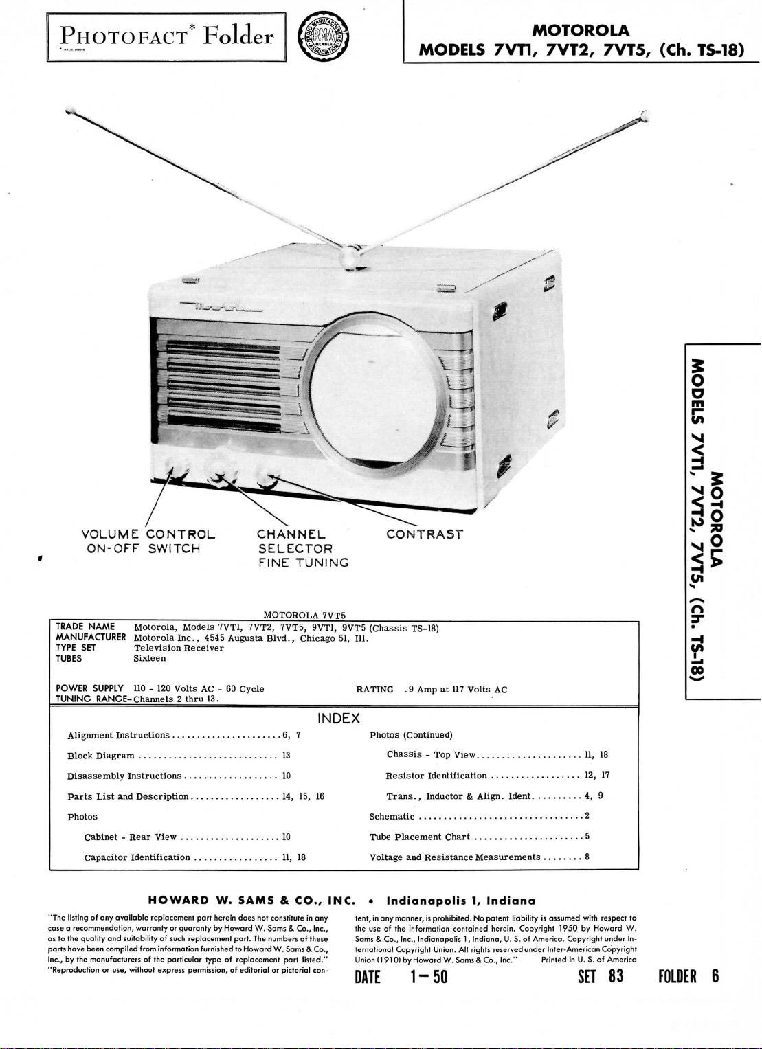
MOTOROLA
7VT1, 7VT2, 7VT5, (Ch.
TS-18)
o
o
m
VOLUME
CONTROL
ON-OFF SWITCH
TRADE
NAME
MANUFACTURER
TYPE
TUBES
POWER
TUNING
Alignment
Block Diagram
Motorola,
SET
Sixteen
Motorola
Television
SUPPLY
110 - 120
RANGE-
Channels 2 thru
Instructions
13
Disassembly Instructions
Parts
List
and
Description
Photos
Cabinet - Rear View
Capacitor Identification
HOWARD
"The listing
of any
available
case a recommendation, warranty
as
to the
quality
parts
Inc.,
by the
"Reproduction
and
have been compiled
manufacturers
or
replacement part herein does
suitability
from
of the
use, without
express
CHANNEL
SELECTOR
FINE
Models
Inc.,
Receiver
Volts
7VT1, 7VT2, 7VT5, 9VT1, 9VT5
4545
AC - 60
13.
Augusta
Cycle
MOTOROLA 7VT5
Blvd.,
6, 7
10
14, 15, 16
10
11, 18
W.
SAMS & CO., INC. • Indianapolis
not
or
guaranty
by
permission,
Howard
of
of
such replacement
information furnished
particular type
W.
part.
The
to
Howard
replacement
of
editorial
consfitute
Sams & Co.,
numbers
or
TUNING
Chicago
of
W.
Sams & Co.,
part
listed."
pictorial
INDEX
in any
Inc.,
these
con-
CONTRAST
(Chassis
51,
111.
RATING
Photos
Chassis
Resistor
Trans.,
Schematic
Tube Placement Chart
Voltage
tent,
in any
the
use of the
Sams & Co., Inc.,
ternational
Union
(1910)
DATE
1-50
TS-18)
. 9
Amp
at 117
Volts
AC
(Continued)
- Top
View
Identification
Inductor & Align.
and
Resistance Measurements
manner,
is
prohibited.
information contained herein. Copyright
Indianapolis
Copyright Union.
by
Howard
1,
All
W.Sams & Co.,
Ident.
1,
Indiana
No
patent
liability
Indiana,
U. S. of
rights reserved under Inter-American Copyright
Inc."
.
11, 18
12, 17
.
..
4, 9
.2
.5
.
is
assumed
with
1950
by
America. Copyright under
Printed
Howard
in U. S. of
SET
respect
to
W.
In-
America
83
FOLDER
Ul
S
/->
n
•
^
oo
6
Page 2
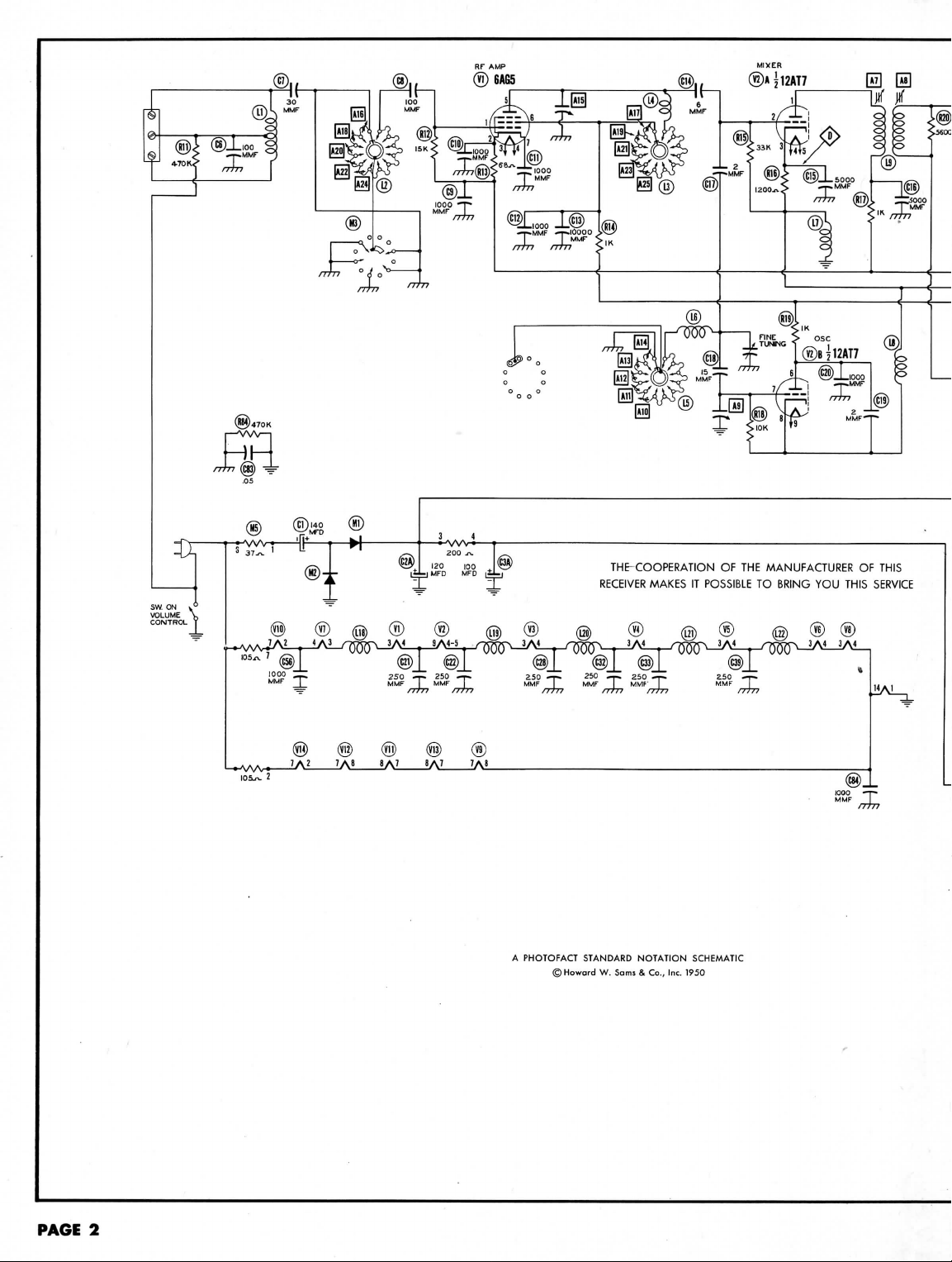
MIXER
©AJ12AT7
PAGE
2
A
PHOTOFACT STANDARD
©Howard
W.
NOTATION
Sams & Co., Inc. 1950
SCHEMATIC
1000
MMF
-r*
|
/7//Y
Page 3
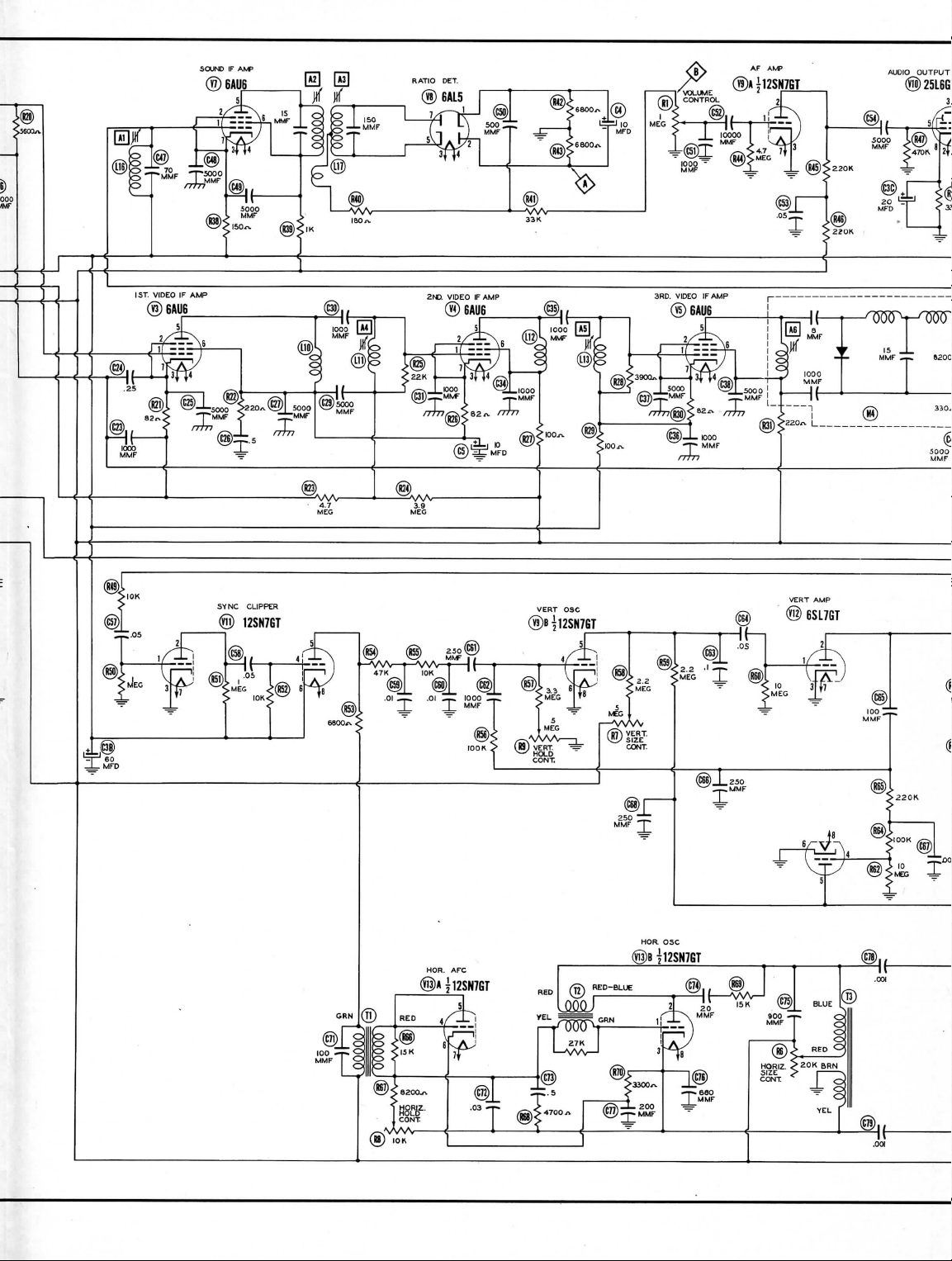
SOUND
IF AMP
AUDIO
OUTPUT
®
25L6G'
3]
Page 4
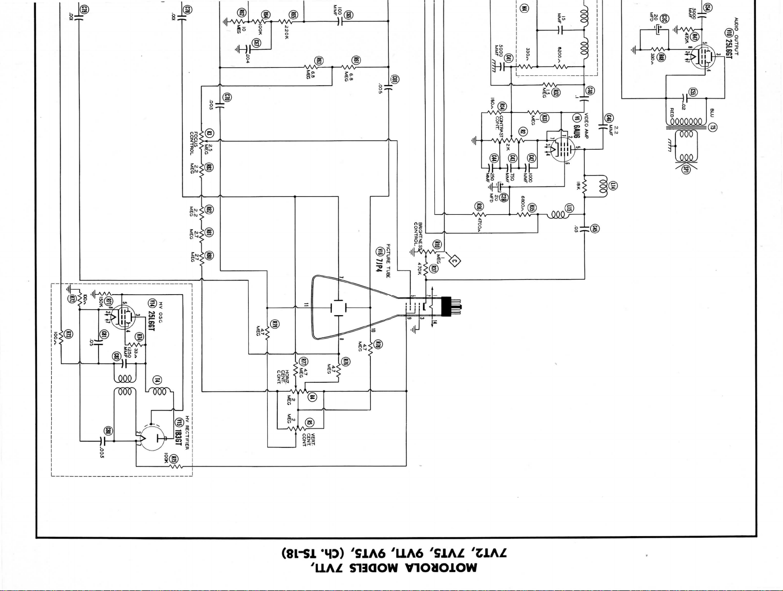
MOTOROLA
7VT2, 7VT5,
MODELS
9VT1,
7VH,
9VT5, (Ch.
TS-18)
Page 5
MOTOROLA
7VT2,
7VT5,
MODELS
9VT1,
7VT1,
9VT5, (Ch.
TS-18)
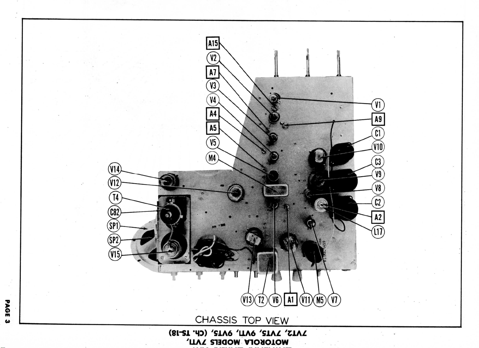
M3IA
dOl
SISSVHD
Page 6
PAGE
4
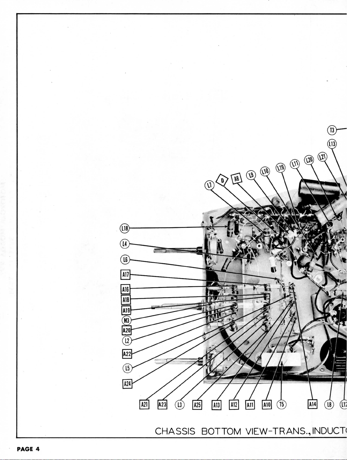
CHASSIS
BOTTOM
VIEW-TRANS.,
INDUCT(
Page 7
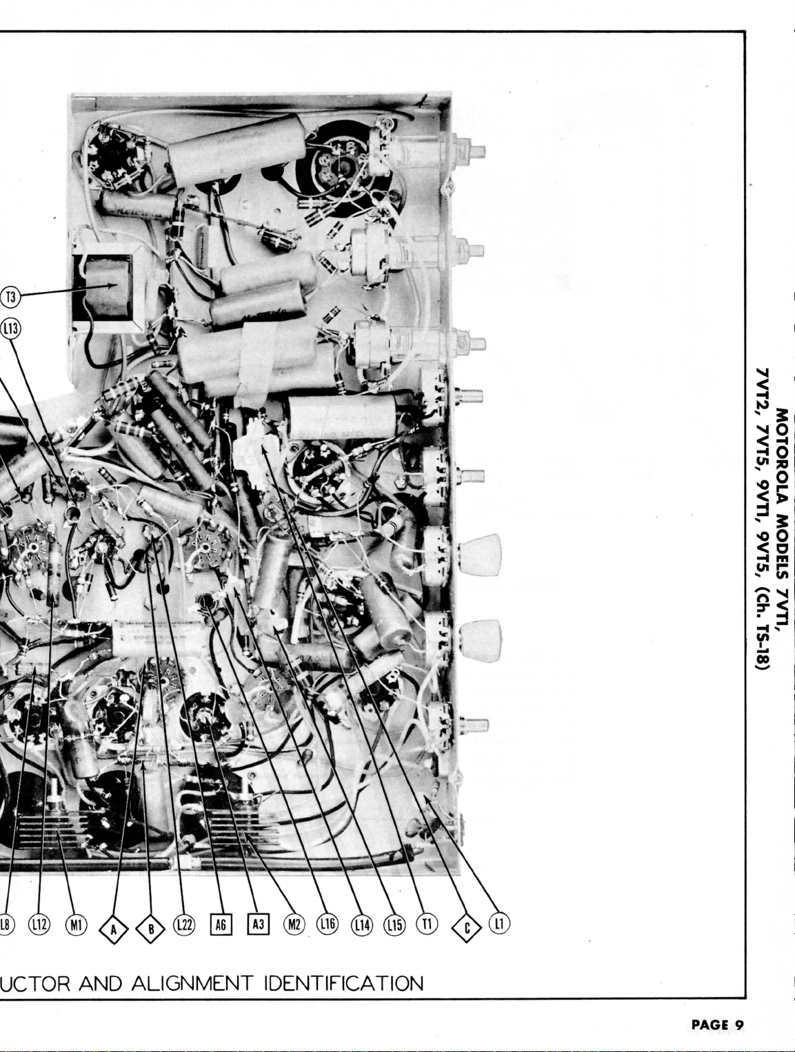
UCTOR
AND
ALIGNMENT
IDENTIFICATION
PAGE
9
Page 8

TOP
VIEW
VI3
\O
SYNC.
CUPPER
L
17
8
\ V9
\6AU6/
3RD
VIDEO
2ND
VIDEO
\6AU6/
IE
1ST
25L6OT
<z>
ID1O
OUTPUT
IF
CONVERTER
\6AU6y
\l2AT7y
VIDEO
IF RE
\6AG5y
AMP.
BOTTOM
2ND
VIDEO
IF
\I2AT7/
\6AU6/-
\^AU6/
RF
AMR
1ST
VIDEO
\6AU6
IF 3RD
VIDEO
IFI
TUBE PLACEMENT CHART
VIEW
VII
\C
I2SN7GT
/CLIPPER
T2
I
PAGE
5
Page 9

If
complete receiver
If
the
picture
Use
an
isolation transformer
Connect a 10KO
DUMMY
ANTENNA
High
.01MFD
of
6AU6
toB-.
.01MFD
Use
frequency
DUMMY
ANTENNA
High
.
01MFD
of
to
,
01MFD
Connect
the
Connect
Unsolder
If a wide
Set
DUMMY
ANTENNA
.01MFD
.01MFD
DUMMY
ANTENNA
.01MFD
Resolder
Set the
Connect
DUMMY
ANTENNA
Direct
Direct
Direct
synchronized
the
negative
une
band
contrast control
High
.
01MFD
of
toB-.
.01MFD
High
tube
converter
Low
the
cathode
fine
tuning
the
synchronized
High
terminal.
"G"
tube
is
isolating
SIGNAL
GENERATOR
COUPLING
side
(V6).
"
modulated
SWEEP
GENERATOR
COUPLING
side
6AU6
(V6).
B-.
end of the
scope
SWEEP
GENERATOR
COUPLING
side
6AU6
(V3).
"
"
SWEEP
GENERATOR
COUPLING
side
shield
side
control
SWEEP
GENERATOR
COUPLING
side
terminal.
alignment
removed,
resistor
to pin 1
Low
signal
to pin 1
Low
"
sweep voltage
lead
of a 3
oscillator
is
used,
to
minimum.
to pin 1
Low
to
ungrounded
floating
tube
(V2).
to
B~.
choke
(L7).
to
sweep voltage
.
to
upper
Low
side
ALIGNMENT
Is
to he
performed,
it
will
be
protect
with
side
in
series
GENERATOR
FREQUENCY
SOUND
4.
(450KC
necessary
the
test
equipment.
SOUND
IF
with
the
SIGNAL
4.
SMC
1
(Unmod. ) i
"
If
ALIGNMENT
60 ~ modulation
SWEEP
GENERATOR
FREQUENCY
SMC
Sweep)
to
(Grid)
side
(Grid)
It
can
most
to
short pins
ALIGNMENT
common
CHANNEL
Iny
channel
mused
1
ocally
"
USING
and
450KC
MARKER
GENERATOR
FREQUENCY
4.
SMC
INSTRUCTIONS
conveniently
1 and 14 of the
USING
AM
of the
VTVM
CONNECT
VTVM
DC
Probe
Common
to B-.
DC
Probe
Common
to B-.
FM
SIGNAL
sweep.
Use 120 ~ sawtooth
CHANNEL
Any
channel
unused
locally
SIGNAL GENERATOR
to
to
lead
'
F
ALIGNMENT
the
signal generator
lOKft
(L7),
to
capacitor across
MARKER
GENERATOR
FREQUENCY
22.
9MC
26.
SMC
"
.
"
L
t
IF
TRANSF
MARKER
GENERATOR
FREQUENCY
23.
IMC
26.
IMC
of
its
range.
signal generator
MARKER
GENERATOR
FREQUENCY
193.25MC
197.
75MC
175.
25MC
179.75MC
181.
25MC
185.
75MC
187.
25MC
191.
75MC
199.
25MC
203.
75MC
205.
25MC
209. 7 SMC
211.
25 MC
215.
75MC
83.25MC
87.75MC
77.25MC
81.
75MC
67.25MC
71.
75MC
61.
25MC
65.75MC
55.
25MC
59.75MC
VIDEO
to the
disable
to the
junction
the
local
the
CHANNEL
Any
"
"
ORMER
CHANNEL
Any
to the
CHANNEL
10
7
8
9
11
12
13
6
5
4
3
2
horizontal
of R20 and
vertical amp.
AL
horizontal
from
volt battery
connect a 1000MMF
(Grid)
side
over
,
the
mid-position
"A"
to
cathode
SWEEP
GENERATOR
FREQUENCY
24.6MC
(12MC
Sweep)
"
.
ii
SWEEP
GENERATOR
FREQUENCY
24.6MC
(12MC
Sweep)
from
SWEEP
GENERATOR
FREQUENCY
195MC
(12MC
Sweep)
177MC
(12MC
SWP)
183MC
(IZMC'SWP)
189MC
(12MC
SWP)
201MC
(12MC
207MC
(12MC
213MC
(12MC
SWP)
85MC
(12MC
SWP)
79MC
(12MC
SWP)
69MC
(I2MC
63MC
(12MC
SWP)
57MC
(12MC
SWP)
choke
SWP)
SWP)
SWP)
through
the
be
done
In
the
picture tube socket
and
B-
.
ADJUST
ADJUST
Poinfcfo
A1.A2
Point^^
A3
GENERATOR
CONNECT
SCOPE
Vert. Amp.
«^
Low
side
Vert.
Amp.
<3J>
Low
side
input
C24.
oscillator.
input
CONNECT
SCOPE
Vert. Amp.
<^>
Low
side
"
11
GNMENT
CONNECT
-
SCOPE
^^
Low
side
,
input
CONNECT
SCOPE
Vert.
Amp.
^>
Low
side
order outlined.
AND
Adjust
Adjust
reading will
setting.
AND
OSCILLOSCOPE
voltage
A1.A2
to
Point
to
B-.
A3
to
Point
to B-.
of the
oscilloscope
Connect
the
terminals.
A4
to
Point
to
B-.
AS
A6
A4
A7.A8
to B-.
of the
oscilloscope
to
Point
A9
to B-.
A
All
A12
A13
A14
to
complete
VTVM
for
maximum deflection.
for
zero
in
scope
for
ADJUST
Adjust
as per Fig 1.
Adjust
center
SLIGHTLY
tude
for
positive lead
ADJUST
Adjust
Adjust
Adjust
response
response curve.
Adjust
response
the
retouch
as
ADJUST
Turn
wise
simultaneously
at 50%
and
on
curve
the dip
for
ADJUST
Adjust
with
Check
markers placement
occurs
position
If
the
the
steps
10
Expand
markers
the
filament
circuit.
REMARKS
reading. A positive
be
obtained
on
horizonlal
horizontal
response curve.
shown
26.
the
horizontal
may be
turns
proper range.
detlecnon.
for
maximum
A3
so
4.
SMC
of
crossover
retouch
and
straightness
deflection.
to.B-.
A4 for
peak
A5 for
peak
A6 to
place
on the low
A4 to
place
on the
A4
thru
in Fig
cores
of A7 and A8
{fully
out). Bring
until
response
IMC
marker occurs
high
frequency
as
shown
In
between
them
deflection.
for
response curve similar
markers
as
all
high
band
within
22 1/2
of the
fine
necessary
of L6 to
8 and 9.
or
compress
as
shown
and
either side
REMARKS
response near
response near
22. 9MC
26.
high
A7 to
3.
REMARKS
on the low
Fig 4. If 2
REMARKS
shown.
tuning
bring
If L6 is
in Fig 7.
negative
of the
amplitude
marker
occurs
lines
as per Fig 2.
A2 for
maximum
of
crossover
REMARKS
marker
frequency
slope
3M.C
marker
frequency
If
necessary slightly
obtain proper response
fully
counter clock-
both
cores
23.
IMC
marker
frequency
at 50%
slope
of
peaks appear,
should
not
channels
to see
as
shown
in Fig 7
degrees
of the
control range.
to
expand
or
channel
adjusted
coil
turns
correct
and
symmetry
at
ampli-
lines.
26MC.
24.
6MC.
at 50%
of the
at 50%
slope
of
in
occurs
slope
response
response
exceed 10%.
to
Pig.
that
mid-
compress
13
within
repeat
to
place
7
PAGE
6
Page 10

Unsolder
Note
the
sound
DUMMY
ANTENNA
Direct
Direct
Direct
Direct
one end of the
that
on the low
carrier
High
terminal.
"G"
terminal.
ALIGNMENT INSTRUCTIONS
ANTENNA
AND RF
frequency
SWEEP
GENERATOR
COUPtING
side
to
upper
Low
band
cathode
of
side
choke
channels,
each channel.
GENERATOR
FREQUENCY
195MC
"A"
(12MC
to
177MC
(12MC
183MC
(12MC
1B9MC
(12MC
201MC
(12MC
207MC
(12MC
213MC
(12MC
85MC
(12MC
79MC
(12MC
69MC
(12MC
83MC
(12MC
57MC
(12MC
the
SWEEP
SWP)
SWP)
(L7)
antenna
SWP)
SWP)
SWP)
SWP)
SWP)
SWP)
SWP)
SWP)
SWP)
SWP)
.
colls
are
MARKER
GENERATOR
FREQUENCY
195MC
177MC
1B3MC
189MC
201MC
207MC
213MC
83.25MC
87.75MC
77.25MC
81.
75MC
6-7.25MC
7
1.7
SMC
61.
25MC
65.
75MC
55.
25MC
59.75MC
adjusted
at the
CHANNEL
10
7
8
9
11
12
13
6
5
4
3
2
ALIGNMENT
video
^^
Vert.
carrier
CONNECT
SCOPE
Amp.
Low
side
frequency
to
Point
to B-.
CCONTJ
of
each channel
ADJUST
A15
Adjust
response
Check
all
curve
similar
variation.
compress
channel
11
and 12.
Expand
A16
coil
A17
A18
A19
A20
A21
A22
A23
A24
A25
(A16)
in
Fig 6.
place
Adjust
in
Fig 6,
adjusted
RF
coil
Note
the
87.
coll turns
and the HF
to
13. It
or
is
coils
REMARKS
place
195MC
curve
high
If
L4
compress turns
to
Adjust
75MC
making
to
adjusted
possible
marker
as per Fig
band
channels
to Fig 5.
necessary slightly expand
to
obtain proper
IA
is
adjusted repeat
place
83.
25MC
RF
coil
marker
as
to
place markers
sure
the
place
the
video marker
to
place
variations.
are
adjusted
at
5.,
for
Note
the
response
of
antenna
marker
turns
(A17)
shown
antenna coil
the
at
peak
response
possible
steps
as
to
in
Fig.
as
and the
sound
of
or
on
shown
6.
shown
is
marker.
FIG.
FIG.
50
FIG.
FIG.
3
6
I
4
PERMISSABLE
VARIATIONS
ON
CHANNELS
FIG.
FIG.
2
7,8,9,11122.13
5
FIG.
7
PAGE
7
Page 11

•D
o
m
VOLTAGE
AND
RESISTANCE
MEASUREMENTS
00
RESISTANCE
Item
V 1
6AG5
V
2
12AT7
V
3
6AU6
V4
6AU6
V5
6AU6
V
6
6AU6
V7
6AU6
V
8
6AL5
V9
12SN7GT
V
10
25L6GT
V 1 1
12SN7GT
V
12
6SL7GT
V
13
12SN7GT
V 1 4
25L6GT
V
15
1B3GT
PINS
V16
8
TAKEN
* DO NOT
*
MEASURED
«
MEASURED
t
VOLTAGE
Tube
7JP4
WITH
VACUUM
MEASURE
FROM
FROM
WILL
Pin
1
#OV
107VDC
-.1VDC
«.
2VDC
#.7VDC
0V
*OV
.3VDC
-.5VDC
0V
-1VDC11
f-2.7VDC
-40VDC
-43VDC
0V
*
DO NOT
1
0V
PIN 4 OF V10
PIN 6 OF V3
VARY
WITH
I.6VDC
-1VDC
.8VDC
..8VDC
#1.3VTJC
4.9VDC
*1VDC
-.3VDC
17VDC
59VAC
11VTJC
t450VDC
245VDC
120VDC
5 5
VAC
MEASURE
0V
220VDC
TUBE
SETTING
VOLTAGE
Pin
2
52VAC
2.9VDC
41VAC
34VAC
27VAC
19. 5 VAC
53VAC
13VAC
0V
105
0V
0V
3.1VDC
225VDC
2
VOLTMETER
OF
Pin
3
VDC
3
0V
VERT.
READINGS
Pin
4
Pin
48VAC
41VAC
34VAC
27VAC
20VAC
13VAC
59VAC
6.
-.7
110VTJC
#-.3TOC
tl.lVDC
-50VDC
225VDC
SIZE
0105
VDC
41VAC
120VDC
.100VDC
#UOVDC
215VDC
1H07VDC
3VAC
0V
7VDC
VDC
30VDC
0V
*70VDC
t320VDC
-50VDC
-37VDC
5789
>
• • •
AND
VERT.
5
HOLD
Pin
6
#105VDC
215VDC
120VDC
•100VDC
#110VDC
232VDC
»107VDC
0V
0V
0V
0V
0V
6.6VDC
0V
CONTROLS
Pin
7
Pin
8
».6VDC
5-7.5VDC
.8VDC
..8VDC
n.
4. 9 VDC
#1VDC
0V
19.
83VAC
34VAC
55VAC
19. 5 VAC
83VAC
.1VDC
SVDC
5VAC
6. 5 VAC
9. 7
VDC
48VAC
48VAC
34VAC
3. 7 VDC
10 11 14
• «
6.
Pin
48VAC
5VAC
9
Tub.
Item
V
1
6AG5
V~2
12AT7
V
3
6AU6
V
4
6AU6
V
5
6ATI6
V
6
6AU6
V7
6AU6
V
8
6AL5
V9
12SN7GT
V
10
25L6GT
V 1 1
12SN7GT
V
12
6SL7GT
V13
12SN7GT
V
14
25L6GT
V
15
B3GT
PINS
1 2
V16
7JP4
t
MEASURED
#
MEASURED
»
MEASURED
•
MEASURED FROM
On
FROM
FROM
FROM
Pin
1
*15KO,
*iooon
1. 5 Meg.
t2
Meg.
41000,
1
Mee.
«a
6.8KO.
4.7
Mee.
Inf.
IMej.
10
Meg.
18
Kn
8.5KSJ
Inf.
Tnf.
t750Kn
fSOOKJJ
PIN 4 OF M5
PIN 4 OF V10
PIN 6 OF V3
PIN 2 OF V15
Tin
2
#680,
33KSJ
82n
.820.
#1S2O.
1.
5Kn
150n
6.
8KO,
t440Kn
320,
#1
Meg.
On
.
20
Meg..
t20Kn
t520n
23.50.
50
Mee.
357
On
.12
Meg.
Pin
3
280,
1.2KJJ
23n
19n
13.80.
a.
en
292
4.20,
on
#22on
on
2oon
t32oo.
Inf.
.5. 5 Meg.
READINGS
Pin
4
260.
230
19.
sn
14.
an
9 fin
4.2n
32n
Ifl
8.3
Meg.
3.3
Mee
#00,
#10Kn
10
Meg.
i8Kn
a.SKn
tsson
Inf.
8
Pin
5
ti.2Kn_.
23n
«on
tsoon
|44ftO
tn.
5Kn
ti.
2Kn
1
Mfif?.
t7.2
Meg
t2.
2Meg,
470KO.
t7Kn
.20
Meg.
18Kn
8.5Kn
isoKo.
Inf.
.5. 5 Meg.
Pin
tl.2Kn
tl.
2KO
.on
tsoon
f44no
t4. 7Kn
tl.
2KO,
470IOJ
on
Inf.
#on
on
3.5Kn
on
50
Meg.
.loOKn
6
Pin
7
Pin
8
Pin
9
#680,
lOKn
820,
.820,
*l82n
l.SKn
2n
26n
ison
IMee.
ion
4on
isn
23.
ion
sen
50
9
5n
Mee.
10 11
.5. 5 Meg.
in
sson
2in
210,
isn
loon
Inf.
14
.5. 5 Meg.
TOP CAP
tiooon
1.
5n
1. DC
Voltage
ohms
2. Pin
numbers
tion
3.
Measured
mon
per
volt;
on
bottom
negative
measurements
AC
Voltage measured
are
counted
of
socket.
values
are
from
unless
otherwise stated.
in a
socket
are at
clockwise
pin to
20,000
at
1,000
direc-
com-
4.
Line
oge
5.
Front
6.
Where readings
voltage
maintained
readings.
panels
controls
setting
of the
and
service
maximum readings
at
set ot
may
vary according
controls,
are
117
volts
minimum.
both minimum
given.
for
to the
volt-
Page 12

FOCUS
HORIZ.
CENT.
VERT.
CENT.
HORIZ
SIZE
VERT.
SIZE
HORIZ.
HOLD
VERT.
HOLD
BRIGHTNESS
CABINET-REAR
DISASSEMBLY
1.
Remove
three
push-on
2.
Remove
one
1/4"
hex
3 . Loosen
4.
5.
6.
7.
8.
two
screws
holding
Disconnect speaker plug.
Remove
picture
tube
Remove
four
1/4"
hex
Remove
four
5/16"
hex
Remove
one
1/4"
Remove
hex
mounting
bracket.
type
control
head
bolt
and six
antenna,
base socket.
bead
bolts holding
nuts
holding
head
bolt
and two
bracket
VIEW
INSTRUCTIONS
knobs.
screws
holding
rear
cover.
Remove
terminal
lugs.
Remove
lugs.
chassis.
Remove
chassis.
speaker.
Remove
speaker
11/32"
hex
nuts
and
tube.
holding picture
tube
cover.
mounting
PAGE
1O
Page 13

PAGE
18
CHASSIS
BOTTOM
VIEW-CAP/
Page 14

-CAPACITOR
IDENTIFICATION
PAGE
11
Page 15

LJ
cr
i
<:
Ld
O
DQ
CO
CO
CO
<
I
0
Page 16

-RESISTOR
IDENTIFICATION
PAGE
17
Page 17

MOTOROLA
7VT2,
MODELS
7VT5, 9VT1, 9VT5, (Ch.
7VT1,
vocna
TS-18)
Page 18

VI
V2
V3
V4
V5
V8
V7
V8
V9
V10
Vll
V12
V13
V14
V15
V16A
Cl
C2A
C3A
C4
C5
C6
C7
C8
C9
CIO
Cll
C12
C13
C14
CIS
C16
C17
CIS
C19
C20
C21
C22
C23
C24
C25
C26
C27
C28
C29
C30
C31
C32
C33
C34
C35
C36
C37
C38
C39
C40
C41
C42
C43
C44
C45
C46
C47
C48
C49
C50
C51
C52
C53
C54
CSS
C56
C57
C58
C59
C60
C61
C62
C63
C64
C85
C66
C67
C68
C69
C70
C71
ITEM
No.
ITEM
No.
B
C
B
B
USE
HF
Amp.
Converter
1st
Video
2nd
Video
3rd
Video
Video
Amp.
Sound
IF
Ratio
Del.
AF
Amp.
Osc.
Audio
Output
Sync. Clipper
Vert.
Amp.
Hor.
AFC-Hor.
Osc.
HVOsc.
HV
Rectifier
Picture
Tube
Picture
RATING
VOLT
CAP.
140
150
120
300
20
300
100
300
150
60
20
25
10
50
450
10
100
300
30
100
1000
1000
1000
1000
10000
6
5000
5000
2
15
2
1000
250
250
1000
200
.25
5000
.5
200
5000
250
5000
1000
1000
250
250
1000
1000
1000
5000
5000
250
.1
100
5000
1000
750
250
.05
600
2.2
70
5000
5000
500
500
1000
10000
.05
600
5000
600
.02
1000
.05
600
600
.05
.01
600
600
.01
250
1000
500
.1
600
600
.05
100
250
600
.004
250
.005
6000
.005
6000
100
IF
IF
IF
Amp.
-Vert.
Tube
Amp.
Amp.
Amp.
Capacity
and
MOTOROLA
PART
23B484097
23B90134
23B90136
23A90205
23K489031
21R6631
21K470329
21B77288
21K478410
21X478410
21K478410
21K478410
21K482726
21K470324
21A470789
21A470789
21K478280
21K790541
21K478280
21K478410
21K77375
21K71375
21K478410
8R9810
21A470789
8A484814
21A470789
21K77375
21A470789
21K478410
21K478410
2LK77375
21K77375
2LK478410
21K478410
21K478410
21A470789
21A470789
21K77375
8R9814
21A470789
21K780599
21K780598
21K77375
8R9873
21A478274
21K470328
21A470789
21A470789
21R6590
21K478410
21K482726
8R9819
21A470789
8R9840
21K478410
8R9873
8R9873
6R9834
8R9834
2LK77375
21R6663
8R9874
8R9873
21B77286
21K77375
8R4711S6
21K77375
8A471348
8A471348
21B77286
REPLACE*
MOTOROLA
PART
6AG5
12AT7
6AU6
6AU6
6AU6
6AU6
6AU6
6AL5
12SN7OT
25L6GT
12SN7GT
6SL7GT
12SH7OT
25L6GT
183GT
7JP4
8BP4
values
Paper
Capacitors,
No.
TUBES
No.
given
AEROVOX
PART
No.
AFH28D
AFH244G
AFH20G12D4A
PRS50/10
PRS4 50/12
1469-0001
1468-0001
1468-001
1468-001
1468-001
1468-001
1467-01
1487-005
1467-005
1468-001
1468-00025
1468-00025
1468-001
P488-25
1467-005
P288-5
1467-005
1468-00025
1467-005
1468-001
1468-001
1468-00025
1488-00025
1468-001
1468-001
1468-001
1467-005
1467-005
1468-00025
P288-1
1467-005
1468-001
1468-00075
1468-00025
P688-05
1467-005
1467-005
1468-0005
1468-001
P688-01
P688-05
P688-005
P688-02
1468-001
P688-05
P688-05
P688-01
P688-01
1488-00025
1468-001
P688-1
P688-05
1468-0001
1468-00025
P688-004
1468-00025
7584-005
7584-005
1468-0001
(SYLVANIA
:NT
DATA
STANDARD
REPLACEMENT
8AG5
12AT7
6AU6
6AU6
6AU6
6AD6
6AU6
6AL5
12SN7GT
25L6GT
12SN7GT
6SL7CT
12SN7GT
25L6GT
1B3GT
7JP4
8BP4
CAPACITORS
in the
rating
and in
REPLACEMENT
mmfd.
DATA
CORNELL-
DUBILICR
PART
No.
UP6AJ333
UP9BI993
UP9CJ994
BR105
BR1045
5R5T1
5W5T1
1W5D1
1W5D1
1W5D1
1W5D1
1D3S1
1D5D5
1D5D5
1W5D1
5W5T25
5W5T25
1W5D1
GT2P25
1D5D5
GT2P5
1D5D5
5W5T25
1D5D5
1W5D1
1W5D1
5W5T25
5W5T25
1W5D1
1W5D1
1W5D1
1D5D5
1D5D5
5W5T25
GT2P1
LD5D5
1W5D1
1W5T8
5W5T25
GT6S5
5R5Q7
1D5D5
1D5D5
5W5T5
1W5D1
GT6S1
GT6S5
GT6D5
GT6S2
1W5D1
GT6S5
GT6S5
GT6S1
GT6S1
5W5T25
1W5D1
GT6P1
GT6S5
5W5T1
5W5T25
GT6D4
5W5T25
DSTH-60D!
DSTH-60D5
5W5T1
or
Equivalent)
RMA
BASE
TYPE
7BD
9A
7BK
7BK
7EK
7BK
7BK
6BT
8BD
7AC
8BD
8BD
8BD
7AC
3C
14G
I4G
column
for
Mica
ERIE
PART
NPOM-100
GP1K-33
GP1K-100
GP2L-001
GP2L-001
GP2L-001
GP2L-001
821-01
811-005
811-005
GP1K-15
GP2L-001
GP2K-250
GP2K-250
GP2L-001
811-005
811-005
GP2K-250
811-005
GP2L-001
GP2L-001
GP2K-250
GP2K-250
GP2L-001
GP2L-001
GP2L-001
811-005
811-005
GP2K-250
811-005
GP2L-001
GP2K-750
GP2K-250
811-005
811-005
GP2K-500
GP2L-001
821-01
811-005
GP2L-001
GP2-335-01
GP2-335-01
GP2K-250
GP2L-001
GP1K-100
GP2K-250
GP2K-250
GPLK-100
are
No.
Used
and
in
in
mfd.
Ceramic
SPRAGUE
PART
D6282
TVL-46
TVL-5I
TVA-14
TVA-21
MS-31
1FM-31
1FM-31
1FM-21
1FM-21
1FM-21
36C1
29C1
29C1
MS-415
1FM-21
1FM-325
1FM-32S
1FM-21
TC-2
29C1
TC-5
29C1
1FM-325
29C1
1FM-21
1FM-21
1FM-325
1FM-325
1FM-21
1FM-21
1FM-21
29C1
29C1
1FM-325
TM-1
29C1
1FM-21
1FM-325
TM-15
MS-47
29C1
29C1
1FM-35
1FM-21
36C1
TM-15
29C1
TM-12
1FM-21
TM-15
TM-15
TM-U
TM-11
1FM-325
1FM-21
TM-1
TM-15
1FM-31
1FM-325
TM-24
1FM-325
TVM-256
TVM-256
1FM-31
models
far
No.
NOTES
9VT1,
9VT5.
Electrolytic
Capacitors.
IDENTIFICATION
INSTALLATION
Voltage
Doubler
Filter
Low
Pass
Filter
Filter
Output
Cathode
Stabilizing Cap.
Decoupling
Fixed
Padder
RF
Coupling
RF
Coupling
RF
Bypass
RF
Cathode
RF
Cathode
RF
Decoupling
RF
Decoupling
RF
Coupling
Mixer
Cathode
Mixer
Plate
Osc. Coupling
Osc.
Grid Cap.
Osc.
Feedback
Osc.
Plate
RF
Filament
Mixer
Filament
AGC
Filter
AGC
Filter
1st V. IF
Cath.
Decoupling
Decoupling
1st
V. IF
Fil.
2nd
V. IF
Grid
IF
Coupling
2nd
V. IF
Cath.
2nd
V. IF
Fil.
2nd
V. IF
Fil.
2nd
V. IF
Decoupling
3rd V. IF
Decoupling
3rd V. IF
Decoupling
3rd
V. IF
Cath.
3rd V.
IF
Decoupling
3rd
V. IF
Fil.
Video Coupling
Video
Amp.
Video Amp.
Video Amp.
Video
Amp.
Video Coupling
S. IF
Coupling
Fixed
Trimmer
S.
IF
Cath.
S. IF
Decoupling
Diode Load Cap.
De-emphasis
Audio
Coupling
AF
Plate
Decoupling
Audio
Coupling
Output
Plate
S.
IF
Fil.
Bypass
Sync. Coupling
Sync. Coupling
Integrator
Net.
Integrator
Net.
Vert.
Sync. Coupling
Vert.
Osc.
Vert.
Discharge
Vert.
Sweep Coupling
Voltage
Divider
Voltage
Divider
Integrator
Net.
Vert.
Output
Vert.
Sweep Coupling
Vert.
Sweep Coupling
Fixed
Trimmer
AND
Cap.
Filter
Bypass
*
Bypass
Byp
ass
Bypass
Decoupling
Bypass
Bypass
Bypass
Bypass
*
Bypass
Decouplhg
Bypass
Bypass
Bypass
Bypass
Bypass
Cath.
Bypass
Cath.
Bypass
Cath.
Bypass
Cath.
Bypass
Bypass
Bypass
Feedback
Plate
«
CODES
NOTES
Bypass
C72
C73
C74
C75
C76
C77
C78
C79
C80
C81
C82
C83
C84
R1A
R2
R3
R4
R5
R6
R7
RB
R9
RIO
Rll
R12
R13
R14
Rr5
R16
R17
R18
R19
R20
R21
R22
R23
R24
R25
R26
R27
R28
R29
R30
R31
R32
R33
R34
R35
R36
R37
R38
R39
R40
R41
R42
R43
R44
R45
R46
R47
R48
R49
H50
R51
R52
R53
R54
R55
R56
R57
R58
R59
R60
R61
R62
R63
R64
R65
R66
R67
R68
R69
R70
ITEM
No.
ITEM
No.
B
C
ITEM
No.
*
Not
#
Use
ring
5
Saw
spacer
20
900
680
200
1250
1000
IMeg.
Shalt
Switch
20KSJ
IOKD
IMeg.
RATING
CAP.
.03
.5
,001
.001
.005
.05
.05
used
in all
RATING
RESIST-
ANCE
2000S1
2.5
Meg.
2
Meg.
2
Meg.
5
Meg.
5
Meg.
original
should
shaft
bushing
RESISTANCE
4TOB1
15101
680
10000.
33KO
1200(1
loom
IOKSI
loom
560012
825!
2200
4.7
Meg.
3. 9 Meg.
22KU
la
loon
3900(1
100S1
82S1
am
1.5
Meg.
1
Meg.
1800
18000
4700S1
470KS!
1800
IOOOQ
180(1
33KU
6800S1
6800S1
4.7
Meg.
220KH
220101
470KS1
330SI
10KS1
1
Meg.
IMeg.
unm
88000
47KH
lOKn
100KD
3. 3 Meg.
2. 2 Meg.
22
Meg.
10
Meg.
6.8
Meg.
10
Meg..
6.8
Meg.
100KS1
220KJ1
15KS1
82000
4700S1
18KB
330011
VOIT
600
200
2000
2000
2000
6000
6000
6000
600
500
600
WATTS
be
of new
RATING
i
i
|
|
I
I
2
i
^
3
insulated
removed
and
PARTS
MOTOROLA
PART
No.
8R9860
8R9822
21K470322
21A790475
21K790476
21K790477
8A480255
8A480255
8A471348
8R9819
21R2742
8R9819
21K47B410
models.
MOTOROLA
PART
18A90142
Not
Req.
Not
Req.
18A780359
18A90148
18A484192
18A478285
18A90144
18A90145
18A780098
18A90145
18A90147
spacer
from
control
shaft
with
WATTS
i
i
I
9
I
1
2
E
i
\
I
|
i
i
i
\
i
2
2
i
i
I
i
A
A
i
i
2
i
i
1
\
|
1
a
1
t
1
\
1
i
i
i
i
i
\
I
i
^
LIST
P688-03
P288-5
7584-001
7584-001
7584-005
P688-05
P688-05
1468-001
REPLACEMENT
No.
bushing
new
control
to
desired
new
control.
REPLACEM
MOTOROLA
PART
No.
6R6377
6R6477
6R2039
6R6229
6R6410
6R6393
6R6229
6R6320
6R6229
6R6117
6R2035
6R6270
6R6446
6R490110
6R6397
6R2035
6R6326
6R5659
6R6326
6R2035
6R6270
6R6460
6R6046
6R5660
6R5690
6H5671
6H6377
6R6373
6R6229
6R5660
6R6410
6R6428
6R6428
6R6446
8R6407
6H6407
6R6377
6R6022
6R6320
6R6046
6R6046
6R6320
6R5691
6R6048
6R6320
8R6031
6R6497
6R6433
6R488252
6R5622
6R488157
6R5622
6R488157
6R6031
6R6407
6R6477
6R5610
6R6080
6R6477
6R5S81
REPLACEMEN
AEROVOX
PART
No.
IRC
PART
Q13-137
Not
Req.
76-1
Qll-239
Q16-119
Qll-141
Qll-116
Qll-141
Qll-137
and
to
length,
INT
BTS-1.5
BTS-1
BT-2-6800
BT-2-4700
BTS-470K
BTS-1000
BTS-33K
BTS-6800
BTS-6800
BTS-4.7
BTS-220K
BTS-220K
BTS-470K
BW-i-330
BTS-10K
BTS-1 Meg.
BTS-1
BTS-10K
BTA-6800
BTS-47K
BTS-10K
BTS-100K
BTS-3.3
BTS-2.2
BTA-22
BTS-10
BTA-6.8M<
BTS-10
BTA-6.8
BTS-100K
BTS-220K
BTS-15K
BTA-8200
BTS-4700
BTS-15K
BTS-3300
AMI
CAPACI
GT6!
GT2!
5R5C
DSTI
DSTB
DSTE
GT6!
GT6!
1W5I
DATA
No.
AMKSSSW-,
i
AT-1
M-8!
M-2'
M-8!
M-6]
shaft with
allow
long
and
file
DATA
IRC
PART
BTS-470K
BTS-15K
BTS-1000
BTS-33K
BTS-1200
BTS-1000
BTS-10K
BTS-1000
BTS-4.7
BTS-3.9
BTS-22K
BTS-3900
Meg.
Meg.
Me|
Meg
Meg
COI
DUI
PAR
C<
No
Me
Me
Me
Me
Me
Me
Ms
CL
PJ
s
Rl
PAGE
14
Page 19

NOTES
s
9VT1,
9VT5.
ir
Electrolytic
c
Capacitors.
IDENTIFICATION
INSTALLATION
Voltage
Doubler
•
Filter
A
Low
Pass
•
•
A
Stabilizing Cap.
Decoupling
Fixed
RF
RF
RF
RF
RF
RF
RF
RF
Mixer
Mixer
Osc.
Osc.
Osc. Feedback
Osc.
RF
Mixer
AGC
AGC
1st
Decoupling
Decoupling
1st
2nd
IF
2nd
2rul
2nd
2nd
3rd
3rd V. EF
3rd
3rd
3rd
Video Coupling
Video
Video
Video
Video
Video
S. IF
Fixed Trimmer
S.
S.
Diode
De-emphasis
S.
Sync.
Sync.
Integrator Net.
Integrator
Vert. Sync. Coupling
Vert. Osc. Feedback
Vert.
Vert. Sweep Coupling
Voltage
Voltage
Integrator Net.
Vert.
Vert. Sweep Coupling
Vert.
Fixed
Filter
Filter
Filter
Output
Cathode
«
Padder
Coupling
Coupling
Bypass
Cathode
Bypass
Cathode
Bypass
Decoupling
Decoupling
Coupling
Cathode
Plate
Decoupling
Coupling
Grid
Cap.
Plate
Bypass
Filament
Bypass
Filament
Filter
Filter
V. IF
Cath.
*
V. IF
Fil.
V. IF
Grid Decoupling
Coupling
V. IF
Cath.
V. IF
Fil.
V. IF
Fil.
V. IF
Decoupling
V. IF
Decoupling
Decoupling
V. IF
Cath.
V. IF
Decoupling
V. IF
Fil.
Amp.
Cath.
Amp. Cath.
Amp.
Cath.
Amp. Cath.
Coupling
Coupling
IF
Cath. Bypass
IF
Decoupling
Load Cap.
Audio
Coupling
AF
Plate Decoupling
Audio
Coupling
Output
Plate
IF
Fil.
Bypass
Coupling
Coupling
Net.
Discharge
Divider
Divider
Output
Sweep
Coupling
Trimmer
Bypass
Plate
AND
Cap.
Bypass
Bypass
Bypass
Bypass
Bypass
Bypass
Bypass
Bypass
Bypass
Bypass
Bypass
Bypass
Bypass
Bypass
Bypass
CODES
NOTES
C72
C73
C74
C75
C76
C77
C78
C79
C80
cei
C82
C83
C84
R1A
R2
R3
R4
R5
R6
R7
R8
R9
RIO
Rll
R12
R13
R14
R1S
R16
H17
R18
R19
R20
R21
R22
R23
R24
R25
R26
R27
R28
R29
R30
R31
R32
R33
R34
R35
R36
R37
R38
R39
R40
R41
R42
R43
R44
R45
R48
R47
R48
R49
R50
R51
R52
R53
R54
R55
R56
R57
R58
R59
R60
R61
R62
R63
R64
R65
R66
R67
R6B
R69
H70
ITEM
No.
ITEM
No.
B
C
ITEM
No.
*
Mot
#
Use
ring
5
Saw
spacer
.03
.5
20
900
680
200
.001
.001
.005
.05
1250
.05
1000
IMeg.
Shaft
Switch
20000
2. 5 Meg.
2
2
20KJ2
5
unm
5
IMeg.
RATING
CAP.
VOLT
600
200
2000
2000
2000
6000
6000
6000
600
500
600
used
in all
RATING
RESIST-
ANCE
Meg.
Meg,
Meg.
Meg.
original
should
shaft
bushing
RATING
RESISTANCE
470K1
15KO
6
an
10000
sagn
13000
10000
10KO
1000O
66000
820
220O
4. 7 Meg.
3.9
Meg.
22KO
820
1000
39004!
1000
820
220O
1.5
Meg.
1
Meg.
180O
6800O
47000
470KO
1500
10000
180O
33KS1
68000
68000
4. 7 Meg.
220KO
220KO
470KS1
3300
10KO
IMeg.
IMeg.
10KO
6800(1
47KS1
IOKO
100KS!
3. 3 Meg.
2. 2 Meg.
22
Meg.
10
Meg.
6.8
Meg.
10
Meg..
6. 8 Meg.
IOOKO
220KO
15KO
82000
47000
15KO
33000
PARTS
models.
WATTS
i
|
1
-J-
5
I
|
|
|
5
insulated
be
removed
of new
and
MOTOROLA
PART
No.
8R9860
8R9822
21K470322
21A790475
21K790476
21K790477
8A480255
8A4B0255
8A471348
8R9819
21R2742
8R9819
21K47B410
MOTOROLA
PART
18A90142
Not
Req.
NotReq.
18A780359
18A90148
1SA484192
18A478285
18A90144
18A90145
18A780098
18A90145
18A90147
spacer
from
control
to
shaft with
MOTOROLA
WATTS
6R6377
i
6H6477
}
I
6R2039
|-
6R6229
|
6R6410
6R6393
6R6229
6R6320
6R6229
6R6U7
Z
6R2035
i
1
6R6270
\
6R6446
6R490UO
6R6397
i
|
6R2035
1
6R6326
|
6R5659
6R6326
i
1
6R2035
I
6R6270
6R6460
1
1
6R6046
|
6R5660
2
6R5690
2
6H5671
l
6R6377
6R6373
6R6229
6R5660
6R6410
6R6428
6R6428
6R6446
a
6R6407
i
i
6H6407
6R6377
I
|
6R6022
6R6320
i
i
6R6046
I
i
6R6046
z
6R6320
i
i
6R5691
1
6R6048
2
6R6320
1
6R6031
6R6497
1
|
6R6433
I
6R488252
6R5622
j
1
6R488157
6R5622
i
1
6R488157
i
6R6031
|
6R6407
6R6477
\
6R5610
±
6R6080
i
6R6477
I
6R5581
LIST
P688-03
P288-5
7584-001
7584-001
7584-005
P688-05
P688-05
1468-001
REPLACEMENT
No.
bushing
new
control
desired
new
control.
REPLACEMENT
PART
No.
AND
CAPACITORS
REPLACEMENT
AEROVOX
PART
No.
IRC
PART
No.
Q13-137
Not
Req.
76-1
Qll-239
1
Q16-119
Qll-141
Qll-116
Qll-141
Qll-137
and
shaft with
to
allow tongue
length,
and
DATA
BTS-470K
BTS-15K
BTS-1000
BTS-33K
BTS-1200
BTS-1000
BTS-10K
BTS-1000
BTS-4.7Meg.
BTS-3.9
BTS-22K
BTS-3900
BTS-1.5Meg.
BTS-1
BT-2-6800
BT-2-4700
BTS-470K
BTS-1000
BTS-33K
BTS-6800
BTS-6800
BTS-4.7Meg.
BTS-220K
BTS-220K
BTS-470K
BW-i-330
BTS-10K
BTS-1 Meg.
BTS-1 Meg.
BTS-10K
BTA-6800
BTS-47K
BTS-10K
BTS-100K
BTS-3.3Meg.
BTS-2.2Meg.
BTA-22
BTS-10
BTA-6.8Meg.
BTS-10 Meg.
BTA-6.8
BTS-100K
BTS-220K
BTS-15K
BTA-8200
BTS-4700
BTS-15K
BTS-3300
DESCRIPTIONS
CCONT.J
DATA
CORNELL-
DUBILIER
PART
No.
GT6S3
GT2P5
5R5Q2
DSTH-60D1
DSTH-60D1
DSTH-60D5
GT6S5
GT6S5
1W5D1
CONTROLS
DATA
CLAROSTAT
PART
AM-63-Z
KSS-3
SW-A
AT-116
M-85-S
M-27-S
M-85-S
M-61-S
A. T.
file
slot
RESISTORS
IDC
PART
No.
Meg.
Meg.
Meg.
Meg.
Meg.
ERIE
PART
No.
NPOK-20
GP2L-001
No.
Volume
Attach
Attach
Contrast
Focus
Horiz.
1
Vert,
centering
Horiz.
Vert,
size
Horiz. hold
Vert,
hold
Brightness
control.
of
in
No
insulated shaft
shaft
to
duplicate
ALL
RESISTORS
Ant.
Isolation
RF
Grid
RF
Cathode
RF
Decoupling
Conv. Grid
Conv.
Cathode
Conv.
Decoupling
Osc. Grid
Osc.
Plate
Decoupling
1st
Video
IF
1st
Video
IF
Voltage
Divider
Bias
Network
Bias
Network
2nd
Video
IF
2nd
Video
IF
2nd
Video
IF
3rd
Video
IF
Voltage Dropping
3rd
Video
IF
3rd
Video
IF
Bias
Network
Video
Amp. Grid
Voltage Divider
Video
Amp.
Video
Amp.
Voltage Divider
Sound
IF
Cathode
Sound
IF
Decoupling
Balancing
De
-emphasis
Ratio Det. Diode Load
Ratio
Det. Diode Load
AFGrid
AF
Plate
AF
Plate
Decoupling
Output
Grid
Output
Cathode
Isolation
Sync.
Clipper Grid
Sync. Clipper
Sync . Clipper Grid
Sync.
Clipper
Integrator
Integrator
Feedback
Vert.
Osc. Grid
Vert.
Osc.
Plate
Voltage Divider
Vert.
Amp.
Grid
Vert.
Amp.
Vert.
Amp. Grid
Vert.
Amp.
Voltage Divider
Voltage Divider
Horiz.
AFC
Horiz. Osc. Grid
Horiz.
AFC
Horiz. Peaking
Horiz.
AFC
5
PRAGUE
PART
TM-13
TC-5
MS-42
TVM-216
TVM-216
TVM-256
TM-15
TM-15
1FM-21
control
to
R1A
per
to
R1A
per
control,
control
centering
control,
Size
control
control
control
control
control
additional
to
engaged
original,use
IDENTIFICATION
ARE + 10%
Grid
Cathode
See
Note
Coil Shunt
Cathode
Decoupling
Coi! Shunt
Cathode
Decoupling
Plate
Decoupling
Plate
Plate
Plate
Plate
Transformer
Filter
Network
Cathode
No.
AFC
AFC
Fixed Trimmer
Fixed Trimmer
Fixed
Differentiator
Hor . Sweep Coupling
Hor. Sweep Coupling
HV
HVOsc.
Fixed Trimmer
Line
Filament
INSTALLATION
instructions
instructions
tapped
at
control,
tapped
tapped
shaft
is
required.
into
slot.
original
UNLESS
Shunt
IDENTIFICATION
INSTALLATION
Filter
Filter
Trimmer
Filter
Decoupling
Filter
Bypass
NOTES
10000,
1500O
at
400KR
at 1
meg.
Lock
insulated
CODES
OTHERY/ISE
AND
Net.
*
COOES
NOTES
and 1
STATED
Meg.
R71
H72
R73
R74
R75
H76
R77
R78
R79
R80
RBI
R82
R83
R84
Tl
T2
T3A
SP1
SP2
LI
L2
L3
L4
L5
L6
L7
L8
L9
L10
Lll
L12
L13
LI4
L15
L16
L17
L18
L19
L20
L21
L22
T4
T5
ITEM
ITEM
No.
ITEM
No.
B
ITEM
No.
ITEM
No.
ITEM
No.
No.
Note.
RATING
RESISTANCE
150KH
100(1
loon
330 5%
1001O1
4. 7 Meg.
4.7
Meg.
4. 7 Meg.
4. 7 Meg.
2.7
Meg.
2. 7 Meg.
2.2
Meg.
2. 2 Meg.
470KO
Not
used
RATING
DC
RESISTANCE
PRI.
590
59(1
270n
2100
PR).
8700
Tapped
at 4.
SO
IMPEDANCE
PRI.
.2300O
3.50
FIELD
RES.
PM
CONE
DIA.
5
7/8"
USE
Ant.
Input
Transformer
HF
Coils
Mixer Grid
High
Band
RF
Coil
Osc. Coll
High
Band
Osc.
RF
Choke
RF
Choke
1st
Video
RF
Choke
2nd
Video
RF
Choke
3rd
Video
Peaking
Peaking
Sound
IF
Ratio
Det.
Transformer
Fil. Choke
Fil. Choke
Fil. Choke
Fil. Choke
Fil. Choke
in
170(1
170O
SEC.
RATING
SEC
RATINGS
IF
IF
IF
WATTS
1
1
i
i
i
i
i
i
4
all
models.
SEC.
RATING
1onSEC 2
DC
RES.
PRI.
2450
V. C.
IMP.
3.50
V. C.
OIA.
3/4"
DC
PRI.
.10
OO
on
on
on
on
2.
2O
.sn
on
BO
.in
60
.10
10.50
130
in
2.8O
in
in
in
in
in
MOTC
6R6398
6H6415
6R641!
6R203I
8R603]
6R644I
8R644I
6R644I
6R644I
6R488I
6R488I
6R2011
6R2011
6R637'
MOTC
24B48I
24B48I
25B901
.80
RES.
i
PAR'
PAR'
SEC.
SEC
on
.20
Page 20

SCRIPTIONS
CONT.J
ERIE
No.
Volume
control
Attach
to
R1A
to
R1A
Contrast
control, tapped
Focus control
centering
centering
Size
size
control
hold
control
No
additional
shaft
to
duplicate
ARE ± 10%
coupling
Decoupling
IF
Grid
IF
Cathode
Divider
See
IF
Coil Shunt
IF
Cathode
IF
Decoupling
IF
Coil
Dropping
IF
Cathode
IF
Decoupling
Grid
Divider
Plate
Decoupling
Divider
Cathode
Decoupling
Diode Load
Decoupling
Grid
Cathode
Grid
Plate
Plate
Plate
Divider
Plate
Grid
Divider
Divider
Transformer
Grid
Filter
Peaking
Cathode
SPRAGUE
PART
No.
TM-13
TC-5
MS-42
TVM-216
TVM-216
TVM-256
TM-15
TM-15
1FM-21
INSTALLATION
per
instructions
per
instructions
control, tapped
control,
control
control
shaft
engaged into
original,use
IDENTIFICATION
Note
Shunt
Shunt
Network
is
UNI^ffff
PART
POK-20
P2L-001
IS
Attach
Horiz.
Vert,
Horiz,
Vert,
Horiz. hold
Vert,
Brightness control
xol.
ated
:
to
RS
RESISTORS
Isolation
Irld
:athode
>e
'.
Grid
-.
Cathode
'.
Decoupling
Grid
Plate
rideo
rideo
ige
Network
Network
Video
Video
Video
Video
ige
Video
Video
Network
o
Amp.
ige
o
Amp.
o
Amp.
ige
d
IF
d
IF
ncing
mphasis
>
Det.
)
Det. Diode Load
irid
'late
•late
at
nt
tion
.
Clipper
.
Clipper
.
Clipper Grid
.
Clipper
rator
rator
back
.
Osc. Grid
.
Osc.
.ge
.
Amp. Grid
.
Amp.
.
Amp.
.
Amp. Plate
.ge
.ge
. AFC
.Osc.
. AFC
.
. AFC
IDENTIFICATION
AND
INSTALLATION
AFC
Filter
AFC
Filter
Fixed
Trimmer
Fixed
Trimmer
Fixed
Trimmer
Differentiator Net.
Hor.
Sweep Coupling
Hor . Sweep Coupling
HV
Filter
HV
Osc.
Decoupling
Fixed Trimmer
Line
Filter
Filament
Bypass
•
NOTES
'
at
100M1,
150017
at
400KO
tapped
at 1
meg.
required.
Lock
slot.
original insulated
CODES
OTHERWISE
CODES
NOTES
and 1
STATED
Meg.
R71
R72
R73
R74
R75
R76
R77
R78
R79
R80
R81
R82
R83
R84
T3A
L14
L16
L17
L18
L19
L20
L21
L22
Tl
T2
T5
SP1
SP2
LI
L2
L3
L4
L5
L6
L7
L8
L9
L10
Lll
L12
L13
L15
ITEM
T4
ITEM
ITEM
ITEM
No.
ITEM
No.
ITEM
No.
B
No.
No.
No.
RESISTANCE
150KS1
UWQ
loon
33n 5%
100KS1
4 . 7
4. 7 Meg.
4. 7 Meg.
4.7
2.7
2. 7 Meg.
2. 2 Meg.
2.2
470KJ1
Note.
Not
DC
PRI.
em
590
2700
ma
PRI.
B700
Tapped
at
4.K2
IMPEDANCE
PRI.
23000
FIELD
CONE
5
Ant.
Transformer
HF
Colls
Mixer Grid
High
RF
Coil
Osc. Coll
High
Osc.
RF
Choke
RF
Choke
1st
Video
RF
Choke
2nd
Video
RF
Choke
3rd
Video
Peaking
Peaking
Sound
Ratio Det.
Transformer
FI1.
Fil.
Fil.
Fil. Choke
Fil.
Choke
RATING
Meg.
Meg.
Meg.
Meg.
used
RATING
RESISTANCE
RATING
SEC
3.5(1
RATINGS
RES.
PM
DIA.
7/8"
t
USE
Input
Band
Band
IF
IF
IF
IF
Choke
Choke
Choke
In all
17OT
170!)
SEC.
on
WATTS
I
1
1
l
?
1
1
1
1
i
SEC.
RATING
1
245(1
V. C.
V. C.
on
on
on
on
on
8.20
on
en
en
10.60
130
in
2.sn
in
in
in
m
in
3.5SJ
3/4"
.1(1
.6(1
.in
.in
6R6398
6R6415
8R2036
6R6031
6R6446
6H6446
6R6446
6H6446
6R488057
6H488057
6R2011
6R2011
6H6377
models.
24B480209
24B480209
25B90138
SEC. 2SEC.
DC
RES.
PRI.
IMP.
DIA.
DC
RES.
PRI.
RESISTORS
REPLACEMENT
MOTOROLA
PART
No.
BTS-150K
6R6415
BW-1-100
BW-1-100
BTS-470K
TRANSFORMER
MOTOROLA
PART
No.
TRANSFORMER
3
TRANSFORMER
MOTOROLA
SEC.
PART
No.
25K470392
.8(1
MOTOROLA
PART
No.
50B471322
REPLACEMENT
MOTOROLA
PART
SEC.
24A790033
24K790605
24K790604
24K780128
24K780127
24B90192
on
24K7
90035
24A790176
24K790035
24A790176
24A780602
24A780601
24A470159
.2n
24B790125
24A780127
24A780127
24A780127
24A780127
24A780127
DATA
IRC
PART
No.
REPLACEM
STANCOR
PART
No.
MOTOROLA
PART
No.
1X471212
REPLACEMENT
STANCOR
PART
A-3876
SPEAKER
REPLACEMENT
JENSEN
PART
ST-UO
MOD.P6-V
COILS
No.
CCONT.)
HV
Osc.
Grid
HVOsc.
Cathode
H V Osc . Decoupling
Parasitic
Supp.
HV
Filter
Horiz.
Deflection Load
Horiz. Deflection Load
Vert.
Deflection Load
Vert.
Deflection Load
Voltage
Divider
Voltage Divider
Voltage
Divider
Voltage Divider
Isolation
(SWEEP
NT
DATA
MERIT
PART
No.
CH.V.
STANCOR
PART
(AUDIO
DATA
MERIT
No.
PART
No.
A-2928
DATA
GUAM
PART
6A15
No.
No.
(RF-IF)
DATA
MEISSNER
PART
No.
IDENTIFICATION
CIRCUITS)
CHICAGO
PART
No.
OSC,)
REPLACEMENT
No.
DATA
PART
OUTPUT)
CHICAGO
PART
No.
•HO-2
Part
of
channel
of
channel
of
channel
tuning
tuning
tuning
on
tuning
bare
18KB
with
wire
cores
core
core
resistor,
core
cores
selector
selector
selector
Part
Straight,
Part
2
microhenries
1
microhenry
Less
5.8
microhenries
Less
5. 6 microhenries
Less
Wound
Black identification dot.
Less
Complete
1
microhenry
1
microhenry
1
microhenry
1
microhenry
1
microhenry
CODES
NOTES
Hor.
AFC
Transformer
Hor. Block Osc.
Hor . Sweep
MERIT
No.
INSTALLATION
NOTES
NOTES
switch
switch
switch
Green identification dot.
and
capacitors.
Output
CHICAGO
Less
Trans.
PART
No.
NOTES
shield
~35
0
m
00
PAGE
15
Page 21

PARTS
LIST
AND
DESCRIPTIONS (Continued)
Ml
M2
M3
M4A
M5
ITEM
No.
ITEM
E
G
H
I
No.
B
C
D
F
RATING
CURRENT
.104A
.104A
PART
Switch
4th
Video
IF
RF
Choke
HF
Choke
Video Coupling
RF
Bypass
Video
Del.
Video
Del.
Video
Det. Load
Video
Detector
Ballast
Tube
Tuning
Core
Tuning
Core
Tuning
Core
Tuning Core
Tuning
Core
Terminal
Strip
Back Cover
Back Cover
Back
Cover
Cabinet
Cabinet
Cabinet
Cabinet
Cabinet
Cabinet
Escutcheon
Escutcheon
Handle
Handle
Handle Loop
Hinge
Knob
Knob
Knob
Knob
Knob
Knob
Knob
Knob
Knob
Safety
Glass
NAME
Coil
Filter
Load
MOTOROLA
PART
No.
48B470395
48B470395
REPLACEMENT
SYWANIA
ND-5
ND-5
MOTOROLA
PART
24A790175
24B790129
24B790130
21K478234
21K478410
21K470323
6R2004
6R6022
48A90173
17A485459
46A478242
46A470310
46K480256
46A70023
46A470302
31A90167
1X790502
1X790581
1X790494
16F790428
16K790429
16K791108
16E790106
16K790632
16F790194
13K791409
13D790192
36K791475
36K790199
36K790198
55K790401
36K791438
36K791441
36K791436
36B790437
36K790427
36K790426
36K791439
36K791442
36K791437
61C790434
SELENIUM
PART
No.
RECTIFIER
DATA
MISCELLANEOUS
No.
Channel
Less
tuning
8MMF,
1000MMF,
15MMF,
8.2KJJ
3
30SJ
1N34
Brass
Iron
and
Iron
and
Iron
and
Iron
and
Antenna
Includes line
Includes line cord
Includes
Table
model. Brown mahogany. Model
Table
model.
Table model.
Table Model. Walnut, molded
Portable,
Portable,
Includes
Includes
Cabinet,
Cabinet,
Cabinet
Cabinet
Channel
Volume,
Fine tuning
Channel
Volume,
Fine
tuning
Channel
Volume,
Fine
tuning, J Model 7VT5B
Picture
selector.
500V
500V
500V
Lll,
Screw,
Screw.
Screw.
Screw.
line
red
blonde
grill,
grill,
plastic,
leather,
cover,
cover,
selector
contrast
j
selector
contrast
J
Selector
contrast
Tube
core
L13,
cord
cord
Red
Black,
window,
Includes
fine
Video Detector
M4A
L16,
L9
Primary
L9
Secondary
L17
Primary
L17
Secondary
assy.
Model
assy.
Model
assy.
Model 7VT5
mahogany. Model
molded
leatherette,
plastic,
plastic,
brass,
complete,
Model 7VT5R
leatherette,
Model 7VT1
Model 7VT5
rust
color.
tan
color.
Model
brass.
")
>Walnut-mahogany
Models
-i
(
Gola
Plastic
Models 7VT2,
>
TaJ1
Plastic
plastic,
NOTES
tuning
trimmer
Panel
7VT1
7VT2
7VT1
7VT1R
bakelite.
Model 7VT2
bakelite.
Model
Model
7VT5B
Model 7VT5R
Model 7VT5B
7VT5
Model 7VT5
plastic
7VT1,
7VT1R,
7VT2W
Model 7VT2
NOTES
7VT4R
and
7VT2W
coils
assy
PAGE
16
 Loading...