

Page 1

User’s Manual
ToolBox for MOSCAD™
IP Gateway
Version 5.50
68P02958C00-B
MOTOROLA and the Stylized M Logo are registered in the U. S .
Patent and Trademark Offi ce. All other product or servic e names
are the property of their respective owners.
COPYRIGHT © 2003 MOTOROLA ALL RIGHTS RESERV E D
Page 2

COMMERCIAL WARRANTY (STANDARD)
Motorola radio communic ations products are warranted to be free from defects in materi al and workmanship for a period of
ONE (1) YEAR, (except for crystals and channel elements which are warranted f or a peri od of ten (10) years), from the date
of shipment. Parts, including crystals and channel element s, will be replaced free of charge for the full warranty period but
the labor to replace defective parts will only be provided for one Hundred-Twenty (120) days from the date of shipment.
Thereafter purchaser must pay f or t he labor involved in repairing the product or replacing the parts at the prevailing rates
together with any transportation charges to or from the place where warranty service i s provided. This express warranty is
extended by Motorola Communications and Elec tronics Inc., 1301 E. Al gonquin Road, Schaumburg, Illinois 60196, t o t he
original purchaser only, and only to t hose purchasing for purpose of leasing or solely for commercial, industrial, or
governmental use.
THIS WARRANTY IS GIVEN IN LIEU OF ALL OTHER WARRANTIES EXPRESS OR IMPLIED WHICH ARE
SPECIFICALLY EXCLUDED, INCLUDING WARRANTIES OF MERCHANTABILITY OR FITNESS FOR A PARTICULAR
PURPOSE. IN NO EVENT SHALL MOTOROLA BE LIABLE FOR INCIDENTAL OR CONSEQUENTIAL DAMAGES TO
THE FULL EXTENT SUCH MAY BE DISCLAIMED BY LAW.
In the event of a defect, malfunction or failure t o conform to specifi cations established by s el l er, or if appropriate, to
specifications accept ed by Seller in writing, during t he period shown, Motorola, at its option, will either repair or replace the
product or refund the purchase price thereof, and such action on the part of Motorola shall be the full extent of Motorola’ s
liability hereunder.
This warranty is void if:
a. the product is used in other t han i ts normal and customary manner;
b. the product has been subject to misuse, acci dent neglect or damage;
c. unauthorized alt erat i ons or repairs have been made, or unapproved parts us ed i n the equipment.
This warranty extends only to individual products, batteries are excluded, but carry their own separate limited warranty.
Because each radio system is unique, Motorola disclaims liability for range, coverage, or operation of the system as a whole
under this warranty except by a separate written agreement signed by an officer of Motorola.
Non-Motorola manufactured product s are excluded from this warranty, but s ubj ect to the warranty provided by their
manufacturers, a copy of which will be supplied to you on spec if ic written request.
In order to obtain performance of this warranty, purchaser mus t contact its Motorola salesperson or Motorola at the address
first above shown, attention Qual i ty Assurance Department .
This warranty applies only within the United S t ates.
COMPUTER SOFTWARE COPYRIGHTS
The Motorola products described in t hi s instruction manual may include copyrighted Motorola computer programs stored in
semi conductor memories or other media. Laws in the United States and other c ountries preserve for Motorola certain
exclusive rights for copyrighted computer programs inc l udi ng t he exclusive right to copy or reproduce in any form the
copyrighted computer program. Accordingly, any copyri ghted Motorola computer programs contained in the Motorola
products described in thi s instruction manual may not be copied or reproduced in any manner without the express written
permission of Motorola. Furt hermore, the purchase of Motorola produc t s shall not be deemed to grant either directly or by
implication, es toppel, or otherwise, any license under the copyrights, patents or patent applications of Motorola, except for
the normal non-exclusive, royalty f ree l i cense to use that arises by operation of law in the sale of a product.
Page 3

Contents
Introduction ..........................................................................................................................................1-1
Scope of the Manual..............................................................................................................................................1-1
Introducing the IP Gateway...................................................................................................................................1-2
IP Gateway Applications.......................................................................................................................................1-3
MOSCAD NFM Overview............................................................................................................ ........................1-4
IP Gateway System Overview .............................................................................................................2-1
SCADA System.....................................................................................................................................................2-1
MDLC Over IP..................................................................................................................................................2-4
MDLC via Terminal Server...............................................................................................................................2-4
MDLC via Astro IP...........................................................................................................................................2-5
MDLC Over Private DataTac............................................................................................................................2-6
SCADA Interface..............................................................................................................................................2-7
MOSCAD NFM System......................................................................................................................................2-10
MOSCAD RTU..................................................................................................................... ..............................2-12
MOSCAD Toolbox..............................................................................................................................................2-12
IP Gateway for TCP/IP........................................................................................................................................2-13
IP Gateway Toolbox............................................................................................................................................2-14
IP Gateway Web Server.......................................................................................................................................2-14
IP Gateway Redundancy......................................................................................................................................2-15
HealthCheck Mechanism.......................................................................................................... ...........................2-15
Hardware Installation.......................................................................................................................... 3-1
Hardware description.............................................................................................................................................3-1
Communication Ports ............................................................................................................................................3-2
Mechanical Installation..........................................................................................................................................3-4
Connectors.............................................................................................................................................................3-6
Connector Locations..........................................................................................................................................3-6
Connector Description.......................................................................................................................................3-6
Port Specifications.................................................................................................................................................3-7
Ethernet Port......................................................................................................................................................3-7
IP Gateway Toolbox Port..................................................................................................................................3-8
RS-232/RS-485 Communication Ports..............................................................................................................3-8
Power Supply.........................................................................................................................................................3-9
Indication LEDs...................................................................................................................................................3-10
LEDs Combinations.............................................................................................................................................3-11
Software Installation............................................................................................................................ 4-1
Introduction ...........................................................................................................................................................4-1
IP Gateway Toolbox - Functions and Features......................................................................................................4-2
Prerequisites ..........................................................................................................................................................4-2
Installation Procedures...........................................................................................................................................4-3
Starting a Toolbox Application............................................................................................................................4-10
Entering the Password .........................................................................................................................................4-11
Changing the Session Password...........................................................................................................................4-11
i
March 2003
Page 4

Contents
Uninstalling the IP Gateway Toolbox Application..............................................................................................4-11
IP Gateway Toolbox.............................................................................................................................5-1
General Concept....................................................................................................................................................5-1
Site Configuration ................................................................................................................................ 5-2
Site Configuration Window...................................................................................................................................5-2
ToolBar .............................................................................................................................................................5-3
SiteIDBar ..........................................................................................................................................................5-3
WorkSpaceBar ..................................................................................................................................................5-3
OutPutBar..........................................................................................................................................................5-6
Icons ......................................................................................................................................................................5-7
File Menu...............................................................................................................................................................5-8
New...................................................................................................................................................................5-8
Open..................................................................................................................................................................5-9
Save WorkSpace .............................................................................................................................................5-10
Save as.............................................................................................................................................................5-10
Close WorkSpace............................................................................................................................................5-11
Download........................................................................................................................................................5-11
Upload.............................................................................................................................................................5-13
Abort Upload/Download.................................................................................................................................5-14
View Last Upload Information........................................................................................................................5-14
Preview Current File .......................................................................................................................................5-15
Print.................................................................................................................................................................5-15
Print Setup.......................................................................................................................................................5-15
Recent Workspaces.........................................................................................................................................5-15
Exit..................................................................................................................................................................5-15
CPU Menu...........................................................................................................................................................5-16
View Menu..........................................................................................................................................................5-16
ToolBar ...........................................................................................................................................................5-16
WorkSpaceBar ................................................................................................................................................5-16
OutPutBar........................................................................................................................................................5-16
StatusBar.........................................................................................................................................................5-16
SiteIDBar ........................................................................................................................................................5-16
Tools Menu..........................................................................................................................................................5-16
Options............................................................................................................................................................5-16
Window Menu.....................................................................................................................................................5-17
Close................................................................................................................................................................5-17
Close All..........................................................................................................................................................5-17
Cascade ...........................................................................................................................................................5-17
Tile Vertically .................................................................................................................................................5-18
Tile Horizontally.............................................................................................................................................5-18
Help Menu...........................................................................................................................................................5-18
Help Topics.....................................................................................................................................................5-18
About Site Configuration................................................................................................................................5-18
Port Parameters....................................................................................................................................................5-18
Port 2...............................................................................................................................................................5-18
Port 3...............................................................................................................................................................5-21
Port 4...............................................................................................................................................................5-26
IP Port .............................................................................................................................................................5-27
ii
Page 5

Contents
Terminal Server...............................................................................................................................................5-32
Advanced Parameters..........................................................................................................................................5-39
Physical layer..................................................................................................................................................5-39
Link Layer.......................................................................................................................................................5-43
Transport Multiplex Layer..............................................................................................................................5-45
Message-Oriented Service (Frame Sequence).................................................................................................5-45
MDLC Network Layer....................................................................................................................................5-46
MDLC Session Logical Channels .................................................................................................. .................5-47
MDLC Mini-session Applications...................................................................................................................5-48
MDLC and User Port Heaps ...........................................................................................................................5-50
General System Parameters.............................................................................................................................5-51
System Parameters...........................................................................................................................................5-56
Network Configuration...................................................................................................................... 5-58
Routing of Data Frames.......................................................................................................................................5-58
Routing over Alternative Direct Link..................................................................................................................5-59
Network Configuration Window..........................................................................................................................5-59
Icons ....................................................................................................................................................................5-61
File Menu.............................................................................................................................................................5-62
New.................................................................................................................................................................5-62
Open................................................................................................................................................................5-62
Close................................................................................................................................................................5-63
Save.................................................................................................................................................................5-63
Save As............................................................................................................................................................5-63
Print.................................................................................................................................................................5-64
Page Setup.......................................................................................................................................................5-64
Exit..................................................................................................................................................................5-64
Edit Menu............................................................................................................................................................5-65
Delete Rows....................................................................................................................................................5-65
Sort Rows........................................................................................................................................................5-65
Insert Rows......................................................................................................................................................5-65
Define Up To...................................................................................................................................................5-65
Authenticate Links...........................................................................................................................................5-65
Authentication Options....................................................................................................................................5-68
Edit Links Costs............................................................................................................... ...............................5-69
Tools Menu..........................................................................................................................................................5-69
View As Text ..................................................................................................................................................5-69
Download........................................................................................................................................................5-70
Font .................................................................................................................................................................5-71
View Menu..........................................................................................................................................................5-71
Toolbar............................................................................................................................................................5-71
Status bar.........................................................................................................................................................5-71
Download window...........................................................................................................................................5-71
Window Menu.....................................................................................................................................................5-71
Cascade ...........................................................................................................................................................5-72
Tile..................................................................................................................................................................5-72
Arrange Icons..................................................................................................................................................5-72
Help Menu...........................................................................................................................................................5-72
Contents...........................................................................................................................................................5-72
How to Use Help.............................................................................................................................................5-72
iii
Page 6

Contents
About...............................................................................................................................................................5-72
MDLC Links Configurator................................................................................................................ 5-73
The MDLC Links Configurator Window.............................................................................................................5-73
Icons ....................................................................................................................................................................5-75
File Menu.............................................................................................................................................................5-76
New.................................................................................................................................................................5-76
Open................................................................................................................................................................5-76
Close................................................................................................................................................................5-76
Save.................................................................................................................................................................5-76
Save As............................................................................................................................................................5-77
Save All...........................................................................................................................................................5-77
Print.................................................................................................................................................................5-77
Activate...........................................................................................................................................................5-78
Activate Default..............................................................................................................................................5-78
Exit..................................................................................................................................................................5-78
Help Menu...........................................................................................................................................................5-78
Contents...........................................................................................................................................................5-78
About...............................................................................................................................................................5-78
Site Table............................................................................................................................................. 5-79
Site Table Window..............................................................................................................................................5-79
Icons ....................................................................................................................................................................5-82
File Menu.............................................................................................................................................................5-83
New.................................................................................................................................................................5-83
Open................................................................................................................................................................5-83
Close................................................................................................................................................................5-83
Save.................................................................................................................................................................5-84
Save As............................................................................................................................................................5-84
Print.................................................................................................................................................................5-84
Download........................................................................................................................................................5-84
Abort ...............................................................................................................................................................5-85
Exit..................................................................................................................................................................5-85
Edit Menu............................................................................................................................................................5-85
Cut...................................................................................................................................................................5-85
Copy................................................................................................................................................................5-85
Paste................................................................................................................................................................5-85
Insert Site ........................................................................................................................................................5-85
Insert Group of Sites .......................................................................................................................................5-85
Delete Site.......................................................................................................................................................5-87
Delete Group of Sites......................................................................................................................................5-87
Change Retries Value......................................................................................................................................5-87
Change Timeout Value....................................................................................................................................5-88
Change Primary Link ID Value.......................................................................................................................5-88
Change Primary Link Validity Value..............................................................................................................5-89
Change Secondary Link ID Value...................................................................................................................5-89
Change Secondary Link Validity Value..........................................................................................................5-90
Sort By Site ID................................................................................................................................................5-90
Default Center.................................................................................................................................................5-90
iv
Page 7

Contents
View Menu..........................................................................................................................................................5-91
Toolbar............................................................................................................................................................5-91
Table bar .........................................................................................................................................................5-91
Site bar ............................................................................................................................................................5-91
Status bar.........................................................................................................................................................5-91
Window Menu.....................................................................................................................................................5-91
Cascade ...........................................................................................................................................................5-91
Tile..................................................................................................................................................................5-91
Arrange Icons..................................................................................................................................................5-92
Help Menu...........................................................................................................................................................5-92
Contents...........................................................................................................................................................5-92
How to Use Help.........................................................................................................................................5-92
About ..........................................................................................................................................................5-92
SNMP Configurator........................................................................................................................... 5-93
General ................................................................................................................................................................5-93
The SNMP Configurator Window.......................................................................................................................5-93
Icons ....................................................................................................................................................................5-94
File Menu.............................................................................................................................................................5-95
New.................................................................................................................................................................5-95
Open................................................................................................................................................................5-95
Save.................................................................................................................................................................5-95
Save As............................................................................................................................................................5-95
Download........................................................................................................................................................5-95
Upload.............................................................................................................................................................5-98
Exit..................................................................................................................................................................5-99
Help Menu...........................................................................................................................................................5-99
Contents...........................................................................................................................................................5-99
Using Help ......................................................................................................................................................5-99
About …..........................................................................................................................................................5-99
Downloader .......................................................................................................................................5-100
Downloading Files.............................................................................................................................................5-100
Downloading system software...........................................................................................................................5-105
Erasing Configuration...................................................................................................................................5-107
Icons ..................................................................................................................................................................5-107
File Menu...........................................................................................................................................................5-108
New...............................................................................................................................................................5-108
Open..............................................................................................................................................................5-109
Save...............................................................................................................................................................5-110
Save As..........................................................................................................................................................5-110
Close..............................................................................................................................................................5-111
Open System File..........................................................................................................................................5-111
Download......................................................................................................................................................5-112
Abort .............................................................................................................................................................5-112
Print...............................................................................................................................................................5-112
Print Setup.....................................................................................................................................................5-112
Recent System Files ......................................................................................................................................5-112
Recent Download Files..................................................................................................................................5-112
Exit................................................................................................................................................................5-112
v
Page 8

Contents
Edit Menu..........................................................................................................................................................5-113
Download This session..................................................................................................................................5-113
Rename Session.............................................................................................................................................5-113
Add Session...................................................................................................................................................5-113
Copy Session.................................................................................................................................................5-113
Paste Session.................................................................................................................................................5-113
Cut Session....................................................................................................................................................5-113
Delete............................................................................................................................................................5-113
View Menu........................................................................................................................................................5-113
Toolbar..........................................................................................................................................................5-114
Status bar.......................................................................................................................................................5-114
Directory bar .................................................................................................................................................5-114
Download bar................................................................................................................................................5-114
Help Menu.........................................................................................................................................................5-114
Contents.........................................................................................................................................................5-114
How to Use Help...........................................................................................................................................5-114
About.............................................................................................................................................................5-114
Dial Up............................................................................................................................................... 5-115
Modem Connections..........................................................................................................................................5-115
Parameter Settings.............................................................................................................................................5-116
Dial Up Window................................................................................................................................................5-117
Icons ..................................................................................................................................................................5-117
File Menu...........................................................................................................................................................5-118
New...............................................................................................................................................................5-118
Open..............................................................................................................................................................5-118
Close..............................................................................................................................................................5-119
Save...............................................................................................................................................................5-119
Save As..........................................................................................................................................................5-120
Print...............................................................................................................................................................5-120
Merge............................................................................................................................................................5-121
Exit................................................................................................................................................................5-121
Edit Menu..........................................................................................................................................................5-122
Cut.................................................................................................................................................................5-122
Copy..............................................................................................................................................................5-122
Paste..............................................................................................................................................................5-122
Insert Row.....................................................................................................................................................5-122
Delete Current Row.......................................................................................................................................5-122
Sort................................................................................................................................................................5-122
View Menu........................................................................................................................................................5-122
Toolbar..........................................................................................................................................................5-122
Status bar.......................................................................................................................................................5-122
Phone Menu.......................................................................................................................................................5-122
Dial Up..........................................................................................................................................................5-123
Hang Up........................................................................................................................................................5-123
Window Menu...................................................................................................................................................5-123
Cascade .........................................................................................................................................................5-123
Tile................................................................................................................................................................5-123
Arrange Icons................................................................................................................................................5-123
Help Menu.........................................................................................................................................................5-123
vi
Page 9

Contents
Contents.........................................................................................................................................................5-123
How to Use Help...........................................................................................................................................5-123
About Dial Up...............................................................................................................................................5-123
Site Date & Time .............................................................................................................................. 5-124
Site Date & Time Window................................................................................................................................5-124
Icons ..................................................................................................................................................................5-125
Site Menu...........................................................................................................................................................5-126
New...............................................................................................................................................................5-126
Close..............................................................................................................................................................5-126
Exit................................................................................................................................................................5-126
Actions Menu.....................................................................................................................................................5-126
Get.................................................................................................................................................................5-126
Set..................................................................................................................................................................5-126
Sync...............................................................................................................................................................5-126
View Menu........................................................................................................................................................5-127
Toolbar..........................................................................................................................................................5-127
Status bar.......................................................................................................................................................5-127
Window Menu...................................................................................................................................................5-127
New Window.................................................................................................................................................5-127
Cascade .........................................................................................................................................................5-127
Tile................................................................................................................................................................5-127
Arrange Icons................................................................................................................................................5-127
Help Menu.........................................................................................................................................................5-127
Contents.........................................................................................................................................................5-127
How to Use Help...........................................................................................................................................5-128
About Site Date.............................................................................................................................................5-128
Phone Book........................................................................................................................................ 5-129
Icons ..................................................................................................................................................................5-129
File Menu...........................................................................................................................................................5-130
New...............................................................................................................................................................5-130
Open..............................................................................................................................................................5-131
Close..............................................................................................................................................................5-132
Save...............................................................................................................................................................5-132
Save As..........................................................................................................................................................5-132
Print...............................................................................................................................................................5-133
Merge............................................................................................................................................................5-133
Download......................................................................................................................................................5-134
Exit................................................................................................................................................................5-134
Edit Menu..........................................................................................................................................................5-134
Cut.................................................................................................................................................................5-134
Copy..............................................................................................................................................................5-134
Paste..............................................................................................................................................................5-134
Insert Row.....................................................................................................................................................5-134
Delete Row....................................................................................................................................................5-134
Sort Table......................................................................................................................................................5-134
View Menu........................................................................................................................................................5-134
Toolbar..........................................................................................................................................................5-134
Status bar.......................................................................................................................................................5-135
vii
Page 10

Contents
Window Menu...................................................................................................................................................5-135
Cascade .........................................................................................................................................................5-135
Tile................................................................................................................................................................5-135
Arrange Icons................................................................................................................................................5-135
Help Menu.........................................................................................................................................................5-135
Contents.........................................................................................................................................................5-135
How to Use Help...........................................................................................................................................5-135
About.............................................................................................................................................................5-135
Communication Setup...................................................................................................................... 5-136
Stop Communication Driver ........................................................................................................... 5-139
Host Table ......................................................................................................................................... 5-140
General ..............................................................................................................................................................5-140
The Host Table Window....................................................................................................................................5-140
Icons ..................................................................................................................................................................5-141
File Menu...........................................................................................................................................................5-142
New...............................................................................................................................................................5-142
Open..............................................................................................................................................................5-142
Save...............................................................................................................................................................5-143
Save As..........................................................................................................................................................5-143
Close..............................................................................................................................................................5-144
Print...............................................................................................................................................................5-144
Exit................................................................................................................................................................5-144
Edit Menu..........................................................................................................................................................5-144
New Host.......................................................................................................................................................5-144
Delete Host....................................................................................................................................................5-144
Copy Host......................................................................................................................................................5-144
Paste Host......................................................................................................................................................5-144
Action Menu......................................................................................................................................................5-145
Upload...........................................................................................................................................................5-145
Download......................................................................................................................................................5-145
Help Menu.........................................................................................................................................................5-145
Help Topics...................................................................................................................................................5-145
About.............................................................................................................................................................5-145
DataTac Modem ID Table............................................................................................................... 5-146
General ..............................................................................................................................................................5-146
The DataTac Modem ID Table Window...........................................................................................................5-147
Icons ..................................................................................................................................................................5-147
File Menu...........................................................................................................................................................5-148
New...............................................................................................................................................................5-148
Open..............................................................................................................................................................5-148
Save...............................................................................................................................................................5-149
Save As..........................................................................................................................................................5-149
Close..............................................................................................................................................................5-150
Print...............................................................................................................................................................5-150
Exit................................................................................................................................................................5-150
viii
Page 11

Contents
Edit Menu..........................................................................................................................................................5-150
New...............................................................................................................................................................5-150
Delete............................................................................................................................................................5-150
Action Menu......................................................................................................................................................5-151
Upload...........................................................................................................................................................5-151
Download......................................................................................................................................................5-151
Help Menu.........................................................................................................................................................5-151
Help Topics...................................................................................................................................................5-151
About.............................................................................................................................................................5-151
IP Conversion Table......................................................................................................................... 5-152
General ..............................................................................................................................................................5-152
IP Gateway Site Configuration..........................................................................................................................5-152
IP Conversion Table Preparation.......................................................................................................................5-153
Icons ..................................................................................................................................................................5-153
File Menu...........................................................................................................................................................5-154
New...............................................................................................................................................................5-154
Open..............................................................................................................................................................5-155
Close..............................................................................................................................................................5-155
Save...............................................................................................................................................................5-155
Save As..........................................................................................................................................................5-155
Print...............................................................................................................................................................5-156
Download......................................................................................................................................................5-156
Upload...........................................................................................................................................................5-156
Abort .............................................................................................................................................................5-156
Exit................................................................................................................................................................5-156
Edit Menu..........................................................................................................................................................5-156
Cut.................................................................................................................................................................5-156
Copy..............................................................................................................................................................5-156
Paste..............................................................................................................................................................5-156
View Menu........................................................................................................................................................5-157
Toolbar..........................................................................................................................................................5-157
Tablebar ........................................................................................................................................................5-157
Sitebar ...........................................................................................................................................................5-157
Statusbar........................................................................................................................................................5-157
Window Menu...................................................................................................................................................5-157
Cascade .........................................................................................................................................................5-157
Tile................................................................................................................................................................5-157
Arrange Icons................................................................................................................................................5-157
Help Menu.........................................................................................................................................................5-158
About IP Conv. Table....................................................................................................................................5-158
SW Diagnostics & Loggers.............................................................................................................. 5-159
SW Diagnostics and Loggers Window..............................................................................................................5-159
Error Logger Tool..............................................................................................................................................5-160
Software Diagnostics Tool.................................................................................................................................5-161
Icons ..................................................................................................................................................................5-162
File Menu...........................................................................................................................................................5-162
New...............................................................................................................................................................5-163
Open for Editing............................................................................................................................................5-163
ix
Page 12

Contents
Save As..........................................................................................................................................................5-164
Select Central File.........................................................................................................................................5-165
Close Central File..........................................................................................................................................5-165
Print...............................................................................................................................................................5-165
Print Setup.....................................................................................................................................................5-165
Recent Error Logger Files.............................................................................................................................5-165
Recent Diagnostics Files...............................................................................................................................5-165
Edit Menu..........................................................................................................................................................5-166
Undo..............................................................................................................................................................5-166
Cut.................................................................................................................................................................5-166
Copy..............................................................................................................................................................5-166
Paste..............................................................................................................................................................5-166
Delete............................................................................................................................................................5-166
Find ...............................................................................................................................................................5-166
Replace..........................................................................................................................................................5-166
Clear View.....................................................................................................................................................5-166
Loggers Menu....................................................................................................................................................5-166
Error Logger..................................................................................................................................................5-166
Diagnostics....................................................................................................................................................5-167
Start...............................................................................................................................................................5-176
Device List....................................................................................................................................................5-176
Abort .............................................................................................................................................................5-177
View Menu........................................................................................................................................................5-177
Toolbar..........................................................................................................................................................5-177
Status bar.......................................................................................................................................................5-177
Site bar ..........................................................................................................................................................5-177
Loggers Bar...................................................................................................................................................5-177
Device Bar.....................................................................................................................................................5-178
Window Menu...................................................................................................................................................5-178
Cascade .........................................................................................................................................................5-178
Tile................................................................................................................................................................5-178
Arrange Icons................................................................................................................................................5-178
Fonts..............................................................................................................................................................5-178
Help Menu.........................................................................................................................................................5-178
Contents.........................................................................................................................................................5-178
How to Use Help...........................................................................................................................................5-178
About.............................................................................................................................................................5-178
Advanced Features............................................................................................................................... 6-1
HealthCheck Mechanism..................................................................................................................... 6-2
General ..................................................................................................................................................................6-2
MDLC Infrastructure.............................................................................................................................................6-2
Mechanism.............................................................................................................................................................6-2
Disabled HealthCheck.......................................................................................................................................6-3
HealthCheck Setup................................................................................................................................................6-3
Setting up the Site Table ...................................................................................................................................6-3
Site Configuration.............................................................................................................................................6-4
HealthCheck Diagnostics.......................................................................................................................................6-4
x
Page 13

Contents
Adding Terminal Server Ports............................................................................................................6-6
General ..................................................................................................................................................................6-6
Site Configuration for Terminal Server .................................................................................................................6-7
Configuring Terminal Server to work with IP Gateway ........................................................................................6-8
Configuration ....................................................................................................................................................6-8
Wiring ...............................................................................................................................................................6-9
Example: EQUINOX ELS16 Terminal Server Wiring and Configuration............................................................6-9
General..............................................................................................................................................................6-9
Wiring ...............................................................................................................................................................6-9
Configuration ..................................................................................................................................................6-10
Example: Setting 14 Ports (port 3 to 16) of ELS16 to the IP Gateway:..........................................................6-12
IP Gateway Redundancy ................................................................................................................... 6-16
Redundant IP Gateway Configurations................................................................................................................6-16
Site Configuration................................................................................................................................................6-17
IP Gateway Web Operation .............................................................................................................. 6-18
General ................................................................................................................................................................6-18
Site Map..........................................................................................................................................................6-18
Security ...........................................................................................................................................................6-19
Accessing the Web Server...................................................................................................................................6-20
The Tools.............................................................................................................................................................6-22
Downloading System Software using the Web Server....................................................................................6-22
Retrieving Errors using the Web Server..........................................................................................................6-23
Retrieving Software Diagnostics using the Web Server..................................................................................6-24
Setting SNMP Configuration using the Web Server .......................................................................................6-25
Sending Email to the Web Server Administrator............................................................................................6-26
IP Gateway Telnet Application......................................................................................................... 6-27
General ................................................................................................................................................................6-27
Telnet User Interface...........................................................................................................................................6-27
Connecting to the IP Gateway.........................................................................................................................6-27
Telnet Command Summary.............................................................................................................................6-28
Example Output...............................................................................................................................................6-31
APPENDIX A: RS232 Adapter Cables ............................................................................................ A-1
Connection to a Computer or Terminal ................................................................................................................ A-1
Connection to a Modem........................................................................................................................................A-2
Connection to a Radio .......................................................................................................................................... A-2
RTU-to-RTU Connection Using MDLC Protocol through RS232....................................................................... A-4
RTU-to-RTU Synchronous Communication Using Port 3, 4...............................................................................A-5
APPENDIX B: Remote ToolBox Modem Setup...............................................................................B-1
Hayes ACCURA 144 + FAX 144......................................................................................................................... B-1
Motorola OnlineSURFR 28.8............................................................................................................................... B-4
Motorola OnlineSURFR 33.6............................................................................................................................... B-7
Motorola OnlineSURFR 56K............................................................................................................................... B-8
UDS V.3225......................................................................................................................................................... B-9
xi
Page 14

Contents
USRobotics Sportster 14400 Fax........................................................................................................................B-12
USRobotics Sportster 28800 Fax........................................................................................................................B-15
USRobotics Sportster 56K Fax........................................................................................................................... B-18
Intel SatisFAXtion Modem/400e ........................................................................................................................ B-19
Software Diagnostics Output.............................................................................................................. C-1
TRANSPORT MUX DEVICE = TRNINT ........................................................................................................ C-1
HEAP DEVICE = HP_F_TX, HP_F_RX, HP_UF_A, HP_UF_U.................................................................... C-3
ADAPTER DEVICE = COM1A,RTU1A, LIN1A,…....................................................................................... C-5
TRANSPORT DEVICE = TRANS1, TRANS2,............................................................................................... C-6
MTE...................................................................................................................................................................... C-9
LINK................................................................................................................................................................... C-10
NETWORK STOCK (NSTOCK).................................................................................................................... C-13
NETWORK (NETWRK) .................................................................................................................................. C-14
MINISESSION (EVNT , STCL)..................................................................................................................... C-15
HDLC (RAD1P, RAD2P,...).............................................................................................................................C-19
UART................................................................................................................................................................. C-26
RADIO CHANNEL (RAD1C , RAD2C,…)...................................................................................................... C-38
TRUNK CHANNEL .................................................................................................................. ........................ C-42
RS232 CHANNEL............................................................................................................................................. C-46
MODEM CHANNEL......................................................................................................................................... C-50
TIMERS (10__MS , 100_MS , 1__SEC , 1__MIN) ........................................................................................ C-55
RS485................................................................................................................................................................. C-55
FLASH MEMORY (FLASHDB, FLSEXT1).................................................................................................... C-59
LDIALER (DIL2D , DIL 3D)........................................................................................................................... C-61
(ML_DL)............................................................................................................................................................ C-62
TOPLC (PLC1L, PLC2L, PLC3L)..................................................................................................................... C-63
FRAME - SEQ.................................................................................................................................................... C-64
BURST - SEQ .................................................................................................................................................... C-65
PHONE BOOK LEVEL = 0 PHNBK ............................................................................................................ C-65
TIMER EVENT.................................................................................................................................................. C-66
STBLA (SITE TABLE)...................................................................................................................................... C-67
POOLMNGR...................................................................................................................................................... C-67
OCOMM LEVEL = 0...................................................................................................................................... C-69
FSKADP (OCOMC)........................................................................................................................................... C-73
GPS..................................................................................................................................................................... C-79
TCP/IP................................................................................................................................................................ C-82
GAUART DEVICE = COMxA, RTUxA, LINxA ........................................................................................... C-84
SITTBL .............................................................................................................................................................. C-87
IPLINK LINxL.............................................................................................................................................. C-88
SLIP LINxSlp................................................................................................................................................ C-93
IPLINK LINxL............................................................................................................................................ C-101
DMAP27 DEVICE = RADxD........................................................................................................................ C-113
MPT1327 (PHYSICAL MODULE) DEVICE = RADxP..............................................................................C-115
IMAP27............................................................................................................................................................ C-122
DESx................................................................................................................................................................. C-125
AUSYNC.......................................................................................................................................................... C-126
TMAUTH......................................................................................................................................................... C-128
REQMNG......................................................................................................................................................... C-129
HELTHCH (HEALTH CHECK)...................................................................................................................... C-131
xii
Page 15

Contents
LNKHNDL....................................................................................................................................................... C-131
DOCTOR.......................................................................................................................................................... C-132
Error Messages................................................................................................................................ C-133
Error Logger Messages..................................................................................................................................... C-133
xiii
Page 16

Introduction
Scope of the Manual
This manual provides instructions for IP Gateway installation and operation, as well as
detailed instructions for the setup of its configuration. In addition, this manual provides the
user with an overview of the MOSCAD system including a few examples that show SCADA
control centers and NFM Manager which are integrated into the MOSCAD system via the IP
Gateway.
Additional applicable manuals are:
• MOSCAD Programming Toolbox, System Overview Manual, 68P02956C45
• MOSCAD Programming Toolbox, System Setup and Diagnostics Tools Manual,
68P02956C50
• MOSCAD Programming Toolbox, Application Programmer Manual, 68P02956C55
• MDLC Gateway for TCP/IP Application Programming Interface – User’s Manual,
68P02951C05
• MOSCAD NFM Manual, 68P02958C45
• MOSCAD RTU Service Manual, 68P02991G90
IP Gateway System and ToolBox Software Version Policy
The version numbers of the ToolBox and system software are updated according to additional
features and improvements.
Compatibility (at source level) between the ToolBox and the IP Gateway is assured only if the
version number of the ToolBox Software is later than the version number of the Gateway
system software.
A version number is composed of two numbers, as in the following example: V1.61. The onedigit number to the left of the decimal point describes a major modification of the software,
while the two-digit number to the right of the decimal point describes a minor modification.
In this manual, some headings of major subjects are marked by the following annotation:
≥
Va.b.
For example, ≥ V1.61 indicates that the marked subject is supported by a Gateway whose
system software version number is at least 1.61.
1-1
Page 17
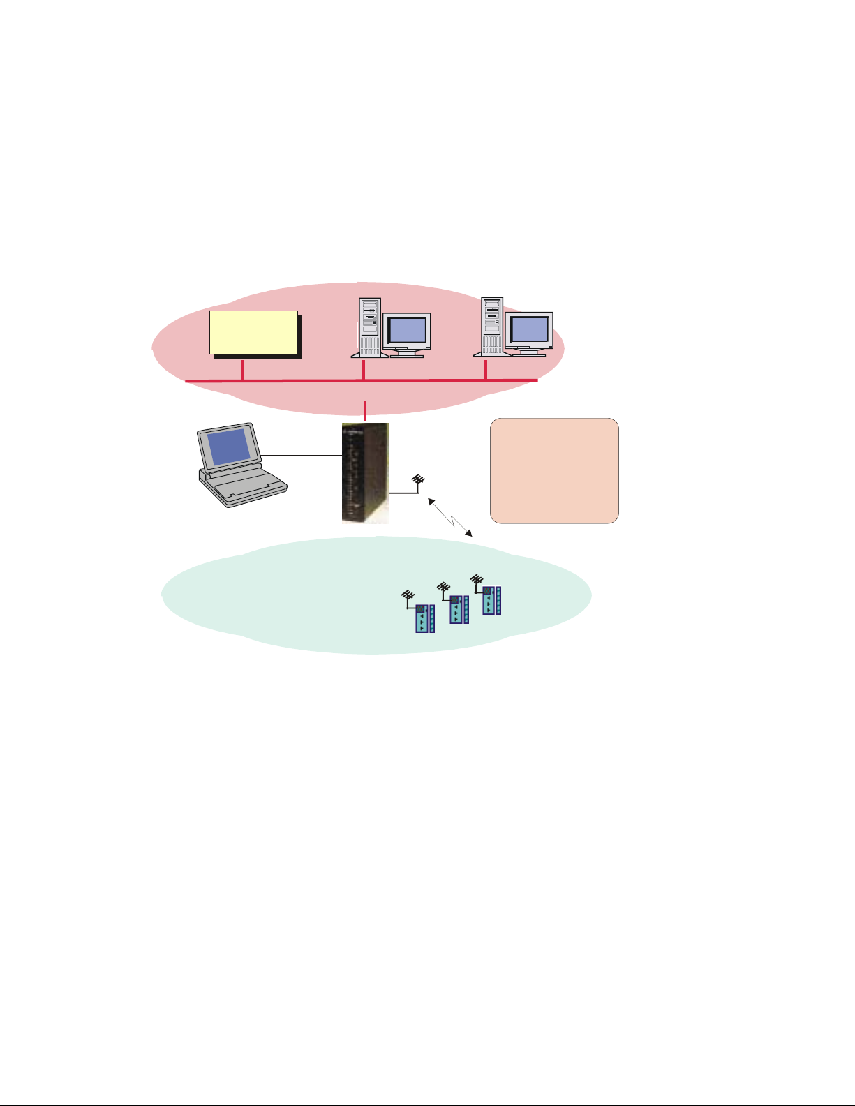
Introducing the IP Gateway
The IP Gateway for SCADA and NFM systems is a smart unit, based on the Motorola 68360
microprocessor and includes on-board memory, communication channels, indicator LEDs and
other circuits. It provides the SCADA and NFM software with access to the MOSCAD system,
based on the seven layers of the MDLC protocol, in order to exchange data with the RTUs. A
typical example of the IP Gateway is shown in Figure 1-1; a SCADA control center is
connected via the IP Gateway to a radio link of the MOSCAD system.
SCADA
Computer
TCP/IP on Ethernet
Introduction
Work Stations
MOSCAD
ToolBox
RS232
IP Gateway
Your gateway into the
MOSCAD world
MDLC on Radio
MOSCAD
RTU
RTU
RTU
Figure 1-1: MOSCAD System with IP Gateway, General View
1-2
Page 18
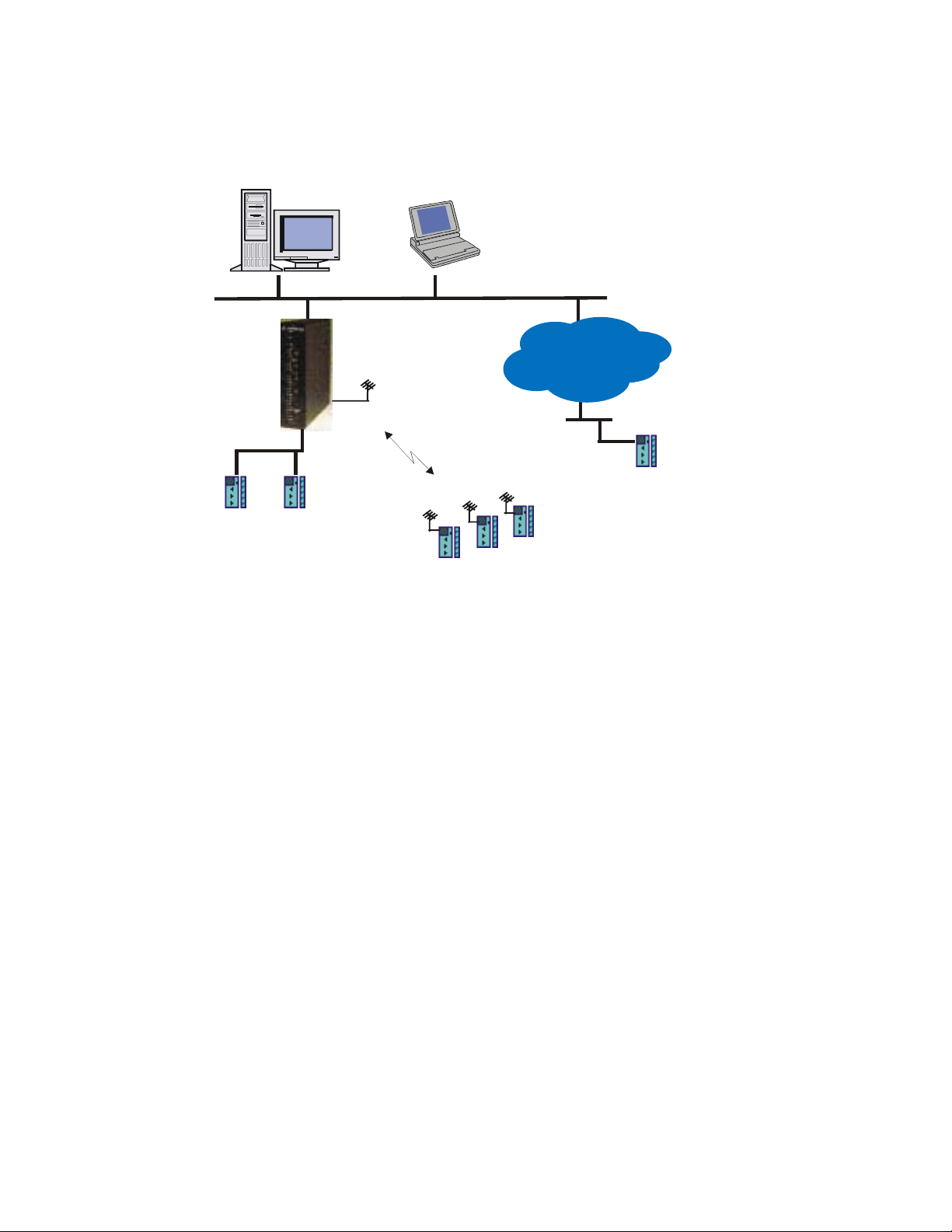
Introduction
A system with multiple vendors SCADA control center is shown in Figure 1-2. The MDLC
communicates with any SCADA computer which supports the TCP/IP network (UNIX, VMS,
Windows/NT, Windows/95, OS/2 etc.).
NFM Central MOSCAD
ToolBox
(over IP)
Ethernet
TCP/IP
MDLC over R 485S
IP Gateway
MDLC over Radio
RTU
RTU
IP Network
MDLC over IP
RTU
Ethernet
RTU
Figure 1-2: IP Gateway with Multiple Vendors SCADA Control Center
The SCADA control center, which includes workstations and a SCADA computer, exchanges
data with the MOSCAD system via the IP Gateway, which serves as a Gateway from the
TCP/IP world to the MDLC world. There are many SCADA packages which already have the
Gateway Interface driver implemented, some as direct access to the IP Gateway, and some as
OPC server.
IP Gateway Applications
The IP Gateway uses the TCP/IP LAN Protocol for exchanging data application messages with
the SCADA software. The IP Gateway API (Application Programming Interface) source
library allows SCADA developers to quickly and easily connect to the MOSCAD world. The
IP Gateway API, which is part of the IP Gateway product line, allows SCADA driver
developers to quickly and easily build the IP Gateway Interface (driver), which serves as a
communication interface with the MOSCAD world.
Data exchange between the SCADA (client) and the IP Gateway (server) is carried out using
"peer -to-peer" communication over the LAN. The IP Gateway can support multiple
connections that are initiated from multiple SCADA computers.
The implementation of the IP Gateway interface in the SCADA software allows the SCADA
to perform the following:
• Poll a MOSCAD RTU in order to get data and COS (Change-of-State) events from the
RTU tables.
1-3
Page 19

Introduction
• Send commands to the MOSCAD RTU and download parameters to its local process.
• Send commands via broadcasts to any required group of RTUs.
• Download parameters (set-points) to the RTU local process.
• Receive spontaneous reports (by contention) from RTUs (both burst and event
transmission).
• Receive time-tagged events logged in the RTUs (1 msec resolution).
• Adjust the RTU clocks (1 sec resolution).
• Synchronize the RTU clocks (1 msec resolution), using an external CPU with GPS.
• Support redundant IP Gateway configuration.
• Set the Gateway mode (Primary/Secondary).
• Retrieve Gateway status.
• Retrieve RTU links status.
MOSCAD NFM Overview
The MOSCAD NFM system provides communication providers with a solution for
supervising and controlling the operation of conventional and trunked radio, analog and digital
cellular, microwave radio and wireline telecommunication systems.
The MOSCAD NFM system provides the Network Management Center (NMC) with access to
the communication and environmental devices and gives the operator and the system manager
the tools needed to identify and fix faults within the communication system.
Figure 1-3 describes the general architecture of the MOSCAD NFM, which includes control
center workstations and computers that exchange data with the IP Gateway, allowing the NMC
to monitor and control non-SNMP devices at the communication sites.
1-4
Page 20
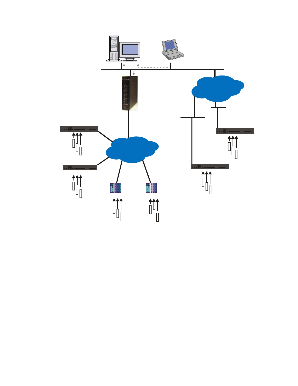
Introduction
MOSCAD NFM RTUMOSCAD NFM RTU
Network
Network
Elements
Elements
MOSCAD NFM RTU
Network
Elements
NFM Central MOSCAD
SNMP
TCP/IP
MDLC Network
MOSCAD RTU
IP Gateway
(Proxy MIB)
MOSCAD RTU
ToolBox
(over IP)
Ethernet
SNMP
Network
Elements
Ethernet
IP Network
Ethernet
MOSCAD NFM RTU
Network
Elements
MOSCAD NFM RTU
Network
Elements
Network
Elements
Figure 1-3: General Architecture of the MOSCAD NFM System
The MOSCAD NFM via the IP Gateway allows the system to offer SNMP (Simple Network
Management Protocol) connectivity, therefore providing a standard interface to a wide range
of NMC platforms (such as HP/OpenView, SUN/Solstice, IBM/NetView etc.).
The MOSCAD Remote Terminal Unit (RTU) represents the Element Level of the network
management model. It collects the various inputs, outputs and analog signals via a variety of
input/output (I/O) modules. In addition, the MOSCAD RTU serially interfaces to
communication devices (radio, cellular and telecommunication) and is able to emulate (speak)
their ASCII based native protocol, allowing the MOSCAD to not only monitor alarms, but to
configure and change parameters as well.
1-5
Page 21

IP Gateway System Overview
SCADA System
The complete control system is comprised of the SCADA control center (or centers)
communicating with MOSCAD RTUs over various communication links, such as:
• conventional radio
• trunked radio
• data radio, dial-up lines
• leased lines,
• microwave, fiber optic links
• combined networks
The communication system is used for transmitting alarms, status and telemetry, calculated
data diagnostics and error logging information from the MOSCAD RTUs to the central facility
computer and vice versa. It is also used for downloading, monitoring and debugging the
application program at the sites.
The system may be relatively simple, comprising several RTUs and a single control center, or
a more complicated hierarchical system, where several sub-control-centers communicate with
lower, parallel and higher hierarchies. The RTUs may also communicate with each other
and/or with any other hierarchy in the system.
The MOSCAD system uses the MDLC protocol, based on the seven layers of the OSI model
published by ISO, and adapted for SCADA communications. It provides network support,
multiple logical channels per physical port, allowing each RTU to simultaneously run several
communication sessions, such as data exchange, on-line monitoring, diagnostics, etc.
The MOSCAD system is supplied with a Toolbox, which is a software package that runs on an
IBM PC (or compatible). All RTU functions such as configuration, database and process
definition, downloading, monitoring, hardware and software diagnostics, etc. are defined by
means of the MOSCAD Programming Toolbox.
Figure 2-1 describes a typical MOSCAD radio system. The IP Gateway includes one Ethernet
port for connection to the SCADA computer and 3 serial ports for communicating via MDLC
protocol to the MOSCAD devices. In this particular case, one MDLC port is connected to the
MOSCAD Programming Toolbox and the second MDLC port is connected to a radio for
communicating with the RTUs.
2-1
Page 22
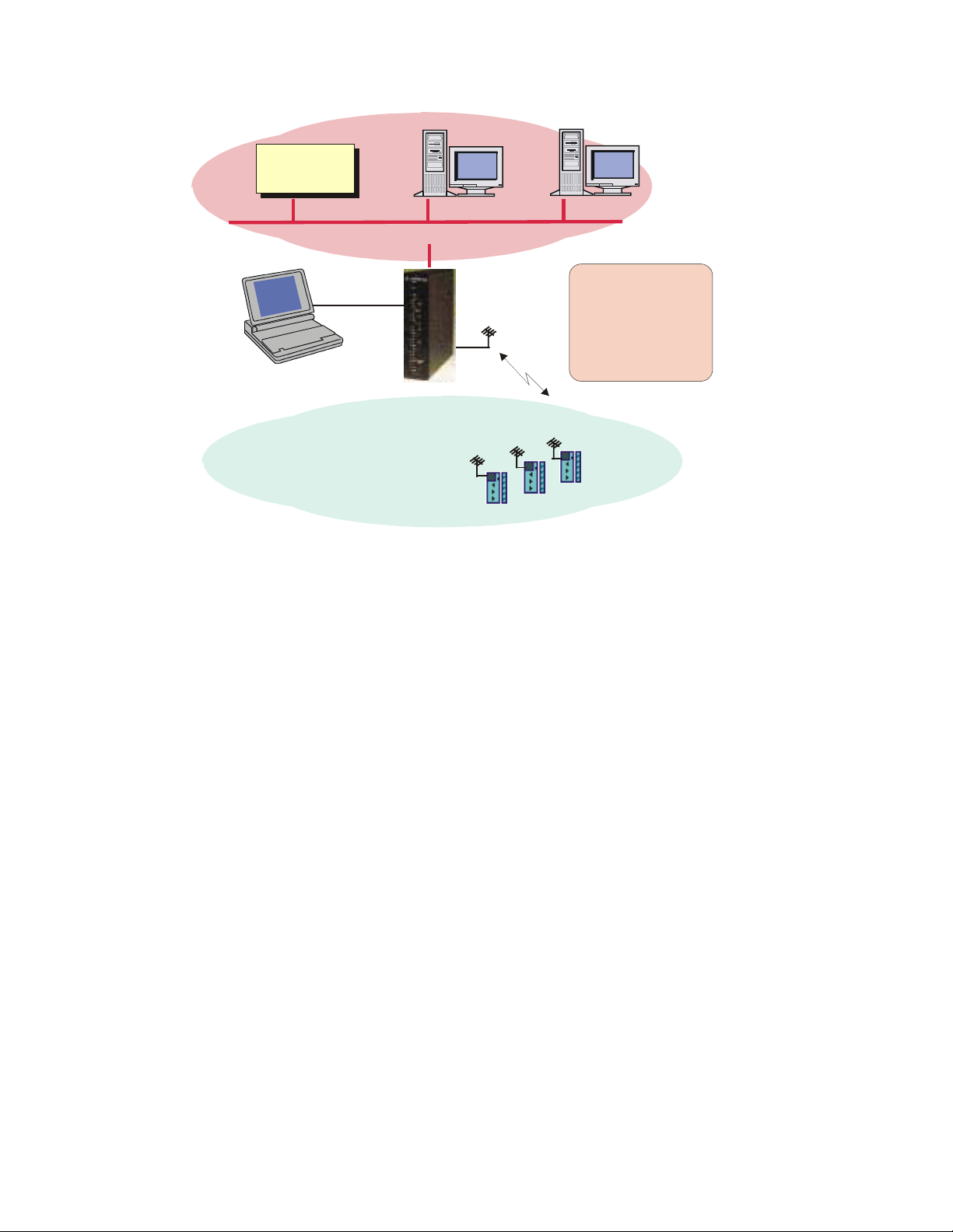
SCADA
Computer
System Overview
Work Stations
TCP/IP on Ethernet
MOSCAD
ToolBox
RS232
IP Gateway
Y our gat e wa y int o th e
MOSCAD world
MDLC on Radio
MOSCAD
RTU
RTU
RTU
Figure 2-1: SCADA Control Center with Radio-Based MOSCAD System
2-2
Page 23
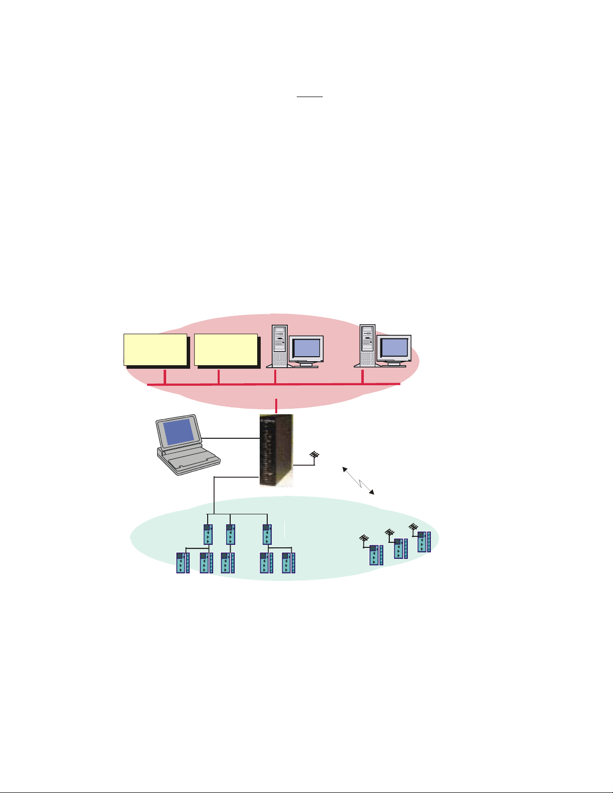
System Overview
The IP Gateway allows the SCADA center to conduct a large number of sessions via a large
number of logical channels in spite of a single physical RS-232 port. The IP Gateway also
serves as an MDLC router between the MOSCAD Programming Toolbox and RTUs.
The Toolbox may be connected either locally to an RTU or via the MDLC port of the IP
Gateway to any RTU in the system. All programming and monitoring functions can be
performed either locally or remotely.
Note: The MOSCAD Programming Toolbox that is connected locally to one of the RTUs in
the system can service any other RTU in the system via the communication network.
Figure 2-2 describes multiple SCADA control centers which are connected to the IP Gateway
via a 10 Mbps Ethernet LAN. In this case, multiple TCP/IP logical links are used for
communicating with the IP Gateway, which is connected via multiple MOSCAD CPUs to
multiple MDLC links (Radio link, Line link, Dial-up link etc.).
Multiple SCADA control centers can simultaneously perform multiple sessions with the IP
Gateway in order to send commands and polling requests to the RTUs and to receive data and
contention reports from the MOSCAD RTUs.
SCADA
Computer
SCADA
Computer
Work Stations
TCP/IP on Ethernet
MOSCAD
ToolBox
Wire Line Dial up Modem
RTU
RTU RTU RTU RTU
RS232
MDLC on R 485S
Leased
Line
MOSCAD
MDLC on Radio
RTU
RTU
RTU
Figure 2-2: SCADA Control Center with Multiple Links-Based MOSCAD System
2-3
Page 24

MDLC Over IP
MOSCAD RTUs and IP Gateways can use IP (Internet Protocol) technology to interface to
advanced radio infrastructure (e.g. digital ASTRO IP conventional systems) and to standard
private IP networks. Most benefits of the MDLC protocol are preserved. MDLC and IP
networks can be integrated in the same system, as networking properties are preserved.
MOSCAD MDLC applications need not be modified as the lower layers of the protocol
support IP.
MDLC packets to be transmitted are enveloped inside IP datagrams and sent between remote
RTUs or between an IP Gateway and an RTU.
An IP Gateway can act as a gateway between the field and the SCADA Central to extract the
enveloped frames from the IP message. A ToolBox can be connected to one of the RTUs or to
the IP Gateway, either locally or over IP network.
Each RTU/IP Gateway is assigned a Site ID. In addition, each RTU/IP Gateway with an IP
interface is assigned an IP address. An IP conversion table which maps Site IDs to IP
addresses is created in the ToolBox and downloaded to the RTUs and IP Gateway. This
enables routing over the IP network to the proper destination.
Two variations of MDLC over IP exist, MDLC via Terminal Server and MDLC via Astro IP.
System Overview
MDLC via Terminal Server
If the RTUs are on a Local Area Network (LAN), each can be connected to a Terminal Server
attached to the Ethernet. The Terminal Server converts the RS232 to the Ethernet LAN and
enables communication with an IP Gateway, or between RTUs.
In the diagram below, a typical configuration is shown, with RTUs attached via SLIP (Serial
Line IP) port to a Terminal Server, which is in turn attached to Ethernet.
2-4
Page 25
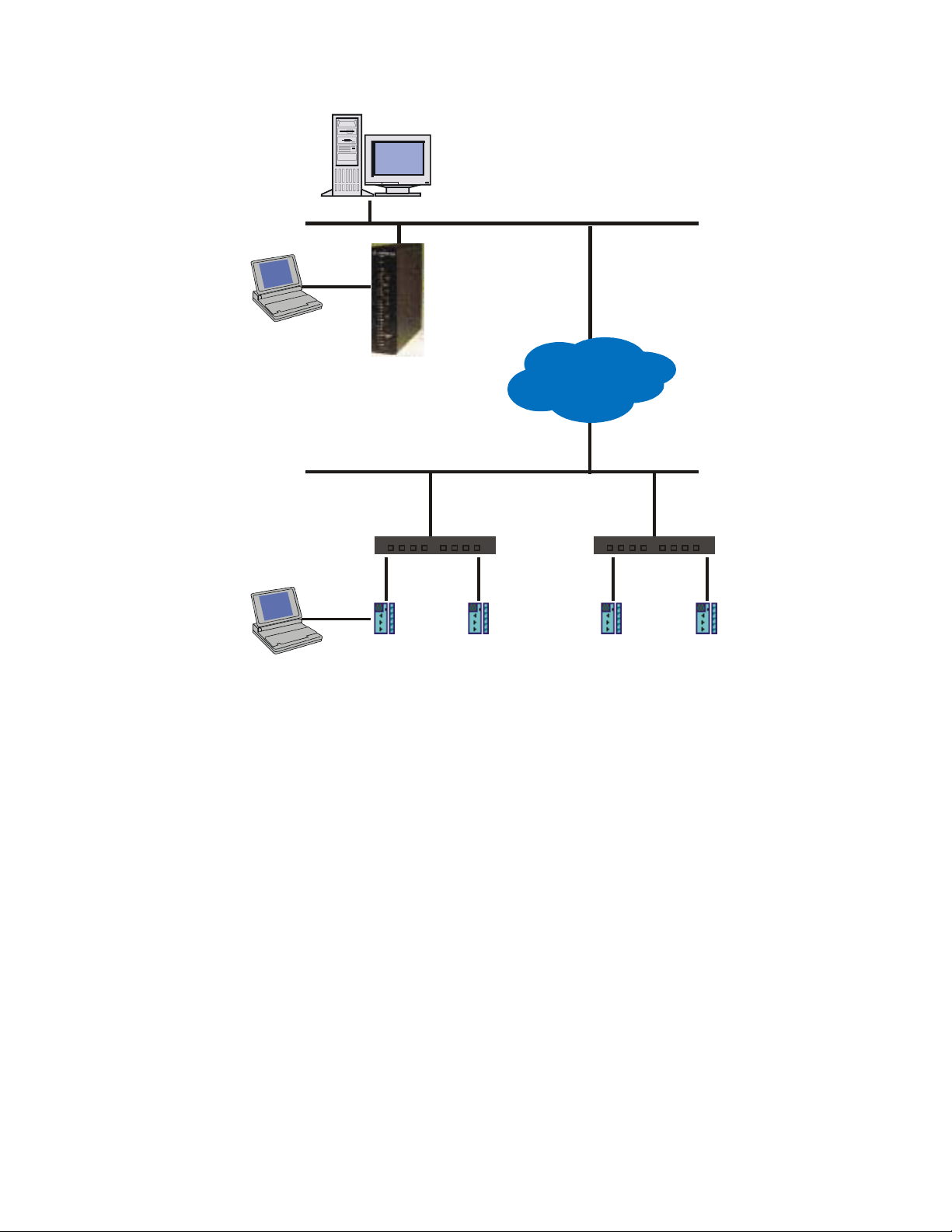
IP Gateway
ToolBox
(over IP)
SCADA Central
LINE 1
RS232
MDLC Network
System Overview
Ethernet
IP Gateway
(Proxy MIB)
IP Network
Ethernet
MOSCAD
Programming
ToolBox
(over IP)
Figure 2-3: Typical Configuration, MDLC via Terminal Server
MDLC via Astro IP
RTUs can be connected via SLIP connection to an ASTRO radio, which is part of an IP
network.
In the diagram below, a typical configuration is shown, with RTUs attached via SLIP over
RS232-E to ASTRO SPECTRA radios which support IP data capability. A ToolBox is
connected to one of the RTUs through either Port 2 or Port 3. The IP Gateway on Ethernet
acts as a gateway, translating between the IP and MDLC protocols.
RS232
Terminal Server
LINE 1 LINE 1 LINE 1 LINE 1
MOSCAD
RTU IP1
MOSCAD
RTU IP2
MOSCAD
RTU IP3
Terminal Server
MOSCAD
RTU IP4
2-5
Page 26
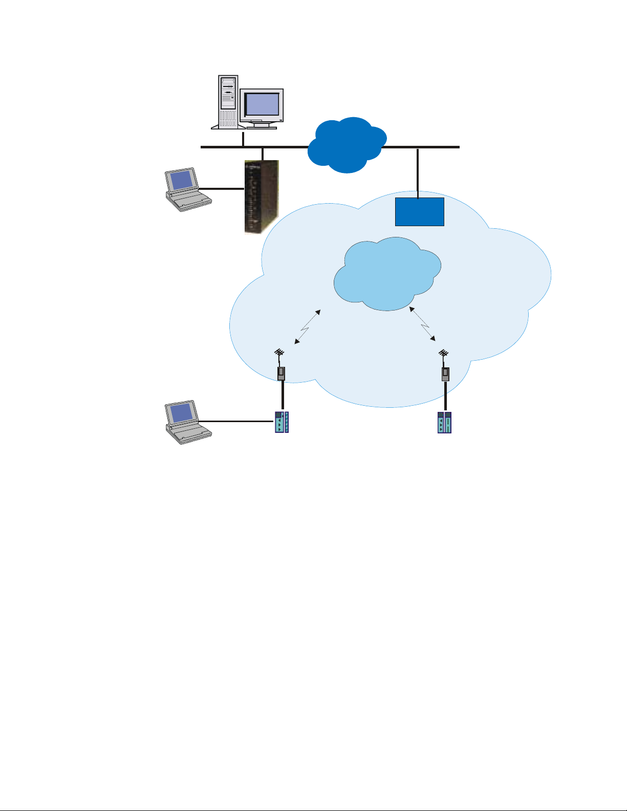
SCADA Central
A
System Overview
IP Gateway
ToolBox
(over IP)
MOSCAD
Programming
ToolBox
(over IP)
LINE 1
RS232
RS232
IP Cloud
IP Gateway
ASTRO Spectra Radio
LINE 1
SLIP
Connection
STRO RF
System
Ethernet
RNC
IP Network
ASTRO Spectra Radio
LINE 1
SLIP
Connection
Figure 2-4: Typical Configuration, MDLC via Astro IP
MDLC Over Private DataTac
MOSCAD RTUs can communicate over Private DataTac systems (RDLAP) with SCADA
centrals and with other RTUs. All MDLC features are preserved except for clock
synchronization.
RTUs are connected to RDLAP (DataTac) radios (e.g. VRM 500, 600, 650, 660, and TRM
660) via RS232. An RTU sends a message (MDLC), through the radio to the Radio Network
Controller (RNC). The RNC encapsulates the MDLC message and send it over IP to the IP
Gateway. The IP Gateway then extracts the MDLC message from the IP envelope and
transmits it to the appropriate destination. If the destination is another RTU over Private
DataTac, the IP Gateway must support the reflector feature, which enables it to “reflect” the
message back over RDLAP (DataTac).
MOSCAD
RTU
MOSCAD-L
RTU
2-6
Page 27
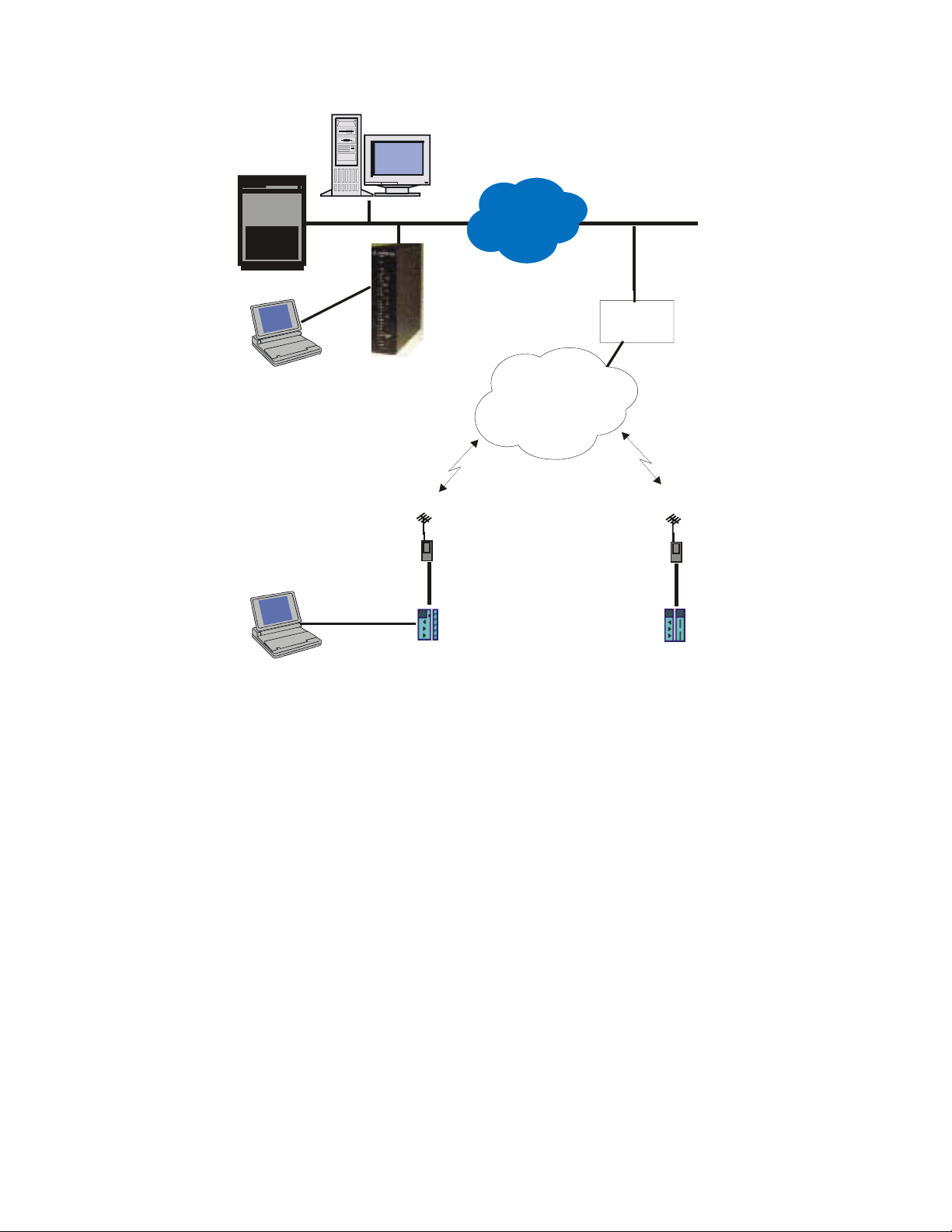
Host
Computer
System Overview
SCADA Central
IP Gateway
ToolBox
(over IP)
MOSCAD
Programming
ToolBox
(over IP)
LINE 1
RS232
RS232
IP Gateway
with
Reflector
Private DataTAC Radio
RS232
MOSCAD
RTU
IP Cloud
RF System
Ethernet
RNC
Private DataTAC Radio
RS232
MOSCAD-L
RTU
Figure 2-5: Typical Configuration, MDLC via Private DataTac radios.
The picture above shows a typical system which supports MDLC communication over RDLAP
(DataTac) radios. Note that the IP Gateway is configured as RDLAP (DataTac) reflector. A
host computer attached to the Ethernet can receive TCP/IP applications from non-MOSCAD
terminals on existing RDLAP (DataTac) systems, if required. A MOSCAD Programming
ToolBox can be connected to one of the RTUs, and can access another RTU by using its Site
ID and Link ID. ToolBox can also be attached to one of the serial ports of the IP Gateway.
SCADA Interface
Client-Server environment
The SCADA application for the IP Gateway is based on a client-server approach.
The IP Gateway application acts as a server while the SCADA Interface acts as a client. In
such a relationship, the SCADA Interface must establish the connections with the IP Gateway
needed for communicating with the MOSCAD RTUs.
After the connections have been established, the SCADA Interface can send data, commands,
and polling requests to the field RTUs. It can also establish a special connection that enables
2-7
Page 28

System Overview
receipt of data transmissions initiated by the field RTUs (so called burst/RTU event data,
contention data or Change-Of-State [COS] messages).
A specialized routine, API CONNECT, allows the SCADA Interface to establish the most
fitting mode of communication with the IP Gateway, based on the existing SCADA
communication mode.
Channels and Channel types
The SCADA Interface must establish at least one connection toward the IP Gateway server.
These connections are called channels and are used to transfer messages from the SCADA
center toward both the Gateway and the RTUs in the field. The client application can open
different types of channels to best serve its SCADA Interface process.
The two basic channel types are:
• Regular
• Spontaneous
A Regular channel enables asynchronous sending/receiving of data and requests. It uses
amailbox mechanism for mapping the request messages to their replies.
A Spontaneous channel allows receiving burst data (Spontaneous COS messages) and RTU
events - i.e. transmissions initiated by the field RTUs. This feature almost eliminates the need
for the SCADA application to poll data since every change in one of the telemetry field
variables can immediately be transmitted to the SCADA application.
MOSCAD System - RTU definitions
To make the MOSCAD field system definition transparent to the SCADA client application
and to correctly parse the data received from the MOSCAD system, the API builds an internal
data structure defining the types and numbers of the field RTUs. To do so, it uses two external
system definition files (in ASCII format).
This automatic system definition done by the API routines hides the field system structure
from the SCADA application and eliminates the need for any application modifications when
working with different MOSCAD systems. Moreover, new RTUs can be added to the system
at run time using the appropriate API routine.
Primary/Secondary Gateway Modes
The IP Gateway supports a redundant configuration. There are two modes of operation:
Primary and Secondary. The initial mode of operation is defined by the startup process of the
IP Gateway. At any other time, the SCADA can change the mode of operation flexibly by
calling the appropriate API set mode routine. The API also supplies a routine for checking the
current mode of operation. This functionality of the IP Gateway provides redundant gateway
operation, which minimizes the risk of communication failure.
2-8
Page 29

System Overview
Communicating with the IP Gateway
Once a channel has been established with the IP Gateway, the SCADA interface can issue
requests to the IP Gateway. The request categories are Send routines, Receive routines, Data
Analysis routines and Management routines.
Typical API sequence calls are the following:
Connect /* Establish Connection to Gateway. */
Poll /* Send a polling request. */
Receive /* Receive MDLC communication (answer) buffer. */
Get_next_message /* Extract one message from the MDLC communication buffer. */
Get_next_data_entity/* Get one data entity from the message buffer. */
Troubleshooting
The IP Gateway handles the communication with the SCADA in the REQMNG device.
Diagnostics on this device can help when troubleshooting the SCADA connectivity.
For more information on the REQMNG device, see the Software Diagnostics Output section.
2-9
Page 30

MOSCAD NFM System
A typical network management system can be divided into three main levels:
• Network Management Level
• Element Manager Level
• Element Level
The following section provides a brief description of the MOSCAD NFM components that
allow managing and supporting these network management levels.
Figure 2-6 shows a typical MOSCAD NFM configuration including all network management
levels. It describes the MOSCAD NFM architecture that includes NMC computers and
workstations that monitor and control - via the IP Gateway and the NFM RTUs - non-SNMP
devices at the communication sites.
In this configuration, the end devices at the communication sites serve as a NE (Network
Element) and the NFM RTU serves as an Element Manager that monitors and controls multicommunication and environmental devices at the site. The IP Gateway allows monitoring and
controlling devices - via the NFM RTU - that are installed at multiple communication sites.
The NMC allows monitoring and controlling of all devices in the network via multiple IP
Gateways.
System Overview
The NMC application can use the SNMP protocol and the IP Gateway MIB to Auto-discover
the IP Gateway, the communication sites as well as the devices and their objects.
By using this MIB, the NMC application can poll the devices and their objects (NEs and their
objects) in order to refresh its database and to display unsolicited events (Traps ) in the Alarm
Manager application. By using the TELNET application in the host, the operator can access
via the IP Gateway and the NM RTU any communication devices that have an RS-232 port
with interactive interface.
The MOSCAD NFM product can be integrated either with the Motorola PRN (Private Radio
Network) architecture or with a third party communication/telecommunication system via an
IP Gateway that gives the NMC applications access to the equipment and environmental
devices at the sites.
2-10
Page 31

System Overview
System Support CenterNetwork Management Cente r
Telnet
Work Station
Communication Site
R485S
EMU EMU EMU
ENVIRONMENTAL
SENSORS
. . .
LEGEND
Device
Application
SC
EMU
Site
Concentrator
Element
Management
Unit
TCP/IP on Ethernet
Terminal Server
. . .
132
MDLC
SC
DEVICEWDEVICE
X
Communication Site
R 485S
. . .
EMU EMU EMU
ENVIRONMENTAL
SENSORS
MDLC
SC
DEVICEYDEVICE
Z
RS232
MDLC Network
Communication Site
R 485S
EMU EMU EMU
ENVIRONMENTAL
SENSORS
. . .
MOSCAD
ToolBox
MDLC
SC
DEVICEYDEVICE
Z
Figure 2-6: MOSCAD NFM System Architecture with TELNET Application
2-11
Page 32

MOSCAD RTU
The MOSCAD RTU is a smart modular unit designed to operate as a stand-alone controller or
as part of a system having any number of RTUs, control centers and sub-centers connected
through a communication network with any number of links and nodes.
The MOSCAD RTU must be configured and loaded with the appropriate application using the
MOSCAD Programming Toolbox.
The MOSCAD RTU is a microprocessor-based unit, which basically consists of a CPU
module and various I/O and communication modules. A wide range of I/O and communication
modules makes the MOSCAD system flexible to meet most application requirements.
For further details on the MOSCAD RTU, refer to the MOSCAD Owner’s Manual and the
MOSCAD Service Manual.
MOSCAD Toolbox
The MOSCAD Programming Toolbox software package allows the system engineer to define
and maintain the MOSCAD system according to user needs and requirements. The following
main functions may be performed by means of the MOSCAD Programming Toolbox:
System Overview
1. Editing the RTU user program including the following:
• Site Configuration according to hardware and port configuration
• Network Configuration according to network configuration
• Application database
• Application process
2. Preparing project documentation for the user
3. Automatically creating a central file to be used later during RTU database creation in the
SCADA control center
4. Downloading Site Configuration to the MOSCAD RTU via the RS-232 port of the unit
5. Performing the following functions on any MOSCAD RTU either via local connection or
via the communication network:
• Uploading Site Configuration and related data
• Downloading Application Program and Network Configuration
• Real-time symbolic (graphic) monitoring and debugging of the application (both
database and process)
• Updating time and date at RTU sites
2-12
Page 33

System Overview
• Testing all hardware modules, including software calibration of analog inputs and
outputs
• Retrieving time-tagged events (of down to 1mSec resolution) logged in the RTUs
• Synchronizing the RTU real-time clock
• Retrieving errors logged in the RTUs (hardware or software malfunctions)
• Capturing the data packets on the communication links and analyzing the protocol
seven layer
• System software diagnostics by object entity names
The definition of the RTU application program allows the system engineer to build the RTU’s
database in a tabular form as a set of tables. The same tables used for the RTU database
definition are the basis for process programming, I/O link definition, automatic central
database definition, real-time monitoring of RTU operation, etc.
Once the database is built, the RTU programming process is carried out by using the symbolic
Motorola Advanced Ladder Diagram Language.
IP Gateway for TCP/IP
The IP Gateway hardware is based on the 68360 Motorola microprocessor, which is a smart
CPU with Ethernet and an I/O controller. It includes support for TCP/IP over an Ethernet port
(10Base-T and AUI connectors) for communication with the SCADA, and three serial ports
for communication with the Toolbox and with the MOSCAD RTUs.
The IP Gateway includes 22 LEDs, located on its front panel which indicate hardware status
and communication port activity. In case of a malfunction, see the Indication LEDs section in
the Hardware Installation section of this manual.
Two Ethernet connectors give support for connection to either a Twisted-Pair Ethernet cable
(via 8-pin RJ45 connector) or a Thick-Wire Ethernet cable (via 15-pin AUI connector). To
connect a Thin-Wire coaxial cable to the IP Gateway, a Thin-Wire to AUI connector unit
which allows connecting the coaxial cable to the AUI port, should be used (not supplied).
The IP Gateway software provides MDLC services to the SCADA
The MDLC application layer is used for receiving events, status and telemetry calculated data
from the MOSCAD RTUs to the SCADA
and process parameters from the SCADA central to the MOSCAD RTUs. The IP Gateway
software includes the TCP/IP driver for communicating with the SCADA computers and the
MDLC driver for communicating with the MOSCAD RTUs as well as with the MOSCAD
Programming Toolbox.
control center applications.
central applications. It is also used to send controls
2-13
Page 34

IP Gateway Toolbox
The IP Gateway Toolbox is a software package, which runs on an IBM PC (or compatible),
and allows the user to build the configuration for the MDLC and TCP/IP drivers. It also
enables the user to download it to the IP Gateway hardware.
The IP Gateway Toolbox features the following:
• Microsoft Windows Man Machine Interface (MMI).
• Graphical User Interface (GUI). Each Toolbox module is represented by an icon, enabling
friendly user access.
• Receiving errors logged in the system from the IP Gateway and the RTUs.
• Receiving communication diagnostics from the RTUs and operation diagnostics from the IP
Gateway.
• Setting IP Gateway or RTU time and date.
• Downloading of user selected definitions/configurations to the IP Gateway.
• Erase Flash and System Download – enables the user to erase and download specific
system partitions.
System Overview
• Links Configurator – enables the user to change the number of links assigned to each
medium.
The IP Gateway Toolbox allows the user to set, modify and download the following four basic
groups of parameters:
• TCP/IP driver (IP address)
• IP Gateway configuration (IP Gateway Site ID and Link ID)
• MDLC Network configuration (system-wide MDLC routers)
• MDLC Sites Table (system-wide Site ID and Link IDs)
IP Gateway Web Server
The IP Gateway, version 4.0 and higher, includes a built-in Web Server. The Web server
enables users to perform certain Toolbox operations and to convey site information to and
from the technicians, regardless of where they are located, over the World Wide Web.
The IP Gateway Toolbox utilities available through the Web Server enable the user to
remotely perform the following operations:
• Provide reports on the status of each device in the current IP Interface or Gateway, as well
as historical and statistical data on the device activities.
2-14
Page 35

• Remotely define SNMP and Motorola SSC parameters.
• Erase the IP Interface/Gateway Flash memory and downloads a new system.
IP Gateway Redundancy
To minimize the risk of a SCADA control center single point of failure and to ensure high
availability for its applications, a redundant IP Gateway can be configured. When one
IP Gateway is not available, a second, redundant IP Gateway can be used. To increase the
availability of the LAN network, dual Ethernet segments can be used, and each IP Gateway
can be connected to a different segment.
In a redundant IP Gateway system configuration, one IP Gateway acts as the primary unit.
The primary IP Gateway communicates properly over MDLC communication and over the
SCADA channels. There is bi-directional transfer of both SCADA application messages and
IP Gateway management messages. The secondary IP Gateway transfers IP Gateway
management messages only. (It does not send or receive any MDLC messages, since it is
logically disconnected from the link.)
System Overview
HealthCheck Mechanism
The IP Gateway system includes a HealthCheck mechanism which manages the MDLC
connectivity to the sites. Associated with each site are two links, through which the site can be
reached. A background mechanism in both the IP Gateway and the MOSCAD units constantly
verifies which links are available.
The HealthCheck mechanism uses the site table as the basis for its operations. As the
IP Gateway identifies which links are available, it can reduce communication overhead by
routing frames destined to sites through their operational links.
2-15
Page 36

Hardware Installation
N
Hardware description
The IP Gateway hardware is based on the 68360 Motorola processor, which is a dedicated
smart CPU with Ethernet and I/O controller. In addition to the communication capabilities, the
IP Gateway has powerful processing capabilities, using 32 Mbytes (8 Mbytes X 32 bit) of
DRAM and 1 Mbyte (256 Kbyte X 32 bit) of FLASH memory.
A simplified block diagram of the IP Gateway hardware is provided in Figure 3-1.
DRAM
1M X 32 BIT
FLASH MEMORY
256K X 32 BIT
1M X 32 BIT
FRONT PANEL
LEDs
INDICATIONS
CPU
68360
INDICATIONS
ETHERNET
TRANSCEIVER
RS-232
TRANSCEIVER
RS-232
TRANSCEIVER
RS-485
TRANSCEIVER
RS-232
TRANSCEIVER
PLUG-IN BOARD
MODEM
TRANSCEIVER
PLUG-I
BOARD
PORT1A
PORT1B
PORT1C
PORT2A
PORT2B
PORT3
PORT4
Figure 3-1: IP Gateway, Simplified Block Diagram
3-1
Page 37

Communication Ports
The IP Gateway includes support for TCP/IP over 10 Mbits/sec Ethernet LANs for
communication with the SCADA, and three serial ports for MDLC over various links (radio,
dialup and dedicated lines, multidrop wireline, serial RS-232 or RS-485) for communication
with the MOSCAD RTUs.
The IP Gateway supports multiple logical channels running the TCP/IP protocol over
Ethernet, thus allowing multiple processes running on the SCADA computer, to
simultaneously access a number of functions in the IP Gateway.
The IP Gateway software supports four communication channels that can be configured to
support the following links:
Port 1 A - Ethernet - 8-pin RJ45 connector, twisted-pair (TP)
Port 1 B - Ethernet - 15-pin AUI connector
Port 1 C - RS-232
Port 2 A - RS-485
Hardware Installation
Port 2 B - RS-232
Port 3 - According to the plug-in board (see table below)
Port 4 - According to the plug-in board (see table below)
Ports 3 and 4 are available with one of the following options:
Model/Option BoardFor ... Plug-in
Factory
Installed
VHF/UHF Conventional FSK V356 FRN 5614
VHF/UHF Conventional DFM V390 FRN 5546
UHF + Single-site trunking
Multi-site UHF/860MHz
trunking radio
Serial Port RS-232 V345 FRN5724
Line Modem 2400 bps Dial-up/Dedicated V226
DPSK V370 FRN 5708
V404
Installed
FRN 5639
Field
Line Modem 1200 bps Dial-up/Dedicated V219
V285
FRN 5669
Note: The same plug-in boards that are used for the MOSCAD are used in the IP Gateway.
3-2
Page 38

Hardware Installation
The third and fourth channels can be connected via plug-in board to various communication
media:
Radio: VHF or UHF, conventional or trunked radio, that support the following
characteristics:
• FSK up to 2.4 kbps
• DPSK @ 1.2 kbps
• DFM @ up to 4.8 kbps
Wireline: Supports the following modem and their characteristics:
• Leased 2 or 4 wire, up to 2.4 kbps, Sync and Async
• V.22, V.22 bis, Bell 212, Bell 102
• Multidrop 2-wire, up to 1.2 kbps, Sync
• Dial-up, up to 2.4 kbps, Async, V.22, V.22 bis, Bell 212
• RS-232 Async, up to 57.6 kbps
3-3
Page 39

Mechanical Installation
The IP Gateway unit can be supplied with the following two configurations:
Gateway with communication interface
In this configuration, the Gateway is mounted in an NEMA4 housing, suitable for wall
mounting and composed of the following:
• Stand-alone Gateway unit
• Radio unit applicable for the required frequency range and power, or alternatively, line
unit applicable for interfacing to dedicated or dial-up lines.
• A 110V AC power supply + charger (produces +12V DC for the Gateway’s logic board
and charges the battery); a 220V AC power supply is available as an option.
• 12V DC battery rated for 5 Ah operation (10Ah battery is available as an option).
Hardware Installation
Figure 3-2: IP Gateway with Communication Interface
3-4
Page 40

Hardware Installation
Stand-alone Gateway unit
The IP Gateway desk-top unit without radio, PS/Charger and box, to be placed on a desk or
installed in the central facility by the user. The user must supply 12V DC.
Figure 3-3: Stand-alone IP Gateway
3-5
Page 41

Connectors
Connector Locations
Eight connectors are located on the IP Gateway rear panel as shown in Figure 3-4 below:
Figure 3-4: IP Gateway Rear Panel
Connector Description
The following table lists the IP Gateway’s connectors and their connection points:
Hardware Installation
Connector Type/Usage Pin
No.
Power 4 pin Male
Connector/
AC Power
Port 2B RS-232 1
Port 2A RS-485 1
Port 1C RS-232 1
1
2
3
4
2
3
4
5
6
7
8
2
3
4
2
3
4
Signal Name
Relay
Vin
P.GND
GND
TXD
RXD
CTS
P.GND
CD
RTS
CNTRL
DTR
+12V
DO_/rI_
DO / RI
P.GND
TXD
RXD
CTS
P.GND
3-6
Page 42

Port 1B AUI /
Ethernet
Port 1A RJ45 /
Ethernet
10
11
12
13
14
15
Hardware Installation
5
CD
6
RTS
7
CNTRL
8
DTR
1
GND
2
COL+
3
DO+
4
GND
5
DI+
6
GND
7
N.C
8
GND
9
COLDOGND
DI+12V
GND
N.C
1
TD+
2
TD-
3
RD+
4
N.C
5
N.C
6
RD-
7
N.C
8
N.C
For connection of Port 3 and 4, refer to the J4 connector in the MOSCAD CPU Module in the
MOSCAD RTU Service Manual.
Port Specifications
Ethernet Port
Ethernet is a local area network (LAN) that allows the IP Gateway to communicate with
various computers and workstations at 10 Mbps. The connectivity of the IP Gateway to the
LAN infrastructure can be either twisted-pair, thick or thin-wire (coaxial) cable.
The IP Gateway includes two types of connectors for connection with the Ethernet port: AUI
and 10BaseT. Use either an RJ45 or AUI connector to connect your IP Gateway via either port
1A or port 1B, to Ethernet LAN.
3-7
Page 43

Use the “Thin-Wire to AUI” unit for connecting the IP Gateway to “Thin-Wire LAN” (coaxial
media.
A unique Ethernet port address is assigned by Motorola at the factory. This address is on a
sticker, placed on the Gateway main board (but you don’t need to know it to run the Gateway).
The IP address for the IP Gateway should be assigned by the network administrator and has to
be set via the IP Gateway Toolbox. Like the Ethernet address, the IP address should be a
unique number.
IP Gateway Toolbox Port
Connect Port 2B of the IP Gateway to the IP Gateway Toolbox. Use the FLN6457 adapter to
connect the PC serial ports (COM1 or COM2) to the Gateway.
IP Gateway/MOSCAD
Toolbox (PC)
Hardware Installation
IP Gateway
COM1 or
COM2
FLN6457
Figure 3-5: IP Gateway Toolbox Connection
If the RS-485 port (Port 2A) is required for communication with the field, use Port 3 for the
connection with the IP Gateway Toolbox. To introduce this change, connect the IP Gateway
Toolbox to Port 2B and use the Site Configuration program to change the default
configuration. Port 2A will now serve for communication over RS-485 with the field, and Port
3 will serve for communication over RS-232 with the PC.
After downloading the new configuration, you can use the IP Gateway Port 3 for connection to
the IP Gateway Toolbox (PC Port, COM1/COM2).
Always use Port 2B in order to erase and download a new Gateway software version (CODE)
or to erase and download the default configuration (CON) via your PC. Use this port also to
download a new Gateway configuration to your updated Gateway software, via your IP
Gateway Toolbox.
RS-232/RS-485 Communication Ports
For various radio or line communication configurations, first install the designated plug-in
board on Port 4 and run the Site Configuration program from your IP Gateway Toolbox in
order to configure the proper plug-in board.
Port 2B
Use an RS-232 MOSCAD cable, FLN6457A, to connect the IP Gateway (Port 2B or Ports 3
or 4) to the MOSCAD CPU.
Use an RS-485 MOSCAD Cable, FKN4400A, to connect the IP Gateway via Port 2A to the
MOSCAD CPUs for communication with the MOSCAD environment.
3-8
Page 44

Power Supply
The IP Gateway with connection interface is powered by the MOSCAD 12V power supply
(10.8 ÷ 15.1V DC). Connect a four-wire power cable - FKN4411A - from this power supply to
POWER on the rear panel.
The stand-alone Gateway is powered from an external +12V DC power supply.
Hardware Installation
3-9
Page 45

Indication LEDs
There are 22 indication LEDs located on the IP Gateway’s front panel. These LEDs provide an
indication of the board status and communication ports activity. Table 3-4 below describes
each indication. The front panel and LEDs are shown in Figure 3-6 below.
Indication Port Description
PWR The IP Gateway is DC powered.
RST A hardware or software reset is being executed.
DIAG An ERROR Message is pending in the Error-Logger.
TX Port 1
CM Port 1 RS-232 - Not supported
RX Port 1
TX Port 2 Data Transmission
CM Port 2 Busy Channel
Hardware Installation
RX Port 2 Data Reception
TX Port 3 Data Transmission
CM Port 3 Busy Channel
RX Port 3 Data Reception
TX Port 4 Data Transmission on port 4
CM Port 4 Busy Channel - port4
RX Port 4 Data Reception
TX Ethernet Data Transmission on Ethernet port
RX Data Reception on Ethernet p ort
COL A collision is sensed on the Ethernet lines.
TP The twisted pair port is selected (J6).
LI Link integrity is ok.
POL A reverse polari ty is sensed on the reception line.
JAB A jabber condition is sensed on the twisted pair lines.
Table 3-4: List of Indications
Note: When reverse polarity is detected on the reception lines (High and Low), the indication
POL is lit, but the reception is not disabled.
3-10
Page 46

Hardware Installation
Figure 3-6: IP Gateway Indication Panel
LEDs Combinations
A combination of lighted LEDs indicates a malfunction in the CPU. The nature of the
malfunction is indicated by the LEDs which light simultaneously with the DIAG LED, as
detailed below:
(DIAG LED is on):
• (1) CM LED is on: RAM test has failed.
3-11
Page 47

Hardware Installation
• (2) RX LED of Port 4 is on: ROM test has failed.
• (3) CM and RX LEDs are on: FLASH memory test has failed.
• (4) TX4 LED is on: Create software module has failed.
• (5) CM4 and TX3 LEDs are on: Real time clock has failed.
• (6) RX3 and TX3 LEDs are on: Internal clock has failed.
• (7) CM3, RX3, and TX3 LEDs are on: Hardware breakpoint has failed.
• (8) MON LED is on: XTAL rate change has failed.
• (9) CM3 and MON LEDs are on: User request has failed.
• (10) RX3, CM3, and MON LEDs are on: The current site configuration was downloaded
by a previous version of the Programming Toolbox.
• (11) TX and CM LEDs of Port 4 are on: Creating of Heap failed.
3-12
Page 48

Software Installation
Introduction
The IP Gateway Toolbox software which is delivered with the IP Gateway unit, allows the
system engineer to define and maintain the MDLC and TCP/IP parameters according to system
requirements and user needs. It runs on a PC, under the Windows environment and provides
the user with access to the following programs:
• Site Configuration
• Sites Table Configuration
• Network Config
• MDLC Links Configurator
• Host Table
• SW Diagnostics & Loggers
• Phone Book
• Dial Up
• DataTac Modem ID Table
• SNMP Configuration
• IP Conversion Table
• Site Date and Time
• Downloader
Each of these programs may be selected from the IP Gateway Toolbox Main Menu:
4-1
Page 49

IP Gateway Toolbox - Functions and Features
a. The following configurations for the MDLC and TCP/IP can be edited:
• IP Gateway Site Configuration, according to hardware and port configuration
• MDLC Network Configuration, according to system-wide network configuration
• MDLC Sites Table (system-wide Site IDs and Link IDs)
• Host Table for manager registration
• Phone Book for dial-up modem support
• Data Tac (RNC) Modem ID Table
• IP Conversion Table
• SNMP Configuration
b. Downloading Site Configuration, Network Configuration, MDLC Site Tables, IP
Gateway Configuration and TCP/IP Driver Configuration to the IP Gateway via the
RS-232 port.
c. Retrieving errors logged in the IP Gateway (hardware or software malfunctions)
d. IP Gateway or MOSCAD RTU software diagnostics by object entity names
Software Installation
Prerequisites
Before installing the IP Gateway Toolbox application, make sure that your computer (IBM PC
or compatible) has the following minimum configuration:
Hardware
• Pentium 100 or better
• CD-ROM drive
• Hard disk - the IP Gateway Toolbox requires at least 20 Mbytes on your disk
• 32 Mbytes RAM
Software
• Microsoft Windows Operating System
4-2
Page 50

Installation Procedures
This document outlines the instructions for installing the IP Gateway Toolbox Application
software. An installation CD-ROM is supplied with the IP Gateway Toolbox.
Follow the instructions on the screen.
To install the IP Gateway Toolbox software, proceed as follows:
1. Insert the installation CD-ROM in the CD drive.
2. Select Install IP Gateway Toolbox V5.50.
3. The Install Wizard displays the product’s Splash Logo (see Figure 4-1) and the setup
program prepares the InstallShield(r) for installation.
Software Installation
Figure 4-1: IP Gateway Toolbox Application Splash Logo
4. The Install Wizard starts with the Welcome Dialog screen (see Figure 4-2). Make sure to
exit all Windows applications before continuing with the setup. If you have other Toolbox
applications running, be sure to stop the communications driver after you quit all
applications. After reviewing the instructions, click NEXT.
4-3
Page 51

Software Installation
Figure 4-2: Welcome Dialog screen
5. The Install Wizard displays the Software License Agreement (see Figure 4-3). Please read
the text in this screen carefully, then click YES if you want to accept the license
agreement and continue with the installation.
Figure 4-3: Software License Agreement screen
4-4
Page 52

Software Installation
6. The Install Wizard displays the Choose Destination Location screen with the default
directory path C:\Itbox550 (see Figure 4-4). If the default directory is acceptable, click
NEXT. To install the software in a different directory, click BROWSE and then specify
the pathname of a different folder.
Figure 4-4: Destination Drive and Directory Dialog screen
If you clicked the BROWSE button, the Installation Wizard displays the Choose Folder
screen (see Figure 4-5). Click on the desired directory, then click OK.
4-5
Page 53

Software Installation
Figure 4-5: Choose Folder screen
If you specified a non-existing destination directory, the Install Wizard inquires if you
want to create this directory (see Figure 4-6). If you answer Yes, the Wizard creates a
new directory. If you answer No, you are prompted to specify a new destination path.
Figure 4-6: Create New Destination Directory screen
7. The Select Program Folder screen suggests that you install the Toolbox icons in the
IP Gateway Toolbox folder (see Figure 4-7). If you wish to install the Toolbox icons in a
different folder, select a program folder from the Folders list, or, if you wish to create a
new folder, type a new program folder name. Click NEXT.
4-6
Page 54

Software Installation
Figure 4-7: Select Program Folder screen
8. The Installation Wizard displays the Confirm Your Settings screen (see Figure 4-8). Verify
that your settings are correct. If your settings are incorrect, click BACK to make the
necessary changes. If your settings are correct, click NEXT to start the installation.
4-7
Page 55

Software Installation
Figure 4-8: Confirm Your Settings screen
9. While the Setup program copies the IP Gateway Toolbox software files, a program
indicator displays the progress of the file transfer progress (see Figure 4-9).
4-8
Page 56

Software Installation
Figure 4-9: File Transfer Progress screen
10. When the last installation diskette is copied, setup displays a confirmation message
indicating that the installation was successful (see Figure 4-10). After completion of the
installation process, specify whether you want to view the Readme file, then click FINISH
to complete the setup.
4-9
Page 57

Software Installation
Figure 4-10: Setup Complete screen
Starting a Toolbox Application
In Windows, the IP Gateway Toolbox folder is located in the Start menu. To select the folder:
• Open the IP Gateway Toolbox 5.50 icon created automatically on the desktop during
installation.
OR
• Press the Start button
• Select Programs
• Find the IP Gateway Toolbox 5.50 folder (or any other name you may have specified
during installation).
• Select the desired tool from the Toolbox.
4-10
Page 58

IP Gateway Toolbox
General Concept
The Windows-based IP Gateway Toolbox software which is delivered with the IP Gateway
unit, allows the system engineer to define and maintain the IP Gateway parameters. For
communication over the IP network, the IP Gateway requires that a unique Gateway IP address
be set, as well as other optional TCP/IP parameters. For communication with the MOSCAD
RTUs, the IP Gateway requires that the type of the communication links be selected, as well as
the routing topology and other optional MDLC configuration parameters.
When you start the IP Gateway Toolbox, the main IP Gateway Toolbox screen appears with
the following icons:
Each icon represents a program that allows you to define, modify and save the subconfiguration or to retrieve diagnostics reports from the Gateway.
5-1
Page 59

Site Configuration
The IP Gateway system operates with a very wide range of communication boards which
satisfy most application requirements. To make the system operation more efficient, the
configuration of the IP Gateway unit should be defined. Site configuration involves the
following:
• The ports of the IP Gateway and their parameters.
• Site ID (logical address) and system address.
• The IP Address of the IP Gateway
Once the configuration is downloaded to the site, it is ready to communicate with the devices
connected to its ports (Computer, RTU, Terminal Server, etc.).
Note: CPU modules received from the factory are configured to the default configuration.
Site Configuration Window
The Site Configuration window allows you to define, modify, and save the IP Gateway ports
and their parameters. To start the Site Configuration tool, double-click the Site Configuration
icon
in the IP Gateway Toolbox folder. The following will appear:
5-2
Page 60

ToolBar
The Toolbar displays the icons described under Icons.
SiteIDBar
The SiteIDBar is used to specify the IP Gateway to which the site configuration will be
downloaded and from which a site configuration can be uploaded. For SiteIDBar parameters,
see the Download and Upload commands.
WorkSpaceBar
The WorkSpaceBar becomes available when you create a new site configuration file, open an
existing file, or upload a configuration from the IP Gateway. The WorkSpaceBar provides an
index into the various parameters of the site configuration and enables you to view or modify
their values.
Site Configuration
Port Tab
The WorkSpaceBar Port tab contains a treeview of the three IP Gateway ports. The items in
this treeview provide access to screens and parameters which define how each of the ports is
connected to the communication network and which devices are connected to each port.
5-3
Page 61

Site Configuration
The highest level item in the treeview is the workspace name and below that is the project
name. The third level contains the three ports – Port 2, Port 3, and Port 4.
A ‘+’ sign before an item indicates that it contains other levels and can be expanded. Singleclick the ‘+’ (or double-click the item name) to expand it and access the next level. A ‘-’ sign
before an item indicates that it is fully expanded. Single-click the ‘-’ (or double-click the item)
to collapse it and hide its sublevels.
For each port, four screens can be opened: Type, User, Advanced Physical Layer, and
Advanced Link Layer. Double-click on a screen name to open the screen in the client area.
For more information about the port parameters and their settings, see Port Parameters below.
IP Port Tab
The IP Port tab contains a treeview of the Application Definition for the IP Port and the
parameters for Port 1 and Terminal Server ports. As with the Port tab, the highest level item in
the treeview is the workspace name and below that is the project name. The third level
contains the definitions for DataTac, TCP/IP, and Terminal Server. By default, only the
TCP/IP item can be defined. To define the DataTac and Terminal Server settings, right-click
on the item and select Define from the right-click menu.
The IP Port tab treeview can be collapsed or expanded the same as the Port tab.
For more information, on configuring the IP Port, see IP Port below.
5-4
Page 62

Advanced Tab
Site Configuration
The WorkSpaceBar Advanced tab contains a treeview of the port parameters and the advanced
parameters of the site configuration. As with the other tabs, the highest level item in the
treeview is the workspace name and below that is the project name. The next level in the
treeview contains a variety of parameters.
The items under the project are displayed according to context.
Items preceded by a ‘+’ or ‘-’ sign can be collapsed, expanded and opened, as described under
the Port tab. Items not preceded by a ‘+’ or ‘-’ sign can be opened by double-clicking on the
item name.
For more information, see Advanced Parameters below.
5-5
Page 63

SCADA Tab
Site Configuration
The WorkSpaceBar SCADA tab contains a treeview of the SCADA system parameters.
As with the other tabs, the highest level item in the treeview is the workspace name and below
that is the project name. Items preceded by a ‘+’ or ‘-’ sign can be collapsed, expanded and
opened, as described under the Port tab.
The next level in the treeview contains SCADA system parameters. Two screens of General
and Gateway parameters can be opened. Double-click on a screen name to open the screen in
the client area.
For more information about the SCADA system parameters and their settings, see System
Parameters below.
OutPutBar
The OutPutBar displays information about the site configuration file and the download/upload
process. The OutPutBar appears on the Site Configuration by default, but can be closed by
clicking on the ‘x’ in the upper left-hand corner. To redisplay, check OutPutBar on the View
menu.
5-6
Page 64

Site Configuration
Information Tab
This tab lists the version of the IP Gateway Toolbox version under which the configuration
was created (e.g. V5.50), and the corresponding unit type (IP Gateway).
Download Tab
This tab is used to display information about the download of the site configuration to the IP
Gateway. For more information, see the Download command below. (File menu)
Icons
Upload Tab
This tab is used to display information about the upload of the site configuration from the IP
Gateway. For more information, see the Upload command below. (File menu)
Preview Tab
A summary of the current site configuration file will be displayed in this tab, when the
Preview Current File command is executed. (File menu)
The following is the list of the available command icons in the toolbar.
Icon Corresponding menu command
File menu, New command
File menu, Open command
File menu, Save command
View menu, WorkSpaceBar command
View Menu, OutPutBar command
File menu, Download command
File menu, Upload command
File Menu, Abort Upload/Download command
5-7
Page 65

File Menu
The commands in the File menu are mainly designed to handle configuration files.
New
The New command (Site Configuration, File menu) opens a new site configuration file. After
this command is activated, the following dialog box is shown. Enter a project name and hit
OK.
Site Configuration
File Menu, Preview Current File command
Help Menu, About Site Configuration command
Dialog box parameters
Project Name
The name of the site configuration file.
Location
The folder in which the site configuration file will be created. By default, site configuration
files are stored under C:\Itbox550\config.
5-8
Page 66

Open
Site Configuration
The Open command (Site Configuration, File menu) opens an existing site configuration file.
After the command is activated, the ToolBox displays the Open dialog box, as shown below.
Initially, the Open dialog box defaults to the config sub-directory of the ToolBox directory
(e.g., C:\Itbox550\config), where the ToolBox stores configuration files by default. After the
first execution of the Site Configuration utility, the Open dialog box defaults to the directory
of the last opened configuration file.
Select the configuration file (see parameters below) and click OK to load it.
Dialog box parameters
Use the parameters in the order specified below.
Look in
If the currently displayed directory is not the correct one, open the Look in list and locate the
directory. To access sub-directories, double-click parent directories.
File Name
Type the name of the configuration file. Site Configuration automatically adds the extension.
Alternatively, locate the file name in the file list, and double-click the name.
Files of Type
This box shows the type (extension) of the files currently displayed in the File Name list.
There are three file types in the drop-down list: Workspace (.ifw), Project (.ifp), and Config
File (.cfg).
5-9
Page 67

Site Configuration
The IP Gateway Toolbox recognizes and opens configuration files saved with previous
ToolBox versions. If you open an older configuration file, a message box, like the one
illustrated below, is displayed:
• To keep the older format, click the V3.50 button. In the Site Configuration menus,
new features will appear dimmed, but the configuration can be changed using the
enabled features (those are the features that exist in the older version of the ToolBox).
After saving the updated file, you can still open and modify it using the older version
of the ToolBox.
• To upgrade the configuration file to take advantage of the new ToolBox features,
click the V5.50 button.
IMPORTANT
!
If you click V5.50, you will not be able to load the file with an older version of
ToolBox.
Save WorkSpace
The Save WorkSpace command stores the current configuration.
Save as
The Save as command saves the current configuration under another name.
After activating this command, ToolBox displays the Save As dialog box, as shown below.
5-10
Page 68

Site Configuration
Dialog box parameters
Use the parameters in the order specified below.
Save in
If the currently displayed directory is not the correct one, open the Look in list and locate the
directory. To access sub-directories, double-click parent directories.
File Name
Type the name of the configuration file. Site Configuration automatically adds the extension.
Alternatively, locate the file name in the file list.
Save as Type
This box shows the type (extension) of the files currently displayed in the File Name list.
There is only one file type in the drop-down list. Config File (.cfg).
Close WorkSpace
The Close WorkSpace command clears the current configuration data from the screen and
workspacebar.
Download
The Download command is used to download a site configuration file to the IP Gateway (to be
stored in the FLASH memory). You can download to the IP Gateway directly connected to the
ToolBox computer, or to a remote IP Gateway.
This command also enables you to change the Site ID and system address of the IP Gateway
unit.
Before activating the Download command:
• Make sure that you have opened the correct configuration file - the one that contains
the configuration for the IP Gateway you are communicating with. Use the Open
command to open a configuration file.
5-11
Page 69

Site Configuration
• Ensure that the OutPutBar is displayed.
• Ensure that the SiteIDBar is displayed and the address is configured properly.
• Ensure that the ToolBox computer is ready to communicate.
Use the SiteIDBar to specify the IP Gateway to which the site configuration file is to be
downloaded.
SiteIDBar parameters
Local
If the ToolBox computer is locally connected to the IP Gateway, make sure that this parameter
is selected. Note: New site ID (default=1) will be used.
Remote
If you want to configure a remote site, click this parameter.
Site ID, Link ID
If you want to configure a remote site, specify its Site ID, open the Link ID drop-down list and
select the appropriate link ID.
New Site ID
To specify a new site, change the site ID and the system address of the IP Gateway. Enter the
appropriate values in the Site ID field. The default is 1.
The site ID defines the unit’s logical address, and it may range from 1 to 65,287.
System Address
To specify a new site, change the site ID and the system address of the IP Gateway. Enter the
appropriate value in the System Address field. The default is 0.
The system address is the physical base address assigned to the whole system, and may range
from 0 to 65,535. The base address is used in broadcast transmissions.
The physical address of each IP Gateway is automatically allocated by ToolBox and by the
control center in the form of <system address> + k where k is the logical address (Site ID) of
the unit. For example, if the system address is 100, then the IP Gateway addresses may be 101,
102, …, 100+n. If two systems share the same communication radio (over one frequency) and
the first system contains N sites, then the system address of the second system must be defined
as N+50 (50 addresses reserved).
After specifying the IP Gateway in the SiteIDBar, click on the Download icon or select
Download from the File menu. The ToolBox will ask you to specify the communication
password. After the correct password is entered, ToolBox will begin downloading the
configuration file. The download information and status will be displayed in the OutPutBar
Download Tab. At the end of the download operation, the IP Gateway will perform a cold
restart and build the software object entities according to the user’s definitions. Once a unit
has been reconfigured and restarted, the port used for configuration may no longer be defined
as RS232 Local Computer port. In this case, connect the ToolBox to another port, defined as
Computer port, in order to proceed with your work. For a local connection to the ToolBox,
there must be at least one port defined as RS232 Local Computer port.
5-12
Page 70

Upload
Site Configuration
If none of the ports is defined as RS232 Local Computer, ToolBox access will be permitted
through any port, provided it is defined as MDLC. If there is no such port, access will be
denied. You may reset the configuration of the IP Gateway using the 'Erase Configuration'
operation in the Downloader application.
The Upload command is used to read the site configuration from the IP Gateway into the
ToolBox. You can upload from the IP Gateway directly connected to the ToolBox computer,
or from a remote IP Gateway.
Before you activating the Upload command:
• Make sure that the OutPutBar is displayed.
• Make sure that the SiteIDBar is displayed and the address is configured properly.
• Make sure that the ToolBox computer is ready to communicate.
Use the SiteIDBar to specify the IP Gateway to which the site configuration file is to be
uploaded.
SiteIDBar parameters
Local
If the ToolBox computer is locally connected to the IP Gateway, make sure that this parameter
is selected.
Remote
If you want to upload the configuration of a remote site, click this parameter.
Site ID, Link ID
If you want to upload the configuration of a remote site, specify its Site ID, open the Link ID
drop-down list and select the appropriate link ID. If a configuration created with an earlier
version of ToolBox is uploaded, a message box appears which is similar to the one that
displays when you activate the Open command for an older configuration. See details in Open,
earlier in this chapter.
After specifying the IP Gateway in the SiteIDBar, click on the Upload icon or select Upload
from the File menu. The ToolBox will ask you to specify the communication password. After
the correct password is entered, ToolBox will begin uploading the configuration file. The
upload information will be displayed in the OutPutBar Upload Tab. After the upload
operation ends successfully, the ToolBox displays useful status information in the Upload
Information dialog box, as illustrated below.
5-13
Page 71

Site Configuration
The information includes details such as the number of times the FLASH memory of that
specific IP Gateway has been burnt (the FLASH memory may be burnt 10,000 times). The
version numbers of the IP Gateway and ToolBox are also displayed. Another important piece
of information displayed in this window is about the configuration of the specific IP Gateway the version number of ToolBox that was used when programming the configuration.
The version numbers of ToolBox and IP Gateway system software are updated when
additional features and improvements are added.
Compatibility between ToolBox and the IP Gateway is assured only if the version number of
ToolBox software is higher than the version number of the IP Gateway system software.
The version number is composed of two numbers, as follows: Va.b. Note that a is a one-digit
number and b is a two-digit number (for example, V1.34).
The number to the left of the decimal point describes a major modification of the software,
while the number to the right of the decimal point describes a minor modification.
Abort Upload/Download
The Abort Upload/Download command stops the upload or download process.
View Last Upload Information
The View Last Upload Information command displays information about the most recent
upload. See Upload above.
5-14
Page 72

Preview Current File
The Preview Current File command displays the main settings of the current configuration file.
The current file information is displayed in the OutPutBar Preview tab.
The Print command prints the contents of the current configuration file to your standard
system printer, as defined in Print Setup.
To print the contents of the current configuration file to a postscript (.prn) or text file, check
the Print to File box in the Print dialog. The following dialog box will appear, as shown
below.
Site Configuration
To select the desired output format, click on Text File or Postscript File.
To specify the output file name, type in the name (.e.g gwcfg.txt, gwcfg.prn) or browse using
the Browse button.
To print the file, click OK. To cancel, click Cancel.
Print Setup
The Print Setup command enables the user to define or modify the page setup and printer to be
used. If no printer is set up, see Windows Help or your system administrator.
Recent Workspaces
The Recent Workspaces command enables the user to easily access the five most recently used
configuration files. Select the desired file name from the Recent Workspaces sub menu and
Site Configuration will open this configuration file.
Exit
The Exit command (Site Configuration, File menu) closes Site Configuration. If you have
made changes in the currently loaded configuration file and have not saved it yet, ToolBox
displays a message box where you can decide to save the latest changes (Yes) or to close the
file without retaining the changes (No).
5-15
Page 73

CPU Menu
The CPU menu displays the IP Gateway type. It cannot be modified by the user.
View Menu
The commands in the View menu are mainly designed to handle the display of the control
bars. The following views are available to the user. Click on an entry to select it, and a check
mark will appear on the menu. The associated view is then displayed.
ToolBar
When checked, this command displays the ToolBar of icons, usually at the top of the screen.
WorkSpaceBar
When checked, this command displays the WorkSpaceBar with its treeview and tabs, usually
on the left side of the screen.
Site Configuration
OutPutBar
When checked, this command displays the OutPutBar, usually towards the bottom of the
screen.
StatusBar
When checked, this command displays the StatusBar, at the bottom of the screen.
SiteIDBar
When checked, this command displays the SiteIDBar, usually towards the top of the screen.
Tools Menu
The command in the Tools menu is designed to handle the settings of the program.
Options
This command is used to set the fonts and colors of the texts displayed in the program. After
activating this command, the dialog box looks as shown below.
5-16
Page 74

Site Configuration
Window Menu
The commands in the Window menu are designed to handle the display of the windows and
the style of these windows.
Close
This command closes the current active window. If you have made changes in the currently
active window and have not yet saved the workspace, Site Configuration asks if you want to
save the changes. To save the changes, click on Yes. To close the window without applying
the changes, click on No.
Close All
This command closes all the open windows. If you have made changes in any active windows
and have not yet saved the workspace, Site Configuration asks for each window if you want to
save the changes. To save the changes, click on Yes. To close the window without applying
the changes, click on No.
Cascade
This command arranges the various screens in cascade style.
5-17
Page 75

Tile Vertically
This command arranges the various screens in vertically tiled style.
Tile Horizontally
This command arranges the various screens in horizontally tiled style.
Help Menu
The Help menu enables the user to view the version information and help files which relate to
the Site Configuration tool.
Help Topics
This command opens the help files which describe the Site Configuration tool and other
IP Gateway Toolbox utilities.
About Site Configuration
This command displays the version information for the Site Configuration tool.
Site Configuration
Port Parameters
The Port parameters define the communications ports of the site, regarding their connection to
the communication network and the devices connected to them. The ports parameters
windows can be opened from the Port tab or Advanced Tab of the WorkSpaceBar. For
information on opening the windows, see WorkSpaceBar.
Port 2
Port 2 can be configured as RS232 or RS485.
Port 2 parameters are grouped as follows:
• Port Type. The Port Type window displays the type of communication used by the port.
The communication type is established by means of a set of parameters. Double-click the
Type item in the WorkSpaceBar Port tab to display the Port Type parameters window.
• User parameters. Double-click the User item in the WorkSpaceBar Port tab to display the
User parameters window.
• Advanced Physical Layer parameters. Double-click the Advanced Physical Layer item
in the WorkSpaceBar Port tab to display the Advanced Physical Layer parameters
window.
• Advanced Link Layer parameters. Double-click the Advanced Link Layer item in the
WorkSpaceBar Port tab to display the Advanced Link Layer parameters window.
5-18
Page 76

Site Configuration
Port Type for Port 2
The Port Type parameters window is displayed with the default setting. To change the Port
Type, select an option in the first box. Other parameters become available as you select
options in subsequent boxes. You have reached the last parameter when the message “Port
Type selection is completed” is displayed, as shown below:
ToolBox requires you to select a value for each parameter. After selecting the required values,
click on the OK
the screen header will reflect the previous values, but will be marked as “(Modified)”. Until
the changes are applied, all other related screens will use the previous Port Type values. If you
try to apply the changes or save the WorkSpace without selecting a value in a drop-down list,
an appropriate message is displayed which tells you to complete the entries. To exit the screen
without applying the changes, click on the Cancel
click the on the Default
When you finish setting the Port Type parameters, the parameters you have selected will
appear beside Port 2 in the WorkSpaceBar Port tab.
IMPORTANT
!
If you change the Port Type parameter setting, all parameter values that have
been previously modified return to their default.
The following is a description of the different combinations.
Not Used
Means that the specific port is not used. This definition saves RAM memory (about 2Kb) that
can be used by the application.
RS232, Async, Local Computer (MDLC)
For connection to ToolBox or central, using the MDLC protocol.
or Apply icon to save the selection. Until the changes are applied,
icon. To revert to the default values,
icon.
RS232, Async, RTU-to-RTU (MDLC)
For local connection to another RTU in asynchronous mode, via RS232, using the MDLC
protocol (it can also be used for communicating with the ToolBox).
5-19
Page 77

Site Configuration
RS232, Sync, RTU-to-RTU (MDLC)
For local connection to another RTU in synchronous mode, via RS232.
RS485, RTU Multi-drop (MDLC)
For local connection between two or more RTUs in asynchronous mode, via RS485.
User Parameters for Port 2
A description of the User parameters follows.
Link name
Contains the logical name of the link that the port is connected to. The link name is
automatically selected according to the Port Type parameters. For example, if the connection
type is Local Computer, then ToolBox automatically selects COMPUTER1 as link name. If
relevant, you can open the drop down list and select another name.
Data speed
If data speed is applicable to the port type parameters selected earlier, this parameter defines
the communication data speed of the selected media. The default is 9600. The IP Gateway
supports baud rates of up to 57,600.
Description
Enter your own description of the communications link (up to 40 characters).
Default Routing
Ensures RTU “mobility”. The Default Routing parameter allows you to define the IP Gateway
as one that can be switched from one base station to the other by changing the radio frequency
(RadioX) or switching physical lines (LineX), but without changing the Link ID and the
MDLC network settings.
The choices are:
Choice Description
None This feature is not used.
To Slave(s) 1) If the IP Gateway serves as base station to a central
connected to it, then one of the ports must be defined as To
Master/Cntrl. All others must be set to None.
2) If the base station is the one that handles the data sent by the
IP Gateways, then one of its ports must be defined as To
Slave(s). This is the port through which the IP Gateway
communicates with the slaves.
To Master/Cntrl If the IP Gateway is used as “slave”, then one of the ports
should be defined as To Master/Cntrl, and its Link ID must be
RadioX or LineX.
5-20
Page 78

Site Configuration
Advanced Physical and Link Layer Parameters for Port 2
When one of the advanced parameters windows is displayed, you can use the following
functions:
• After changing a parameter, you can restore all changes to their default, by clicking the
Port 3
Default
icon.
• Modified parameters appear against red background the next time you access the
parameter list.
For more details, see Advanced Parameters in this chapter.
Port 3 is a plug-in port designed for various radio or line communications, for example:
• Radio
• Line
• RS-232
• Microwave
• Not used
For details on the selection method and options, see Port 2.
Port Type for Port 3
For details on the selection method, options, and possible combinations, see Port 2. The
following is a description of the additional combinations that apply to Port 3 and Port 4 only.
Radio, Conventional, radio type, max. number of repeaters, modem
Direct FM modulation for conventional radio. For all parameters that appear italicized above,
open the drop-down list and select the corresponding value. If you cannot find the requested
value on the list (like a radio type), select the “General” parameter (for example, General
Radio).
Radio, Trunking, radio type, trunk system, modem
Trunked radio. For all parameters that appear italicized above, open the drop-down list and
select the corresponding value. If you cannot find the requested value on the list (like a radio
type or trunk system), select the “General” parameter (for example, General Radio).
Line, Multi-Drop Half-Duplex
For multi-drop half-duplex wire line communication, using the Line Modem board.
Line, Full Duplex (2w/4w), Sync
For full-duplex (2w/4w), synchronous wire line communication, using the Line Modem board.
Line, Full Duplex (2w/4w), Async
For full-duplex (2w/4w), asynchronous wire line communication, using the Line Modem
board.
Line, Dial-up, Async
For asynchronous wire line communication using the dial-up Line Modem board.
5-21
Page 79

Site Configuration
Microwave, Full-Duplex, Sync
For full-duplex, synchronous microwave communication, using the Line Modem board.
Microwave, Full-Duplex, Async
For full-duplex, asynchronous microwave communication, using the Line Modem board.
Microwave, Half-Duplex
For half-duplex microwave communication, using the Line Modem board.
5-22
Page 80

Site Configuration
User Parameters for Port 3
A description of the User parameters follows.
Link name
Contains the logical name of the link that the port is connected to. The link name is
automatically selected according to the Port Type parameters. For example, if the medium is
Radio, then ToolBox automatically selects RADIO1 as link name. If relevant, you can open
the drop down list and select another name.
Data Speed
If data speed is applicable to the port type parameters selected earlier, this parameter defines
the communication data speed of the selected media. The default is 9600. The IP Gateway
supports baud rates of up to 57,600.
Modulation
Defines the type of modulation, the data speed, and the communication standard. The various
available options for the three types of line interfaces are detailed in the following table.
Type of Modem →→→→
↓↓↓↓ Modulation
FSK 300 bps,
CCITT V.21
FSK 300 bps,
BELL 103
DPSK 600 bps,
CCITT V.22
ASYNC 10 bits
DPSK 600 bps,
CCITT V.22
SYNC
DPSK 1200 bps,
CCITT V.22 &
BELL 212,
ASYNC 10 bits
DPSK 1200 bps,
CCITT V.22 &
BELL 212,
SYNC
FullDuplex
2W/4W
√
√
√
Multi-Drop
Half-Duplex
--
--
-
√√
√
-
√√
Dial-Up Microwave
Full-Duplex
√
√
√√
-
√√
√√
-
√√
Microwave
Half-Duplex
-
-
-
-
QAM 2400 bps,
V.22 bis
ASYNC 10 bits
√
-
√√
-
5-23
Page 81

Type of Modem →→→→
Site Configuration
↓↓↓↓ Modulation
QAM 2400 bps,
V.22 bis, SYNC
Default Routing
FullDuplex
2W/4W
√
Multi-Drop
Half-Duplex
Dial-Up Microwave
--
Full-Duplex
√
Microwave
Half-Duplex
-
Ensures IP Gateway “mobility”. The Default Routing parameter allows you to define the IP
Gateway as one that can be switched from one base station to the other by changing the radio
frequency (RadioX) or switching physical lines (LineX), but without changing the Link ID
and the MDLC network settings.
The choices are:
Choice Description
None This feature is not used.
To Slave(s) 1) If the IP Gateway serves as base station to a central
connected to it, then one of the ports must be defined as To
Master/Cntrl. All others must be set to None.
2) If the base station is the one that handles the data sent by
the IP Gateways, then one of its ports must be defined as To
Slave(s). This is the port through which the IP Gateway
communicates with the slaves.
To Master/Cntrl If the IP Gateway is used as “slave”, then one of the ports
should be defined as To Master/Cntrl, and its Link ID must
be RadioX or LineX.
Description
Enter your own description of the communications link (up to 40 characters).
Advanced Physical and Link Layer Parameters for Port 3
After clicking one of the advanced parameters tabs, you can use the following functions:
• After changing a parameter, you can restore all changes to their default, by clicking the
Default icon.
• Modified parameters appear against red background the next time you access the
parameter list.
Parameters are reviewed in Advanced Parameters in this chapter.
Zones in Port 3
For details about zones, see the MOSCAD Programming ToolBox System Overview manual.
5-24
Page 82

Site Configuration
The Zones button appears in the Definition of Port 3 Parameters dialog box when the selected
port type parameters involve zone definitions. Click the Zones button to open the Define
Zones dialog box, shown below.
Dialog box parameters
Unused zones
Click the zone(s) on the left list that you want to select.
Selected zones
Click the zone(s) you want to remove from the current definition.
Add
Click this button to select the zone marked on the left list. The zone name moves to the right
list.
To mark zones non-sequentially, hold CTRL down and click the zones you want. To mark
successive zones, click the first, hold down SHIFT and click the last.
Remove
Click this button to remove a zone from the selected zones (right list).
For details about the marking method, see Add.
5-25
Page 83

Port 4
Site Configuration
Port 4 is also a plug-in port like Port 3, designed for various radio or line communications, for
example:
• Radio
• Line
• RS-232
• Microwave
• Not used
For details on the selection method and options, see Port 3.
Port Type for Port 4
For details on the selection method, options, and possible combinations, see Port 3. The
following is a description of the additional combinations that apply to Port 3 and Port 4 only.
Radio, Conventional, radio type, max. number of repeaters, modem
Direct FM modulation for conventional radio. For all parameters that appear italicized above,
open the drop-down list and select the corresponding value. If you cannot find the requested
value on the list (like a radio type), select the “General” parameter (for example, General
Radio).
Radio, Trunking, radio type, trunk system, modem
Trunked radio. For all parameters that appear italicized above, open the drop-down list and
select the corresponding value. If you cannot find the requested value on the list (like a radio
type or trunk system), select the “General” parameter (for example, General Radio).
Line, Multi-Drop Half-Duplex
For multi-drop half-duplex wire line communication, using the Line Modem board.
Line, Full Duplex (2w/4w), Sync
For full-duplex (2w/4w), synchronous wire line communication, using the Line Modem board.
Line, Full Duplex (2w/4w), Async
For full-duplex (2w/4w), asynchronous wire line communication, using the Line Modem
board.
Line, Dial-up, Async
For asynchronous wire line communication using the dial-up Line Modem board.
Microwave, Full-Duplex, Sync
For full-duplex, synchronous microwave communication, using the Line Modem board.
Microwave, Full-Duplex, Async
For full-duplex, asynchronous microwave communication, using the Line Modem board.
Microwave, Half-Duplex
For half-duplex microwave communication, using the Line Modem board.
User Parameters for Port 4
See User Parameters for Port 3.
5-26
Page 84

IP Port
Site Configuration
Advanced Physical and Link Layer Parameters for Port 4
After clicking one of the advanced parameters tabs, you can use the following functions:
• After changing a parameter, you can restore all changes to their default, by clicking the
Default icon.
• Modified parameters appear against red background the next time you access the
parameter list.
Parameters are reviewed in Advanced Parameters in this chapter.
Zones in Port 4
For details about zones, see the Zones in Port 3 section above.
The IP Port (Port 1) supports the following applications:
• DataTAC
• TCP/IP
• Terminal Server
One or more applications can be defined. By default, only TCP/IP is selected, as shown below.
To define either DataTac or Terminal Server, right click on the item in the treeview and select
Define from the right-click menu.
Note: The TCP/IP option cannot be removed from the Selected applications. However, the
Media in the TCP/IP Port Type can be set to Not Used.
Port Type for TCP/IP Port 1
Currently the only option for TCP/IP Port 1 besides NOT USED is:
Ethernet, TCP/IP, MDLC Over IP
User Parameters for TCP/IP Port 1
A description of the User parameters follows.
IP Gateway IP Address
IP address of the IP Gateway. For information on this and other IP Addresses in the
configuration, see your network administrator.
Default Router IP Address
Range: 000.000.000.001-255.255.255.254
Net Mask Address
Range: 000.000.000.001-255.255.255.255
5-27
Page 85

Site Configuration
Link Layer Parameters for TCP/IP Port 1
The following parameters relate to the MDLC Over IP technology. The range of possible is
specified in < > symbols. The default is specified in square brackets (for example: [80]). You
can change this default.
Link name <LINE 1-LINE 29> [LINE 1]
All RTUs and IP Gateways use the same line.
IP port number <1-65535> [2002]
This number is common to all RTUs and IP Gateways connected to the link. This number
identifies the MDLC.
It is important that this number not be in use as specified by the TCP/IP standard RFC0960.
Maximum rows in conversion table <0-255> [255]
Maximum number of sites with which the RTU can communicate.
TX to failed RTU every <> min <0-30> [0]
0 is DISABLE.
Periodic check of failed RTU [Disable]
This option cannot be enabled in MDLC Over IP. Not applicable for IP Gateway.
TCP/IP Allocations/Settings
To tune the advanced TCP/IP and Gateway parameters, one must be familiar with the TCP/IP
drivers, and the internal mechanism of the Gateway. Therefore, it is recommended not to
change these parameters unless it is necessary, and you are aware of the consequences. If you
enter an incorrect range, Toolbox displays a dialog box with the valid parameter range.
Clock service interval (MS) <30-100> [30]
Time in ms between clock service.
Boot Delay (Sec) <0-255> [255]
Boot time
Max Sockets <0-100> [50]
Maximum number of sockets
Max UDP TX Packets <2-20> [4]
Maximum number of packets on UDP sending queue
Max UDP RX Packets <2-20> [4]
Maximum number of packets on UDP receive queue
Max TCP TX Packets <2-30> [10]
Maximum number of packets on TCP sending queue
Max TCP RX Packets [2048]
Possible values: 2048, 4096
Maximum number of packets on TCP receive queue
5-28
Page 86

TCP connect retries <5-20> [6]
Maximum number of retries to create TCP connection
Max waiting connections on socket <1-100> [5]
Maximum number of waiting connections
TCP RX window size <2-16> [2]
Initial size in MSS for TCP receive window
Max packets for row sockets <5-20> [10]
Maximum number of incoming Ethernet packets
ARP cache entries <8-200> [8]
The number of ARP cache entries
ARP cache lifetime (Min) <5-200> [15]
The ARP cache time to live value in minutes
ARP ask timeout (Sec) <10-500> [250]
The ARP ask timeout interval in seconds
Site Configuration
Router ask timeout (Sec) <10-2000> [1000]
Router ASK timeout interval in seconds
Default cache lifetime (Sec) <10-600> [60]
Time to live for router cache entries
Socket close-up delay (Sec) <10-1000> [240]
Time to wait before closing socket
ICMP heap threshold <500-16000> [2048]
Minimum heap size
Use of router daemon [No]
Values: No
Work as a router. Only "No" is currently available.
Allow router auto-learn [No]
Possible values: No, Yes
Allow IP router to learn Gateway.
Max TCP/IP threads <50-250> [50]
Minimum number of threads using TCP/IP
Heap size (KB) <64-4096> [2048]
Heap size in Kbytes
Printout buffer size (KB) <1-1024> [10]
Length of buffer for debug printouts
5-29
Page 87

Site Configuration
Printout format buffer size (Bytes) <256-1024> [524]
Length of buffer for debug sprint (C++ function)
Port Type for DataTAC Port 1
Currently the only option for DataTAC Port 1 is:
DataTAC
User Parameters for DataTAC Port 1
A description of the User parameters follows.
Link name
The logical name of the link that the port is connected to. The link name is automatically
selected according to the port type parameters. If relevant, you can open the drop-down list
and select another name.
RNC IP address
IP Address of the RNC box. Default: 000.000.000.001-255.255.255.254
Group ID <0xEF000000-0xEFFFFFFF> [0xEF (11111)]
No. of retries to declare RNC failure <0-8> [2]
Default routing
See Default Routing under User Parameters for Port 2 for the choices.
Physical Parameters for DataTAC Port 1
Idle interval between RX frames and end reception <200-3000> [200]
The interval of time after RX frames have been received to wait for an end frame.
Interval to wait for a frame to be received <5000-10000> [8000]
The interval of time to wait for a frame.
Link Layer Parameters for DataTAC Port 1
This section reviews the parameters through which you can control the functioning of the Link
Layer.
Link type [Standard]:
Not supported yet. Select the Standard link type to establish a link that requires ACKs.
Otherwise select Fast Link (no ACK).
5-30
Page 88

Site Configuration
TX queue size <2^3-2^9> [2^6]:
This is the maximum number of MDLC frames that can be placed in the transmission queue
before a transmission process starts.
Number of ACK buffers <5-50> [40]:
The reception process of the Data Link layer prepares an ACK for each received data frame,
and is capable of issuing, in a single ACK message, up to 57 ACKs for data frames that arrived
in uninterrupted sequence. This parameter determines the number of ACK buffers in which
ACKs are prepared and moved to transmission before the “Cannot get ACK buffers” message
is issued to the Error Logger. This message means that the acknowledging side is unable to
move to ACK transmission because of heavy reception traffic, or because it cannot access a
channel for transmission.
Number of TX retries <0-9> [2]:
The number of times the Data Link layer retransmits a data frame for which ACK was not
received.
Number of TX retries upon BUSY ACK <0-9> [2]:
The number of times the Data Link layer retransmits a data frame for which BUSY ACK was
received (BUSY ACK is issued when all Data Link layer boxes of the switching node on are
full).
Interval between TX retries upon BUSY ACK <10-100> *100mSec..... [40]:
The interval of time that should elapse before a data frame for which BUSY ACK was
received, is retransmitted.
Number of TX broadcast (Group call) retries <0-9> [0]:
The number of retries for broadcast frames. Since broadcast frames are not acknowledged,
specify a value greater than 0 to increase the chances of the frames reaching their destination.
A broadcast that activates a momentary operation (not latch!) is likely to reactivate the
operation if the number of TX broadcasts is greater than 0.
Interval between broadcast (Group call) retries <10-100>*100mSec [40]:
The period of time that should elapse between retries of broadcast frames (if the previous
parameter is not 0).
Force 'Local response' [Force]:
It is possible to conduct a session based on Site ID/Link ID using Local if the port is of
Computer/Rslink type. Normally the port is defined for Local Response if the medium is not
“multidrop”. In any case, “local response” can be forced on a port if it is not “multidrop”. The
default value is based on the port type. It is recommended to leave the default as is.
Clock synchronization delay <0-250> mSec [100]:
The delay (applied to the channel) between the end of a transmission and the beginning of
reception, for clock synchronization purposes. The default depends on the selected medium.
However, the user can change it.
5-31
Page 89

Site Configuration
Max. number of addressable sites in a transmission <1-4> [4]:
Maximum number of units the Data Link layer is capable of addressing in a single
transmission. For “private conversation”, specify 1.
TX to failed RTU <0:DISABLE 0-30> Min [5]:
A period of time after which a failed link will be considered as being back in order, provided
the value of the next parameter (“Periodic check...”) is Disable. Or, the period of time after
which the Network layer issues a control frame to check the link, if the value of the next
parameter is Enable.
Periodic check of failed RTU [Disable]:
The valid values are:
Enable Network will send a control frame in order to check whether the link is still in
“failed” status. The frame is issued if the link has been in “failed” status for the
period of time specified in the previous parameter.
Disable The link is considered to be back in order after the period of time specified in the
previous parameter.
Interval between FULL DUPLEX TX retries <10-100> *100mSec [80]:
The period of time that should elapse before a retry takes place in Full Duplex. New data
frames cannot be sent to the retried unit.
Terminal Server
The Ports Overview displays the total number of ports defined in the system and allows you to
add new ports, and to modify or delete existing ports.
By default, the Terminal Server item in the workspace treeview has no items beneath it. To
open the Ports Overview screen, first select Define from the right-click menu on the Terminal
Server item. The Ports Overview item will appear under Terminal Server.
Double-click on the Ports Overview item. The Ports Overview screen will appear.
New terminal server ports can be added. See Insert One Port and Insert Group of Ports
below. Once the ports have been added, click on OK or Apply. New Terminal Server Port
items will appear in the workspace under the Terminal Server item. User, advanced physical
layer and advanced link layer parameters can be set for the new ports.
To delete items defined under the Terminal Server node, select Delete from the right-click
menu on the Terminal Server. All servers will be deleted.
Ports Overview
To modify the parameters of a particular Terminal Server Port in the Ports Overview screen,
click in the field and enter the changes.
5-32
Page 90

Site Configuration
Terminal Server IP address
This column displays the 32-bit IP address parameter of the Terminal Server connected to the
current port.
Range: 000.000.000.001-255.255.255.254
TCP Port ID
This column displays the TCP Port ID of the current port.
Link ID
This column displays the Link Name (ID) of the current port.
Description
This column is used to enter free format text in user application terminology.
Five icons appear at the top of the Ports Overview screen in addition to the standard icons.
Insert One Port
Use the Insert One Port button to define a new port which will be connected to a
Terminal Server. Click Insert One Port. Toolbox adds a blank row below the insertion point,
with default values for:
Terminal Server IP Address default value 000. 000. 000. 000
TCP PORT ID default value 2001
LINK ID defaults to the first free (unused) Link ID
After the port is inserted, the default value for the Terminal Server IP Address must be
modified.
The TCP PORT ID must be modified only if the Terminal Server IP Address to which it will
be defined already has a TCP PORT ID with the same value.
To save the changes, click on OK or Apply. A new Terminal Server Port item will appear in
the workspace under the Terminal Server item. User, advanced physical layer and advanced
link layer parameters can be set for the new port.
Terminal Server IP address
Double-click this cell to change the default address to the IP address of the Terminal Server
that the specific port is connected to.
5-33
Page 91

Site Configuration
Range: 000.000.000.001-255.255.255.254
If you accidentally type an IP address which has already been assigned to an existing Port, the
following message appears when you try to Save or enter Advanced parameters:
If you accidentally type an invalid address or don’t change the default address, the following
message appears:
TCP Port ID
Double-click this cell to change the default value to the corresponding four-digit TCP Port ID.
The TCP Port IDs must be unique in the same Terminal Server IP address. Default value is
2001.
Link ID
This column is used to assign a communications link to the port. Select the appropriate Link
ID from the drop-down list box. Possible values are RSlink(x) and LINE(x), where (x) is a
specific RSlink number or a LINE number.
The total number of items listed, reflects the configuration in the MDLC Links Configurator
utility.
This field defaults to the first available (unused) Link ID in the drop-down list box.
Description
Double-click this column to enter a description of the port (up to 40 characters).
Insert Group of Ports
Use the Insert Group of Ports button to insert a group of ports linked to the same IP
address group. The following screen is displayed:
5-34
Page 92

Site Configuration
For Terminal with Server IP address
Range: 000.000.000.001-255.255.255.254
User Free Link-IDs starting from
This field defaults to the first available Link ID and generates consecutive, unique Link IDs.
Use Free Port-IDs starting from
This field defaults to Port ID 2001 and generates a Port ID for each inserted port in sequential
order.
Number of Ports to insert (up to xx)
where xx = total number of available ports
Click to enter the number of ports you want to insert.
Minimum: 1
Maximum: total number of available ports
Default: 5
Click OK to accept the values and to return to the Terminal Server Ports screen.
Toolbox inserts the newly created ports after the insertion point with specified values for the
TCP Port ID and the Link ID.
To save the changes, click on OK or Apply. A new Terminal Server Port item will appear in
the workspace under the Terminal Server item for each port. User, advanced physical layer
and advanced link layer parameters can be set for the new ports.
Terminal Server IP address
As defined in the Insert group of Terminal Server Ports screen.
TCP Port ID
The TCP Port ID defaults to the next available TCP Port ID.
5-35
Page 93

Site Configuration
Link ID
The Link ID defaults to the next available Link ID.
Description
Defaults to a blank field. You may enter an up to 40-character port description.
Copy One Port
Use the Copy One Port button to create a new Terminal Server Port with the same
properties to belong to the same group of Terminal Server IP addresses as the existing Port and
to retain the same Advanced Parameters as the existing Terminal Server Port.
From the Terminal Server Ports screen, select an existing port with properties similar to the
one you want to create. Click Copy One Port.
Toolbox copies the new port after the insertion point. The copied Port is identical to the source
Port, except for the TCP Port ID and Link ID. To save the changes, click on OK or Apply. A
new Terminal Server Port item will appear in the workspace under the Terminal Server item.
User, advanced physical layer and advanced link layer parameters can be set for the new port.
Terminal Server IP address
Same as the source port.
TCP Port ID
The TCP Port ID is not copied since Toolbox automatically assigns the next available TCP
Port ID.
Link ID
The Link ID is not copied since Toolbox automatically assigns the next available Link ID.
Description
Same as the source port. Can be modified.
Copy Group of Ports
Use the Copy Group of Ports button to create a new Terminal Server Port with the same
properties (belong to the same group of IP addresses (Terminal Server) as the existing Port and
to retain the same Advanced Parameters) as the existing Terminal Server Port. From the
Terminal Server Ports screen select an existing port with properties similar to the one you
want to create. Click Copy Group of Ports. The following screen appears:
5-36
Page 94

Site Configuration
For Terminal with Server IP address
Uses the IP address of the Terminal Server Port selected in the Terminal Server Ports screen.
Range: 000.000.000.001-255.255.255.254
User Free Link-IDs starting from
This field defaults to the first available Link ID and generates consecutive, unique Link IDs.
Use Free Port-IDs starting from
This field defaults to Port ID 2001 and generates a Port ID for each inserted port in sequential
order.
Number of Ports to insert (up to xx)
where xx = total number of available ports
Click to enter the number of ports you want to insert.
Range: 1- Maximum (total number of available ports)
Default: 5
Click OK to accept the values and to return to the Terminal Server Ports screen.
Toolbox copies the new ports after the insertion point. The copied Ports are identical to the
source Port, except for the TCP Port ID and Link ID. To save the changes, click on OK or
Apply. A new Terminal Server Port item will appear in the workspace under the Terminal
Server item for each new port. User, advanced physical layer and advanced link layer
parameters can be set for the new ports.
TCP Port ID
The TCP Port ID is not copied since Toolbox automatically assigns the next available TCP
Port ID.
Link ID
The Link ID is not copied since Toolbox automatically assigns the next available Link ID.
5-37
Page 95

Site Configuration
Description
Same as the source port. Can be modified.
Toolbox copies the new ports after the insertion point. The copied ports are identical to the
source port, except for the TCP Port ID and Link ID.
Delete Ports
Use the Delete Ports button to delete one or more of the Terminal Server Ports.
Select the Terminal Server Port to be deleted from the Terminal Server Ports screen and click
the Delete Ports button.
To select successive Terminal Server Ports, click the first Terminal Server Port address and
press the SHIFT key while you click the last Terminal Server Port address, or click-hold-anddrag.
To delete all ports, defined under the Terminal Server node, select Delete from the right-click
menu on the Terminal Server. All servers will be deleted.
User Parameters for Terminal Server Port 1
A description of the User parameters follows.
Terminal Server IP address
This column displays the 32-bit IP address parameter of the Terminal Server connected to the
current port.
Range: 000.000.000.001-255.255.255.254
TCP ID of Port
This column displays the TCP Port ID of the current port.
Link Name
This column displays the Link Name (ID) of the current port.
Description
This column is used to enter free format text in user application terminology.
Advanced Physical Parameters for Terminal Server Port 1
For a description of the Advanced Physical parameters, see Physical Parameters for DataTAC
Port 1 above.
Advanced Link Parameters for Terminal Server Port 1
For a description of the Advanced Link parameters, see Link Layer Parameters for DataTAC
Port 1 above.
5-38
Page 96

Advanced Parameters
This section reviews all of the ToolBox advanced configuration parameters. Throughout the
ToolBox, advanced parameters are displayed according to context. For example, when you
click the Advanced tab in the WorkSpaceBar in Site Configuration, ToolBox shows only those
parameters that are applicable to the selected configuration. For details on opening the
Advanced parameters windows, see WorkSpaceBar Advanced Tab.
Some of the parameters listed here are applicable to the new version only. If you open an older
configuration file and decide not to change the version, ToolBox grays (hides) those
parameters that cannot be used in that version.
For each parameter, ToolBox dialog boxes provide three values: the minimum, the maximum
and the default. The range is specified between < > symbols. For example, <1-200> means that
the value can be a number between 1 through 200. You can specify a value greater than the
maximum value, in which case the system only issues a warning message. Exceeding the range
may consume additional memory and may cause unexpected or incorrect behavior in the RTU.
The default is automatically entered in the parameter field and appears between square
brackets (for example: [80]). You can change this value.
Site Configuration
The default value provided in the parameter specifications below, is one of the possible values.
The default changes according to Port Type.
Physical layer
This section reviews the parameters through which you can control the functioning of the
Physical Layer.
Number of idles to announce 'End of RX' <1-200> [80]:
In UART communications without a channel access mechanism, a period of silence notifies all
layers above Physical that reception has ended. This period is calculated in terms of idles
which are converted to time as a function of the data speed. The system uses this value or the
value specified in the second field (and NOT more...), whichever is the smallest.
The value is equivalent to the time required to receive 1.5 frames (as defined in the MDLC
advanced parameter Unformatted adapter buffer size). The system uses this value or the value
specified in the second field, whichever is the greatest.
The parameter has no meaning when a channel access mechanism is used (such as RS-485 and
Darcom radio).
Interval between Link TX retries <100-6000> [500]:
The interval of time that should elapse before a data frame for which no ACK was received, is
retransmitted.
and NOT more than <10-2000> mSec [500]:
Number of bits for staggering <2-8> [4]:
This parameter is related to the slotted access mechanism used by the channel access sub-layer
of MDLC. A value of n means that an RTU will wait at most 2
n
free slots before transmitting.
5-39
Page 97

Site Configuration
Max. time waiting for TX-grant <100-900000> mSec [900000]:
The period of time the system will wait for channel access, from the time it requests a channel.
Max. TX-data duration <1000-60000> mSec [30000]:
The maximum time during which data can be transmitted. After this period of time
transmission stops even if it has not yet ended.
Channel-holding tail <0-1000> mSec [0]:
The period of time during which the PTT should be held pressed at the end of data
transmission or between frames. Enter 0 to ignore this feature.
Busy-channel TX-override delay <0-30000> mSec [0]:
The maximum waiting time for a channel. After this time-out, the system accesses a channel
whether or not it is free.
TX-warm-up time <10-1000> mSec [200]:
The period of time during which the PTT should be held pressed before a predetermined
preamble is transmitted and before data transmission begins.
Disconnect time <100-500> mSec [200]:
In a trunked system, the period of time that should elapse between releasing the PTT and until
the radio is ready for reception.
Channel request PTT active time <500-1000> mSec [500]:
In a trunked system, the maximum period of time during which the PTT should be held
pressed in order to access a channel.
Channel request cycle time <5000-10000> mSec [5000]:
In a trunked system, the PTT pressing time cycle until a channel is accessed.
Channel monitor time resolution <10-1000> mSec [0]:
The size of a time slot in the slotted channel access mechanism of MDLC.
TX-holdoff time <0-30000> mSec [0]:
This is the minimum period of time during which a channel must be free before transmission
can resume. If another unit transmitted during this time, the current unit does not have to hold
transmission.
Minimum time to retry Time <0-30000> mSec [0]:
The minimum period of time that should elapse between the end of a transmission and its first
retry, and between retries.
Pulse Dialing 'break' time <60-70> mSec [61]:
In pulse dialing, the ON (“make”) and OFF (“break”) times should be defined. This parameter
defines the OFF time.
61 US standard
5-40
Page 98

Site Configuration
67 European standard
Hanging up an unused line by INITIATOR after <1-60> Sec [20]:
A period of quiet time at the end of which the initiator of the conversation hangs up the phone.
Hanging up an unused line by RESPONDER after <1-120> Sec [120]:
A period of quiet time at the end of which the responder hangs up the phone.
Number of dial retries <1-10> [3]:
The number of times the number will be redialed (in addition to the first time) in order to
establish communications with a unit.
Interval between retries <1-30> Sec [7]:
Interval of time between a failure to establish communications (BUSY, NO ANSWER) and
the next dialing. However, if a line is busy and another line is available, the attempt is renewed
through the other line without delay.
Number of rings for answer <1-255> [2]:
Number of rings to wait for the called party to answer.
Wait for data carrier <1-255> *100mSec [250]:
A waiting period between the end of dialing and the reception of the connection signal from
the answering modem. After this period, the attempt is considered to be a failure.
Lost carrier to hang-up delay <1-255> *100mSec [20]:
The period of time during which disconnection is delayed after the carrier is lost.
Wait for dial tone <1-255> *100mSec [50]:
The amount of time the calling device should wait until it gets the dial tone.
Wait time after hang-up <1-255> *100mSec [35]:
The minimum time that should elapse between two attempts to obtain a line.
Number of dial tone retry <1-20> [3]:
Number of retries to obtain a line.
Blind dialing [NO]:
The valid values are:
NO Wait for the dial tone
YES Dial after a pre-defined period of time (blind dialing).
HDLC 'RTS' control [AUTO]:
The valid values are:
AUTO RTS runs automatically before the transmission and terminates after the
transmission
5-41
Page 99

Site Configuration
ON RTS is always ON.
This parameter is for old boards that do not react fast enough to RTS.
Minimum number of flags between HDLC frames <0-15> [0]:
Number of HDLC flags between frame transmissions. For old OEM equipment, specify a large
value.
Minimum TX time <0-2000> mSec [1000)]:
Minimum transmission time. If the actual data transmission takes less than the specified value,
the unit will continue to transmit until this time elapses. Smartzone trunked systems work
more efficiently with a minimum TX time of 1000 mSec. Specify 0 to ignore this parameter.
Time before long warm-up <0-3000> mSec [1600]:
In Smartzone trunked systems, this parameter specifies on channel/free channel condition
which, if exceeded, requires a longer warm-up. Specify 0 to ignore this parameter.
Long warm-up <0-2500> mSec [1000)]:
If a positive value was specified in the previous parameter, specify here the long warm-up
time. 1000 is advisable in Smartzone.
Time resolution in control channel <50-1000> mSec [50]:
In a trunked system, this parameter specifies the size of a time slot when the radio is on the
control channel.
First warm-up delay <10-2500> [350]:
This field defines the delay (in msec) from the moment that PTT has been pressed until data
transmission starts on the first time in a session.
Tx Hold off time <0-10000> [0]:
The minimum interv al between two consecutiv e transmissions of data (not relevant for
acknowledgment messages).
Consequent warm-up delay <10-2500> mSec [350]:
This field defines the delay (in msec) from the moment that PTT has been pressed until data
transmission starts, on subsequent sessions (after the first; see previous parameter). The value
should be greater than the First Warm-up Delay, because the first time the Trunking system
perfoms part of the warm-up by itself.
Channel monitor time resolution <10-2500> mSec [200]:
Defines the interval from the moment PTT has been pressed in an RTU until the other RTUs
sense it. This interval depends on the type of the radio used – the quicker the channel monitor's
response, the shorter this interval. The RTU uses this parameter to prevent collisions on the
channel when several RTUs have messages to transmit by contention.
This interval is used (automatically) as follows: each RTU is assigned a priority level as a
function of the data message it wants to transmit (new data, acknowledgment, retry, etc.) and
in some cases, as a function of its address. When the RTU wants to transmit that message, it
first checks whether the communications channel is free or not. If the channel is free, the RTU
5-42
Page 100

Site Configuration
will start transmitting only after a delay that is equal to this parameter multiplied by the RTU's
priority level. If in the meantime the channel has been taken by a higher-priority RTU, the
whole process is repeated when the channel is free again.
For example, let's assign the time resolution T. When the RTU accesses the channel, it starts
transmitting only after a delay that is a factor of T. When the RTU accesses the channel for the
first time, the delay is (n+4)×T, where n represents the 4 less sig nificant bits in the address. When
an RTU sends an acknowledgment to another R TU, it w ill start transmitting only after a delay of
0 to 3T. If a collision occurs because two RTUs have been addressed with the same 4 less
significant bits, then the address bits are shifted automatically, and the RTU starts transmitting
after a different delay.
Channel monitor override delay: <0-3200> 100 mSec [0]:
Defines the delay after which the RTU will transmit its message even if the communications
channel is busy. The default value of 0 means that this feature is disabled (i.e., the RTU will
not transmit if the channel is busy).
Data repeat mode: <Yes / No> [No]:
Not used.
For future use. To implement the store and forward feature by hardware. It is applicable in
case the piggyback modem is DFM, FSK, or COS.
Minimum time to retry: <0-2500> mSec [0]:
The minimum time (in msec) that the RTU will wait before retransmitting an unacknowledged
message.
Link Layer
This section reviews the parameters through which you can control the functioning of the Link
Layer.
Link type [Standard]:
Not supported yet. Select the Standard link type to establish a link that requires ACKs.
Otherwise select Fast Link (no ACK).
TX queue size <2^3-2^9> [2^6]:
This is the maximum number of MDLC frames that can be placed in the transmission queue
before a transmission process starts.
Number of ACK buffers <5-50> [8]:
The reception process of the Data Link layer prepares an ACK for each received data frame,
and is capable of issuing, in a single ACK message, up to 57 ACKs for data frames that arrived
in uninterrupted sequence. This parameter determines the number of ACK buffers in which
ACKs are prepared and moved to transmission before the “Cannot get ACK buffers” message
is issued to the Error Logger. This message means that the acknowledging side is unable to
move to ACK transmission because of heavy reception traffic, or because it cannot access a
channel for transmission.
5-43
 Loading...