

Page 1

Administrator’s
Handbook
Motorola Netopia
Version 7.8.4
®
Embedded Software
Motorola Netopia
®
2200, 3300
and 7000 Series Routers
Residential models
May 2009
Page 2

Administrator’s Handbook
Copyright
Copyright © 2009 by Motorola, Inc.
All rights reserved. No part of this publication may be reproduced in any form or by any means or used to
make any derivative work (such as translation, transformation or adaptation) without written permission
from Motorola, Inc.
Motorola reserves the right to revise this publication and to make changes in content from time to time
without obligation on the part of Motorola to provide notification of such revision or change. Motorola
provides this guide without warranty of any kind, either implied or expressed, including, but not limited to,
the implied warranties of merchantability and fitness for a particular purpose. Motorola may make
improvements or changes in the product(s) described in this manual at any time. MOTOROLA and the
Stylized M Logo are registered in the US Patent & Trademark Office. Microsoft, Windows, Windows Me,
and Windows NT are either trademarks or registered trademarks of Microsoft Corporation in the U.S and/or
other countries. Macintosh is a registered trademark of Apple, Inc. Firefox is a registered trademark of the
Mozilla Foundation. All other product or service names are the property of their respective owners.
Motorola, Inc.
1303 East Algonquin Road
Schaumburg, Illinois 60196
USA
Part Number
571608-001-00
V7.8.4-sku29/34
Page 3

Table of Contents
Table of Contents
CHAPTER 1
CHAPTER 2
Setting up Your Motorola Netopia
What’s New in 7.8.4 . . . . . . . . . . . . . . . . . . . . . . . . . . . . . . . . . . 7
Important Safety Instructions . . . . . . . . . . . . . . . . . . . . . . . . . . . 8
POWER SUPPLY INSTALLATION. . . . . . . . . . . . . . . . . . . . . . . . . . . . . 8
TELECOMMUNICATION INSTALLATION . . . . . . . . . . . . . . . . . . . . . . . 8
PRODUCT VENTILATION . . . . . . . . . . . . . . . . . . . . . . . . . . . . . . . . . . . 8
Wichtige Sicherheitshinweise . . . . . . . . . . . . . . . . . . . . . . . . . . 9
NETZTEIL INSTALLIEREN . . . . . . . . . . . . . . . . . . . . . . . . . . . . . . . . . . 9
INSTALLATION DER TELEKOMMUNIKATION . . . . . . . . . . . . . . . . . . . 9
Set up your Gateway . . . . . . . . . . . . . . . . . . . . . . . . . . . . . . . . 10
Configure Your PC for Dynamic Addressing . . . . . . . . . . . . . . 11
Motorola Netopia
Basic Mode Features
The Home Page . . . . . . . . . . . . . . . . . . . . . . . . . . . . . . . . . . . . 18
Home Page Information . . . . . . . . . . . . . . . . . . . . . . . . . . . . . . . . . . . . 18
Links Bar . . . . . . . . . . . . . . . . . . . . . . . . . . . . . . . . . . . . . . . . . 20
Firewall . . . . . . . . . . . . . . . . . . . . . . . . . . . . . . . . . . . . . . . . . . 21
Firewall Background. . . . . . . . . . . . . . . . . . . . . . . . . . . . . . . . . . . . . . . 21
Wireless Protected Setup . . . . . . . . . . . . . . . . . . . . . . . . . . . . 24
Wireless . . . . . . . . . . . . . . . . . . . . . . . . . . . . . . . . . . . . . . . . . . 26
Enable Wireless . . . . . . . . . . . . . . . . . . . . . . . . . . . . . . . . . . . . . . . . . . 26
Wireless ID (SSID) . . . . . . . . . . . . . . . . . . . . . . . . . . . . . . . . . . . . . . . . 26
Enable Wireless Scheduler . . . . . . . . . . . . . . . . . . . . . . . . . . . . . . . . . 27
Enable Wireless Protected Setup (WPS). . . . . . . . . . . . . . . . . . . . . . . 27
Privacy . . . . . . . . . . . . . . . . . . . . . . . . . . . . . . . . . . . . . . . . . . . . . . . . . 27
Advanced Configuration Options (optional) . . . . . . . . . . . . . . . . . . . . . 28
WiFi Multimedia . . . . . . . . . . . . . . . . . . . . . . . . . . . . . . . . . . . . . . . . . . 39
Wireless MAC Authorization (optional). . . . . . . . . . . . . . . . . . . . . . . . . 41
Gaming . . . . . . . . . . . . . . . . . . . . . . . . . . . . . . . . . . . . . . . . . . 43
Expert Mode . . . . . . . . . . . . . . . . . . . . . . . . . . . . . . . . . . . . . . 48
Troubleshoot . . . . . . . . . . . . . . . . . . . . . . . . . . . . . . . . . . . . . . 49
Diagnostics. . . . . . . . . . . . . . . . . . . . . . . . . . . . . . . . . . . . . . . . . . . . . . 50
Statistics. . . . . . . . . . . . . . . . . . . . . . . . . . . . . . . . . . . . . . . . . . . . . . . . 51
DSL . . . . . . . . . . . . . . . . . . . . . . . . . . . . . . . . . . . . . . . . . . . . . . . . . . . 51
ATM . . . . . . . . . . . . . . . . . . . . . . . . . . . . . . . . . . . . . . . . . . . . . . . . . . . 52
Ethernet . . . . . . . . . . . . . . . . . . . . . . . . . . . . . . . . . . . . . . . . . . . . . . . . 52
IP . . . . . . . . . . . . . . . . . . . . . . . . . . . . . . . . . . . . . . . . . . . . . . . . . . . . . 52
LAN . . . . . . . . . . . . . . . . . . . . . . . . . . . . . . . . . . . . . . . . . . . . . . . . . . . 52
Wireless . . . . . . . . . . . . . . . . . . . . . . . . . . . . . . . . . . . . . . . . . . . . . . . . 53
Logs . . . . . . . . . . . . . . . . . . . . . . . . . . . . . . . . . . . . . . . . . . . . . . . . . . . 53
Help . . . . . . . . . . . . . . . . . . . . . . . . . . . . . . . . . . . . . . . . . . . . . 54
®
Gateway Quickstart . . . . . . . . . . . . . . . . . . 14
. . . . . . . . . . . . . . . . . . . . . . . . . . . . . . . . . . . . 17
®
Gateway
. . . . . . . . . . 7
Page 4

Administrator’s Handbook
CHAPTER 3
Expert Mode
Home Page - Expert Mode . . . . . . . . . . . . . . . . . . . . . . . . . . . 56
Home Page Information . . . . . . . . . . . . . . . . . . . . . . . . . . . . . . . . . . . .56
Help . . . . . . . . . . . . . . . . . . . . . . . . . . . . . . . . . . . . . . . . . . . . . 58
Links Bar . . . . . . . . . . . . . . . . . . . . . . . . . . . . . . . . . . . . . . . . . 59
Configure . . . . . . . . . . . . . . . . . . . . . . . . . . . . . . . . . . . . . . . . . 60
Connection . . . . . . . . . . . . . . . . . . . . . . . . . . . . . . . . . . . . . . . . . . . . . .61
LAN/WAN . . . . . . . . . . . . . . . . . . . . . . . . . . . . . . . . . . . . . . . . . . . . . . .63
DHCP Server. . . . . . . . . . . . . . . . . . . . . . . . . . . . . . . . . . . . . . . . . . . . .64
IP Passthrough . . . . . . . . . . . . . . . . . . . . . . . . . . . . . . . . . . . . . . . . . . .66
NAT . . . . . . . . . . . . . . . . . . . . . . . . . . . . . . . . . . . . . . . . . . . . . . . . . . . .67
Router Password. . . . . . . . . . . . . . . . . . . . . . . . . . . . . . . . . . . . . . . . . .72
Time Zone . . . . . . . . . . . . . . . . . . . . . . . . . . . . . . . . . . . . . . . . . . . . . . .73
VLAN. . . . . . . . . . . . . . . . . . . . . . . . . . . . . . . . . . . . . . . . . . . . . . . . . . .74
VoIP. . . . . . . . . . . . . . . . . . . . . . . . . . . . . . . . . . . . . . . . . . . . . . . . . . . .81
Wireless . . . . . . . . . . . . . . . . . . . . . . . . . . . . . . . . . . . . . . . . . . . . . . . .85
Enable Wireless . . . . . . . . . . . . . . . . . . . . . . . . . . . . . . . . . . . . . . . . . .85
Wireless ID (SSID) . . . . . . . . . . . . . . . . . . . . . . . . . . . . . . . . . . . . . . . .85
Enable Wireless Scheduler . . . . . . . . . . . . . . . . . . . . . . . . . . . . . . . . . .86
Enable Wireless Protected Setup (WPS) . . . . . . . . . . . . . . . . . . . . . . .86
Privacy . . . . . . . . . . . . . . . . . . . . . . . . . . . . . . . . . . . . . . . . . . . . . . . . .86
Advanced Configuration Options (optional) . . . . . . . . . . . . . . . . . . . . .87
WiFi Multimedia. . . . . . . . . . . . . . . . . . . . . . . . . . . . . . . . . . . . . . . . . . .98
Wireless MAC Authorization (optional) . . . . . . . . . . . . . . . . . . . . . . . .100
Statistics . . . . . . . . . . . . . . . . . . . . . . . . . . . . . . . . . . . . . . . . 102
DSL . . . . . . . . . . . . . . . . . . . . . . . . . . . . . . . . . . . . . . . . . . . . . . . . . . .102
ATM. . . . . . . . . . . . . . . . . . . . . . . . . . . . . . . . . . . . . . . . . . . . . . . . . . .102
Ethernet. . . . . . . . . . . . . . . . . . . . . . . . . . . . . . . . . . . . . . . . . . . . . . . .103
IP. . . . . . . . . . . . . . . . . . . . . . . . . . . . . . . . . . . . . . . . . . . . . . . . . . . . .103
LAN . . . . . . . . . . . . . . . . . . . . . . . . . . . . . . . . . . . . . . . . . . . . . . . . . . .103
Wireless . . . . . . . . . . . . . . . . . . . . . . . . . . . . . . . . . . . . . . . . . . . . . . .104
Logs . . . . . . . . . . . . . . . . . . . . . . . . . . . . . . . . . . . . . . . . . . . . . . . . . .104
Diagnostics . . . . . . . . . . . . . . . . . . . . . . . . . . . . . . . . . . . . . . 105
Remote Access . . . . . . . . . . . . . . . . . . . . . . . . . . . . . . . . . . . 106
Update Router . . . . . . . . . . . . . . . . . . . . . . . . . . . . . . . . . . . . 107
• From a Server . . . . . . . . . . . . . . . . . . . . . . . . . . . . . . . . . . . . . . . . . .107
• From your PC . . . . . . . . . . . . . . . . . . . . . . . . . . . . . . . . . . . . . . . . . .107
Reset Router . . . . . . . . . . . . . . . . . . . . . . . . . . . . . . . . . . . . . 108
Restart Router . . . . . . . . . . . . . . . . . . . . . . . . . . . . . . . . . . . . 109
Basic Mode . . . . . . . . . . . . . . . . . . . . . . . . . . . . . . . . . . . . . . .110
. . . . . . . . . . . . . . . . . . . . . . . . . . . . . . . . . . . . . . . . . . . . . . .55
CHAPTER 4
Basic Troubleshooting
Status Indicator Lights . . . . . . . . . . . . . . . . . . . . . . . . . . . . . . .112
LED Function Summary Matrix . . . . . . . . . . . . . . . . . . . . . . . . . . . . . .120
Factory Reset Switch . . . . . . . . . . . . . . . . . . . . . . . . . . . . . . . 122
. . . . . . . . . . . . . . . . . . . . . . . . . . . . . . . . . . 111
Page 5

Table of Contents
CHAPTER 5
Command Line Interface
Overview . . . . . . . . . . . . . . . . . . . . . . . . . . . . . . . . . . . . . . . . 125
Starting and Ending a CLI Session . . . . . . . . . . . . . . . . . . . . 127
Logging In. . . . . . . . . . . . . . . . . . . . . . . . . . . . . . . . . . . . . . . . . . . . . . 127
Ending a CLI Session. . . . . . . . . . . . . . . . . . . . . . . . . . . . . . . . . . . . . 127
Saving Settings . . . . . . . . . . . . . . . . . . . . . . . . . . . . . . . . . . . . . . . . . 127
Using the CLI Help Facility . . . . . . . . . . . . . . . . . . . . . . . . . . 127
About SHELL Commands . . . . . . . . . . . . . . . . . . . . . . . . . . . 128
SHELL Prompt . . . . . . . . . . . . . . . . . . . . . . . . . . . . . . . . . . . . . . . . . . 128
SHELL Command Shortcuts . . . . . . . . . . . . . . . . . . . . . . . . . . . . . . . 128
SHELL Commands . . . . . . . . . . . . . . . . . . . . . . . . . . . . . . . . 129
Common Commands . . . . . . . . . . . . . . . . . . . . . . . . . . . . . . . . . . . . . 129
WAN Commands . . . . . . . . . . . . . . . . . . . . . . . . . . . . . . . . . . . . . . . . 140
About CONFIG Commands . . . . . . . . . . . . . . . . . . . . . . . . . . 141
CONFIG Mode Prompt. . . . . . . . . . . . . . . . . . . . . . . . . . . . . . . . . . . . 141
Navigating the CONFIG Hierarchy. . . . . . . . . . . . . . . . . . . . . . . . . . . 141
Entering Commands in CONFIG Mode . . . . . . . . . . . . . . . . . . . . . . . 141
Guidelines: CONFIG Commands. . . . . . . . . . . . . . . . . . . . . . . . . . . . 142
Displaying Current Gateway Settings. . . . . . . . . . . . . . . . . . . . . . . . . 142
Step Mode: A CLI Configuration Technique . . . . . . . . . . . . . . . . . . . . 142
Validating Your Configuration . . . . . . . . . . . . . . . . . . . . . . . . . . . . . . . 143
CONFIG Commands . . . . . . . . . . . . . . . . . . . . . . . . . . . . . . . 144
Remote ATA Configuration Commands . . . . . . . . . . . . . . . . . . . . . . . 144
DSL Commands. . . . . . . . . . . . . . . . . . . . . . . . . . . . . . . . . . . . . . . . . 146
Bridging Settings . . . . . . . . . . . . . . . . . . . . . . . . . . . . . . . . . . . . . . . . 147
DHCP Settings . . . . . . . . . . . . . . . . . . . . . . . . . . . . . . . . . . . . . . . . . . 149
DMT Settings . . . . . . . . . . . . . . . . . . . . . . . . . . . . . . . . . . . . . . . . . . . 155
Domain Name System Settings . . . . . . . . . . . . . . . . . . . . . . . . . . . . . 156
IGMP Settings . . . . . . . . . . . . . . . . . . . . . . . . . . . . . . . . . . . . . . . . . . 158
IP Settings . . . . . . . . . . . . . . . . . . . . . . . . . . . . . . . . . . . . . . . . . . . . . 160
Queue Configuration . . . . . . . . . . . . . . . . . . . . . . . . . . . . . . . . . . . . . 172
IPMaps Settings . . . . . . . . . . . . . . . . . . . . . . . . . . . . . . . . . . . . . . . . . 178
Network Address Translation (NAT) Default Settings. . . . . . . . . . . . . 178
Network Address Translation (NAT) Pinhole Settings . . . . . . . . . . . . 179
PPPoE /PPPoA Settings . . . . . . . . . . . . . . . . . . . . . . . . . . . . . . . . . . 180
PPPoE with IPoE Settings . . . . . . . . . . . . . . . . . . . . . . . . . . . . . . . . . 183
Ethernet Port Settings . . . . . . . . . . . . . . . . . . . . . . . . . . . . . . . . . . . . 184
802.3ah Ethernet OAM Settings . . . . . . . . . . . . . . . . . . . . . . . . . . . . 185
Command Line Interface Preference Settings . . . . . . . . . . . . . . . . . . 186
Port Renumbering Settings . . . . . . . . . . . . . . . . . . . . . . . . . . . . . . . . 187
Security Settings . . . . . . . . . . . . . . . . . . . . . . . . . . . . . . . . . . . . . . . . 188
SNMP Settings. . . . . . . . . . . . . . . . . . . . . . . . . . . . . . . . . . . . . . . . . . 201
System Settings . . . . . . . . . . . . . . . . . . . . . . . . . . . . . . . . . . . . . . . . . 202
Syslog. . . . . . . . . . . . . . . . . . . . . . . . . . . . . . . . . . . . . . . . . . . . . . . . . 206
Wireless Settings (supported models) . . . . . . . . . . . . . . . . . . . . . . . . 208
VLAN Settings . . . . . . . . . . . . . . . . . . . . . . . . . . . . . . . . . . . . . . . . . . 216
VoIP settings (supported models) . . . . . . . . . . . . . . . . . . . . . . . . . . . 221
UPnP settings. . . . . . . . . . . . . . . . . . . . . . . . . . . . . . . . . . . . . . . . . . . 227
DSL Forum settings . . . . . . . . . . . . . . . . . . . . . . . . . . . . . . . . . . . . . . 227
Remote Management settings . . . . . . . . . . . . . . . . . . . . . . . . . . . . . . 229
Backup IP Gateway Settings . . . . . . . . . . . . . . . . . . . . . . . . . . . . . . . 230
VDSL Settings . . . . . . . . . . . . . . . . . . . . . . . . . . . . . . . . . . . . . . . . . . 232
. . . . . . . . . . . . . . . . . . . . . . . . . . . . . . . 123
Page 6

Administrator’s Handbook
CHAPTER 6
Technical Specifications and Safety Information
. . . .239
Description . . . . . . . . . . . . . . . . . . . . . . . . . . . . . . . . . . . . . . . 239
Power requirements . . . . . . . . . . . . . . . . . . . . . . . . . . . . . . . . . . . . . .239
Environment . . . . . . . . . . . . . . . . . . . . . . . . . . . . . . . . . . . . . . . . . . . .239
Software and protocols . . . . . . . . . . . . . . . . . . . . . . . . . . . . . . . . . . . .239
Agency approvals . . . . . . . . . . . . . . . . . . . . . . . . . . . . . . . . . 240
Regulatory notices . . . . . . . . . . . . . . . . . . . . . . . . . . . . . . . . . . . . . . .240
Manufacturer’s Declaration of Conformance . . . . . . . . . . . . . 241
Important Safety Instructions . . . . . . . . . . . . . . . . . . . . . . . . . 242
47 CFR Part 68 Information . . . . . . . . . . . . . . . . . . . . . . . . . . 243
FCC Requirements . . . . . . . . . . . . . . . . . . . . . . . . . . . . . . . . . . . . . . .243
FCC Statements . . . . . . . . . . . . . . . . . . . . . . . . . . . . . . . . . . . . . . . . .243
Electrical Safety Advisory . . . . . . . . . . . . . . . . . . . . . . . . . . . 244
Warranty Information . . . . . . . . . . . . . . . . . . . . . . . . . . . . . . . 244
Software License, Limited Warranty and Limitation of Remedies. . . .244
Software License. . . . . . . . . . . . . . . . . . . . . . . . . . . . . . . . . . . . . . . . .244
Limited Warranty . . . . . . . . . . . . . . . . . . . . . . . . . . . . . . . . . . . . . . . . .245
General Provisions . . . . . . . . . . . . . . . . . . . . . . . . . . . . . . . . . . . . . . .245
Copyright Acknowledgments . . . . . . . . . . . . . . . . . . . . . . . . . 246
Caring for the Environment by Recycling . . . . . . . . . . . . . . . 248
Beskyttelse af miljøet med genbrug . . . . . . . . . . . . . . . . . . . . . . . . . .248
Umweltschutz durch Recycling . . . . . . . . . . . . . . . . . . . . . . . . . . . . . .248
Cuidar el medio ambiente mediante el reciclaje . . . . . . . . . . . . . . . . .248
Recyclage pour le respect de l'environnement . . . . . . . . . . . . . . . . . .248
Milieubewust recycleren . . . . . . . . . . . . . . . . . . . . . . . . . . . . . . . . . . .249
Dba∏oÊç o Êrodowisko - recykling. . . . . . . . . . . . . . . . . . . . . . . . . . .249
Cuidando do meio ambiente através da reciclagem . . . . . . . . . . . . . .249
Var rädd om miljön genom återvinning . . . . . . . . . . . . . . . . . . . . . . . .249
Index . . . . . . . . . . . . . . . . . . . . . . . . . . . . . . . . . . . . . . . . . . . . .251
Page 7

◆
◆
◆
◆
◆
◆
◆
◆
CHAPTER 1 Setting up Your Motorola Netopia
®
Gateway
This Administrator’s Handbook covers the advanced features of the Motorola Netopia
and 7000-Series Gateway family.
Your Motorola Netopia
based interface screens and the Command Line Interface (CLI). This Administrator’s Handbook documents the advanced features, including advanced testing, security, monitoring, and configuration. This
Administrator’s Handbook should be used as a companion to the User Manual . You should read the
User Manual before reading this Administrator’s Handbook .
®
equipment offers advanced configuration features accessed through the Web-
®
2200- 3300-
This guide is targeted primarily to residential ser vice subscribers.
Expert Mode sections and the Command Line Interface may also be of use to the support staffs of
broadband service providers and advanced residential ser vice subscribers. (See “Expert Mode” on
page 55” and “Command Line Interface” on page 123.”)
Most users will find that the basic Quickstart configuration is all that they ever need to use. This section may be all that you ever need to configure and use your Motorola Netopia
instructions cover installation in Router Mode .
“Important Safety Instructions” on page 8
“Wichtige Sicherheitshinweise” on page 9
“Set up your Gateway” on page 10
“Configure Your PC for Dynamic Addressing” on page 11
“Motorola Netopia® Gateway Quickstart” on page 14
®
Gateway. The following
What’s New in 7.8.4
LAN/WAN Turnaround is now suppor ted on all models. See “LAN/WAN” on page 63.
VDSL2 WIAD Voice support. See “VoIP” on page 81.
Configurable SIP forwarding path via CLI. See “VoIP settings (supported models)” on page 221.
VDSL2 Modem firmware Set IP Gateway command. See “Default IP Gateway Settings” on page 164.
7
Page 8

Administrator’s Handbook
Important Safety Instructions
POWER SUPPLY INSTALLATION
Connect the power supply cord to the power jack on the Motorola Netopia
supply into an appropriate electrical outlet.
®
Gateway. Plug the power
☛
CAUTION:
Depending on the power supply provided with the product, either the direct plug-in power
supply blades, power supply cord plug or the appliance coupler serves as the mains power
disconnect. It is important that the direct plug-in power supply, socket-outlet or appliance
coupler be located so it is readily accessible.
(Sweden) Apparaten skall anslutas till jordat uttag när den ansluts till ett nätverk
(Norway) Apparatet må kun tilkoples jordet stikkontakt.
USB-powered models: For Use with Listed I.T.E. Only
TELECOMMUNICATION INSTALLATION
When using your telephone equipment, basic safety precautions should always be followed to reduce
the risk of fire, electric shock and injury to persons, including the following:
◆ Do not use this product near water, for example, near a bathtub, wash bowl, kitchen sink or laundry
tub, in a wet basement or near a swimming pool.
◆ Avoid using a telephone (other than a cordless type) during an electrical storm. There may be a
remote risk of electrical shock from lightning.
◆ Do not use the telephone to report a gas leak in the vicinity of the leak.
◆ CAUTION: The external phone should be UL Listed and the connections should be made in accor-
dance with Article 800 of the NEC.
PRODUCT VENTILATION
The Motorola Netopia® Gateway is intended for use in a consumer's home. Ambient temperatures
around this product should not exceed 104°F (40°C). It should not be used in locations exposed to outside heat radiation or trapping of its own heat. The product should have at least one inch of clearance
on all sides except the bottom when properly installed and should not be placed inside tightly enclosed
spaces unless proper ventilation is provided.
SAVE THESE INSTRUCTIONS
8
Page 9

Wichtige Sicherheitshinweise
NETZTEIL INSTALLIEREN
Verbinden Sie das Kabel vom Netzteil mit dem Power-Anschluss an dem Motorola Netopia® Gateway.
Stecken Sie dann das Netzteil in eine Netzsteckdose.
☛ Achtung:
Abhängig von dem mit dem Produkt gelieferten Netzteil, entweder die direkten Steckernetzgeräte, Stecker vom Netzkabel oder der Gerätekoppler dienen als Hauptspannungsunterbrechung. Es ist wichtig, dass das Steckernetzgerät, Steckdose oder Gerätekoppler
frei zugänglich sind.
(Sweden) Apparaten skall anslutas till jordat uttag när den ansluts till ett nätverk
(Norway) Apparatet må kun tilkoples jordet stikkontakt.
USB-powered models: For Use with Listed I.T.E. Only
INSTALLATION DER TELEKOMMUNIKATION
Wenn Ihre Telefonausrüstung ver wendet wird, sollten grundlegende Sicherheitsanweisungen immer
befolgt werden, um die Gefahr eines Feuers, eines elektrischen Schlages und die Verletzung von Personen, zu verringern. Beachten Sie diese weiteren Hinweise:
◆ Benutzen Sie dieses Produkt nicht in Wassernähe wie z.B. nahe einer Badewanne, Waschschüssel,
Küchenspüle, in einem nassen Keller oder an einem Swimmingpool.
◆ Vermeiden Sie das Telefonieren (gilt nicht für schnurlose Telefone) während eines Gewitters. Es
besteht die Gefahr eines elektrischen Schlages durch einen Blitz.
◆ Nicht das Telefon benutzen um eine Gasleckstelle zu Melden, wenn Sie sich in der Nähe der Lecks-
telle befinden.
Bewahren Sie diese Anweisungen auf
9
Page 10

Administrator’s Handbook
Set up your Gateway
Refer to your User Manual for instructions on how to connect your Motorola Netopia® Gateway to your
power source, PC or local area network, and your Internet access point, whether it is a dedicated DSL
outlet or a DSL or cable modem. Different Motorola Netopia® Gateway models are supplied for any of
these connections. Be sure to enable Dynamic Addressing on your PC. See “Configure Your PC for
Dynamic Addressing”.
10
Page 11
Configure Your PC for Dynamic Addressing
The following instructions assume that you want to use the automatic configuration and address sharing features of the Gateway to provide IP information to devices on your Local Area Network. To connect
additional computers that will use the Gateway’s address sharing feature repeat these steps for each
computer.
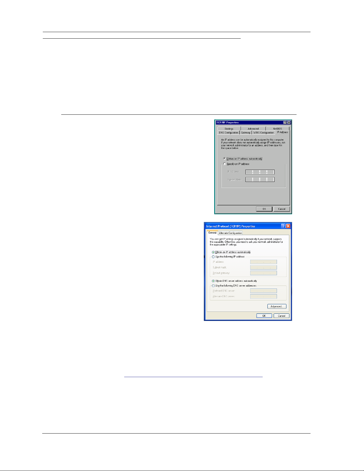
Microsoft Windows:
1. Navigate to the TCP/IP Properties Control Panel.
a. Some Windows versions
follow a path
like this:
b. Some Windows versions
follow a path
like this:
Start menu -> Settings -> Control
Panel -> Network (or Network and
Dial-up Connections -> Local Area
Connection -> Properties) -> TCP/IP
[your_network_card] or Internet Protocol [TCP/IP] -> Properties
Start menu -> Control Panel ->
Network and Internet Connections -> Network Connections ->
Local Area Connection -> Properties -> Internet Protocol [TCP/IP]
-> Properties
Then go to Step 2.
2. Select
3. Select
4. Remove any previously configured gateways, if applicable.
5. Click the OK button. Restart if prompted.
Obtain an IP address automatically
.
Obtain DNS server address automatically
, if available.
Proceed to the next section “Motorola Netopia® Gateway Quickstart” on page 14.
11
Page 12
Administrator’s Handbook
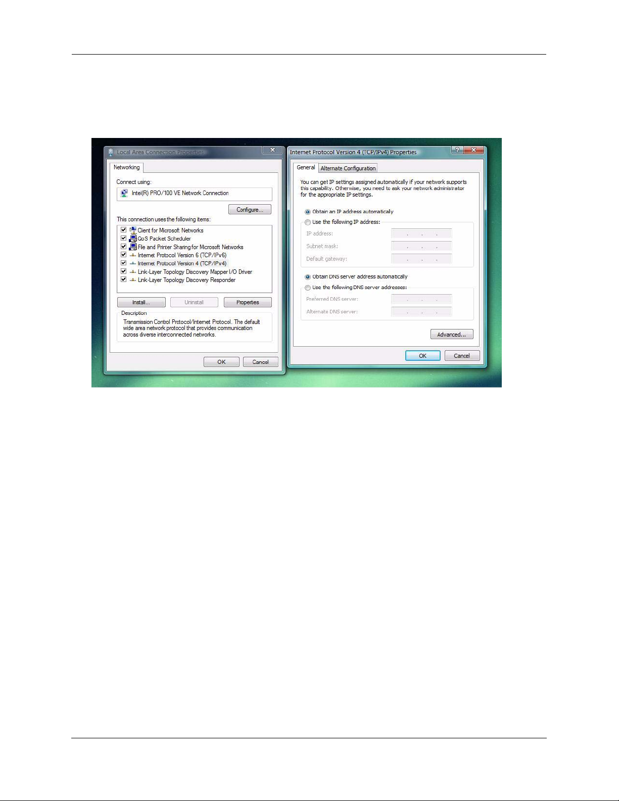
c. Windows Vista is set to obtain an IP address automatically by default. You may not need to configure
it at all.
To check, open the Networking Control Panel and select Internet Protocol Version 4 (TCP/IPv4).
Click the Properties button.
The Internet Protocol Version 4 (TCP/IPv4) Properties window should appear as shown.
If not, select the radio buttons shown above, and click the OK button.
12
Page 13
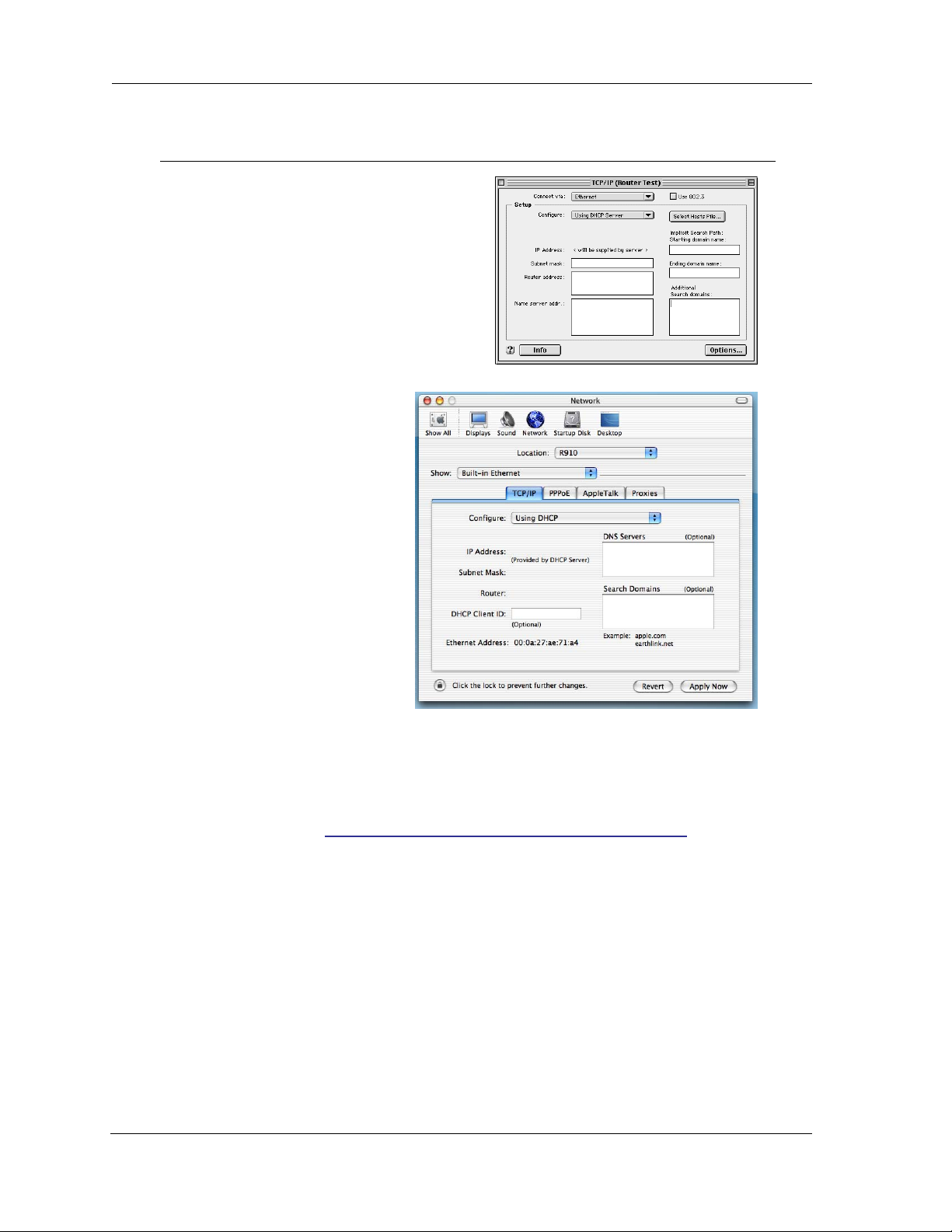
Macintosh MacOS 9.2 and higher or Mac OS X 10.1.5 or higher:
1. Access the TCP/IP or Network control panel.
a. MacOS follows a path
like this:
b. Mac OS X
follows a path
like this:
Apple Menu -> Control Panels -> TCP/IP Control Panel
Apple Menu ->
System Prefer-
->
ences
Network
Then go to Step 2.
2. Select
3. Select
4. Close and Save, if prompted.
Built-in Ethernet
Configure Using DHCP
Proceed to the next section “Motorola Netopia® Gateway Quickstart” on page 14.
13
Page 14
Administrator’s Handbook
Motorola Netopia® Gateway Quickstart
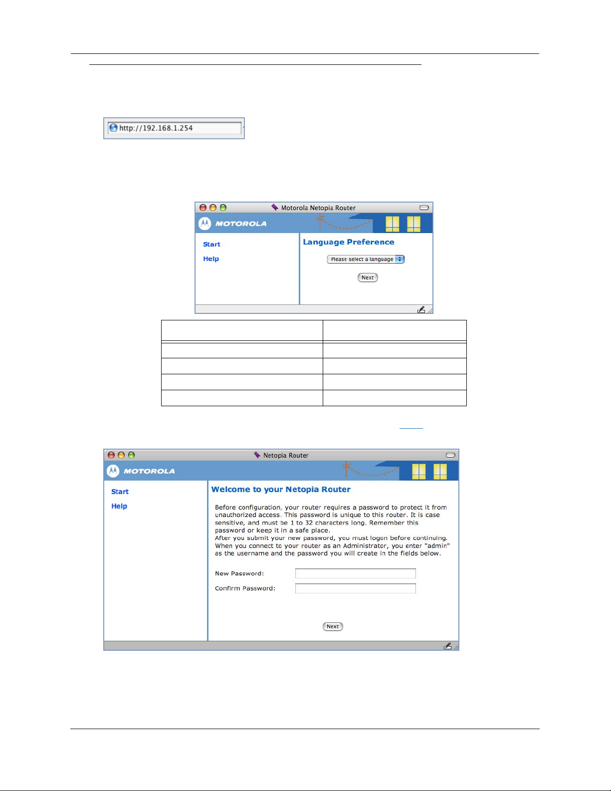
1. Run a Web browser, such as Mozilla Firefox or Microsoft Internet Explorer.
Enter http://192.168.1.254 in the URL Address text box.
Press Return.
(If your ISP’s Configuration Worksheet tells you to use an IP address other than 192.168.1.254 to
log in, enter http://< ip-address>.)
2. The Motorola Netopia
®
Router displays the Language Preference page.
ChoIces in the Americas are: Choices in Europe are:
English English
Español Latinoamericano Français
Portugués do Brasil Deutsch
Italiano
3. Select your language from the pull-down menu and click Next.
The browser displays the Welcome page.
14
For security, you must create and enter an Administrative password for accessing the Motorola Netopia® Gateway.
• The administrative User name is admin.
• The initial Password can be whatever you choose, from one to 32 characters long.
Page 15
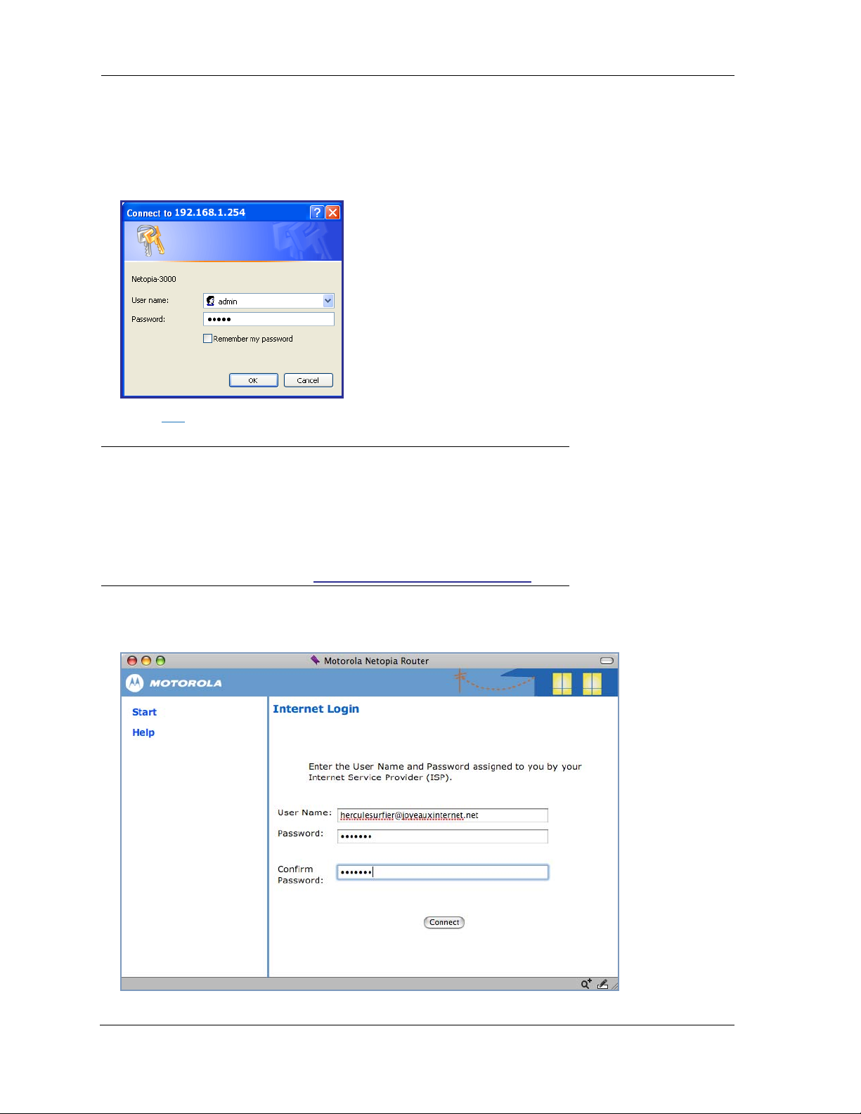
This user name and password are separate from the user name and password you will use to
access the Internet. You may change them later. You will be challenged for this Admin username and
password any time that you attempt to access the Motorola Netopia® Gateway’s configuration
pages.
When you connect to your Gateway as an Administrator, you enter “admin” as the UserName and
the Password you just created.
4. Click OK.
☛ NOTE:
For 3397GP and 7000 Series models, skip the rest of this section.
Congratulations! Your configuration is complete.
You can go directly to “Basic Mode Features” on page 17.
PPPoE Quickstart
The browser displays the Internet Login page.
15
Page 16
Administrator’s Handbook
5. Enter the User Name and Password supplied by your Internet Service Provider.
Click the Connect button.
You will be redirected to an Internet web page to register your new Modem.
Congratulations! Your installation is complete. You can now surf to your favorite Web sites by typing an
URL in your browser’s location box or by selecting one of your favorite Internet bookmarks.
Optional services that you may have contracted with your provider are also available.
If you have any questions or encounter problems with your Motorola Netopia® Gateway, refer to “Basic
Troubleshooting” on page 111, the context-sensitive help in your Gateway’s web pages, or contact your
service provider’s technical support helpdesk.
Answers to many frequently asked product-related questions are also available on-line at:
http://www.motorola.com/us/products.jsp
If you click the Back button on your web browser, the browser displays the Basic Home Page.
16
Page 17

CHAPTER 2 Basic Mode Features
Using the Web-based user interface for the Motorola Netopia® Gateway you can configure, troubleshoot, and monitor the status of your Gateway.
◆ “The Home Page” on page 18
◆ “Links Bar” on page 20
◆ “Firewall” on page 21
◆ “Wireless Protected Setup” on page 24
◆ “Wireless” on page 26
◆ “Gaming” on page 43
◆ “Expert Mode” on page 48
◆ “Troubleshoot” on page 49
◆ “Help” on page 54
17
Page 18
Administrator’s Handbook
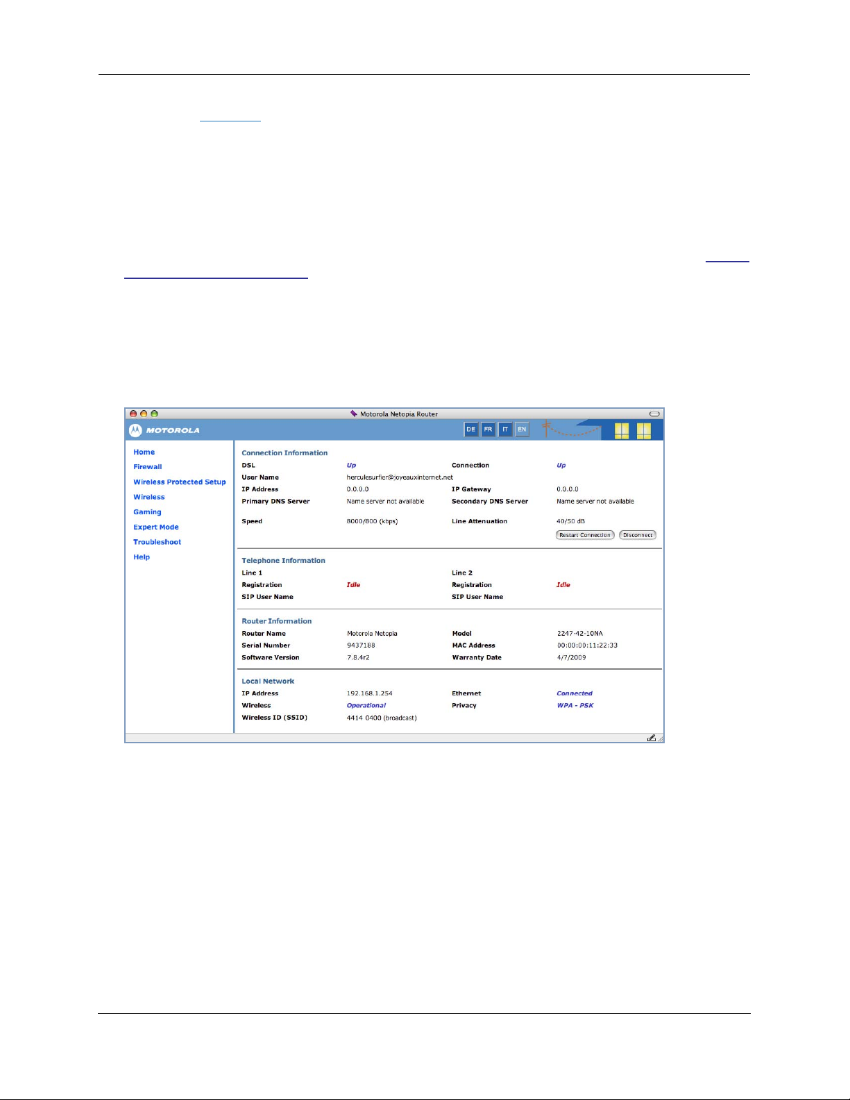
The Home Page
Home Page for a PPPoE Connection
Home Page Information
The Home page displays information about the following categories:
◆ Connection Information
◆ (supported VoIP models only) Telephone Information
◆ Router Information
◆ Local Network
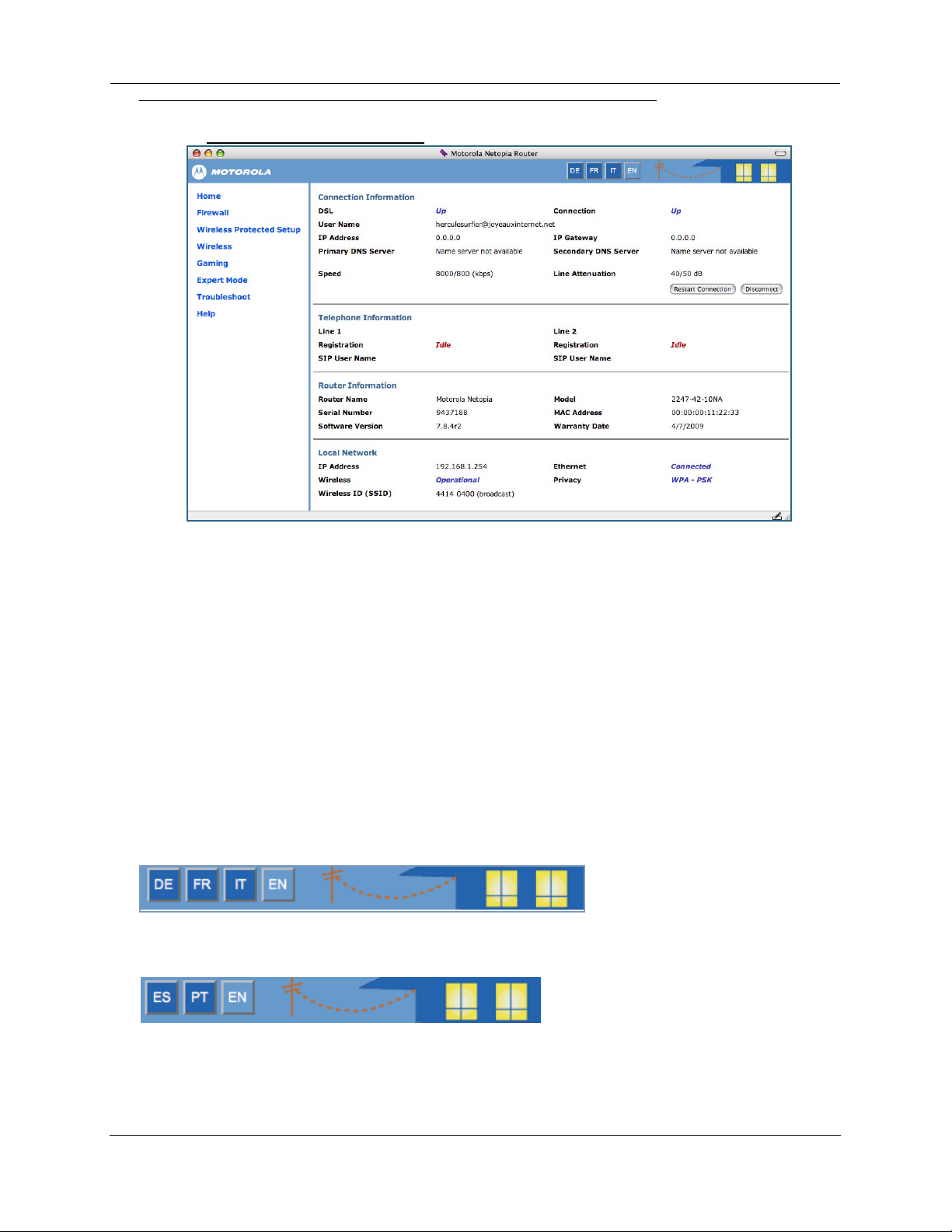
Language Selection Buttons
Language Selection Buttons are located at the top of every page. If you prefer the web UI to be displayed in a different language, you can click one of these buttons, and the pages will display in that language, until you choose a different button.
Supported languages in Europe are German, French, Italian, and English.
Supported languages in the Americas are Latin American Spanish, Brazilian Portuguese, and English.
More Buttons
◆ Restart Connection – For a PPPoE connection, clicking this button will bring down any PPPoE WAN
connection that is up and resend your current PPPoE login credentials and reestablish your Internet
18
Page 19

connection.
For a DHCP connection, clicking this button will release and renew the DHCP lease from your ser vice
provider’s DHCP server, which assigns your local WAN IP address.
◆ Connect – Only displays if you are not connected. For a PPPoE connection, clicking this button will
allow you to attempt to login using a different User ID and Password.
◆ Disconnect – Only for a PPPoE connection, clicking this button will disconnect you from the Internet
until you choose to reestablish your connection manually.
Click the Help link in the left-hand column of links to display a page of explanatory information. Help is
available for every page in the Web interface. See “Help” on page 54.
19
Page 20
Administrator’s Handbook
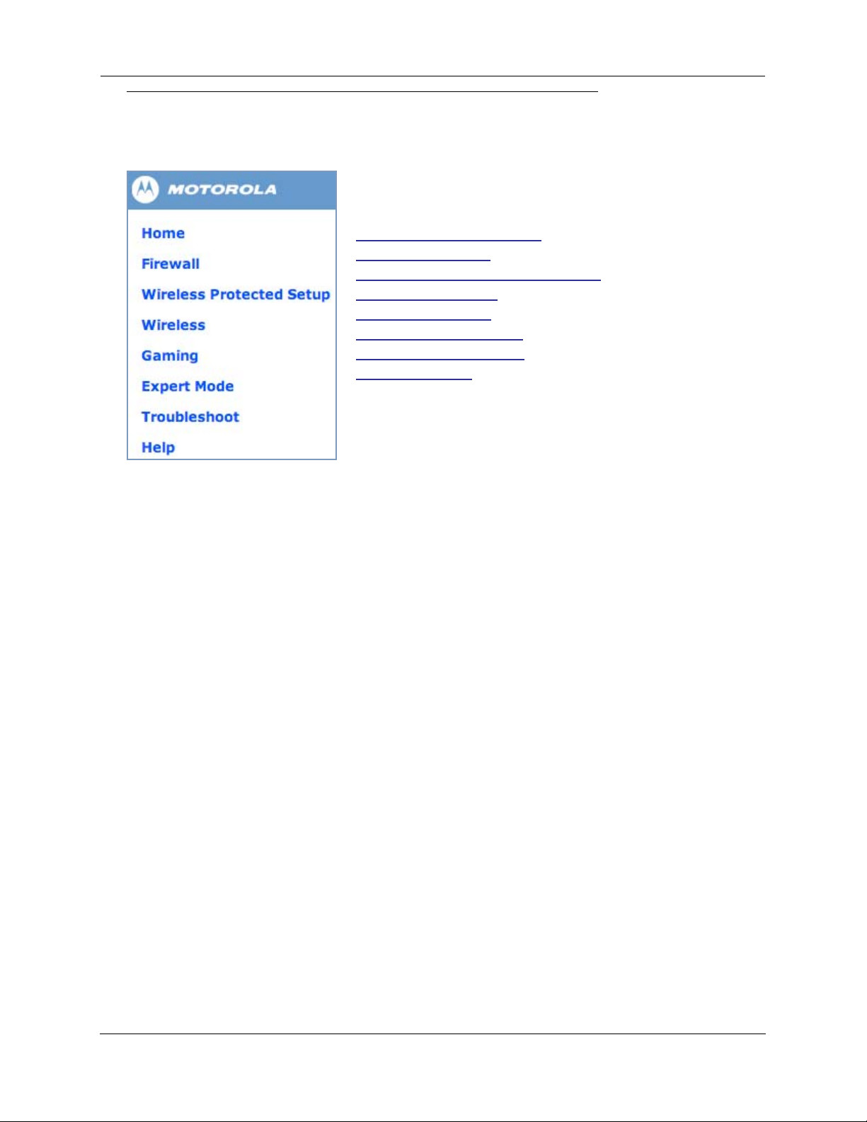
Links Bar
The links in the left-hand column of the Home page access a series of pages to allow you to monitor,
diagnose, and update your Gateway. The following sections give brief descriptions of these pages.
◆“The Home Page” on page 18
◆“Firewall” on page 21
◆“Wireless Protected Setup” on page 24
◆“Wireless” on page 26
◆“Gaming” on page 43
◆“Expert Mode” on page 48
◆“Troubleshoot” on page 49
◆“Help” on page 54
20
Page 21
Firewall
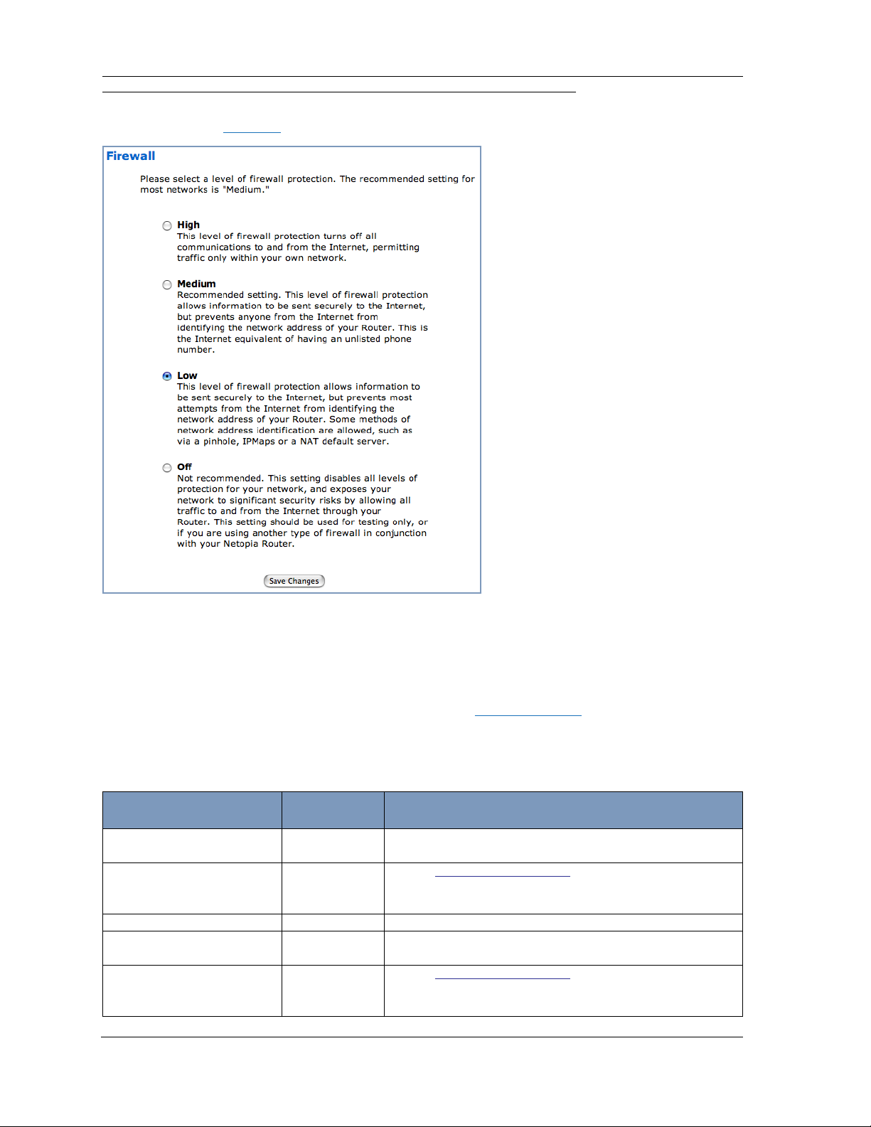
When you click the Firewall link, the Firewall selection page appears.
In addition to the recommended Medium setting, for special circumstances, High and Low levels of
firewall protection are available. You can also turn all firewall protection Off.
Consider your security needs carefully before making any changes here.
If you select a different level of firewall protection, click the Save Changes button.
Firewall Background
The following table gives some tips for Firewall settings:
Application
Typical Internet usage
(browsing, e-mail)
Multi-player online
gaming
Going on vacation High Protects your connection while you’re away.
Finished online use for the
day
Chatting online or using
instant messaging
Select this
Level
Medium
Low Set up “Gaming” on page 43; once defined, services
will be active whenever firewall mode set to Low/Off.
Restore Medium when finished.
High This protects you instead of disconnecting your Gateway
connection.
Off Set up “Gaming” on page 43; once defined, services
will be active whenever Off is set.
Restore Medium when finished.
Other Considerations
21
Page 22

Administrator’s Handbook
As a device on the Internet, a Motorola Netopia® Gateway requires an IP address in order to send or
receive traffic.
The IP traffic sent or received have an associated application port which is dependent on the nature of
the connection request. In the IP protocol standard the following session types are common applications:
◆ ICMP ◆ HTTP ◆ FTP
◆ SNMP ◆ telnet ◆ DHCP
By receiving a response to a scan from a por t or series of por ts (which is the expected behavior according to the IP standard), hackers can identify an existing device and gain a potential opening for access
to an internet-connected device.
To protect LAN users and their network from these types of attacks, the Motorola Netopia® Firewall
offers three levels of increasing protection.
The following tables indicate the state of ports associated with session types, both on the WAN side
and the LAN side of the Gateway.
This table shows how inbound traffic is treated. Inbound means the traffic is coming from the WAN into
the WAN side of the Gateway.
Gateway: WAN Side
Firewall Setting >> Off
Low/Medium*
High
Port Session Type --------------Port State-----------------------
20 ftp data Enabled Disabled Disabled
21 ftp control Enabled Disabled Disabled
23 telnet external Enabled Disabled Disabled
23 telnet Netopia server Enabled Disabled Disabled
80 http external Enabled Disabled Disabled
80 http Netopia server Enabled Disabled Disabled
67 DHCP client Enabled Enabled Disabled
68 DHCP server Not Applicable Not Applicable Not Applicable
161 snmp Enabled Disabled Disabled
ping (ICMP) Enabled Disabled Disabled
22
Page 23

This table shows how outbound traffic is treated. Outbound means the traffic is coming from the LANside computers into the LAN side of the Gateway.
Gateway: LAN Side
Firewall Setting >> Off
Port Session Type --------------Port State-----------------------
20 ftp data Enabled Enabled Disabled
21 ftp control Enabled Enabled Disabled
23 telnet external Enabled Enabled Disabled
23 telnet Netopia server Enabled Enabled Enabled
80 http external Enabled Enabled Disabled
80 http Netopia server Enabled Enabled Enabled
67 DHCP client Not Applicable Not Applicable Not Applicable
68 DHCP server Enabled Enabled Enabled
161 snmp Enabled Enabled Enabled
ping (ICMP) Enabled Enabled WAN - Disabled
Low/Medium*
High
LAN -
Local Address
Only
☛ * NOTES:
• The Low setting allows traffic from IPMaps, pinholes, NAT Default cases; the Medium
setting does not allow such traffic.
• The Gateway’s WAN DHCP client port in Medium mode is enabled. This feature allows
end users to continue using DHCP-served IP addresses from their Service Providers, while
having no identifiable presence on the Internet.
23
Page 24
Administrator’s Handbook
Wireless Protected Setup
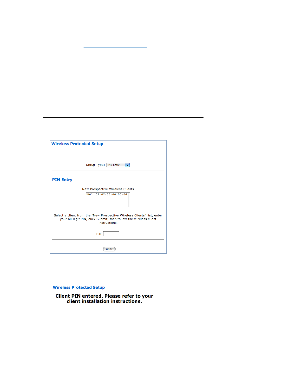
When you click the Wireless Protected Setup link in the left-hand links bar, the Wireless Protected
Setup configuration page appears.
Wireless Protected Setup (WPS) is a not a new security protocol. It is simply an easier way to use
existing protocols to provide greater security for your wireless network connections.
By default, Privacy is set to Wireless Protected Access (WPA-PSK). WPS allows you to automatically generate a new strong WPA key for your Gateway and any client devices on your wireless network.
☛ Note:
Not all client wireless devices support WPS. Refer to their documentation.
This page offers two ways to enable WPS from the Setup Type pull-down menu:
◆ by PIN Entry:
Here, you enter the client's Personal Identification Number (PIN), just as you would for a bank’s ATM
card. Select the MAC address of the client device you want to enable, enter the client's PIN number
(see client WPS setup for details), and click the Submit button.
The Gateway generates a strong WPA key, and displays a completion message.
You must then follow the instructions that came with your WPS-enabled client device to complete the
configuration.
◆ or by using the Gateway’s WPS Push-button.
24
Page 25
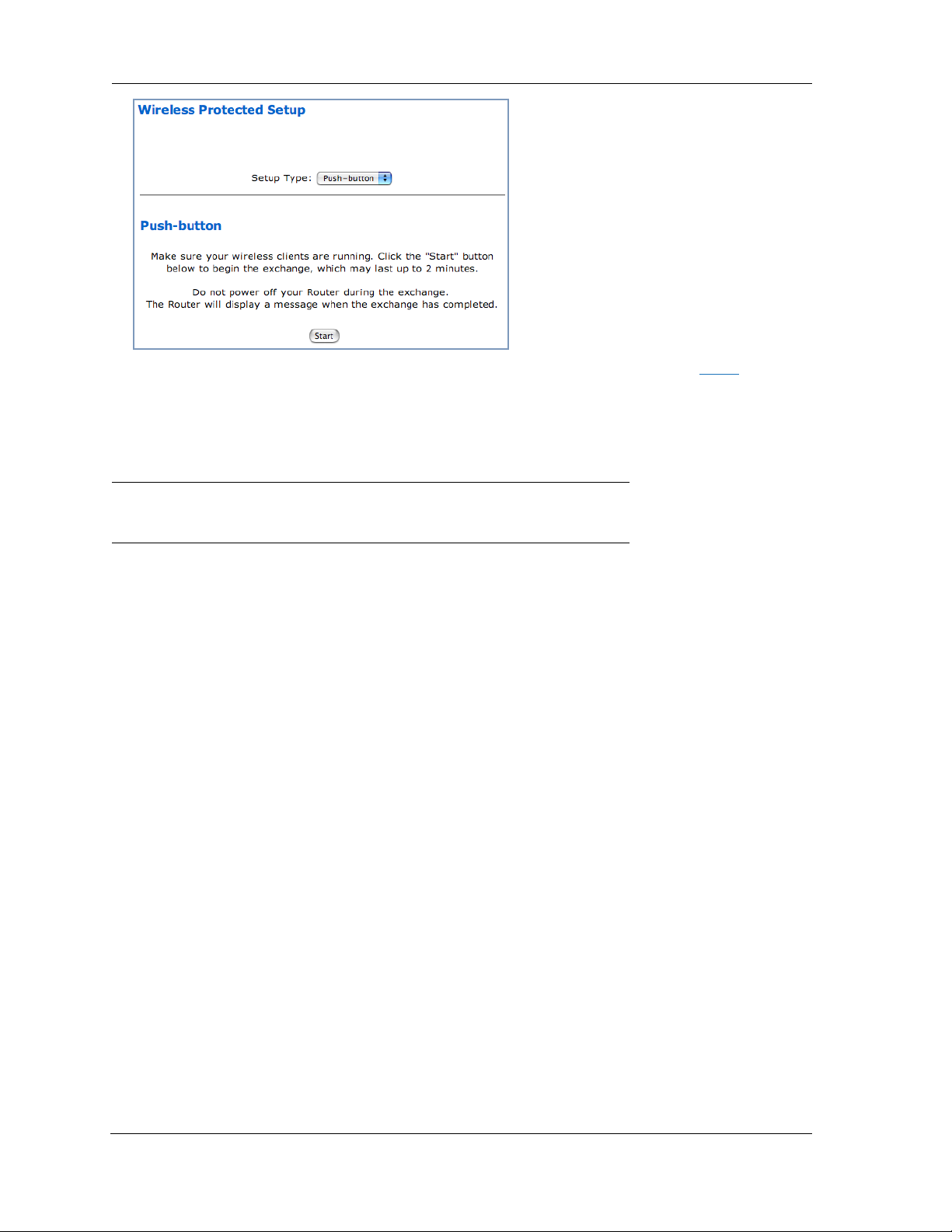
Make sure your wireless client is running and ready for WPS configuration. Click the Start button on
the webpage to begin the exchange, which may last up to two minutes, then continue the WPS pushbutton (PBC) installation on the client.
Do not power off your Router during the exchange.
The Router and the client will display a success message when the exchange has completed.
☛ Be sure to check for the success message on both the Router and the client.
25
Page 26
Administrator’s Handbook
Wireless
(supported models)
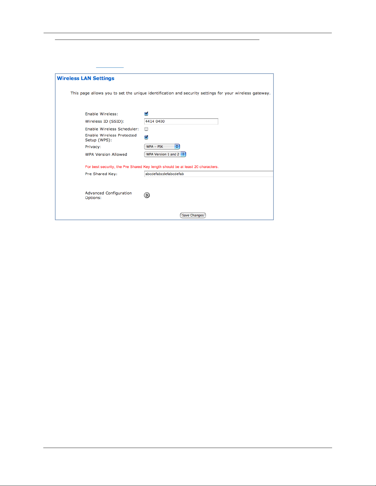
When you click Wireless, the Wireless LAN Settings configuration page appears.
Enable Wireless
The wireless function is automatically enabled by default. If you uncheck the Enable Wireless checkbox, the Wireless Options are disabled, and the Gateway will not provide or broadcast its wireless LAN
services.
Wireless ID (SSID)
The Wireless ID is preset to a number unique to your unit. You can either leave it as is, or change it by
entering a freeform name of up to 32 characters, for example “Hercule’s Wireless LAN”. On client PCs’
software, this might also be called the Network Name. The Wireless ID is used to identify this particular
wireless LAN. Depending on their operating system or client wireless card, users must either:
◆ select from a list of available wireless LANs that appear in a scanned list on their client
◆ or enter this name on their clients in order to join this wireless LAN.
26
Page 27
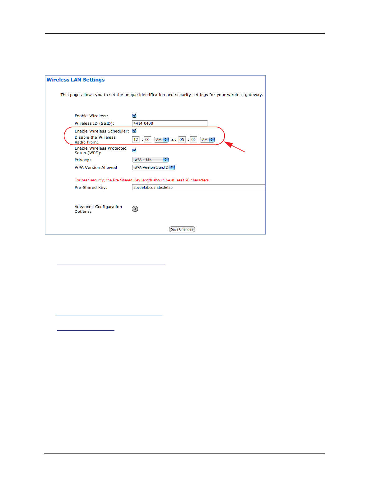
Enable Wireless Scheduler
If you check the Enable Wireless Scheduler checkbox, the screen expands to allow you to set times
of day when the wireless radio will turn off and on. This makes it possible to control your wireless LAN’s
hours of operation automatically.
Enable Wireless Protected Setup (WPS)
See “Wireless Protected Setup” on page 24.
Privacy
By default, Privacy is set to
Other privacy options, as well as other advanced wireless options are available. To access them, click
the Advanced Configuration Options button.
See “Privacy” on page 30 for more information.
WPA-PSK
with a Wireless Protected Access Pre-Shared key.
27
Page 28

Administrator’s Handbook
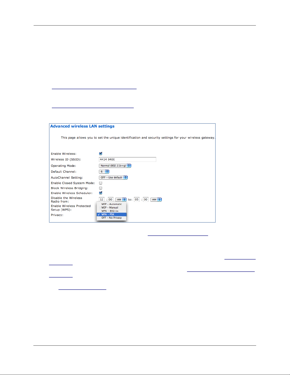
Advanced Configuration Options (optional)
When you click the Advanced Configuration Options button, the Advanced wireless LAN settings screen appears. This screen varies its options depending on which form of wireless Privacy you
have selected.
Operating Mode
The pull-down menu allows you to select and lock the Gateway into the wireless transmission mode you
want. For compatibility with clients using 802.11b (up to 11 Mbps transmission) and 802.11g (up to
20+ Mbps), select Normal (802.11b + g). To limit your wireless LAN to one mode or the other, select
802.11b Only, or 802.11g Only.
☛ NOTE:
If you choose to limit the operating mode to 802.11b or 802.11g only, clients using the
mode you excluded will not be able to connect.
Default Channel
(1 through 11, for North America) on which the network will broadcast. This is a frequency range within
the 2.4Ghz band. Channel selection depends on government regulated radio frequencies that var y from
region to region. The widest range available is from 1 to 14. Europe, France, Spain and Japan dif fer.
Channel selection can have a significant impact on performance, depending on other wireless activity
28
Page 29

close to this Router. Channel selection is not necessary at the client computers; the clients will scan
the available channels seeking access points using the same SSID as the client.
AutoChannel Setting
For 802.11G models, AutoChannel is a feature that allows the Motorola Netopia® Gateway to determine the best channel to broadcast automatically.
Three settings are available from the pull-down menu: Off-Use default, At Startup, and Continuous.
◆ Off-Use default: the Motorola Netopia® Gateway will use the configured default channel selected
from the previous pull-down menu.
◆ At Startup – the default setting – causes the Motorola Netopia® Gateway at star tup to briefly initial-
ize on the default channel, then perform a full two- to three-second scan, and switch to the best
channel it can find, remaining on that channel until the next reboot.
◆ Continuous performs the at-startup scan, and will continuously monitor the current channel for any
other Access Point beacons. If an Access Point beacon is detected on the same channel, the Motorola Netopia® Gateway will initiate a three- to four-minute scan of the channels, locate a better one,
and switch. Once it has switched, it will remain on this channel for at least 30 minutes before
switching again if another Access Point is detected.
Enable Closed System Mode
If enabled, Closed System Mode hides the wireless network from the scanning features of wireless client computers. Unless both the wireless clients and the Router share the same Wireless ID in Closed
System mode, the Router’s wireless LAN will not appear as an available network when scanned for by
wireless-enabled computers. Members of the Closed System WLAN must log onto the Router’s wireless
network with the identical SSID as that configured in the router.
Closed System mode is an ideal way to increase wireless security and to prevent casual detection by
unwanted neighbors, office users, or malicious users such as hackers.
If you do not enable Closed System Mode, it is more convenient, but potentially less secure, for clients
to access your WLAN by scanning available access points. You must decide based on your own network
requirements.
About Closed System Mode and Wireless Encryption
Enabling Closed System Mode on your wireless Router provides another level of security, since your
wireless LAN will no longer appear as an available access point to client PCs that are casually scanning
for one.
Your own wireless network clients, however, must log into the wireless LAN by using the exact SSID of
the Motorola Netopia
In addition, if you have enabled WEP or WPA encryption on the Motorola Netopia® Router, your network
clients must also have WEP or WPA encryption enabled, and must have the same WEP or WPA encr yp-
tion key as the Motorola Netopia® Router.
Once the Motorola Netopia® Gateway is located by a client computer, by setting the client to a matching
SSID, the client can connect immediately if WEP or WPA is not enabled. If WEP or WPA is enabled then
the client must also have WEP or WPA enabled and a matching WEP or WPA key.
®
Router.
29
Page 30
Administrator’s Handbook
Wireless client cards from dif ferent manufacturers and dif ferent operating systems accomplish connecting to a wireless LAN and enabling WEP or WPA in a variety of ways. Consult the documentation for
your particular wireless card and/or operating system.
Block Wireless Bridging
Check the checkbox to block wireless clients from communicating with other wireless clients on the
LAN side of the Gateway.
Enable Wireless Scheduler
See “Enable Wireless Scheduler” on page 27.
Enable Wireless Protected Setup (WPS)
See “Wireless Protected Setup” on page 24.
Privacy
◆ WEP - Automatic: provides an easy way to generate WEP (Wired Equivalent Privacy) keys for
encryption of your wireless network traffic. See “WEP-Automatic” on page 35.
◆ WEP - Manual: WEP Security is a Privacy option that is based on encryption between the Router
and any PCs (“clients”) you have with wireless cards. If you are not using WPA-PSK Privacy, you can
use WEP encryption instead. For this encryption to work, both your Router and each client must
share the same Wireless ID, and both must be using the same encr yption keys. See “WEP-Manual”
on page 33.
◆ WPA-802.1x provides RADIUS ser ver authentication suppor t. See “
on page 30 below.
◆ WPA-PSK provides Wireless Protected Access, the most secure option for your wireless network.
WPA-PSK” on page 32. This mechanism provides the best data protection and access control.
See “
Be sure that your Wi-Fi client adapter supports this option. Not all Wi-Fi clients support WPA-PSK.
◆ OFF - No Privacy: This mode disables privacy on your network, allowing any wireless users to con-
nect to your wireless LAN. Use this option if you are using alternative security measures such as
VPN tunnels, or if your network is for public use.
RADIUS Server authentication
RADIUS servers allow external authentication of users by means of a remote authentication database.
The remote authentication database is maintained by a Remote Authentication Dial-In User Service
RADIUS Server authentication”
30
Page 31

(RADIUS) server. In conjunction with Wireless User Authentication, you can use a RADIUS server database to authenticate users seeking access to the wireless services, as well as the authorized user list
maintained locally within the Gateway.
If you select WPA-802.1x, the screen expands.
Click the Configure RADIUS Server button.
The Configure RADIUS Server screen appears.
Enter your RADIUS Server information in the
appropriate fields:
◆RADIUS Server Addr/Name: The default
RADIUS server name or IP address that you
want to use.
◆RADIUS Server Secret: The RADIUS secret
key used by this server. The shared secret
should have the same characteristics as a normal password.
◆ Alt RADIUS Server Addr/Name: An alternate RADIUS server name or IP address, if available.
◆ Alt RADIUS Server Secret: The RADIUS secret key used by this alternate ser ver. The shared
secret should have the same characteristics as a normal password.
◆ RADIUS Server Port: The port on which the RADIUS server is listening, typically, the default 1812.
Click the Save Changes button.
31
Page 32

Administrator’s Handbook
WPA-PSK
One of the easiest ways to enable Privacy on your Wireless network is by selecting
WPA-PSK (Wi-Fi Protected Access) from the pull-down menu.
The screen expands to allow you to enter a Pre Shared Key. The key can be between 8 and 63 charac-
ters, but for best security it should be at least 20 characters. When you have entered your key, click the
Save Changes button.
32
Page 33

WEP-Manual
Alternatively, you can enable WEP (Wired Equivalent Privacy) encryption by selecting
WEP-Manual from the Privacy pull-down menu.
You can provide a level of data security by enabling WEP (Wired Equivalent Privacy) for encryption of network data. You can enable 40-, 128-, or 256-bit WEP Encr yption (depending on the capability of your client wireless card) for IP traffic on your LAN.
WEP - Manual allows you to enter your own encryption keys manually. This is a dif ficult process, but
only needs to be done once. Avoid the temptation to enter all the same characters.
Encryption Key Size #1 – #4: Selects the length of each encryption key. The longer the key, the stronger the encryption and the more difficult it is to break the encryption.
Encryption Key #1 – #4: The encryption keys. You enter keys using hexadecimal digits. For 40/64bit
encryption, you need ten digits; 26 digits for 128bit, and 58 digits for 256bit WEP. Hexadecimal characters are 0 – 9, and a – f.
33
Page 34

Administrator’s Handbook
Examples:
◆ 40bit: 02468ACE02
◆ 128bit: 0123456789ABCDEF0123456789
◆ 256bit: 592CA140F0A238B0C61AE162F592CA140F0A238B0C61AE162F21A09C
Use WEP encryption key (1 – 4) #: Specifies which key the Gateway will use to encrypt transmitted
traffic. The default is key #1.
Click the click Save Changes button.
Any WEP-enabled client must have an identical key of the same length as the Router, in order to successfully receive and decrypt the traffic. Similarly, the client also has a ‘default’ key that it uses to
encrypt its transmissions. In order for the Router to receive the client’s data, it must likewise have the
identical key of the same length.
34
Page 35

WEP-Automatic
Alternatively, you can enable WEP (Wired Equivalent Privacy) encryption by selecting
WEP-Automatic from the Privacy pull-down menu.
You can provide a level of data security by enabling WEP (Wired Equivalent Privacy) for encryption of network data. You can enable 40-, 128-, or 256-bit WEP Encr yption (depending on the capability of your client wireless card) for IP traffic on your LAN.
Enter a Passphrase. The number of characters to use is shown in the pull-down menu. Click the
Changes
Any WEP-enabled client must have an identical key of the same length as the Router, in order to successfully receive and decrypt the traffic. Similarly, the client also has a ‘default’ key that it uses to
encrypt its transmissions. In order for the Router to receive the client’s data, it must likewise have the
identical key of the same length.
button. This will generate an encryption key automatically.
Save
35
Page 36

Administrator’s Handbook
Enable Multiple Wireless IDs
This feature allows you to add additional network identifiers (SSIDs or Network Names) for your wireless
network. To enable Multiple Wireless IDs, click the button.
The Enable Multiple Wireless IDs screen appears to allow you to add up to three additional Wireless
IDs.
When the Multiple Wireless SSIDs screen appears, check the Enable SSID checkbox for each SSID
you want to enable.
The screen expands to allow you to name each additional Wireless ID, and specify a Privacy mode for
each one.
◆ You can enable or disable Closed System Mode for each SSID by checking or unchecking the
checkbox. See “Enable Closed System Mode” on page 29 for more information.
◆ Privacy modes available from the pull-down menu for the multiple SSIDs are: WPA-PSK, WPA-
802.1x, or Off-No Privacy. WEP-Automatic or WEP-Manual are also available if not already con-
figured on the primary SSID or a previous multiple SSID.
36
Page 37

◆ You also have the choice of applying WPA Version 1 and 2, WPA Version 1 Only, or WPA Version
2 Only from the pull-down menu. These can be applied to each SSID individually.
◆ If you choose WPA-802.1x privacy, the Configure RADIUS Ser ver option appears, to allow you to
specify your RADIUS server information. See “RADIUS Server authentication” on page 30.
◆ You can now choose to Limit Wireless Access by MAC Address. This allows you to restrict individual
clients’ access to each SSID separately. Click the Limit Wireless Access by MAC Address but-
ton.
The MAC Authorization for that SSID screen appears.
Select Enabled from the pull-down menu. The screen expands to allow you to add authorized clients’ MAC addresses.
37
Page 38

Administrator’s Handbook
You do this in the same manner as you do to authorize MAC addresses for the primar y SSID. See
“Wireless MAC Authorization (optional)” on page 41.
Click the Save Changes button. The Gateway will prompt you to restart it.
Click the Yes button, and the Gateway will restart with your new settings.
☛ NOTES:
The Gateway supports up to 4 different SSIDs:
• One SSID is broadcast by default and has wireless bridging enabled by
default.
• These network IDs can now be configured separately in terms of MAC
Address filtering.
• You can configure privacy on one SSID and disable it on another SSID.
38
Page 39

WiFi Multimedia
WiFi Multimedia is an advanced feature that allows you to prioritize various types of data travelling over
the wireless network. Certain types of data that are sensitive to delays, such as voice or video, must be
prioritized ahead of other, less delay-sensitive types, such as email.
WiFi Multimedia currently implements wireless Quality of Ser vice (QoS) by transmitting data depending
on Diffserv priority settings. These priorities are mapped into four Access Categories (AC), in increasing
order of priority:
◆ Background (BK),
◆ Best Effort (BE),
◆ Video (VI), and
◆ Voice (VO).
It requires WiFi Multimedia (WMM)-capable clients, usually a separate feature enabled at the client network settings, and client PC software that makes use of Differentiated Services (Diffser v). Refer to
your operating system instructions for enabling Diffserv QoS.
When you click the
To enable the WiFi Multimedia custom settings, select Diffserv from the pull-down menu.
WiFi Multimedia button the WiFi Multimedia page appears.
39
Page 40

Administrator’s Handbook
The screen expands.
Router EDCA Parameters (Enhanced Distributed Channel Access) govern wireless data from your
Gateway to the client; Client EDCA Parameters govern wireless data from the client to your Gateway.
☛ NOTE:
It is not recommended that you modify these settings without direct knowledge or instructions to do so. Modifying these settings inappropriately could seriously degrade network
performance.
◆ AIFs: (Arbitration Interframe Spacing) the wait time in milliseconds for data frames.
◆ cwMin: (Minimum Contention Window) upper limit in milliseconds of the range for determining initial
random backoff. The value you choose must be lower than cwMax.
◆ cwMax: (Maximum Contention Window) upper limit in milliseconds of the range of determining final
random backoff. The value you choose must be higher than cwMin.
◆ TXOP Limit: Time interval in microseconds that clients may initiate transmissions.
(When Operating Mode is B-only, default values are used and this field is not configurable.)
Click the Save Changes button.
40
Page 41

Wireless MAC Authorization (optional)
MAC Authorization allows you to specify which client PCs are allowed to join the wireless LAN by unique
hardware (MAC) address. To enable this feature, click the Limit Wireless Access by MAC
Address button. The MAC Authorization screen appears.
Select Enabled from the pull-down menu.
The screen expands to permit you to add MAC addresses.
Click the Add button.
Once it is enabled, only entered MAC addresses that have been set to
wireless LAN. All unlisted addresses will be blocked, in addition to the listed addresses with Allow disabled.
Allow
will be accepted onto the
41
Page 42

Administrator’s Handbook
Click the Submit button.
When you are finished adding MAC addresses click the Save Changes button. You will be returned to
the Advanced wireless LAN settings page. You can Add, Edit, or Delete any of your entries later by
returning to this page.
42
Page 43

Gaming
When you click Gaming, the NAT (Games and Other Services) page appears.
NAT (Games and Other Services) allows you to host internet applications when NAT is enabled. You
can host different games and software on different PCs.
From the Service Name pull-down menu, you can select any of a large number of predefined games
and software. (See “List of Supported Games and Software” on page 44.)
1. Once you choose a software service or game, click Enable.
The Enable Service screen appears.
Host Device specifies the machine on which the selected software is hosted.
2. Select a PC to host the software from the Select Host Device pull-down menu and
click
Enable.
Each time you enable a software service or game your entry will be added to the list of Service
Names displayed on the NAT Configuration page.
To remove a game or software from the hosted list, choose the game or software you want to remove
and click the Disab
le button.
43
Page 44

Administrator’s Handbook
List of Supported Games and Software
Act of War - Direct Action Age of Empires II Age of Empires, v.1.0
Age of Empires: The Rise of
Rome, v.1.0
AIM Talk America's Army Apache
Asheron's Call Azureus Baldur's Gate I and II
Battlefield 1942 Battlefield Communicator Battlefield Vietnam
BitTornado BitTorrent Black and White
Blazing Angels Online Brothers in Arms - Earned in
Buddy Phone Calista IP Phone Call of Duty
CART Precision Racing, v 1.0 Citrix Metaframe/ICA Client Close Combat for Windows 1.0
Close Combat III: The Russian
Front, v 1.0
Combat Flight Sim: WWII
Europe Series, v 1.0
Delta Force (Client and Server) Delta Force 2 Delta Force Black Hawk Down
Diablo II Server Dialpad DNS Server
Doom 3 Dues Ex Dune 2000
Age of Mythology Age of Wonders
Brothers in Arms Online
Blood
Close Combat: A Bridge Too
Far, v 2.0
Counter Strike Dark Reign
Combat Flight Sim 2: WWII
Pacific Thr, v 1.0
eDonkey Empire Earth Empire Earth 2
eMule eMule Plus F-16, Mig 29
F-22, Lightning 3 Far Cry Fighter Ace II
FTP GNUtella Grand Theft Auto 2 Multiplayer
H.323 compliant (Netmeeting,
CUSeeME)
Half Life 2 Steam Server Half Life Steam Half Life Steam Server
Halo Hellbender for Windows, v 1.0 Heretic II
Hexen II Hotline Server HTTP
HTTPS ICQ 2001b ICQ Old
IMAP Client IMAP Client v.3 Internet Phone
IPSec IKE iTunes Jedi Knight II: Jedi Outcast
Kali KazaA Lime Wire
Links LS 2000 Lord of the Rings Online Mech Warrior 3
MechWarrior 4: Vengeance Medal of Honor Allied Assault Microsoft Flight Simulator
Microsoft Flight Simulator 98 Microsoft Golf 1998 Edition, v
Half Life Half Life 2 Steam
2000
Microsoft Golf 1999 Edition
1.0
44
Page 45

Microsoft Golf 2001 Edition Midtown Madness, v 1.0 mIRC Auth-IdentD
mIRC Chat mIRC DCC - IRC DCC Monster Truck Madness 2, v
2.0
Monster Truck Madness, v 1.0 Motocross Madness 2, v 2.0 Motocross Madness, v 1.0
MSN Game Zone MSN Game Zone DX MSN Messenger
Need for Speed 3, Hot Pursuit Need for Speed, Porsche Net2Phone
NNTP Operation FlashPoint Outlaws
pcAnywhere (incoming) PlayStation Network POP-3
PPTP Quake 2 Quake 3
Quake 4 Rainbow Six RealAudio
Return to Castle Wolfenstein Roger Wilco Rogue Spear
ShoutCast Server SMTP SNMP
Soldier of Fortune SSH server StarCraft
Starfleet Command StarLancer, v 1.0 TeamSpeak
Telnet TFTP Tiberian Sun: Command and
Conquer
Timbuktu Total Annihilation Ultima Online
Unreal Tournament Server Urban Assault, v 1.0 VNC, Virtual Network Comput-
ing
Warlords Battlecry Warrock Westwood Online, Command
and Conquer
Win2000 Terminal Ser ver Wolfenstein Enemy Territory World of Warcraft
X-Lite XBox 360 Media Center XBox Live 360
Yahoo Messenger Chat Yahoo Messenger Phone ZNES
Define Custom Service
To configure a Custom Service, choose whether to use Port Forwarding or Trigger Ports.
◆ Port Forwarding forwards a range of WAN por ts to an IP address on the LAN.
◆ Trigger Ports forwards a range of ports to an IP address on the LAN only after specific outbound
traffic “triggers” the feature.
Click the Next button.
45
Page 46

Administrator’s Handbook
If you chose Port Forwarding, the Port Range entry screen appears.
Port Forwarding forwards a range of WAN ports to an IP address on the LAN. Enter the following information:
◆ Service Name: A unique identifier for the Custom Service.
◆ Global Port Range: Range of ports on which incoming traffic will be received.
◆ Base Host Port: The port number at the star t of the por t range your Gateway should use when for-
warding traffic of the specified type(s) to the internal IP address.
◆ Protocol: Protocol type of Internet traffic, TCP or UDP.
Click the Next button.
If you chose Trigger Ports, the Trigger Ports entry screen appears.
Trigger Ports for wards a range of por ts to an IP address on the LAN only after specific outbound traf fic
“triggers” the feature. Enter the following information:
◆ Service Name: A unique identifier for the Custom Service.
◆ Global Port Range: Range of ports on which incoming traffic will be received.
◆ Local Trigger Port: Port number of the type of outbound traf fic that needs to happen (will be the
trigger) to then allow the configured ports for inbound traffic.
Example: Set the trigger port to 21 and configure a range of 25 – 110. You would need to do an outbound ftp before you were able to do an inbound smtp.
Click the Next button.
Static NAT
This feature allows you to:
46
Page 47

◆ Direct your Gateway to forward all externally initiated IP traf fic (TCP and UDP protocols only) to a
default host on the LAN.
◆ Enable it for certain situations:
– Where you cannot anticipate what port number or packet protocol an in-bound application might
use. For example, some network games select arbitrary port numbers when a connection is opened.
– When you want all unsolicited traffic to go to a specific LAN host.
This feature allows you to direct unsolicited or non-specific traffic to a designated LAN station. With NAT
“On” in the Gateway, these packets normally would be discarded.
For instance, this could be application traffic where you don’t know (in advance) the port or protocol
that will be used. Some game applications fit this profile.
From the pull-down menu, select the address of the PC that you want to be your default NAT destination.
Click the Next button, and your choice will be so designated.
47
Page 48

Administrator’s Handbook
Expert Mode
Expert Mode allows you to configure a wide variety of specific Gateway and networking settings. Expert
Mode is for advanced users and system administrators, and most users will not need to modify these
settings. If you need to enter Expert Mode, and click the Expert Mode link, you will be challenged to
confirm your choice.
Consult with your Internet Service Provider or your system administrator before attempting to modify
any settings in the Expert Mode.
When you click Yes, enter expert mode, the Expert Mode Home page appears.
For information go to “Expert Mode” on page 55.
48
Page 49

Troubleshoot
When you click the Troubleshoot link, the Links Bar expands to
offer two troubleshooting sub-headings:
◆“Diagnostics” on page 50
◆“Statistics” on page 51
49
Page 50

Administrator’s Handbook
Diagnostics
This automated multi-layer test examines the functionality of the Gateway from the physical connections to the data traffic being sent by users through the Gateway.
You enter a web address URL or an IP address in the Web Address field and click the Test button.
Results will be displayed in the Progress Window as they are generated.
This sequence of tests takes approximately one minute to generate results. Please wait for the test to
run to completion.
Each test generates one of the following result codes:
Result Meaning
* PASS: The test was successful.
* FAIL: The test was unsuccessful.
* SKIPPED: The test was skipped because a test on which it depended failed.
* PENDING: The test timed out without producing a result. Try running Diagnostics again.
* WARNING: The test was unsuccessful. The Service Provider equipment your Gateway
connects to may not support this test.
50
Page 51

Statistics
When you click Statistics in the left hand column of links, the links bar expands to display six statistical sub-headings:
◆“DSL” on page 51
◆“ATM” on page 52
◆“Ethernet” on page 52
◆“IP” on page 52
◆“LAN” on page 52
◆“Wireless” on page 53
◆“Logs” on page 53
These screens will vary depending on your Gateway’s model and traffic activity.
☛ Note:
Available Statistics links vary by platform.
DSL
When you click DSL, the DSL Statistics page appears.
The DSL Statistics page displays information about the Gateway's WAN connection to the Internet.
◆ Line State: May be Up (connected) or Down (disconnected).
◆ Modulation: Method of regulating the DSL signal. DMT (Discrete MultiTone) allows connections to
work better when certain radio transmitters are present.
◆ Data Path: Type of path used by the device's processor.
Downstream and Upstream statistics
◆ Max Allowed Speed (kbps): Your maximum speeds for downloading (receiving) and uploading
(sending) data on the DSL line, in kilobits per second.
◆ SN Margin (db): Signal to noise margin, in decibels. Reflects the amount of unwanted “noise” on
the DSL line.
◆ Line Attenuation: Amount of reduction in signal strength on the DSL line, in decibels.
◆ CRC Errors: Number of times data packets have had to be resent due to errors in transmission or
reception.
51
Page 52

Administrator’s Handbook
ATM
When you click ATM, the ATM Statistics page appears.
The ATM Statistics page:
◆ displays your Gateway's unique hardware (MAC) address.
◆ displays detailed statistics about your WAN data traffic, upstream and downstream.
This information is useful for troubleshooting and when seeking technical suppor t.
Ethernet
When you click Ethernet, the Ethernet Statistics page appears.
The Ethernet Statistics page:
◆ displays your Gateway's unique hardware (MAC) address.
◆ displays detailed statistics about your LAN data traffic, upstream and downstream.
IP
When you click IP, the IP Statistics page appears. The IP Statistics page displays the IP inter faces and
routing table information about your network.
General
◆ IP WAN Address: The public IP address of your Gateway, whether dynamically or statically
assigned.
◆ IP Gateway: Your ISP's gateway Gateway IP address
◆ Primary DNS: The IP address of the Primary Domain Name Server
◆ Primary DNS name: The name of the Primary Domain Name Server
◆ Secondary DNS: The IP address of the backup Domain Name Server (if any)
◆ Secondary DNS name: The name of the backup Domain Name Server
IP interfaces
◆ Address: Your Gateway's IP address as seen from your internal network (LAN), and from the public
Internet (WAN)
◆ Netmask: The subnet mask for the respective IP interfaces (LAN and WAN)
◆ Name: The name of each IP interface (example:Eth0, WAN2)
Network Routing Table and Host Routing Table
The Routing tables display all of the IP routes currently known to your Gateway
LAN
When you click LAN, the LAN Statistics page appears.
The LAN Statistics page displays detailed information about your LAN IP configuration and names and
IP addresses of devices on your LAN.
◆ Router IP Address: The IP address of your Gateway as seen from the LAN
◆ Subnet Mask: Subnet mask of your LAN
◆ DHCP Start Address: First IP address in the range being served to your LAN by the Gateway's
DHCP server
52
Page 53

◆ DHCP End Address: Last IP address in the range being served to your LAN by the Gateway's DHCP
server
◆ DHCP Server Status: May be On or Off
◆ DNS Server: The IP address of the default DNS server
Devices on LAN
Displays the IP Address, MAC (hardware) Address, and network Name for each device on your LAN connected to the Gateway.
Wireless
When you click Wireless, the Wireless Statistics page appears.
The Wireless Statistics page:
◆ displays your Router's unique hardware Wireless (MAC) address.
◆ displays detailed statistics about your Wireless LAN data traffic, upstream and downstream.
Logs
When you click Logs, the Logs page appears.
Select a log from the pull-down menu:
◆ All: Displays the entire system log.
◆ Connection: Displays events logged for the WAN connection.
◆ System: Displays events logged for the Gateway system configuration.
The current status of the Gateway is displayed for all logs.
◆ You can clear all log entries by clicking the Clear All Logs button.
◆ You can save logs to a text (.TXT) file by clicking the Save to File button. This will create a text file
that you can save to your hard drive. The file can be opened with your favorite text editor.
☛ Note:
Some browsers, such as Internet Explorer for Windows XP, require that you specify the
Motorola Netopia® Gateway’s URL as a “Trusted site” in “Internet Options: Security”. This
is necessary to allow the “download” of the log text file to the PC.
53
Page 54

Administrator’s Handbook
Help
Click the Help link in the left-hand column of links to display a page of explanatory information. Help is
available for every page in the Web interface.
Here is an example:
54
Page 55

CHAPTER 3 Expert Mode
Using the Expert Mode Web-based user interface for the Motorola Netopia® Gateway you can configure,
troubleshoot, and monitor the status of your Gateway.
This section covers the following topics:
◆ “Home Page - Expert Mode” on page 56
◆ “Help” on page 58
◆ “Links Bar” on page 59
◆ “Configure” on page 60
◆ “Statistics” on page 102
◆ “Diagnostics” on page 105
◆ “Remote Access” on page 106
◆ “Update Router” on page 107
◆ “Reset Router” on page 108
◆ “Restart Router” on page 109
◆ “Basic Mode” on page 110
55
Page 56

Administrator’s Handbook
Home Page - Expert Mode
The Home Page is the summary page for your Motorola Netopia® Gateway. The toolbar on the left side
provides links to controlling, configuring, and monitoring pages. Critical configuration and operational
status is displayed in the center section.
When you click Yes, enter expert mode, the Expert Mode Home page appears.
Home Page for a PPPoE Connection
Home Page Information
The Home page displays information about the following categories:
◆ Connection Information
◆ (supported VoIP models only) Telephone Information
◆ Router Information
◆ Local Network
Language Selection Buttons
Language Selection Buttons are located at the top of every page. If you prefer the web UI to be displayed in a different language, you can click one of these buttons, and the pages will display in that language, until you choose a different button.
Supported languages in Europe are German, French, Italian, and English.
56
Page 57

Supported languages in the Americas are Latin American Spanish, Brazilian Portuguese, and English.
More Buttons
◆ Restart Connection – For a PPPoE connection, clicking this button will bring down any PPPoE WAN
connection that is up and resend your current PPPoE login credentials and reestablish your Internet
connection.
For a DHCP connection, clicking this button will release and renew the DHCP lease from your ser vice
provider’s DHCP server, which assigns your local WAN IP address.
◆ Connect – Only displays if you are not connected. For a PPPoE connection, clicking this button will
allow you to attempt to login using a different User ID and Password.
◆ Disconnect – Only for a PPPoE connection, clicking this button will disconnect you from the Internet
until you choose to reestablish your connection manually.
Click the Help link in the left-hand column of links to display a page of explanatory information.
Detailed on-line Help is available by clicking the Help link on the left hand frame of the Gateway’s web
page.
57
Page 58

Administrator’s Handbook
Help
Click the Help link in the left-hand column of links to display a page of explanatory
information. Help is available for ever y page in the Web interface.
Here is an example:
58
Page 59

Links Bar
The Links Bar is the frame at the left-hand side of the page containing the major navigation links. These
links are available from almost ever y page, allowing you to move freely about the site. The headings in
the following table are hyperlinks. You can click on any heading to read about that feature.
Home
Configure Connection
Router Password Time Zone VLAN VoIP Wireless
Statistics DSL ATM Ethernet IP LAN
Wireless Logs
Diagnostics
Remote Access
Update Router
Reset Router
Restart Router
Basic Mode
Help
LAN/WAN DHCP Server IP Passthrough NAT
59
Page 60

Administrator’s Handbook
Configure
When you click Configure in the left hand column of links, the links bar
expands.
◆“Connection” on page 61
◆“LAN/WAN” on page 63
◆“DHCP Server” on page 64
◆“IP Passthrough” on page 66
◆“NAT” on page 67
◆“Router Password” on page 72
◆“Time Zone” on page 73
◆“VLAN” on page 74
◆“VoIP” on page 81
◆“Wireless” on page 85
60
Page 61

Connection
When you click Connection, the Connection Configuration page appears. This screen’s appearance
will vary depending on your type of connection to the Internet.
Here is an example.
Here you can set up or change the way you connect to your ISP. You should only change these settings
at your ISP's direction, or by agreement with your ISP.
◆ VPI/VCI: These values depend on the way your ISP's equipment is configured. 8/35 and 0/35 are
the most common virtual circuit pairs, but others are also used.
◆ Protocol: The authentication and encapsulation protocol is determined by your ISP by the type of
account that you have signed up for. Choose from the pull-down menu:
PPPOE LLC, PPPOE VCMUX, ETHER LLC, IP LLC, PPPOA LLC, or PPPOA VCMUX
◆ Bridging: Your Gateway can be turned into a simple bridge, if desired. However, it will no longer pro-
vide routing or security features in this mode.
◆ If you want the Gateway to do both bridging and routing, select Enabled from the Concurrent
Bridging/Routing
router, but also bridge traffic from the LAN if it has a valid LAN-side address.
◆ PPPoE/PPPoA/DHCP Autosensing: The pull-down menu allows you to select an autosensing fea-
ture, or to disable it. Selecting between PPPoE/DHCP or PPPoE/PPPoA enables automatic sensing
of your WAN connection type. If you select PPPoE/DHCP, the gateway attempts to connect using
PPPoE first. If the Gateway fails to connect after 60 seconds, it switches to DHCP. As soon as it can
connect via DHCP, the Gateway chooses and sets DHCP as its default. Other wise, after attempting
to connect via DHCP for 60 seconds, the Gateway switches back to PPPoE. The Gateway will continue to switch back and forth in this manner until it successfully connects. Similarly, selecting
pull-down menu. When this mode is enabled, the Gateway will appear to be a
61
Page 62

Administrator’s Handbook
PPPoE/PPPoA causes the Gateway to attempt to connect by trying these protocols in parallel, and
using the first one that is successful. If you choose to disable the feature, select Off.
◆ User Name and Password: Provided by your ISP for PPP-based Protocols. Does not appear for RFC-
1483-based Protocols.
◆ Confirm Password: Repeat your Password entry for confirmation
◆ Static IP Address: Your ser vice provider may tell you that the WAN IP Address for your Gateway is
static. In this case, enter the IP Address from your Ser vice Provider in the appropriate field.
◆ IP Gateway: The IP Address of the default gateway, or peer address if using PPP. This is normally
set to 0.0.0.0 for PPP connections.
◆ Primary DNS Server: The IP Address of the Primar y Domain Name Server
◆ Secondary DNS Server: The IP Address of the backup Domain Name Ser ver
◆ Connection Type: If using PPPoE, this is a choice to have either an uninterrupted connection or an
as-needed connection. The type of service you have signed up for with your ISP. Options are OnDemand, Always ON, and Manual.
Always ON: This setting provides convenience, but it leaves your network permanently connected
to the Internet.
On-Demand: Furnishes almost all the benefits of an Always On connection, but has additional security benefits:
Your network cannot be attacked when it is not connected.
Your network may change address with each connection, making it more difficult to attack.
The WAN connection will be established as the gateway senses LAN-initiated traffic. The WAN con-
nection will be disconnected if there is no activity for the period of User Inactivity Timeout.
Manual: This setting disables automatic connection attempts. You must bring the connection up
and down via the Connect/Disconnect buttons.
◆ User Inactivity Timeout: (in seconds) If you chose either Manual or On Demand as your Connection
Type, the User Inactivity Timeout setting can be used to control how long your connection will remain
active before it disconnects automatically. You can set it for up to one hour (3600 seconds). After
that period of time expires with no user activity, the connection will be disconnected.
◆ UPnP: Universal Plug and Play (UPnP™) is a set of protocols that allows a PC to automatically dis-
cover other UPnP devices (anything from an internet gateway device to a light switch), retrieve an
XML description of the device and its services, control the device, and subscribe to real-time event
notification. By default, UPnP is enabled on the Motorola Netopia® Gateway.
For Windows XP users, the automatic discovery feature places an icon representing the Motorola
Netopia® Gateway automatically in the “My Network Places” folder. Double-clicking this icon opens
the Gateway’s web UI.
PCs using UPnP can retrieve the Gateway’s WAN IP address, and automatically create NAT port
maps. This means that applications that support UPnP, and are used with a UPnP-enabled Motorola
Netopia® Gateway, will not need application layer gateway support on the Motorola Netopia® Gateway to work through NAT.
You can disable UPnP, if you are not using any UPnP devices or applications.
When all of your entries are made, click the Save Changes button.
62
Page 63

LAN/WAN
The LAN/WAN Turnaround feature allows Ethernet port 4 to be used as the WAN interface.
◆ When you click the
◆ When you click the
Enable
Disable
button, the DSL interface is disabled.
button, the Ethernet port 4 and the DSL interface function normally.
63
Page 64

Administrator’s Handbook
DHCP Server
When you click DHCP Server, the DHCP Server Configuration page appears.
m
The Server configuration determines the functionality of your DHCP Settings. This functionality enables
the Gateway to assign your LAN computer(s) a “private” IP address and other parameters that allow
network communication. This feature simplifies network administration because the Gateway maintains
a list of IP address assignments. Additional computers can be added to your LAN without the hassle of
configuring an IP address. This is the default mode for your Gateway.
◆ Router IP Address: Specifies the IP address of the Gateway itself.
◆ Subnet Mask: Specifies the subnet for DHCP clients on the LAN side of the gateway. Defaults to the
common Class C subnet.
◆ DHCP Start Address: Specifies the first address in the DHCP address range. You can reserve a
sequence of up to 253 IP addresses within a subnet, beginning with the specified address, for
dynamic assignment.
◆ DHCP End Address: Specifies the last address in the DHCP address range.
◆ DHCP Lease: Specifies the default length for DHCP leases issued by the Gateway. Enter lease time
in dd:hh:mm:ss (days/hours/minutes/seconds) format.
◆ DHCP Server Enable: Uncheck this setting if you already have a DHCP server on your LAN. This
enables the DHCP server in this Gateway.
◆ Additional IP Subnets: When you click the Additional IP Subnets button, the IP Subnets screen
appears.
64
One subnet is preconfigured by default.
Page 65

The IP Subnets screen allows you to configure up to seven secondar y subnets and their DHCP
ranges, by entering IP address/subnet mask pairs:
☛ Note:
You need not use this screen if you have only a single Ethernet IP subnet.
This screen displays seven rows of editable columns. All seven row labels are always visible, regardless of the number of subnets configured.
◆ To add an IP subnet, select one of the rows, and click the Edit button.
Check the Enabled checkbox and click the Submit button.
The screen expands to allow you to enter subnet information.
If DHCP Server (see “DHCP Server” on page 64) is
not enabled, the DHCP Start Address and DHCP End
Address fields do not appear.
◆Enter the Router’s IP address on the subnet in the IP
Address field and the subnet mask for the subnet in
the Netmask field.
◆Enter the DHCP Start Address and End Address
of the subnet range in their respective fields.
Ranges cannot overlap and there may be only one range per subnet.
◆ Click the Submit button.
To delete a configured subnet, set both the IP address and subnet mask values to 0.0.0.0, either
explicitly or by clearing each field and clicking the Submit button to commit the change.
☛ NOTE:
All additional DHCP ranges use the global lease period value. See page 64.
65
Page 66

Administrator’s Handbook
IP Passthrough
When you click IP Passthrough, the IP Passthrough Configuration page appears.
The IP passthrough feature allows a single PC on the LAN to have the Gateway’s public address
assigned to it. It also provides PAT (NAPT) via the same public IP address for all other hosts on the private LAN subnet. Using IP passthrough:
◆ The public WAN IP is used to provide IP address translation for private LAN computers.
◆ The public WAN IP is assigned and reused on a LAN computer.
◆ DHCP address serving can automatically serve the WAN IP address to a LAN computer.
When DHCP is used for addressing the designated passthrough PC, the acquired or configured WAN
address is passed to DHCP, which will dynamically configure a single-servable-address subnet, and
reserve the address for the configured PC’s MAC address. This dynamic subnet configuration is
based on the local and remote WAN address and subnet mask. If the WAN interface does not have
a suitable subnet mask that is usable, for example when using PPP or PPPoE, the DHCP subnet configuration will default to a class C subnet mask.
1. Select either User Configured PC or an IP address displayed in the selection win-
dow (these are the IP addresses currently being served to computers on your LAN.)
If you select “User Configured PC”, you must then configure a local PC to have the public WAN IP
address.
2. Click Enable.
Once configured, the passthrough host's DHCP leases will be shor tened to two minutes. This allows for
timely updates of the host's IP address, which will be a private IP address before the WAN connection
is established. After the WAN connection is established and has an address, the passthrough host can
renew its DHCP address binding to acquire the WAN IP address.
A restriction
Since both the Gateway and the passthrough host will use the same IP address, new sessions that conflict with existing sessions will be rejected by the Gateway. For example, suppose you are a teleworker
using an IPSec tunnel from the Gateway and from the passthrough host. Both tunnels go to the same
remote endpoint, such as the VPN access concentrator at your employer’s office. In this case, the first
one to start the IPSec traffic will be allowed; the second one – since, from the WAN, it's indistinguishable – will fail.
66
Page 67

NAT
When you click NAT, the NAT (Games and Other Services) page appears.
NAT Configuration allows you to host internet applications when NAT is enabled. You can host different
games and software on different PCs.
From the Service Name pull-down menu, you can select any of a large number of predefined games
and software. (See “List of Supported Games and Software” on page 68.)
1. Once you choose a software service or game, click Enable.
The Enable Service screen appears.
Host Device specifies the machine on which the selected software is hosted.
2. Select a PC to host the software from the Select Host Device pull-down menu and
click
Enable.
Each time you enable a software service or game your entry will be added to the list of Service
Names displayed on the NAT Configuration page.
To remove a game or software from the hosted list, choose the game or software you want to remove
and click the Disable button.
67
Page 68

Administrator’s Handbook
List of Supported Games and Software
Act of War - Direct Action Age of Empires II Age of Empires, v.1.0
Age of Empires: The Rise of
Rome, v.1.0
AIM Talk America's Army Apache
Asheron's Call Azureus Baldur's Gate I and II
Battlefield 1942 Battlefield Communicator Battlefield Vietnam
BitTornado BitTorrent Black and White
Blazing Angels Online Brothers in Arms - Earned in
Buddy Phone Calista IP Phone Call of Duty
CART Precision Racing, v 1.0 Citrix Metaframe/ICA Client Close Combat for Windows 1.0
Close Combat III: The Russian
Front, v 1.0
Combat Flight Sim: WWII
Europe Series, v 1.0
Delta Force (Client and Server) Delta Force 2 Delta Force Black Hawk Down
Diablo II Server Dialpad DNS Server
Doom 3 Dues Ex Dune 2000
Age of Mythology Age of Wonders
Brothers in Arms Online
Blood
Close Combat: A Bridge Too
Far, v 2.0
Counter Strike Dark Reign
Combat Flight Sim 2: WWII
Pacific Thr, v 1.0
eDonkey Empire Earth Empire Earth 2
eMule eMule Plus F-16, Mig 29
F-22, Lightning 3 Far Cry Fighter Ace II
FTP GNUtella Grand Theft Auto 2 Multiplayer
H.323 compliant (Netmeeting,
CUSeeME)
Half Life 2 Steam Server Half Life Steam Half Life Steam Server
Halo Hellbender for Windows, v 1.0 Heretic II
Hexen II Hotline Server HTTP
HTTPS ICQ 2001b ICQ Old
IMAP Client IMAP Client v.3 Internet Phone
IPSec IKE iTunes Jedi Knight II: Jedi Outcast
Kali KazaA Lime Wire
Links LS 2000 Lord of the Rings Online Mech Warrior 3
MechWarrior 4: Vengeance Medal of Honor Allied Assault Microsoft Flight Simulator
Microsoft Flight Simulator 98 Microsoft Golf 1998 Edition, v
Half Life Half Life 2 Steam
2000
Microsoft Golf 1999 Edition
1.0
68
Page 69

Microsoft Golf 2001 Edition Midtown Madness, v 1.0 mIRC Auth-IdentD
mIRC Chat mIRC DCC - IRC DCC Monster Truck Madness 2, v
2.0
Monster Truck Madness, v 1.0 Motocross Madness 2, v 2.0 Motocross Madness, v 1.0
MSN Game Zone MSN Game Zone DX MSN Messenger
Need for Speed 3, Hot Pursuit Need for Speed, Porsche Net2Phone
NNTP Operation FlashPoint Outlaws
pcAnywhere (incoming) PlayStation Network POP-3
PPTP Quake 2 Quake 3
Quake 4 Rainbow Six RealAudio
Return to Castle Wolfenstein Roger Wilco Rogue Spear
ShoutCast Server SMTP SNMP
Soldier of Fortune SSH server StarCraft
Starfleet Command StarLancer, v 1.0 TeamSpeak
Telnet TFTP Tiberian Sun: Command and
Conquer
Timbuktu Total Annihilation Ultima Online
Unreal Tournament Server Urban Assault, v 1.0 VNC, Virtual Network Comput-
ing
Warlords Battlecry Warrock Westwood Online, Command
and Conquer
Win2000 Terminal Ser ver Wolfenstein Enemy Territory World of Warcraft
X-Lite XBox 360 Media Center XBox Live 360
Yahoo Messenger Chat Yahoo Messenger Phone ZNES
69
Page 70

Administrator’s Handbook
Define Custom Service
To configure a Custom Service, choose whether to use Port Forwarding or Trigger Ports.
◆ Port Forwarding forwards a range of WAN por ts to an IP address on the LAN.
◆ Trigger Ports forwards a range of ports to an IP address on the LAN only after specific outbound
traffic “triggers” the feature.
Click the Next button.
If you chose Port Forwarding, the Port Range entry screen appears.
Port Forwarding forwards a range of WAN ports to an IP address on the LAN. Enter the following information:
◆ Service Name: A unique identifier for the Custom Service.
◆ Global Port Range: Range of ports on which incoming traffic will be received.
◆ Base Host Port: The port number at the star t of the por t range your Gateway should use when for-
warding traffic of the specified type(s) to the internal IP address.
◆ Protocol: Protocol type of Internet traffic, TCP or UDP.
Click the Next button.
If you chose Trigger Ports, the Trigger Ports entry screen appears.
70
Page 71

Trigger Ports for wards a range of por ts to an IP address on the LAN only after specific outbound traf fic
“triggers” the feature. Enter the following information:
◆ Service Name: A unique identifier for the Custom Service.
◆ Global Port Range: Range of ports on which incoming traffic will be received.
◆ Local Trigger Port: Port number of the type of outbound traf fic that needs to happen (will be the
trigger) to then allow the configured ports for inbound traffic.
Example: Set the trigger port to 21 and configure a range of 25 – 110. You would need to do an outbound ftp before you were able to do an inbound smtp.
Click the Next button.
Static NAT
This feature allows you to:
◆ Direct your Gateway to forward all externally initiated IP traf fic (TCP and UDP protocols only) to a
default host on the LAN.
◆ Enable it for certain situations:
– Where you cannot anticipate what port number or packet protocol an in-bound application might
use. For example, some network games select arbitrary port numbers when a connection is opened.
– When you want all unsolicited traffic to go to a specific LAN host.
This feature allows you to direct unsolicited or non-specific traffic to a designated LAN station. With NAT
“On” in the Gateway, these packets normally would be discarded.
For instance, this could be application traffic where you don’t know (in advance) the port or protocol
that will be used. Some game applications fit this profile.
From the pull-down menu, select the address of the PC that you want to be your default NAT destination.
Click the Next button, and your choice will be so designated.
71
Page 72

Administrator’s Handbook
Router Password
When you click Router Password, the Router Password page appears.
Here you can change the administrative password that you use when logging onto the Gateway as
admin. Passwords are case sensitive fields, and must be 1 to 32 characters long. Store your password
in a safe place. Enter your new password, and confirm it.
Click the Save Changes button.
72
Page 73

Time Zone
When you click the Time Zone link, the Time Zone page appears.
You can set your local time zone by selecting the number of hours your time zone is distant from Greenwich Mean Time (GMT +12 – -12) from the pull-down menu. This allows you to set the time zone for general time stamp purposes.
If you are in a time zone that honors Daylight Saving Time, you may also have the option to automatically enable or disable it.
☛ If your time zone does not use Daylight Saving Time, this checkbox option does not appear.
73
Page 74

Administrator’s Handbook
VLAN
When you click VLAN, the VLAN page appears.
Overview
A Virtual Local Area Network (VLAN) is a network of computers or other devices that behave as if they
are connected to the same wire even though they may be physically located on different segments of a
LAN. You set up VLANs by configuring the Gateway software rather than hardware. This makes VLANs
very flexible. VLANs behave like separate and independent networks.
VLANs are strictly layer 2 entities. They can be thought of as virtual Ethernet switches, into which can
be added: Ethernet ports, router IP inter faces, ATM PVC/VCC interfaces, SSIDs, and any other physical
port such as USB, HPNA, or MOCA. This allows great flexibility on how the components of a system are
connected to each other.
VLANs are part of Motorola’s VGx Virtual Gateway technology which allows individual port-based VLANs
to be treated as separate and distinct “channels.” When data is passed to a Motorola Netopia® VGxenabled broadband gateway, specific policies, routing, and prioritization parameters can be applied to
each individual service, delivering that service to the appropriate networked device with the required
level of quality of service (QoS). In effect, a single Motorola gateway acts as separate virtual gateways
for each distinct service being delivered.
Motorola’s VGx technology provides ser vice segmentation and QoS controls, and suppor ts delivery of
triple play applications: voice for IP Telephony, video for IPTV, and data.
Your Gateway suppor ts the following:
◆ VLAN management access restriction.
◆ Global VLANs - these are used when trunking/tagging is required on any port member of the VLAN.
Trunks are used to interconnect switches to form networks. The VLANs can communicate with each
other via a trunking connection between the two switches using the router.
◆ - Supports 802.1q and 802.1p; both are configurable
◆ Port-based VLANs - these can be used when no trunking is required
◆ Routed VLANs
- WAN-side VLAN with Multiple WAN IPoE/PPPoE interface suppor t and IP interface-to-VLAN binding
74
Page 75

- LAN-side VLAN with IP interface-to-VLAN binding
- Inter-VLAN routing groups to extend VLAN segmentation up through the IP routing layer.
◆ Bridged VLANs - these VLANs are used to bridge traffic from LAN to WAN
◆ Prioritization per VLAN and per port
Ethernet Switching/Policy Setup
Before you configure any VLANs, the unconfigured Gateway is set up as a router composed of a LAN
switch, a WAN switch, and a router in the middle, with LAN and WAN IP interfaces connected to their
respective switches. These bindings between Ethernet switch por ts, IP LAN inter face, IP WAN interface
and WAN physical ports are automatically created.
When you configure any VLANs, the default bindings are no longer valid, and the system requires
explicit binding between IP interfaces and layer 2 interfaces. Each VLAN can be thought of as a layer 2
switch, and enabling each port or interface in a VLAN is analogous to plugging it in to the layer 2
switch.
Thereafter, in order for devices to communicate on layer 2, they must be associated in the same VLAN.
For devices to communicate at layer 3, the devices must be either on the same VLAN, or on VLANs that
have an Inter-VLAN routing group enabled in common.
When configuring VLANs you must define how traffic needs to be forwarded:
◆ If traffic needs to be bridged between LAN and WAN you can create a single VLAN that encompasses
the WAN port and LAN por ts.
◆ If traffic needs to be routed then you must define four elements:
• LAN-side VLANs
• WAN-side VLANs
• Associate IP Interfaces to VLANs
• Inter-VLAN Routing Groups: configuration of routing between VLANs is done by association of a
VLAN to a Routing Group. Traffic will be routed between VLANs within a routing group. The LAN IP
Ethernet Inter face can be bound to multiple LAN VLANs, but forwarding can be limited between an
Ethernet LAN port and a WAN VLAN if you properly configure Inter-VLAN groups.
Inter-VLAN groups are also used to block routing between WAN interfaces. If each WAN IP interface
is bound to its own VLAN and if you configure a different Inter-VLAN group for each WAN VLAN then
no routing between WAN IP interfaces is possible.
◆ Example: to route between a VCC and all the LAN ports, which effectively is similar to the default
configuration without any VLANs:
Create a VLAN named “VccWan” consisting of vcc1, ip-vcc1, routing-group 1
Create a VLAN named “Lan” consisting of eth0.1, eth0.2, eth0.3, eth0.4, ssid1, ssid2, ssid3, ssid4
(etc.), ip-eth-a, routing-group 1
75
Page 76

Administrator’s Handbook
An example of multiple VLANs, using a Netopia Router with VGx managed switch technology, is shown
below:
To configure VLANs check the Enable checkbox.
To create a VLAN select a list item from the main VLAN page and click the Edit button.
The VLAN Entry page appears.
Check the Enable checkbox, and enter a descriptive name for the VLAN.
76
Page 77

You can create up to 8 VLANs, and you can also restrict any VLAN, and the computers on it, from administering the Gateway.
◆ VLAN Name – A descriptive name for the VLAN.
◆ Type – LAN or WAN Por t(s) can be enabled on the VLAN. You can choose a type designation as fol-
lows:
By-Port: indicating that the VLAN is port-based. When this setting is enabled on a Gateway with a
LAN Ethernet Managed Switch, the switch will be segmented into the number of physical ports. Each
port can then independently join VLANs, otherwise the LAN ethernet port can join VLANs as a single
port. The ports set up on VLANs for this switch will insert a default VLAN identifier (VID) into any non-
802.1q-tagged Ethernet packet received, and they will strip out any 802.1q header within a packet
transmitted through the port with a VID matching the VLAN's VID. The default VID for the VLAN is
selected by the Gateway.
Global: indicating that the ports joining this VLAN are part of a global 802.1q Ethernet VLAN. This
VLAN includes ports on this Gateway and may include ports within other devices throughout the network. The VID in this case may define the behavior of traffic between all devices on the network having ports that are members of this VLAN segment.
◆ VLAN ID – If you select Global as the VLAN Type, the VLAN ID field appears for you to enter a VID.
This must be a unique identifying number between 1 and 4094.
◆ Admin Restricted – If you want to prevent administrative access to the Gateway from this VLAN,
check the checkbox.
◆ 802.1p Priority Bit: If you set this from the pull-down menu to a value greater than 0, all packets of
this VLAN with unmarked priority bits (pbits) will be re-marked to this priority.
Click the Submit button.
The VLAN Port Configuration screen appears.
◆ Port interfaces available for this VLAN are listed in the left hand column.
77
Page 78

Administrator’s Handbook
Displayed port interfaces vary depending on the kinds of physical ports on your Gateway, for example, Ethernet.
For Motorola Netopia® VGx technology models, separate Ethernet switch ports are displayed and
may be configured.
To enable any of them on this VLAN, check the associated Enable checkbox(es).
Typically you will choose a physical port, such as an Ethernet port (example: eth0.1).
◆ When you enable an interface, the Tag, Priority, and Promote checkboxes, and the 802.1p Priority
Bit menu appear for that interface.
Tag – Packets transmitted from this por t through this VLAN must be tagged with the VLAN VID. Pack-
ets received through this por t destined for this VLAN must be tagged with the VLAN VID by the
source. The Tag option is only available on global type ports.
Priority – Use any 802.1p priority bits in the VLAN header to prioritize packets within the Gateway’s
internal queues, according to DiffServ priority mapping rules.
Promote – When checked, this port writes any specified 802.1p priority bits (page 77) into the IP-
TOS header bit field for IP packets received on this port, destined for this particular VLAN. It writes
any specified IP-TOS priority bits into the 802.1p priority bit field for tagged IP packets transmitted
from this port for this VLAN.
All mappings between Ethernet 802.1p and IP-TOS are made according to a pre-defined QoS mapping policy. The pre-defined mapping can now be set in the CLI. See “Queue Configuration” on
page 172.
802.1p Priority Bit – If you select a value greater than 0, all packets received on this port with
unmarked priority bits will be re-marked to this priority. If the port 802.1p PBit is greater than 0, the
VLAN 802.1p PBit setting is ignored.
◆ Select an IP Interface for this VLAN if it is to be routed; otherwise leave the default. These selec-
tions will vary depending on your IP interfaces. For example, if you have set up multiple VCCs, these
will appear in the list as ip-vcc1, ip-vcc2, and so forth.
◆ When you select an IP interface, the screen expands to allow you to configure Inter-Vlan-Groups.
Inter-VLAN groups allow VLANs in the group to route traf fic to the others; ungrouped VLANs cannot
route traffic to each other.
78
Page 79

◆ Click the Submit button.
◆ If you want to create more VLANs, click the Configure link (in the left-hand toolbar) and then the
VLAN link, and repeat the process.
You can Edit, Clear, Enable, or Disable your VLAN entries by returning to the VLANs page, and selecting the appropriate entry from the displayed list.
◆ When you are finished, click the Save Changes button.
79
Page 80

Administrator’s Handbook
To view the settings for each VLAN, select the desired VLAN from the list and click the Details button.
The screen expands to display the VLAN settings.
80
Page 81

VoIP
(supported models)
Voice-over-IP (VoIP) refers to the ability to make voice telephone calls over the Internet. This dif fers from
traditional phone calls that use the Public Switched Telephone Network (PSTN). VoIP calls use an Internet protocol, Session Initiation Protocol (SIP), to transmit sound over a network or the Internet in the
form of data packets. Cer tain Motorola Netopia® Gateway models have two separate voice ports for
connecting telephone handsets. These models support VoIP. If your Gateway is a VoIP model, you can
configure the VoIP features.
When you click the VoIP link, the VoIP SIP Lines page appears.
To enable a VoIP line, select one of the lines from the SIP Line Entry menu that corresponds to the por t
on the Gateway to which your phone is connected.
Click the Edit button. In the resulting screen, check the Enable SIP checkbox.
The screen expands to display the features that you can enable for that line.
81
Page 82

Administrator’s Handbook
82
SIP Line Entry
Registration Interval
(in secs)
Registrar Server Registration Ser ver name or IP address.
Registrar Port Registration Ser ver port. Default is 5060.
Proxy Server Proxy server name or IP address.
Proxy Port Proxy ser ver por t, if required. Default is 5060.
Outbound Proxy Server Outbound Proxy server name or IP address, if required.
Outbound Proxy Port Outbound Proxy server port, if required. Default is 5060.
User Display Name Name of this phone’s user to be displayed on the Home page. Exam-
SIP User Name Registration user ID. Example: “jqsmith”
SIP User Password Registration user password.
Auth User ID
Length of time the VoIP registration will be valid before it will be
renewed. Default is 1 hour.
ple: “Jacob Q. Smith”
The authorization ID that authenticates the user to SIP for the
specified phone. Most SIP Servers expect this to be the User
Name itself but some may use Auth User ID.
Page 83

SIP Line Entry
Digit Map A set of rules used to recognize a number dialed by the user and to
ensure this number matches the dial plan defined by the ITSP.
Call Features Settings
DTMF Mode Choose the Dual Tone Multi-Frequency Mode:
• Inband: Sends the DTMF digits as a normal inband tone.
• RFC2833: Sends the DTMF digits as an event as part of the RTP
packet header information.
• Info: Sends the DTMF digits in the SIP INFO message.
Enable Call Forwarding
Unconditionally
Enable Call Forwarding On
Busy
Enable Call Forwarding On
No Answer
Enable Call Waiting If you check this checkbox, call waiting is enabled.
Enable Conferencing If you check this checkbox, 3-par ty teleconferencing is enabled.
Enable Do Not Disturb If you check this checkbox, the Gateway will reject VoIP calls without
Subscribe for MWI If you check this checkbox, Message Waiting Indicator is enabled
Enable Call Transfer If you check this checkbox, Call Transferring is enabled when an
If you check this checkbox, all calls will be forwarded to a specified
number.
The Unconditional Call Forwarding Number field will appear for you
to enter the number, if enabled.
If you check this checkbox, calls will be forwarded to a specified number if the line is busy.
The On Busy Call Forwarding Number field will appear for you to
enter the number, if enabled.
If you check this checkbox, calls will be forwarded to a specified number if there is no answer.
The On No Answer Call Forwarding Number field will appear for
you to enter the number, if enabled.
ringing the phone.
when new voice mail is received.
incoming call is received.
When you are finished entering the required information, click the Submit button.
To configure the second voice port, return to the VoIP SIP Lines screen.
When you are finished, you will be prompted to restar t your router.
83
Page 84

Administrator’s Handbook
The Home page for a VoIP-enabled Gateway with both phone lines registered is shown below.
84
Page 85

Wireless
(supported models)
When you click Wireless, the Wireless LAN Settings configuration page appears.
Enable Wireless
The wireless function is automatically enabled by default. If you uncheck the Enable Wireless checkbox, the Wireless Options are disabled, and the Gateway will not provide or broadcast its wireless LAN
services.
Wireless ID (SSID)
The Wireless ID is preset to a number unique to your unit. You can either leave it as is, or change it by
entering a freeform name of up to 32 characters, for example “Hercule’s Wireless LAN”. On client PCs’
software, this might also be called the Network Name. The Wireless ID is used to identify this particular
wireless LAN. Depending on their operating system or client wireless card, users must either:
◆ select from a list of available wireless LANs that appear in a scanned list on their client
◆ or enter this name on their clients in order to join this wireless LAN.
85
Page 86

Administrator’s Handbook
Enable Wireless Scheduler
If you check the Enable Wireless Scheduler checkbox, the screen expands to allow you to set times
of day when the wireless radio will turn off and on. This makes it possible to control your wireless LAN’s
hours of operation automatically.
Enable Wireless Protected Setup (WPS)
See “Wireless Protected Setup” on page 24.
Privacy
By default, Privacy is set to
Other privacy options, as well as other advanced wireless options are available. To access them, click
the Advanced Configuration Options button.
See “Privacy” on page 89 for more information.
WPA-PSK
with a Wireless Protected Access Pre-Shared key.
86
Page 87

Advanced Configuration Options (optional)
When you click the Advanced Configuration Options button, the Advanced Wireless LAN settings screen appears. This screen varies its options depending on which form of wireless Privacy you
have selected.
Operating Mode
The pull-down menu allows you to select and lock the Gateway into the wireless transmission mode you
want. For compatibility with clients using 802.11b (up to 11 Mbps transmission) and 802.11g (up to
20+ Mbps), select Normal (802.11b + g). To limit your wireless LAN to one mode or the other, select
802.11b Only, or 802.11g Only.
☛ NOTE:
If you choose to limit the operating mode to 802.11b or 802.11g only, clients using the
mode you excluded will not be able to connect.
Default Channel
(1 through 11, for North America) on which the network will broadcast. This is a frequency range within
the 2.4Ghz band. Channel selection depends on government regulated radio frequencies that var y from
region to region. The widest range available is from 1 to 14. Europe, France, Spain and Japan dif fer.
Channel selection can have a significant impact on performance, depending on other wireless activity
87
Page 88

Administrator’s Handbook
close to this Router. Channel selection is not necessary at the client computers; the clients will scan
the available channels seeking access points using the same SSID as the client.
AutoChannel Setting
For 802.11G models, AutoChannel is a feature that allows the Netopia Router to determine the best
channel to broadcast automatically.
Three settings are available from the pull-down menu: Off-Use default, At Startup, and Continuous.
◆ Off-Use default: the Netopia Router will use the configured default channel selected from the previ-
ous pull-down menu.
◆ At Startup – the default setting – causes the Netopia Router at startup to briefly initialize on the
default channel, then perform a full two- to three-second scan, and switch to the best channel it can
find, remaining on that channel until the next reboot.
◆ Continuous performs the at-startup scan, and will continuously monitor the current channel for any
other Access Point beacons. If an Access Point beacon is detected on the same channel, the Netopia Router will initiate a three- to four-minute scan of the channels, locate a better one, and switch.
Once it has switched, it will remain on this channel for at least 30 minutes before switching again if
another Access Point is detected.
Enable Closed System Mode
If enabled, Closed System Mode hides the wireless network from the scanning features of wireless client computers. Unless both the wireless clients and the Router share the same Wireless ID in Closed
System mode, the Router’s wireless LAN will not appear as an available network when scanned for by
wireless-enabled computers. Members of the Closed System WLAN must log onto the Router’s wireless
network with the identical SSID as that configured in the router.
Closed System mode is an ideal way to increase wireless security and to prevent casual detection by
unwanted neighbors, office users, or malicious users such as hackers.
If you do not enable Closed System Mode, it is more convenient, but potentially less secure, for clients
to access your WLAN by scanning available access points. You must decide based on your own network
requirements.
About Closed System Mode and Wireless Encryption
Enabling Closed System Mode on your wireless Router provides another level of security, since your
wireless LAN will no longer appear as an available access point to client PCs that are casually scanning
for one.
Your own wireless network clients, however, must log into the wireless LAN by using the exact SSID of
the Motorola Netopia
In addition, if you have enabled WEP or WPA encryption on the Motorola Netopia® Router, your network
clients must also have WEP or WPA encryption enabled, and must have the same WEP or WPA encr yp-
tion key as the Motorola Netopia® Router.
Once the Motorola Netopia® Gateway is located by a client computer, by setting the client to a matching
SSID, the client can connect immediately if WEP or WPA is not enabled. If WEP or WPA is enabled then
the client must also have WEP or WPA enabled and a matching WEP or WPA key.
®
Router.
88
Page 89

Wireless client cards from dif ferent manufacturers and dif ferent operating systems accomplish connecting to a wireless LAN and enabling WEP or WPA in a variety of ways. Consult the documentation for
your particular wireless card and/or operating system.
Block Wireless Bridging
Check the checkbox to block wireless clients from communicating with other wireless clients on the
LAN side of the Gateway.
Enable Wireless Scheduler
See “Enable Wireless Scheduler” on page 86.
Enable Wireless Protected Setup (WPS)
See “Wireless Protected Setup” on page 24.
Privacy
◆ WEP - Automatic: provides an easy way to generate WEP (Wired Equivalent Privacy) keys for
encryption of your wireless network traffic. See “WEP-Automatic” on page 94.
◆ WEP - Manual: WEP Security is a Privacy option that is based on encryption between the Router
and any PCs (“clients”) you have with wireless cards. If you are not using WPA-PSK Privacy, you can
use WEP encryption instead. For this encryption to work, both your Router and each client must
share the same Wireless ID, and both must be using the same encr yption keys. See “WEP-Manual”
on page 92.
◆ WPA-802.1x provides RADIUS ser ver authentication suppor t. See “
on page 90 below.
◆ WPA-PSK provides Wireless Protected Access, the most secure option for your wireless network.
WPA-PSK” on page 91. This mechanism provides the best data protection and access control.
See “
Be sure that your Wi-Fi client adapter supports this option. Not all Wi-Fi clients support WPA-PSK.
◆ OFF - No Privacy: This mode disables privacy on your network, allowing any wireless users to con-
nect to your wireless LAN. Use this option if you are using alternative security measures such as
VPN tunnels, or if your network is for public use.
RADIUS Server authentication”
89
Page 90

Administrator’s Handbook
RADIUS Server authentication
RADIUS servers allow external authentication of users by means of a remote authentication database.
The remote authentication database is maintained by a Remote Authentication Dial-In User Service
(RADIUS) server. In conjunction with Wireless User Authentication, you can use a RADIUS server database to authenticate users seeking access to the wireless services, as well as the authorized user list
maintained locally within the Gateway.
If you select WPA-802.1x, the screen expands.
Click the Configure RADIUS Server button.
The Configure RADIUS Server screen appears.
Enter your RADIUS Server information in the
appropriate fields:
◆RADIUS Server Addr/Name: The default
RADIUS server name or IP address that you
want to use.
◆RADIUS Server Secret: The RADIUS secret
key used by this server. The shared secret
should have the same characteristics as a normal password.
◆ Alt RADIUS Server Addr/Name: An alternate RADIUS server name or IP address, if available.
◆ Alt RADIUS Server Secret: The RADIUS secret key used by this alternate ser ver. The shared
secret should have the same characteristics as a normal password.
◆ RADIUS Server Port: The port on which the RADIUS server is listening, typically, the default 1812.
Click the Save Changes button.
90
Page 91

WPA-PSK
One of the easiest ways to enable Privacy on your Wireless network is by selecting
WPA-PSK (Wi-Fi Protected Access) from the pull-down menu.
The screen expands to allow you to enter a Pre Shared Key. The key can be between 8 and 63 charac-
ters, but for best security it should be at least 20 characters. When you have entered your key, click the
Save Changes button.
91
Page 92

Administrator’s Handbook
WEP-Manual
Alternatively, you can enable WEP (Wired Equivalent Privacy) encryption by selecting
WEP-Manual from the Privacy pull-down menu.
You can provide a level of data security by enabling WEP (Wired Equivalent Privacy) for encryption of network data. You can enable 40-, 128-, or 256-bit WEP Encr yption (depending on the capability of your client wireless card) for IP traffic on your LAN.
WEP - Manual allows you to enter your own encryption keys manually. This is a dif ficult process, but
only needs to be done once. Avoid the temptation to enter all the same characters.
Encryption Key Size #1 – #4: Selects the length of each encryption key. The longer the key, the stronger the encryption and the more difficult it is to break the encryption.
Encryption Key #1 – #4: The encryption keys. You enter keys using hexadecimal digits. For 40/64bit
encryption, you need ten digits; 26 digits for 128bit, and 58 digits for 256bit WEP. Hexadecimal characters are 0 – 9, and a – f.
92
Page 93

Examples:
◆ 40bit: 02468ACE02
◆ 128bit: 0123456789ABCDEF0123456789
◆ 256bit: 592CA140F0A238B0C61AE162F592CA140F0A238B0C61AE162F21A09C
Use WEP encryption key (1 – 4) #: Specifies which key the Gateway will use to encrypt transmitted
traffic. The default is key #1.
Click the click Save Changes button.
Any WEP-enabled client must have an identical key of the same length as the Router, in order to successfully receive and decrypt the traffic. Similarly, the client also has a ‘default’ key that it uses to
encrypt its transmissions. In order for the Router to receive the client’s data, it must likewise have the
identical key of the same length.
93
Page 94

Administrator’s Handbook
WEP-Automatic
Alternatively, you can enable WEP (Wired Equivalent Privacy) encryption by selecting
WEP-Automatic from the Privacy pull-down menu.
You can provide a level of data security by enabling WEP (Wired Equivalent Privacy) for encryption of network data. You can enable 40-, 128-, or 256-bit WEP Encr yption (depending on the capability of your client wireless card) for IP traffic on your LAN.
Enter a Passphrase. The number of characters to use is shown in the pull-down menu. Click the
Changes
Any WEP-enabled client must have an identical key of the same length as the Router, in order to successfully receive and decrypt the traffic. Similarly, the client also has a ‘default’ key that it uses to
encrypt its transmissions. In order for the Router to receive the client’s data, it must likewise have the
identical key of the same length.
button. This will generate an encryption key automatically.
94
Save
Page 95

Enable Multiple Wireless IDs
This feature allows you to add additional network identifiers (SSIDs or Network Names) for your wireless
network. To enable Multiple Wireless IDs, click the button.
The Enable Multiple Wireless IDs screen appears to allow you to add up to three additional Wireless
IDs.
When the Multiple Wireless SSIDs screen appears, check the Enable SSID checkbox for each SSID
you want to enable.
The screen expands to allow you to name each additional Wireless ID, and specify a Privacy mode for
each one.
◆ You can enable or disable Closed System Mode for each SSID by checking or unchecking the
checkbox. See “Enable Closed System Mode” on page 88 for more information.
◆ Privacy modes available from the pull-down menu for the multiple SSIDs are: WPA-PSK, WPA-
802.1x, or Off-No Privacy. WEP-Automatic or WEP-Manual are also available if not already con-
figured on the primary SSID or a previous multiple SSID.
95
Page 96

Administrator’s Handbook
◆ You also have the choice of applying WPA Version 1 and 2, WPA Version 1 Only, or WPA Version
2 Only from the pull-down menu. These can be applied to each SSID individually.
◆ If you choose WPA-802.1x privacy, the Configure RADIUS Ser ver option appears, to allow you to
specify your RADIUS server information. See “RADIUS Server authentication” on page 90.
◆ You can now choose to Limit Wireless Access by MAC Address. This allows you to restrict individual
clients’ access to each SSID separately. Click the Limit Wireless Access by MAC Address but-
ton.
The MAC Authorization for that SSID screen appears.
96
Select Enabled from the pull-down menu. The screen expands to allow you to add authorized clients’ MAC addresses.
Page 97

You do this in the same manner as you do to authorize MAC addresses for the primar y SSID. See
“Wireless MAC Authorization (optional)” on page 100.
Click the Save Changes button. The Gateway will prompt you to restart it.
Click the Yes button, and the Gateway will restart with your new settings.
☛ NOTES:
The Gateway supports up to 4 different SSIDs:
• One SSID is broadcast by default and has wireless bridging enabled by
default.
• These network IDs can now be configured separately in terms of MAC
Address filtering.
• You can configure privacy on one SSID and disable it on another SSID.
97
Page 98

Administrator’s Handbook
WiFi Multimedia
WiFi Multimedia is an advanced feature that allows you to prioritize various types of data travelling over
the wireless network. Certain types of data that are sensitive to delays, such as voice or video, must be
prioritized ahead of other, less delay-sensitive types, such as email.
WiFi Multimedia currently implements wireless Quality of Ser vice (QoS) by transmitting data depending
on Diffserv priority settings. These priorities are mapped into four Access Categories (AC), in increasing
order of priority:
◆ Background (BK),
◆ Best Effort (BE),
◆ Video (VI), and
◆ Voice (VO).
It requires WiFi Multimedia (WMM)-capable clients, usually a separate feature enabled at the client network settings, and client PC software that makes use of Differentiated Services (Diffser v). Refer to
your operating system instructions for enabling Diffserv QoS.
When you click the
To enable the WiFi Multimedia custom settings, select Diffserv from the pull-down menu.
WiFi Multimedia button the WiFi Multimedia page appears.
98
Page 99

The screen expands.
Router EDCA Parameters (Enhanced Distributed Channel Access) govern wireless data from your
Gateway to the client; Client EDCA Parameters govern wireless data from the client to your Gateway.
☛ NOTE:
It is not recommended that you modify these settings without direct knowledge or instructions to do so. Modifying these settings inappropriately could seriously degrade network
performance.
◆ AIFs: (Arbitration Interframe Spacing) the wait time in milliseconds for data frames.
◆ cwMin: (Minimum Contention Window) upper limit in milliseconds of the range for determining initial
random backoff. The value you choose must be lower than cwMax.
◆ cwMax: (Maximum Contention Window) upper limit in milliseconds of the range of determining final
random backoff. The value you choose must be higher than cwMin.
◆ TXOP Limit: Time interval in microseconds that clients may initiate transmissions.
(When Operating Mode is B-only, default values are used and this field is not configurable.)
Click the Save Changes button.
99
Page 100

Administrator’s Handbook
Wireless MAC Authorization (optional)
MAC Authorization allows you to specify which client PCs are allowed to join the wireless LAN by unique
hardware (MAC) address. To enable this feature, click the Limit Wireless Access by MAC
Address button. The MAC Authorization screen appears.
Select Enabled from the pull-down menu.
The screen expands to permit you to add MAC addresses.
Click the Add button.
Once it is enabled, only entered MAC addresses that have been set to
wireless LAN. All unlisted addresses will be blocked, in addition to the listed addresses with Allow disabled.
Allow
will be accepted onto the
100
 Loading...