

Page 1
Administrator’s Handbook
Embedded Software Version 7.7.4
Motorola Netopia
Series Gateways
®
2200, 3300 and 7000
Page 2

Administrator’s Handbook
Copyright
Copyright © 2007 by Motorola, Inc.
All rights reserved. No part of this publication may be reproduced in any form or by any means or used to
make any derivative work (such as translation, transformation or adaptation) without written permission
from Motorola, Inc.
Motorola reserves the right to revise this publication and to make changes in content from time to time
without obligation on the part of Motorola to provide notification of such revision or change. Motorola
provides this guide without warranty of any kind, either implied or expressed, including, but not limited to,
the implied warranties of merchantability and fitness for a particular purpose. Motorola may make
improvements or changes in the product(s) described in this manual at any time. MOTOROLA and the
Stylized M Logo are registered in the US Patent & Trademark Office. Microsoft, Windows, Windows Me,
and Windows NT are either trademarks or registered trademarks of Microsoft Corporation in the U.S and/or
other countries. Macintosh is a registered trademark of Apple, Inc. Firefox is a registered trademark of the
Mozilla Foundation. All other product or service names are the property of their respective owners.
Motorola, Inc.
6001 Shellmound Street
Emeryville, CA 94608
U.S.A.
Part Number
6161244-00-01
Copyright Acknowledgments
Because Motorola has included certain software source code in this product, Motorola includes the
following text required by the respective copyright holders:
Portions of this software are based in part on the work of the following:
Copyright (c) 1998-2005 The OpenSSL Project. All rights reserved.
Redistribution and use in source and binary forms, with or without modification, are permitted provided that the
following conditions are met:
1. Redistributions of source code must retain the above copyright notice, this list of conditions and the following
disclaimer.
2. Redistributions in binary form must reproduce the above copyright notice, this list of conditions and the following
disclaimer in the documentation and/or other materials provided with the distribution.
3. All advertising materials mentioning features or use of this software must display the following acknowledgment:
“This product includes software developed by the OpenSSL Project for use in the OpenSSL Toolkit.
(http://www.openssl.org/)”
4. The names “OpenSSL Toolkit” and “OpenSSL Project” must not be used to endorse or promote products derived
from this software without prior written permission. For written permission, please contact opensslcore@openssl.org.
5. Products derived from this software may not be called “OpenSSL” nor may “OpenSSL” appear in their names
without prior written permission of the OpenSSL Project.
6. Redistributions of any form whatsoever must retain the following acknowledgment:
“This product includes software developed by the OpenSSL Project
for use in the OpenSSL Toolkit (http://www.openssl.org/)”
THIS SOFTWARE IS PROVIDED BY THE OpenSSL PROJECT ``AS IS'' AND ANY EXPRESSED OR IMPLIED
WARRANTIES, INCLUDING, BUT NOT LIMITED TO, THE IMPLIED WARRANTIES OF MERCHANTABILITY AND
FITNESS FOR A PARTICULAR PURPOSE ARE DISCLAIMED. IN NO EVENT SHALL THE OpenSSL PROJECT
OR ITS CONTRIBUTORS BE LIABLE FOR ANY DIRECT, INDIRECT, INCIDENTAL, SPECIAL, EXEMPLARY, OR
CONSEQUENTIAL DAMAGES (INCLUDING, BUT NOT LIMITED TO, PROCUREMENT OF SUBSTITUTE GOODS
OR SERVICES; LOSS OF USE, DATA, OR PROFITS; OR BUSINESS INTERRUPTION) HOWEVER CAUSED AND
ON ANY THEORY OF LIABILITY, WHETHER IN CONTRACT, STRICT LIABILITY, OR TORT (INCLUDING
NEGLIGENCE OR OTHERWISE) ARISING IN ANY WAY OUT OF THE USE OF THIS SOFTWARE, EVEN IF
ADVISED OF THE POSSIBILITY OF SUCH DAMAGE.
This product includes cryptographic software written by Eric Young (eay@cryptsoft.com).
This product includes software written by Tim Hudson (tjh@cryptsoft.com).
Original SSLeay License
/Copyright (C) 1995-1998 Eric Young (eay@cryptsoft.com)
All rights reserved.
This package is an SSL implementation written by Eric Young (eay@cryptsoft.com).
The implementation was written so as to conform with Netscape’s SSL.
This library is free for commercial and non-commercial use as long as the following conditions are adhered to. The
following conditions apply to all code found in this distribution, be it the RC4, RSA, lhash, DES, etc., code; not just the
SSL code. The SSL documentation included with this distribution is covered by the same copyright terms except that
the holder is Tim Hudson (tjh@cryptsoft.com).
Page 3

Copyright remains Eric Young's, and as such any Copyright notices in the code are not to be removed. If this
package is used in a product, Eric Young should be given attribution as the author of the parts of the library
used. This can be in the form of a textual message at program startup or in documentation (online or textual)
provided with the package.
Redistribution and use in source and binary forms, with or without modification, are permitted provided that the
following conditions are met:
1. Redistributions of source code must retain the copyright notice, this list of conditions and the following
disclaimer.
2. Redistributions in binary form must reproduce the above copyright notice, this list of conditions and the
following disclaimer in the documentation and/or other materials provided with the distribution.
3. All advertising materials mentioning features or use of this software must display the following
acknowledgement:
“This product includes cryptographic software written by Eric Young (eay@cryptsoft.com)”
The word 'cryptographic' can be left out if the routines from the library being used are not cryptographic
related :-).
4. If you include any Windows specific code (or a derivative thereof) from the apps directory (application code)
you must include an acknowledgement:
“This product includes software written by Tim Hudson (tjh@cryptsoft.com)”
THIS SOFTWARE IS PROVIDED BY ERIC YOUNG ``AS IS'' AND ANY EXPRESS OR IMPLIED
WARRANTIES, INCLUDING, BUT NOT LIMITED TO, THE IMPLIED WARRANTIES OF MERCHANTABILITY
AND FITNESS FOR A PARTICULAR PURPOSE ARE DISCLAIMED. IN NO EVENT SHALL THE AUTHOR OR
CONTRIBUTORS BE LIABLE FOR ANY DIRECT, INDIRECT, INCIDENTAL, SPECIAL, EXEMPLARY, OR
CONSEQUENTIAL DAMAGES (INCLUDING, BUT NOT LIMITED TO, PROCUREMENT OF SUBSTITUTE
GOODS OR SERVICES; LOSS OF USE, DATA, OR PROFITS; OR BUSINESS INTERRUPTION) HOWEVER
CAUSED AND ON ANY THEORY OF LIABILITY, WHETHER IN CONTRACT, STRICT LIABILITY, OR TORT
(INCLUDING NEGLIGENCE OR OTHERWISE) ARISING IN ANY WAY OUT OF THE USE OF THIS
SOFTWARE, EVEN IF ADVISED OF THE POSSIBILITY OF SUCH DAMAGE.
The licence and distribution terms for any publicly available version or derivative of this code cannot be
changed. i.e. this code cannot simply be copied and put under another distribution licence [including the GNU
Public Licence.]
Portions of this software are based in part on the work of the following:
Copyright (C) 1995, 1996, 1997, and 1998 WIDE Project. All rights reserved.
Redistribution and use in source and binary forms, with or without modification, are permitted provided that the
following conditions are met:
1. Redistributions of source code must retain the above copyright notice, this list of conditions and the following
disclaimer.
2. Redistributions in binary form must reproduce the above copyright notice, this list of conditions and the
following disclaimer in the documentation and/or other materials provided with the distribution.
3. Neither the name of the project nor the names of its contributors may be used to endorse or promote
products derived from this software without specific prior written permission.
THIS SOFTWARE IS PROVIDED BY THE PROJECT AND CONTRIBUTORS ``AS IS'' AND ANY EXPRESS
OR IMPLIED WARRANTIES, INCLUDING, BUT NOT LIMITED TO, THE IMPLIED WARRANTIES OF
MERCHANTABILITY AND FITNESS FOR A PARTICULAR PURPOSE ARE DISCLAIMED. IN NO EVENT
SHALL THE PROJECT OR CONTRIBUTORS BE LIABLE FOR ANY DIRECT, INDIRECT, INCIDENTAL,
SPECIAL, EXEMPLARY, OR CONSEQUENTIAL DAMAGES (INCLUDING, BUT NOT LIMITED TO,
PROCUREMENT OF SUBSTITUTE GOODS OR SERVICES; LOSS OF USE, DATA, OR PROFITS; OR
BUSINESS INTERRUPTION) HOWEVER CAUSED AND ON ANY THEORY OF LIABILITY, WHETHER IN
CONTRACT, STRICT LIABILITY, OR TORT (INCLUDING NEGLIGENCE OR OTHERWISE) ARISING IN ANY
WAY OUT OF THE USE OF THIS SOFTWARE, EVEN IF ADVISED OF THE POSSIBILITY OF SUCH
DAMAGE.
Portions of this software are based in part on the work of the following:
Copyright (C) 1990, RSA Data Security, Inc. All rights reserved.
<<RSA Data Security, Inc. MD5 Message-Digest Algorithm>>
License to copy and use this software is granted provided that it is identified as the “RSA Data Security, Inc.
MD5 Message Digest Algorithm” in all material mentioning or referencing this software or this function.
License is also granted to make and use derivative works provided that such works are identified as “derived
from the RSA Data Security, Inc. MD5 Message-Digest Algorithm” in all material mentioning or referencing the
derived work.
<<RSA Data Security, Inc. MD4 Message-Digest Algorithm>>
License to copy and use this software is granted provided that it is identified as the “RSA Data Security, Inc.
MD4 Message Digest Algorithm” in all material mentioning or referencing this software or this function.
License is also granted to make and use derivative works provided that such works are identified as “derived
from the RSA Data Security, Inc. MD4 Message-Digest Algorithm” in all material mentioning or referencing the
derived work.
Page 4

Administrator’s Handbook
Portions of this software are based in part on the work of the following:
Portions of this software are based in part on the work of the following:
RSA Data Security, Inc. makes no representations concerning either the merchantability of this software or the
suitability of this software for any particular purpose. It is provided “as is” without express or implied warranty of any
kind.
These notices must be retained in any copies of any part of this documentation and/or software.
Copyright (c) 1989 Carnegie Mellon University. All rights reserved.
Redistribution and use in source and binary forms are permitted provided that the above copyright notice and this
paragraph are duplicated in all such forms and that any documentation, advertising materials, and other materials
related to such distribution and use acknowledge that the software was developed by Carnegie Mellon University.
The name of the University may not be used to endorse or promote products derived from this software without
specific prior written permission.
THIS SOFTWARE IS PROVIDED ``AS IS'' AND WITHOUT ANY EXPRESS OR IMPLIED WARRANTIES,
INCLUDING, WITHOUT LIMITATION, THE IMPLIED WARRANTIES OF MERCHANTIBILITY AND FITNESS FOR A
PARTICULAR PURPOSE.
Copyright 2000, 2001 Shane Kerr. All rights reserved.
Redistribution and use in source and binary forms, with or without modification, are permitted provided that the
following conditions are met:
1. Redistributions of source code must retain the above copyright notice, this list of conditions and the following
disclaimer.
2. Redistributions in binary form must reproduce the above copyright notice, this list of conditions and the following
disclaimer in the documentation and/or other materials provided with the distribution.
THIS SOFTWARE IS PROVIDED BY THE AUTHOR(S) ``AS IS'' AND ANY EXPRESS OR IMPLIED WARRANTIES,
INCLUDING, BUT NOT LIMITED TO, THE IMPLIED WARRANTIES OF MERCHANTABILITY AND FITNESS FOR A
PARTICULAR PURPOSE ARE DISCLAIMED. IN NO EVENT SHALL THE REGENTS OR CONTRIBUTORS BE
LIABLE FOR ANY DIRECT, INDIRECT, INCIDENTAL, SPECIAL, EXEMPLARY, OR CONSEQUENTIAL DAMAGES
(INCLUDING, BUT NOT LIMITED TO, PROCUREMENT OF SUBSTITUTE GOODS OR SERVICES; LOSS OF USE,
DATA, OR PROFITS; OR BUSINESS INTERRUPTION) HOWEVER CAUSED AND ON ANY THEORY OF
LIABILITY, WHETHER IN CONTRACT, STRICT LIABILITY, OR TORT (INCLUDING NEGLIGENCE OR
OTHERWISE) ARISING IN ANY WAY OUT OF THE USE OF THIS SOFTWARE, EVEN IF ADVISED OF THE
POSSIBILITY OF SUCH DAMAGE.
Page 5

Table of Contents
CHAPTER 1
CHAPTER 2
Introduction . . . . . . . . . . . . . . . . . . . . . . . . . . . . . . . . . 13
What’s New in 7.7.4 . . . . . . . . . . . . . . . . . . . . . . . . . . . . . . . . 13
About Motorola Netopia® Documentation . . . . . . . . . . . . . . . . 15
Intended Audience . . . . . . . . . . . . . . . . . . . . . . . . . . . . . . . . . 15
Documentation Conventions . . . . . . . . . . . . . . . . . . . . . . . . . . 15
General. . . . . . . . . . . . . . . . . . . . . . . . . . . . . . . . . . . . . . . . . . . . . . . . . 15
Internal Web Interface . . . . . . . . . . . . . . . . . . . . . . . . . . . . . . . . . . . . . 16
Command Line Interface . . . . . . . . . . . . . . . . . . . . . . . . . . . . . . . . . . . 16
Organization . . . . . . . . . . . . . . . . . . . . . . . . . . . . . . . . . . . . . . 17
A Word About Example Screens . . . . . . . . . . . . . . . . . . . . . . . 17
Basic Mode Setup . . . . . . . . . . . . . . . . . . . . . . . . . . . . . 19
Important Safety Instructions . . . . . . . . . . . . . . . . . . . . . . . . . . 20
POWER SUPPLY INSTALLATION. . . . . . . . . . . . . . . . . . . . . . . . . . . . 20
TELECOMMUNICATION INSTALLATION . . . . . . . . . . . . . . . . . . . . . . 20
PRODUCT VENTILATION . . . . . . . . . . . . . . . . . . . . . . . . . . . . . . . . . . 20
Wichtige Sicherheitshinweise . . . . . . . . . . . . . . . . . . . . . . . . . 21
NETZTEIL INSTALLIEREN . . . . . . . . . . . . . . . . . . . . . . . . . . . . . . . . . 21
INSTALLATION DER TELEKOMMUNIKATION . . . . . . . . . . . . . . . . . . 21
Setting up the Motorola Netopia® Gateway . . . . . . . . . . . . . . 22
Microsoft Windows: . . . . . . . . . . . . . . . . . . . . . . . . . . . . . . . . . . . 22
Macintosh MacOS 8 or higher or Mac OS X: . . . . . . . . . . . . . . . . 24
Configuring the Motorola Netopia® Gateway . . . . . . . . . . . . . 25
MiAVo VDSL and Ethernet WAN models Quickstart . . . . . . . . . . . . . . 25
PPPoE Quickstart. . . . . . . . . . . . . . . . . . . . . . . . . . . . . . . . . . . . . . . . . 27
Set up the Motorola Netopia® Pocket Gateway. . . . . . . . . . . . . . . . . . 28
Motorola Netopia® Gateway Status Indicator Lights . . . . . . . . 30
Home Page - Basic Mode . . . . . . . . . . . . . . . . . . . . . . . . . . . . 31
Manage My Account. . . . . . . . . . . . . . . . . . . . . . . . . . . . . . . . . . . . . . . 33
Status Details . . . . . . . . . . . . . . . . . . . . . . . . . . . . . . . . . . . . . . . . . . . . 34
Enable Remote Management . . . . . . . . . . . . . . . . . . . . . . . . . . . . . . . 35
Expert Mode. . . . . . . . . . . . . . . . . . . . . . . . . . . . . . . . . . . . . . . . . . . . . 36
Update Firmware . . . . . . . . . . . . . . . . . . . . . . . . . . . . . . . . . . . . . . . . . 37
Factory Reset. . . . . . . . . . . . . . . . . . . . . . . . . . . . . . . . . . . . . . . . . . . . 38
CHAPTER 3
Expert Mode . . . . . . . . . . . . . . . . . . . . . . . . . . . . . . . . . 39
Accessing the Expert Web Interface . . . . . . . . . . . . . . . . . . . . 39
Open the Web Connection. . . . . . . . . . . . . . . . . . . . . . . . . . . . . . . . . . 39
Home Page - Expert Mode. . . . . . . . . . . . . . . . . . . . . . . . . . . . . . . . . . 41
5
Page 6

Administrator’s Handbook
Home Page - Information . . . . . . . . . . . . . . . . . . . . . . . . . . . . . . . . . . . 41
Toolbar . . . . . . . . . . . . . . . . . . . . . . . . . . . . . . . . . . . . . . . . . . 43
Navigating the Web Interface . . . . . . . . . . . . . . . . . . . . . . . . . 43
Breadcrumb Trail . . . . . . . . . . . . . . . . . . . . . . . . . . . . . . . . . . . . . . . . . 43
Restart . . . . . . . . . . . . . . . . . . . . . . . . . . . . . . . . . . . . . . . . . . 44
Alert Symbol. . . . . . . . . . . . . . . . . . . . . . . . . . . . . . . . . . . . . . . . . . . . . 45
Help . . . . . . . . . . . . . . . . . . . . . . . . . . . . . . . . . . . . . . . . . . . . 46
Configure . . . . . . . . . . . . . . . . . . . . . . . . . . . . . . . . . . . . . . . . 47
Quickstart . . . . . . . . . . . . . . . . . . . . . . . . . . . . . . . . . . . . . . . . . . . . . . . 47
How to Use the Quickstart Page . . . . . . . . . . . . . . . . . . . . . . . . . 47
Setup Your Gateway using a PPP Connection . . . . . . . . . . . . . . 47
LAN . . . . . . . . . . . . . . . . . . . . . . . . . . . . . . . . . . . . . . . . . . . . . . . . . . . 49
Wireless . . . . . . . . . . . . . . . . . . . . . . . . . . . . . . . . . . . . . . . . . . . . . . . . 53
Privacy . . . . . . . . . . . . . . . . . . . . . . . . . . . . . . . . . . . . . . . . . . . . . . . . . 54
Advanced . . . . . . . . . . . . . . . . . . . . . . . . . . . . . . . . . . . . . . . . . . . . . . . 56
About Closed System Mode . . . . . . . . . . . . . . . . . . . . . . . . . . . . . 57
WPA Version Allowed . . . . . . . . . . . . . . . . . . . . . . . . . . . . . . . . . . 59
Multiple SSIDs . . . . . . . . . . . . . . . . . . . . . . . . . . . . . . . . . . . . . . . . . . . 59
WiFi Multimedia . . . . . . . . . . . . . . . . . . . . . . . . . . . . . . . . . . . . . . . . . . 62
Wireless MAC Authorization. . . . . . . . . . . . . . . . . . . . . . . . . . . . . . . . . 63
Use RADIUS Server . . . . . . . . . . . . . . . . . . . . . . . . . . . . . . . . . . . 65
WAN. . . . . . . . . . . . . . . . . . . . . . . . . . . . . . . . . . . . . . . . . . . . . . . . . . . 67
PPP over Ethernet interface. . . . . . . . . . . . . . . . . . . . . . . . . . . . . . . . . 67
Advanced: . . . . . . . . . . . . . . . . . . . . . . . . . . . . . . . . . . . . . . . . . . . 69
Ethernet WAN interface . . . . . . . . . . . . . . . . . . . . . . . . . . . . . . . . . . . . 70
WAN Ethernet and VDSL Gateways. . . . . . . . . . . . . . . . . . . . . . . 73
ADSL Gateways . . . . . . . . . . . . . . . . . . . . . . . . . . . . . . . . . . . . . . 73
Advanced . . . . . . . . . . . . . . . . . . . . . . . . . . . . . . . . . . . . . . . . . . . . . . . 78
IP Static Routes . . . . . . . . . . . . . . . . . . . . . . . . . . . . . . . . . . . . . . . . . . 79
IP Static ARP . . . . . . . . . . . . . . . . . . . . . . . . . . . . . . . . . . . . . . . . . . . . 81
Pinholes . . . . . . . . . . . . . . . . . . . . . . . . . . . . . . . . . . . . . . . . . . . . . . . . 82
Configure Specific Pinholes . . . . . . . . . . . . . . . . . . . . . . . . . . . . . 82
Planning for Your Pinholes . . . . . . . . . . . . . . . . . . . . . . . . . . . . . 82
Example: A LAN Requiring Three Pinholes . . . . . . . . . . . . . . . . . 82
Pinhole Configuration Procedure . . . . . . . . . . . . . . . . . . . . . . . . . 84
IPMaps . . . . . . . . . . . . . . . . . . . . . . . . . . . . . . . . . . . . . . . . . . . . . . . . . 87
Configure the IPMaps Feature . . . . . . . . . . . . . . . . . . . . . . . . . . . . . . . 87
FAQs for the IPMaps Feature . . . . . . . . . . . . . . . . . . . . . . . . . . . . 87
What are IPMaps and how are they used? . . . . . . . . . . . . . . . . . 87
What types of servers are supported by IPMaps? . . . . . . . . . . . . 87
Can I use IPMaps with my PPPoE or PPPoA connection? . . . . . 87
Will IPMaps allow IP addresses from different subnets to be assigned to my Gate-
way? . . . . . . . . . . . . . . . . . . . . . . . . . . . . . . . . . . . . . . . . . . . . . . . 87
IPMaps Block Diagram . . . . . . . . . . . . . . . . . . . . . . . . . . . . . . . . . 88
Default Server . . . . . . . . . . . . . . . . . . . . . . . . . . . . . . . . . . . . . . . . . . . 89
Configure a Default Server . . . . . . . . . . . . . . . . . . . . . . . . . . . . . . 89
Typical Network Diagram . . . . . . . . . . . . . . . . . . . . . . . . . . . . . . . 89
NAT Combination Application . . . . . . . . . . . . . . . . . . . . . . . . . . . 90
IP-Passthrough . . . . . . . . . . . . . . . . . . . . . . . . . . . . . . . . . . . . . . 90
A restriction . . . . . . . . . . . . . . . . . . . . . . . . . . . . . . . . . . . . . . . . . 91
Differentiated Services . . . . . . . . . . . . . . . . . . . . . . . . . . . . . . . . . . . . . 92
DNS . . . . . . . . . . . . . . . . . . . . . . . . . . . . . . . . . . . . . . . . . . . . . . . . . . . 95
DHCP Server . . . . . . . . . . . . . . . . . . . . . . . . . . . . . . . . . . . . . . . . . . . . 96
RADIUS Server . . . . . . . . . . . . . . . . . . . . . . . . . . . . . . . . . . . . . . . . . . 97
6
Page 7

SNMP. . . . . . . . . . . . . . . . . . . . . . . . . . . . . . . . . . . . . . . . . . . . . . . . . . 98
IGMP (Internet Group Management Protocol) . . . . . . . . . . . . . . . . . . 100
UPnP . . . . . . . . . . . . . . . . . . . . . . . . . . . . . . . . . . . . . . . . . . . . . . . . . 102
LAN Management . . . . . . . . . . . . . . . . . . . . . . . . . . . . . . . . . . . . . . . 103
Ethernet Bridge . . . . . . . . . . . . . . . . . . . . . . . . . . . . . . . . . . . . . . . . . 104
Configuring for Bridge Mode . . . . . . . . . . . . . . . . . . . . . . . . . . . . . . . 105
VLAN . . . . . . . . . . . . . . . . . . . . . . . . . . . . . . . . . . . . . . . . . . . . . . . . . 107
Overview . . . . . . . . . . . . . . . . . . . . . . . . . . . . . . . . . . . . . . . . . . . . . . 107
Ethernet Switching/Policy Setup . . . . . . . . . . . . . . . . . . . . . . . . . . . . 108
Example . . . . . . . . . . . . . . . . . . . . . . . . . . . . . . . . . . . . . . . . . . . 116
VoIP . . . . . . . . . . . . . . . . . . . . . . . . . . . . . . . . . . . . . . . . . . . . . . . . . . 120
System . . . . . . . . . . . . . . . . . . . . . . . . . . . . . . . . . . . . . . . . . . . . . . . . 124
Syslog Parameters. . . . . . . . . . . . . . . . . . . . . . . . . . . . . . . . . . . . . . . 125
Log Event Messages . . . . . . . . . . . . . . . . . . . . . . . . . . . . . . . . . . . . . 126
Internal Servers . . . . . . . . . . . . . . . . . . . . . . . . . . . . . . . . . . . . . . . . . 129
Software Hosting . . . . . . . . . . . . . . . . . . . . . . . . . . . . . . . . . . . . . . . . 130
List of Supported Games and Software . . . . . . . . . . . . . . . . . . . 131
Rename a User(PC). . . . . . . . . . . . . . . . . . . . . . . . . . . . . . . . . . . . . . 132
Backup . . . . . . . . . . . . . . . . . . . . . . . . . . . . . . . . . . . . . . . . . . . . . . . . 133
Manual options . . . . . . . . . . . . . . . . . . . . . . . . . . . . . . . . . . . . . . 133
Automatic options . . . . . . . . . . . . . . . . . . . . . . . . . . . . . . . . . . . . 134
Ethernet MAC Override . . . . . . . . . . . . . . . . . . . . . . . . . . . . . . . . . . . 136
Clear Options . . . . . . . . . . . . . . . . . . . . . . . . . . . . . . . . . . . . . . . . . . . 137
Time Zone . . . . . . . . . . . . . . . . . . . . . . . . . . . . . . . . . . . . . . . . . . . . . 138
Security . . . . . . . . . . . . . . . . . . . . . . . . . . . . . . . . . . . . . . . . . 139
Passwords . . . . . . . . . . . . . . . . . . . . . . . . . . . . . . . . . . . . . . . . . . . . . 140
Create and Change Passwords . . . . . . . . . . . . . . . . . . . . . . . . . 140
Firewall. . . . . . . . . . . . . . . . . . . . . . . . . . . . . . . . . . . . . . . . . . . . . . . . 142
Use a Motorola Netopia® Firewall . . . . . . . . . . . . . . . . . . . . . . . 142
BreakWater Basic Firewall . . . . . . . . . . . . . . . . . . . . . . . . . . . . . 142
Configuring for a BreakWater Setting . . . . . . . . . . . . . . . . . . . . . 142
TIPS for making your BreakWater Basic Firewall Selection . . . 143
Basic Firewall Background . . . . . . . . . . . . . . . . . . . . . . . . . . . . . 143
IPSec . . . . . . . . . . . . . . . . . . . . . . . . . . . . . . . . . . . . . . . . . . . . . . . . . 146
SafeHarbour IPSec VPN . . . . . . . . . . . . . . . . . . . . . . . . . . . . . . . . . . 147
Configuring a SafeHarbour VPN. . . . . . . . . . . . . . . . . . . . . . . . . 148
Parameter Descriptions. . . . . . . . . . . . . . . . . . . . . . . . . . . . . . . . 151
Stateful Inspection . . . . . . . . . . . . . . . . . . . . . . . . . . . . . . . . . . . . . . . 154
Stateful Inspection Firewall installation procedure . . . . . . . . . . . . . . . 154
Exposed Addresses . . . . . . . . . . . . . . . . . . . . . . . . . . . . . . . . . . . . . . 155
Stateful Inspection Options . . . . . . . . . . . . . . . . . . . . . . . . . . . . . . . . 157
Open Ports in Default Stateful Inspection Installation . . . . . . . . . . . . 157
Firewall Tutorial . . . . . . . . . . . . . . . . . . . . . . . . . . . . . . . . . . . 158
General firewall terms . . . . . . . . . . . . . . . . . . . . . . . . . . . . . . . . . . . . 158
Basic IP packet components . . . . . . . . . . . . . . . . . . . . . . . . . . . . . . . 158
Basic protocol types . . . . . . . . . . . . . . . . . . . . . . . . . . . . . . . . . . . . . . 158
Firewall design rules. . . . . . . . . . . . . . . . . . . . . . . . . . . . . . . . . . . . . . 159
Firewall Logic . . . . . . . . . . . . . . . . . . . . . . . . . . . . . . . . . . . . . . . 159
Implied rules . . . . . . . . . . . . . . . . . . . . . . . . . . . . . . . . . . . . . . . . 160
Example filter set page . . . . . . . . . . . . . . . . . . . . . . . . . . . . . . . . 160
Filter basics . . . . . . . . . . . . . . . . . . . . . . . . . . . . . . . . . . . . . . . . . . . . 161
Example network. . . . . . . . . . . . . . . . . . . . . . . . . . . . . . . . . . . . . 161
Example filters . . . . . . . . . . . . . . . . . . . . . . . . . . . . . . . . . . . . . . . . . . 161
Example 1 . . . . . . . . . . . . . . . . . . . . . . . . . . . . . . . . . . . . . . . . . 161
Example 2 . . . . . . . . . . . . . . . . . . . . . . . . . . . . . . . . . . . . . . . . . 162
7
Page 8

Administrator’s Handbook
Example 3 . . . . . . . . . . . . . . . . . . . . . . . . . . . . . . . . . . . . . . . . . . 162
Example 4 . . . . . . . . . . . . . . . . . . . . . . . . . . . . . . . . . . . . . . . . . . 162
Example 5 . . . . . . . . . . . . . . . . . . . . . . . . . . . . . . . . . . . . . . . . . . 162
Packet Filter . . . . . . . . . . . . . . . . . . . . . . . . . . . . . . . . . . . . . . . . . . . . 163
What’s a filter and what’s a filter set?. . . . . . . . . . . . . . . . . . . . . . . . . 163
How filter sets work . . . . . . . . . . . . . . . . . . . . . . . . . . . . . . . . . . . . . . 164
Filter priority . . . . . . . . . . . . . . . . . . . . . . . . . . . . . . . . . . . . . . . . 164
How individual filters work . . . . . . . . . . . . . . . . . . . . . . . . . . . . . . . . . 165
A filtering rule . . . . . . . . . . . . . . . . . . . . . . . . . . . . . . . . . . . . . . . 165
Parts of a filter. . . . . . . . . . . . . . . . . . . . . . . . . . . . . . . . . . . . . . . 165
Port numbers. . . . . . . . . . . . . . . . . . . . . . . . . . . . . . . . . . . . . . . . 165
Port number comparisons. . . . . . . . . . . . . . . . . . . . . . . . . . . . . . 166
Other filter attributes . . . . . . . . . . . . . . . . . . . . . . . . . . . . . . . . . . 166
Putting the parts together . . . . . . . . . . . . . . . . . . . . . . . . . . . . . . 167
Filtering example #1 . . . . . . . . . . . . . . . . . . . . . . . . . . . . . . . . . . 167
Filtering example #2 . . . . . . . . . . . . . . . . . . . . . . . . . . . . . . . . . . 169
Design guidelines. . . . . . . . . . . . . . . . . . . . . . . . . . . . . . . . . . . . . . . . 169
An approach to using filters. . . . . . . . . . . . . . . . . . . . . . . . . . . . . 170
Working with IP Filters and Filter Sets . . . . . . . . . . . . . . . . . . 171
Adding a filter set . . . . . . . . . . . . . . . . . . . . . . . . . . . . . . . . . . . . . . . . 171
Adding filters to a filter set . . . . . . . . . . . . . . . . . . . . . . . . . . . . . . . . . 172
Viewing filters . . . . . . . . . . . . . . . . . . . . . . . . . . . . . . . . . . . . . . . 175
Modifying filters . . . . . . . . . . . . . . . . . . . . . . . . . . . . . . . . . . . . . . 175
Deleting filters . . . . . . . . . . . . . . . . . . . . . . . . . . . . . . . . . . . . . . . 175
Moving filters. . . . . . . . . . . . . . . . . . . . . . . . . . . . . . . . . . . . . . . . 175
Deleting a filter set . . . . . . . . . . . . . . . . . . . . . . . . . . . . . . . . . . . . . . . 175
Associating a Filter Set with an Interface . . . . . . . . . . . . . . . 176
Policy-based Routing using Filtersets . . . . . . . . . . . . . . . . . . 177
TOS field matching. . . . . . . . . . . . . . . . . . . . . . . . . . . . . . . . . . . . . . . 177
Security Log . . . . . . . . . . . . . . . . . . . . . . . . . . . . . . . . . . . . . . . . . . . . 179
Using the Security Monitoring Log . . . . . . . . . . . . . . . . . . . . . . . 179
Timestamp Background . . . . . . . . . . . . . . . . . . . . . . . . . . . . . . . 181
Install . . . . . . . . . . . . . . . . . . . . . . . . . . . . . . . . . . . . . . . . . . . 182
Install Software. . . . . . . . . . . . . . . . . . . . . . . . . . . . . . . . . . . . . . . . . . 183
Updating Your Gateway’s Motorola Netopia® Firmware Version 183
Step 1: Required Files . . . . . . . . . . . . . . . . . . . . . . . . . . . . . . . . . . . . 183
Step 2: Motorola Netopia® firmware Image File . . . . . . . . . . . . . . . . 184
Install Key. . . . . . . . . . . . . . . . . . . . . . . . . . . . . . . . . . . . . . . . . . . . . . 187
Use Motorola Netopia® Software Feature Keys . . . . . . . . . . . . . . . . 187
Obtaining Software Feature Keys . . . . . . . . . . . . . . . . . . . . . . . . 187
Procedure - Install a New Feature Key File . . . . . . . . . . . . . . . . 187
To check your installed features: . . . . . . . . . . . . . . . . . . . . . . . . 189
Install Certificate. . . . . . . . . . . . . . . . . . . . . . . . . . . . . . . . . . . . . . . . . 190
CHAPTER 4
8
Basic Troubleshooting . . . . . . . . . . . . . . . . . . . . . . . . 193
Status Indicator Lights . . . . . . . . . . . . . . . . . . . . . . . . . . . . . . 194
LED Function Summary Matrix . . . . . . . . . . . . . . . . . . . . . . . . . . . . . 204
Factory Reset Switch . . . . . . . . . . . . . . . . . . . . . . . . . . . . . . 206
Page 9

CHAPTER 5
CHAPTER 6
Advanced Troubleshooting . . . . . . . . . . . . . . . . . . . . . 207
Home Page . . . . . . . . . . . . . . . . . . . . . . . . . . . . . . . . . . . . . . . . . . . . 208
Expert Mode. . . . . . . . . . . . . . . . . . . . . . . . . . . . . . . . . . . . . . . . . . . . 210
System Status . . . . . . . . . . . . . . . . . . . . . . . . . . . . . . . . . . . . . . . . . . 211
Ports: Ethernet . . . . . . . . . . . . . . . . . . . . . . . . . . . . . . . . . . . . . . . . . . 212
Ports: DSL . . . . . . . . . . . . . . . . . . . . . . . . . . . . . . . . . . . . . . . . . . . . . 213
IP: Interfaces . . . . . . . . . . . . . . . . . . . . . . . . . . . . . . . . . . . . . . . . . . . 214
DSL: Circuit Configuration . . . . . . . . . . . . . . . . . . . . . . . . . . . . . . . . . 215
System Log: Entire. . . . . . . . . . . . . . . . . . . . . . . . . . . . . . . . . . . . . . . 216
Diagnostics. . . . . . . . . . . . . . . . . . . . . . . . . . . . . . . . . . . . . . . . . . . . . 217
Network Tools . . . . . . . . . . . . . . . . . . . . . . . . . . . . . . . . . . . . . . . . . . 218
Command Line Interface . . . . . . . . . . . . . . . . . . . . . . 223
Overview . . . . . . . . . . . . . . . . . . . . . . . . . . . . . . . . . . . . . . . . 224
Starting and Ending a CLI Session . . . . . . . . . . . . . . . . . . . . 226
Logging In. . . . . . . . . . . . . . . . . . . . . . . . . . . . . . . . . . . . . . . . . . . . . . 226
Ending a CLI Session. . . . . . . . . . . . . . . . . . . . . . . . . . . . . . . . . . . . . 226
Saving Settings . . . . . . . . . . . . . . . . . . . . . . . . . . . . . . . . . . . . . . . . . 226
Using the CLI Help Facility . . . . . . . . . . . . . . . . . . . . . . . . . . 226
About SHELL Commands . . . . . . . . . . . . . . . . . . . . . . . . . . . 227
SHELL Prompt . . . . . . . . . . . . . . . . . . . . . . . . . . . . . . . . . . . . . . . . . . 227
SHELL Command Shortcuts . . . . . . . . . . . . . . . . . . . . . . . . . . . . . . . 227
SHELL Commands . . . . . . . . . . . . . . . . . . . . . . . . . . . . . . . . 228
Common Commands . . . . . . . . . . . . . . . . . . . . . . . . . . . . . . . . . . . . . 228
WAN Commands . . . . . . . . . . . . . . . . . . . . . . . . . . . . . . . . . . . . . . . . 239
About CONFIG Commands . . . . . . . . . . . . . . . . . . . . . . . . . . 240
CONFIG Mode Prompt. . . . . . . . . . . . . . . . . . . . . . . . . . . . . . . . . . . . 240
Navigating the CONFIG Hierarchy. . . . . . . . . . . . . . . . . . . . . . . . . . . 240
Entering Commands in CONFIG Mode . . . . . . . . . . . . . . . . . . . . . . . 241
Guidelines: CONFIG Commands. . . . . . . . . . . . . . . . . . . . . . . . . . . . 241
Displaying Current Gateway Settings. . . . . . . . . . . . . . . . . . . . . . . . . 242
Step Mode: A CLI Configuration Technique . . . . . . . . . . . . . . . . . . . . 242
Validating Your Configuration . . . . . . . . . . . . . . . . . . . . . . . . . . . . . . . 242
CONFIG Commands . . . . . . . . . . . . . . . . . . . . . . . . . . . . . . . 243
Remote ATA Configuration Commands . . . . . . . . . . . . . . . . . . . . . . . 243
DSL Commands. . . . . . . . . . . . . . . . . . . . . . . . . . . . . . . . . . . . . . . . . 245
ATM Settings . . . . . . . . . . . . . . . . . . . . . . . . . . . . . . . . . . . . . . . 245
Bridging Settings . . . . . . . . . . . . . . . . . . . . . . . . . . . . . . . . . . . . . . . . 246
Common Commands . . . . . . . . . . . . . . . . . . . . . . . . . . . . . . . . . 247
DHCP Settings . . . . . . . . . . . . . . . . . . . . . . . . . . . . . . . . . . . . . . . . . . 248
Common Commands . . . . . . . . . . . . . . . . . . . . . . . . . . . . . . . . . 248
DHCP Generic Options. . . . . . . . . . . . . . . . . . . . . . . . . . . . . . . . 249
DHCP Option Filtering. . . . . . . . . . . . . . . . . . . . . . . . . . . . . . . . . 252
Example . . . . . . . . . . . . . . . . . . . . . . . . . . . . . . . . . . . . . . . . . . . 253
DMT Settings . . . . . . . . . . . . . . . . . . . . . . . . . . . . . . . . . . . . . . . . . . . 254
DSL Commands . . . . . . . . . . . . . . . . . . . . . . . . . . . . . . . . . . . . . 254
Domain Name System Settings . . . . . . . . . . . . . . . . . . . . . . . . . . . . . 255
Common Commands . . . . . . . . . . . . . . . . . . . . . . . . . . . . . . . . . 255
Dynamic DNS Settings . . . . . . . . . . . . . . . . . . . . . . . . . . . . . . . . 256
IGMP Settings . . . . . . . . . . . . . . . . . . . . . . . . . . . . . . . . . . . . . . . . . . 257
9
Page 10

Administrator’s Handbook
IP Settings . . . . . . . . . . . . . . . . . . . . . . . . . . . . . . . . . . . . . . . . . . . . . 259
Common Settings . . . . . . . . . . . . . . . . . . . . . . . . . . . . . . . . . . . . 259
ARP Timeout Settings. . . . . . . . . . . . . . . . . . . . . . . . . . . . . . . . . 259
DSL Settings . . . . . . . . . . . . . . . . . . . . . . . . . . . . . . . . . . . . . . . . 259
Ethernet LAN Settings. . . . . . . . . . . . . . . . . . . . . . . . . . . . . . . . . 261
Additional subnets. . . . . . . . . . . . . . . . . . . . . . . . . . . . . . . . . . . . 262
Default IP Gateway Settings . . . . . . . . . . . . . . . . . . . . . . . . . . . . 263
IP-over-PPP Settings . . . . . . . . . . . . . . . . . . . . . . . . . . . . . . . . . 263
Static ARP Settings. . . . . . . . . . . . . . . . . . . . . . . . . . . . . . . . . . . 266
IGMP Forwarding . . . . . . . . . . . . . . . . . . . . . . . . . . . . . . . . . . . . 266
IPsec Passthrough . . . . . . . . . . . . . . . . . . . . . . . . . . . . . . . . . . . 266
IP Prioritization . . . . . . . . . . . . . . . . . . . . . . . . . . . . . . . . . . . . . . 266
Differentiated Services (DiffServ) . . . . . . . . . . . . . . . . . . . . . . . . 267
Packet Mapping Configuration . . . . . . . . . . . . . . . . . . . . . . . . . . 269
Queue Configuration . . . . . . . . . . . . . . . . . . . . . . . . . . . . . . . . . . . . . 271
Basic Queue . . . . . . . . . . . . . . . . . . . . . . . . . . . . . . . . . . . . . . . . 272
Weighted Fair Queue . . . . . . . . . . . . . . . . . . . . . . . . . . . . . . . . . 273
Priority Queue . . . . . . . . . . . . . . . . . . . . . . . . . . . . . . . . . . . . . . . 274
Funnel Queue . . . . . . . . . . . . . . . . . . . . . . . . . . . . . . . . . . . . . . . 275
Interface Queue Assignment. . . . . . . . . . . . . . . . . . . . . . . . . . . . 275
SIP Passthrough . . . . . . . . . . . . . . . . . . . . . . . . . . . . . . . . . . . . . 276
RTSP Passthrough . . . . . . . . . . . . . . . . . . . . . . . . . . . . . . . . . . . 276
Static Route Settings. . . . . . . . . . . . . . . . . . . . . . . . . . . . . . . . . . 276
IPMaps Settings . . . . . . . . . . . . . . . . . . . . . . . . . . . . . . . . . . . . . . . . . 277
Network Address Translation (NAT) Default Settings. . . . . . . . . . . . . 278
Network Address Translation (NAT) Pinhole Settings . . . . . . . . . . . . 278
PPPoE /PPPoA Settings . . . . . . . . . . . . . . . . . . . . . . . . . . . . . . . . . . 279
Configuring Basic PPP Settings . . . . . . . . . . . . . . . . . . . . . . . . . 279
Configuring Port Authentication . . . . . . . . . . . . . . . . . . . . . . . . . 281
PPPoE with IPoE Settings . . . . . . . . . . . . . . . . . . . . . . . . . . . . . . . . . 282
Ethernet WAN platforms . . . . . . . . . . . . . . . . . . . . . . . . . . . . . . . 282
ADSL platforms. . . . . . . . . . . . . . . . . . . . . . . . . . . . . . . . . . . . . . 283
Ethernet Port Settings . . . . . . . . . . . . . . . . . . . . . . . . . . . . . . . . . . . . 283
802.3ah Ethernet OAM Settings . . . . . . . . . . . . . . . . . . . . . . . . . . . . 284
Command Line Interface Preference Settings . . . . . . . . . . . . . . . . . . 285
Port Renumbering Settings . . . . . . . . . . . . . . . . . . . . . . . . . . . . . . . . 286
Security Settings . . . . . . . . . . . . . . . . . . . . . . . . . . . . . . . . . . . . . . . . 287
Firewall Settings (for BreakWater Firewall). . . . . . . . . . . . . . . . . 287
SafeHarbour IPSec Settings . . . . . . . . . . . . . . . . . . . . . . . . . . . . 287
Internet Key Exchange (IKE) Settings . . . . . . . . . . . . . . . . . . . . 291
Stateful Inspection. . . . . . . . . . . . . . . . . . . . . . . . . . . . . . . . . . . . 292
Example: . . . . . . . . . . . . . . . . . . . . . . . . . . . . . . . . . . . . . . . . . . . 293
Packet Filtering Settings . . . . . . . . . . . . . . . . . . . . . . . . . . . . . . . 294
Example: . . . . . . . . . . . . . . . . . . . . . . . . . . . . . . . . . . . . . . . . . . . 296
SNMP Settings. . . . . . . . . . . . . . . . . . . . . . . . . . . . . . . . . . . . . . . . . . 297
SNMP Notify Type Settings. . . . . . . . . . . . . . . . . . . . . . . . . . . . . 297
System Settings . . . . . . . . . . . . . . . . . . . . . . . . . . . . . . . . . . . . . . . . . 298
Syslog. . . . . . . . . . . . . . . . . . . . . . . . . . . . . . . . . . . . . . . . . . . . . . . . . 301
Default syslog installation procedure . . . . . . . . . . . . . . . . . . . . . 302
Wireless Settings (supported models) . . . . . . . . . . . . . . . . . . . . . . . . 303
Wireless Multi-media (WMM) Settings . . . . . . . . . . . . . . . . . . . . 306
Wireless Privacy Settings . . . . . . . . . . . . . . . . . . . . . . . . . . . . . . 308
Wireless MAC Address Authorization Settings . . . . . . . . . . . . . . 309
RADIUS Server Settings. . . . . . . . . . . . . . . . . . . . . . . . . . . . . . . 310
VLAN Settings . . . . . . . . . . . . . . . . . . . . . . . . . . . . . . . . . . . . . . . . . . 311
Example 1: . . . . . . . . . . . . . . . . . . . . . . . . . . . . . . . . . . . . . . . . . 312
10
Page 11

Example 2: . . . . . . . . . . . . . . . . . . . . . . . . . . . . . . . . . . . . . . . . . 313
VoIP settings . . . . . . . . . . . . . . . . . . . . . . . . . . . . . . . . . . . . . . . . . . . 316
Example . . . . . . . . . . . . . . . . . . . . . . . . . . . . . . . . . . . . . . . . . . . 320
UPnP settings. . . . . . . . . . . . . . . . . . . . . . . . . . . . . . . . . . . . . . . . . . . 321
DSL Forum settings . . . . . . . . . . . . . . . . . . . . . . . . . . . . . . . . . . . . . . 321
TR-064 . . . . . . . . . . . . . . . . . . . . . . . . . . . . . . . . . . . . . . . . . . . . 321
TR-069 . . . . . . . . . . . . . . . . . . . . . . . . . . . . . . . . . . . . . . . . . . . . 322
Backup IP Gateway Settings . . . . . . . . . . . . . . . . . . . . . . . . . . . . . . . 323
VDSL Settings . . . . . . . . . . . . . . . . . . . . . . . . . . . . . . . . . . . . . . . . . . 325
VDSL Parameter Defaults. . . . . . . . . . . . . . . . . . . . . . . . . . . . . . 325
VDSL Parameters Accepted Values . . . . . . . . . . . . . . . . . . . . . . 327
CHAPTER 7
CHAPTER 8
Glossary . . . . . . . . . . . . . . . . . . . . . . . . . . . . . . . . 331
-----A----- . . . . . . . . . . . . . . . . . . . . . . . . . . . . . . . . . . . . . . . . . . . 331
-----B----- . . . . . . . . . . . . . . . . . . . . . . . . . . . . . . . . . . . . . . . . . . . 332
-----C----- . . . . . . . . . . . . . . . . . . . . . . . . . . . . . . . . . . . . . . . . . . . 332
-----D----- . . . . . . . . . . . . . . . . . . . . . . . . . . . . . . . . . . . . . . . . . . . 333
-----E----- . . . . . . . . . . . . . . . . . . . . . . . . . . . . . . . . . . . . . . . . . . . 334
-----F----- . . . . . . . . . . . . . . . . . . . . . . . . . . . . . . . . . . . . . . . . . . . 335
-----H----- . . . . . . . . . . . . . . . . . . . . . . . . . . . . . . . . . . . . . . . . . . . 335
-----I----- . . . . . . . . . . . . . . . . . . . . . . . . . . . . . . . . . . . . . . . . . . . . 336
-----K----- . . . . . . . . . . . . . . . . . . . . . . . . . . . . . . . . . . . . . . . . . . . 336
-----L----- . . . . . . . . . . . . . . . . . . . . . . . . . . . . . . . . . . . . . . . . . . . 336
-----M----- . . . . . . . . . . . . . . . . . . . . . . . . . . . . . . . . . . . . . . . . . . . 337
-----N----- . . . . . . . . . . . . . . . . . . . . . . . . . . . . . . . . . . . . . . . . . . . 337
-----P----- . . . . . . . . . . . . . . . . . . . . . . . . . . . . . . . . . . . . . . . . . . . 338
-----Q----- . . . . . . . . . . . . . . . . . . . . . . . . . . . . . . . . . . . . . . . . . . . 338
-----R----- . . . . . . . . . . . . . . . . . . . . . . . . . . . . . . . . . . . . . . . . . . . 339
-----S----- . . . . . . . . . . . . . . . . . . . . . . . . . . . . . . . . . . . . . . . . . . . 339
-----T----- . . . . . . . . . . . . . . . . . . . . . . . . . . . . . . . . . . . . . . . . . . . 340
-----U----- . . . . . . . . . . . . . . . . . . . . . . . . . . . . . . . . . . . . . . . . . . . 341
-----V----- . . . . . . . . . . . . . . . . . . . . . . . . . . . . . . . . . . . . . . . . . . . 341
-----W-----. . . . . . . . . . . . . . . . . . . . . . . . . . . . . . . . . . . . . . . . . . . 341
-----X----- . . . . . . . . . . . . . . . . . . . . . . . . . . . . . . . . . . . . . . . . . . . 341
Technical Specifications and Safety Information . . . . 343
Description . . . . . . . . . . . . . . . . . . . . . . . . . . . . . . . . . . . . . . 343
Dimensions: . . . . . . . . . . . . . . . . . . . . . . . . . . . . . . . . . . . . . . . . 343
Communications interfaces: . . . . . . . . . . . . . . . . . . . . . . . . . . . . 343
Power requirements . . . . . . . . . . . . . . . . . . . . . . . . . . . . . . . . . . . . . . 343
Environment . . . . . . . . . . . . . . . . . . . . . . . . . . . . . . . . . . . . . . . . . . . . 343
Operating temperature: . . . . . . . . . . . . . . . . . . . . . . . . . . . . . . . 343
Storage temperature: . . . . . . . . . . . . . . . . . . . . . . . . . . . . . . . . . 343
Relative storage humidity: . . . . . . . . . . . . . . . . . . . . . . . . . . . . . 343
Software and protocols. . . . . . . . . . . . . . . . . . . . . . . . . . . . . . . . . . . . 343
Software media: . . . . . . . . . . . . . . . . . . . . . . . . . . . . . . . . . . . . . 343
Routing: . . . . . . . . . . . . . . . . . . . . . . . . . . . . . . . . . . . . . . . . . . . 343
WAN support: . . . . . . . . . . . . . . . . . . . . . . . . . . . . . . . . . . . . . . . 343
Security: . . . . . . . . . . . . . . . . . . . . . . . . . . . . . . . . . . . . . . . . . . . 343
Management/configuration methods: . . . . . . . . . . . . . . . . . . . . . 344
Diagnostics: . . . . . . . . . . . . . . . . . . . . . . . . . . . . . . . . . . . . . . . . 344
Agency approvals . . . . . . . . . . . . . . . . . . . . . . . . . . . . . . . . . 344
11
Page 12

Administrator’s Handbook
North America . . . . . . . . . . . . . . . . . . . . . . . . . . . . . . . . . . . . . . . 344
International . . . . . . . . . . . . . . . . . . . . . . . . . . . . . . . . . . . . . . . . 344
Regulatory notices . . . . . . . . . . . . . . . . . . . . . . . . . . . . . . . . . . . . . . . 344
European Community. . . . . . . . . . . . . . . . . . . . . . . . . . . . . . . . . 344
Manufacturer’s Declaration of Conformance . . . . . . . . . . . . . 344
United States . . . . . . . . . . . . . . . . . . . . . . . . . . . . . . . . . . . . . . . 345
Service requirements . . . . . . . . . . . . . . . . . . . . . . . . . . . . . . . . . 345
Canada . . . . . . . . . . . . . . . . . . . . . . . . . . . . . . . . . . . . . . . . . . . . 345
Declaration for Canadian users. . . . . . . . . . . . . . . . . . . . . . . . . . 345
Caution . . . . . . . . . . . . . . . . . . . . . . . . . . . . . . . . . . . . . . . . . . . . 346
Important Safety Instructions . . . . . . . . . . . . . . . . . . . . . . . . . 346
Australian Safety Information . . . . . . . . . . . . . . . . . . . . . . . . . . . 346
Caution . . . . . . . . . . . . . . . . . . . . . . . . . . . . . . . . . . . . . . . . . . . . 346
Caution . . . . . . . . . . . . . . . . . . . . . . . . . . . . . . . . . . . . . . . . . . . . 346
Telecommunication installation cautions . . . . . . . . . . . . . . . . . . 346
47 CFR Part 68 Information . . . . . . . . . . . . . . . . . . . . . . . . . 347
FCC Requirements. . . . . . . . . . . . . . . . . . . . . . . . . . . . . . . . . . . . . . . 347
FCC Statements. . . . . . . . . . . . . . . . . . . . . . . . . . . . . . . . . . . . . . . . . 347
Electrical Safety Advisory . . . . . . . . . . . . . . . . . . . . . . . . . . . 348
Copyright Acknowledgments . . . . . . . . . . . . . . . . . . . . . . . . . 348
CHAPTER 9
Overview of Major Capabilities . . . . . . . . . . . . . . . . . . 351
Wide Area Network Termination . . . . . . . . . . . . . . . . . . . . . . 351
PPPoE/PPPoA (Point-to-Point Protocol over Ethernet/ATM). . . . . . . 351
Instant-On PPP . . . . . . . . . . . . . . . . . . . . . . . . . . . . . . . . . . . . . . . . . 352
Simplified Local Area Network Setup . . . . . . . . . . . . . . . . . . 352
DHCP (Dynamic Host Configuration Protocol) Server . . . . . . . . . . . . 352
DNS Proxy . . . . . . . . . . . . . . . . . . . . . . . . . . . . . . . . . . . . . . . . . . . . . 353
Management . . . . . . . . . . . . . . . . . . . . . . . . . . . . . . . . . . . . . 353
Embedded Web Server . . . . . . . . . . . . . . . . . . . . . . . . . . . . . . . . . . . 353
Diagnostics . . . . . . . . . . . . . . . . . . . . . . . . . . . . . . . . . . . . . . . . . 353
Security . . . . . . . . . . . . . . . . . . . . . . . . . . . . . . . . . . . . . . . . . 354
Remote Access Control . . . . . . . . . . . . . . . . . . . . . . . . . . . . . . . . . . . 354
Password Protection . . . . . . . . . . . . . . . . . . . . . . . . . . . . . . . . . . 354
Network Address Translation (NAT) . . . . . . . . . . . . . . . . . . . . . . 354
Motorola Netopia® Advanced Features for NAT . . . . . . . . . . . . 355
Internal Servers. . . . . . . . . . . . . . . . . . . . . . . . . . . . . . . . . . . . . . 355
Pinholes . . . . . . . . . . . . . . . . . . . . . . . . . . . . . . . . . . . . . . . . . . . 356
Default Server . . . . . . . . . . . . . . . . . . . . . . . . . . . . . . . . . . . . . . . 356
Combination NAT Bypass Configuration . . . . . . . . . . . . . . . . . . 356
IP-Passthrough . . . . . . . . . . . . . . . . . . . . . . . . . . . . . . . . . . . . . . 356
VPN IPSec Pass Through. . . . . . . . . . . . . . . . . . . . . . . . . . . . . . 357
VPN IPSec Tunnel Termination . . . . . . . . . . . . . . . . . . . . . . . . . 357
Stateful Inspection Firewall . . . . . . . . . . . . . . . . . . . . . . . . . . . . . 358
SSL Certificate Support. . . . . . . . . . . . . . . . . . . . . . . . . . . . . . . . 358
VLANs. . . . . . . . . . . . . . . . . . . . . . . . . . . . . . . . . . . . . . . . . . . . . 358
Index . . . . . . . . . . . . . . . . . . . . . . . . . . . . . . . . . . . . . . . . . . . . 359
12
Page 13

CHAPTER 1 Introduction
What’s New in 7.7.4
New in Motorola Netopia® Embedded Software Version 7.7.4 are the following features:
Internet Group Management Protocol (IGMP) Version 3 support.
•
See “IGMP (Internet Group Management Protocol)” on page 100.
•
TR-101 Support:
• Concurrent suppor t for PPPoE and IPoE connections on the WAN.
See “WAN” on page 67.
• Multiple LAN IP Subnet support. See “LAN” on page 49.
• Additional DHCP range support. These ranges are associated with the additional
LAN subnets on a 1-to-1 basis.
• DHCP option filtering support. Allows DHCP option data to be used to determine the
desired DHCP address range. See “DHCP Option Filtering” on page 252.
• Support for additional WAN settings to control multicast forwarding as well as if
0.0.0.0 is used as the source address for IGMP packets.
See “Advanced:” on page 69.
• Support for “unnumbered” interfaces. For IP interfaces, this allows the address to be
set to 0 and the DHCP client also to be disabled. See page 71.
PPPoE/DHCP Autosensing. See “WAN” on page 67.
•
•
Wireless Multimedia Mode (WMM) support. See “WiFi Multimedia” on page 62.
•
Firewall: ClearSailing is automatically enabled on all 2200-Series ADSL2+ platforms. (Explicit exceptions: bonded and VDSL2, 3341, and 3387WG.) See “Firewall” on page 142.
TR-069 Remote device management is automatically enabled by default for 2200-Series Gateways.
•
(Explicit exceptions: bonded and VDSL2, 3341, 3387WG). See “TR-069” on page 322.
•
Voice-over-IP (VoIP) Support using Session Initiation Protocol (SIP) for suppor ted models. See “VoIP” on
page 120 and VoIP CLI “VoIP settings” on page 316.
Support of VLAN ID 0 on the Ethernet WAN and support for setting p-bits on a segment/port basis; inter-
•
VLAN groups. See “VLAN” on page 107 and CLI “VLAN Settings” on page 311.
•
Backup IP Gateway Support. See “Backup” on page 133 and CLI “Backup IP Gateway Settings” on
page 323.
Corresponding commands have been added to the Command Line Inter face (CLI). See “Command Line
Interface” on page 223.
•
Reset WAN port and wireless counter and CLI command to display individual Ethernet port statistics.
See “reset enet [ all ]” on page 231 and “show enet [ all ]” on page 233.
CLI for Motorola Netopia® ATA Remote Management.
•
See “Remote ATA Configuration Commands” on page 243.
13
Page 14

Administrator’s Handbook
• Provide Bandwidth Management using Weighted Fair Queueing.
See “Queue Configuration” on page 271.
• New CLI command for disabling Dying Gasp. See “DMT Settings” on page 254.
• Ethernet in the First Mile Operations Administration and Maintenance (802.3ah EFM OAM) Support. See
“802.3ah Ethernet OAM Settings” on page 284.
• IP multicast to layer 2 unicast mapping. See “IGMP Settings” on page 257.
• Real Time Streaming Protocol (RTSP) ALG suppor t for Video-on-Demand (VoD) Services. See “RTSP
Passthrough” on page 276.
14
Page 15

About Motorola Netopia® Documentation
☛ NOTE:
This guide describes the wide variety of features and functionality of the Motorola Netopia®
Gateway, when used in Router mode. The Motorola Netopia® Gateway may also be delivered in
Bridge mode. In Bridge mode, the Gateway acts as a pass-through device and allows the workstations on your LAN to have public addresses directly on the Internet.
Motorola, Inc. provides a suite of technical information for its 2200-, 3300- and 7000-series family of intelligent enterprise and consumer Gateways. It consists of:
• Administrator’s Handbook
• Dedicated Quickstart guides
• Specific White Papers
The documents are available in electronic form as Por table Document Format (PDF) files. They are viewed
(and printed) from Adobe Acrobat Reader, Exchange, or any other application that supports PDF files.
They are downloadable from Motorola’s Netopia website:
http://www.netopia.com/
Intended Audience
This guide is targeted primarily to residential ser vice subscribers.
Expert Mode sections may also be of use to the support staffs of broadband ser vice providers and
advanced residential service subscribers.
See “Expert Mode” on page 39.
Documentation Conventions
General
This manual uses the following conventions to present information:
Convention (Typeface) Description
bold italic
monospaced
bold italic sans serif
Menu commands
Web GUI page links and button names
15
Page 16
Administrator’s Handbook
terminal
bold terminal
Italic Italic type indicates the complete titles of manuals.
Computer display text
User-entered text
Internal Web Interface
Convention (Graphics) Description
blue rectangle or line
solid rounded rectangle
with an arrow
Denotes an “excerpt” from a Web page or the visual truncation
of a Web page
Denotes an area of emphasis on a Web page
Command Line Interface
Syntax conventions for the Netopia Gateway command line interface are as follows:
Convention Description
straight ([ ]) brackets in cmd line Optional command arguments
curly ({ }) brackets, with values sep-
arated with vertical bars (|).
bold terminal type
Alternative values for an argument are presented in curly ({ })
brackets, with values separated with vertical bars (|).
User-entered text
face
italic terminal
Variables for which you supply your own values
type face
16
Page 17

Organization
This guide consists of nine chapters, including a glossary, and an index. It is organized as follows:
• Chapter 1, “Introduction” — Describes the Motorola Netopia® document suite, the purpose of, the
audience for, and structure of this guide. It gives a table of conventions.
• Chapter 2, “Basic Mode Setup” — Describes how to get up and running with your Motorola Netopia®
Gateway.
• Chapter 3, “Expert Mode” — Focuses on the “Expert Mode” Web-based user inter face for advanced
users. It is organized in the same way as the Web UI is organized. As you go through each section, functions and procedures are discussed in detail.
• Chapter 4, “Basic Troubleshooting” — Gives some simple suggestions for troubleshooting problems
with your Gateway’s initial configuration.
• Chapter 5, “Advanced Troubleshooting” — Gives suggestions and descriptions of expert tools to use
to troubleshoot your Gateway’s configuration.
• Chapter 6, “Command Line Interface” — Describes all the current text-based commands for both the
SHELL and CONFIG modes. A summary table and individual command examples for each mode is provided.
• Chapter 7, “Glossary”
• Chapter 8, “Technical Specifications and Safety Information”
• Chapter 9, “Overview of Major Capabilities” — Presents a product description summar y.
• Index
A Word About Example Screens
This manual contains many example screen illustrations. Since Motorola Netopia® 2200-, 3300- and
7000-Series Gateways offer a wide variety of features and functionality, the example screens shown may
not appear exactly the same for your particular Gateway or setup as they appear in this manual. The example screens are for illustrative and explanator y purposes, and should not be construed to represent your
own unique environment.
17
Page 18

Administrator’s Handbook
18
Page 19

CHAPTER 2 Basic Mode Setup
Most users will find that the basic Quickstart configuration is all that they ever need to use. This section
may be all that you ever need to configure and use your Motorola Netopia® Gateway. The following instructions cover installation in Router Mode.
This section covers:
• “Impor tant Safety Instructions” on page 20
• “Wichtige Sicherheitshinweise” on page 21 (German)
• “Setting up the Motorola Netopia® Gateway” on page 22
• “Configuring the Motorola Netopia® Gateway” on page 25
• “Motorola Netopia® Gateway Status Indicator Lights” on page 30
• “Home Page - Basic Mode” on page 31
19
Page 20

Administrator’s Handbook
Important Safety Instructions
POWER SUPPLY INSTALLATION
Connect the power supply cord to the power jack on the Motorola Netopia® Gateway. Plug the power supply
into an appropriate electrical outlet.
☛ CAUTION:
Depending on the power supply provided with the product, either the direct plug-in power supply blades, power supply cord plug or the appliance coupler serves as the mains power disconnect. It is important that the direct plug-in power supply, socket-outlet or appliance coupler be
located so it is readily accessible.
(Sweden) Apparaten skall anslutas till jordat uttag när den ansluts till ett nätverk
(Norway) Apparatet må kun tilkoples jordet stikkontakt.
USB-powered models: For Use with Listed I.T.E. Only
TELECOMMUNICATION INSTALLATION
When using your telephone equipment, basic safety precautions should always be followed to reduce the
risk of fire, electric shock and injury to persons, including the following:
• Do not use this product near water, for example, near a bathtub, wash bowl, kitchen sink or laundry tub,
in a wet basement or near a swimming pool.
• Avoid using a telephone (other than a cordless type) during an electrical storm. There may be a remote
risk of electrical shock from lightning.
• Do not use the telephone to report a gas leak in the vicinity of the leak.
PRODUCT VENTILATION
The Motorola Netopia® Gateway is intended for use in a consumer's home. Ambient temperatures around
this product should not exceed 104°F (40°C). It should not be used in locations exposed to outside heat
radiation or trapping of its own heat. The product should have at least one inch of clearance on all sides
except the bottom when properly installed and should not be placed inside tightly enclosed spaces unless
proper ventilation is provided.
SAVE THESE INSTRUCTIONS
20
Page 21

Wichtige Sicherheitshinweise
NETZTEIL INSTALLIEREN
Verbinden Sie das Kabel vom Netzteil mit dem Power-Anschluss an dem Motorola Netopia® Gateway.
Stecken Sie dann das Netzteil in eine Netzsteckdose.
☛ Achtung:
Abhängig von dem mit dem Produkt gelieferten Netzteil, entweder die direkten Steckernetzgeräte, Stecker vom Netzkabel oder der Gerätekoppler dienen als Hauptspannungsunterbrechung. Es ist wichtig, dass das Steckernetzgerät, Steckdose oder Gerätekoppler frei
zugänglich sind.
(Sweden) Apparaten skall anslutas till jordat uttag när den ansluts till ett nätverk
(Norway) Apparatet må kun tilkoples jordet stikkontakt.
USB-powered models: For Use with Listed I.T.E. Only
INSTALLATION DER TELEKOMMUNIKATION
Wenn Ihre Telefonausrüstung ver wendet wird, sollten grundlegende Sicherheitsanweisungen immer befolgt
werden, um die Gefahr eines Feuers, eines elektrischen Schlages und die Verletzung von Personen, zu verringern. Beachten Sie diese weiteren Hinweise:
• Benutzen Sie dieses Produkt nicht in Wassernähe wie z.B. nahe einer Badewanne, Waschschüssel,
Küchenspüle, in einem nassen Keller oder an einem Swimmingpool.
• Vermeiden Sie das Telefonieren (gilt nicht für schnurlose Telefone) während eines Gewitters. Es besteht
die Gefahr eines elektrischen Schlages durch einen Blitz.
• Nicht das Telefon benutzen um eine Gasleckstelle zu Melden, wenn Sie sich in der Nähe der Leckstelle
befinden.
Bewahren Sie diese Anweisungen auf
21
Page 22
Administrator’s Handbook
Setting up the Motorola Netopia® Gateway
Refer to your Quickstart Guide for instructions on how to connect your Motorola Netopia® gateway to your
power source, PC or local area network, and your Internet access point, whether it is a dedicated DSL outlet
or a DSL or cable modem. Different Motorola Netopia® Gateway models are supplied for any of these connections. Be sure to enable Dynamic Addressing on your PC. Per form the following:
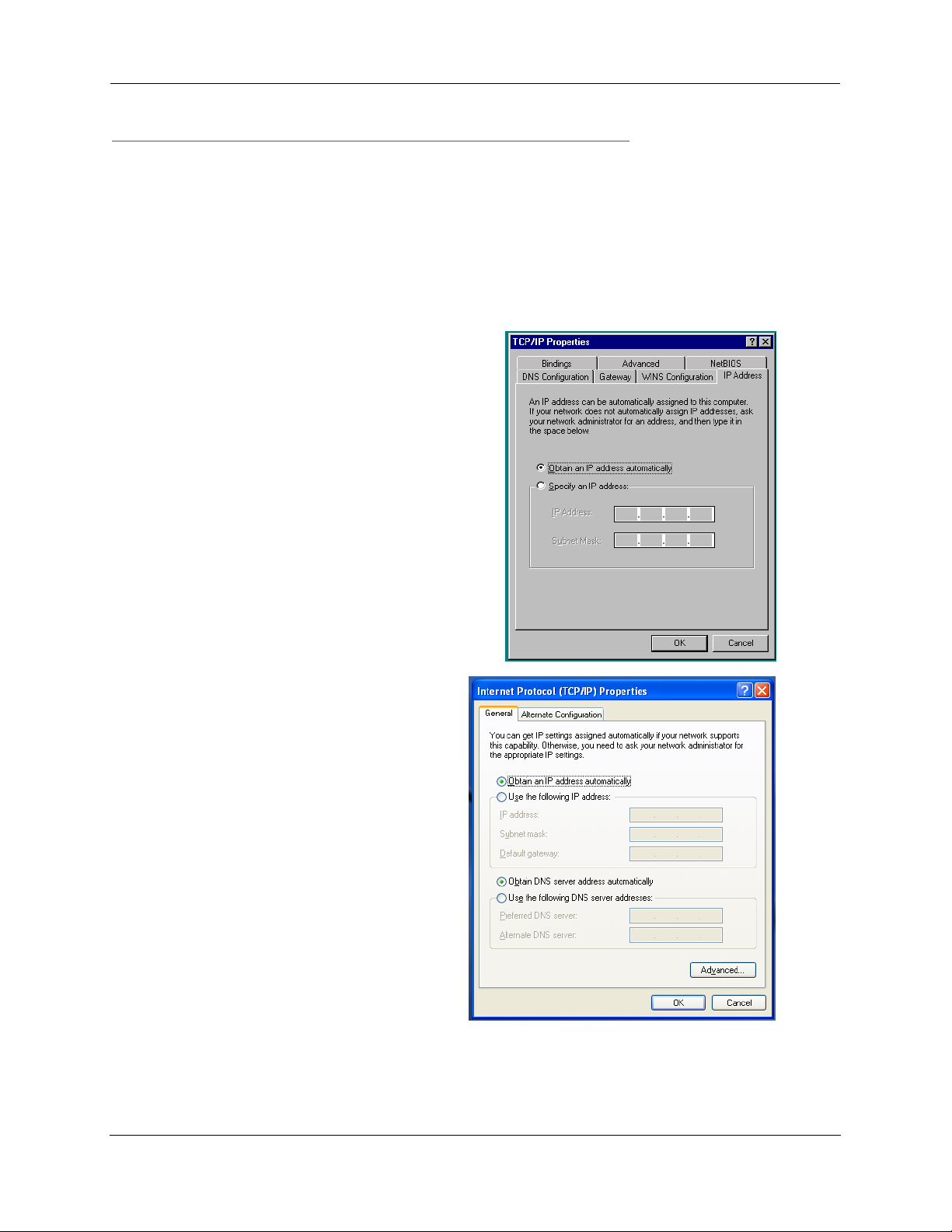
Microsoft Windows:
Step 1. Navigate to the TCP/IP Properties Control Panel.
a. Some Windows
versions follow a
path like this:
b. Some Windows
versions follow a
path like this:
Start menu -> Settings ->
Control Panel -> Network
(or Network and Dial-up
Connections -> Local Area
Connection -> Properties) > TCP/IP
[your_network_card] or
Internet Protocol [TCP/IP]
-> Properties
Start menu -> Control Panel -> Network and Internet
Connections -> Network Connections ->
Local Area Connection -> Properties ->
Internet Protocol
[TCP/IP] -> Properties
22
Page 23
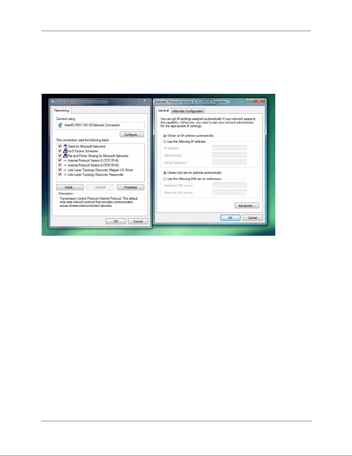
c. Windows Vista is set to obtain an IP address automatically by default. You may not need to configure it at
all.
To check, open the Networking Control Panel and select Internet Protocol Version 4 (TCP/IPv4). Click
the Properties button.
The Internet Protocol Version 4 (TCP/IPv4) Properties window should appear as shown.
If not, select the radio buttons shown above, and click the OK button.
23
Page 24
Administrator’s Handbook
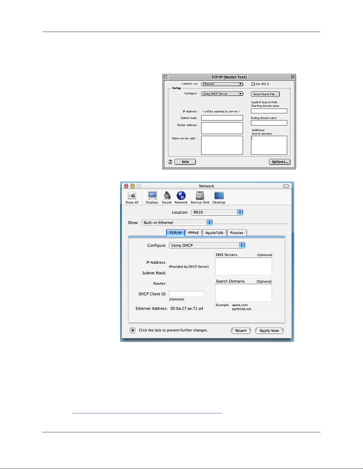
Macintosh MacOS 8 or higher or Mac OS X:
Step 1. Access the TCP/IP or Network control panel.
a. MacOS follows a
path like this:
b. Mac OS X follows
a path like this:
Apple Menu ->
Control Panels -> TCP/IP
Control Panel
Apple Menu -> System Preferences -> Network
Then go to Step 2.
Step 2. Select Built-in Ethernet
Step 3. Select Configure Using DHCP
Step 4. Close and Save, if prompted.
Proceed to “Configuring the Motorola Netopia® Gateway” on page 25.
24
Page 25
Configuring the Motorola Netopia® Gateway
1. Run your Web browser application, such as Firefox or Microsoft Internet Explorer, from
the computer connected to the Motorola Netopia® Gateway.
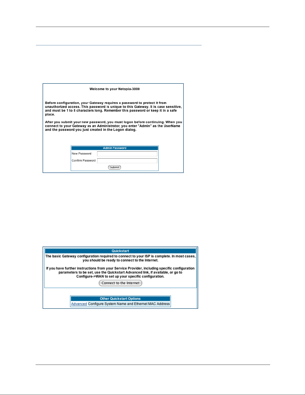
Enter http://192.168.1.254 in the Location text box.
The Admin Password page appears.
Access to your Motorola Netopia® device can be controlled through two access control accounts,
Admin or User.
• The Admin, or administrative user, performs all configuration, management or maintenance operations
on the Gateway.
• The User account provides monitor capability only.
A user may NOT change the configuration, perform upgrades or invoke maintenance functions.
For the security of your connection, an Admin password must be set on the Motorola Netopia® unit.
MiAVo VDSL and Ethernet WAN models Quickstart
The browser then displays the Quickstart page.
2. Click the
Connect to the Internet
button.
25
Page 26
Administrator’s Handbook
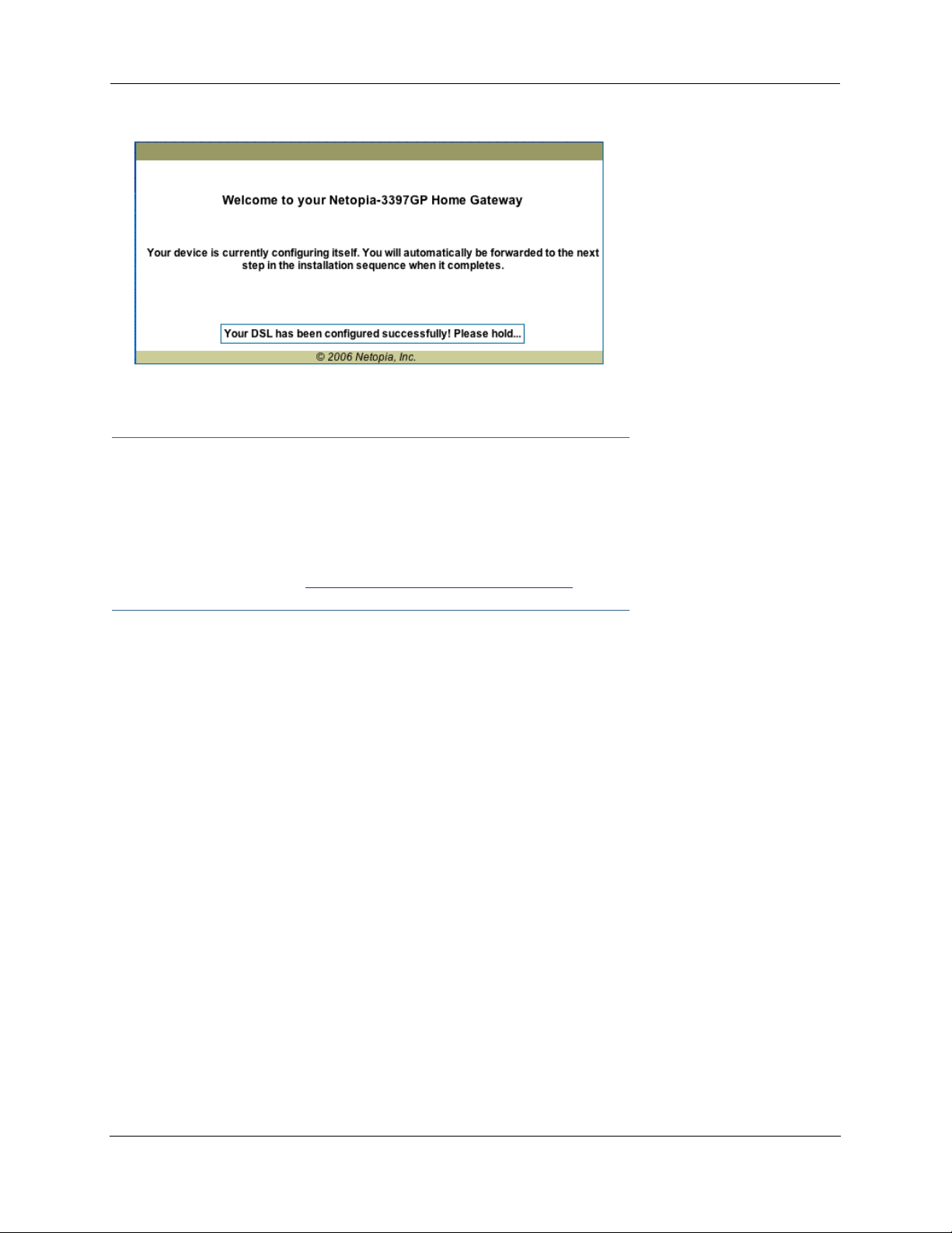
Once a connection is established, your browser is redirected to your ser vice provider’s home page or a
registration page on the Internet.
☛ NOTE:
For MiAVo Series (3397GP) models, skip the rest of this section.
Congratulations! Your configuration is complete.
You can skip to “Home Page - Basic Mode” on page 31.
26
Page 27
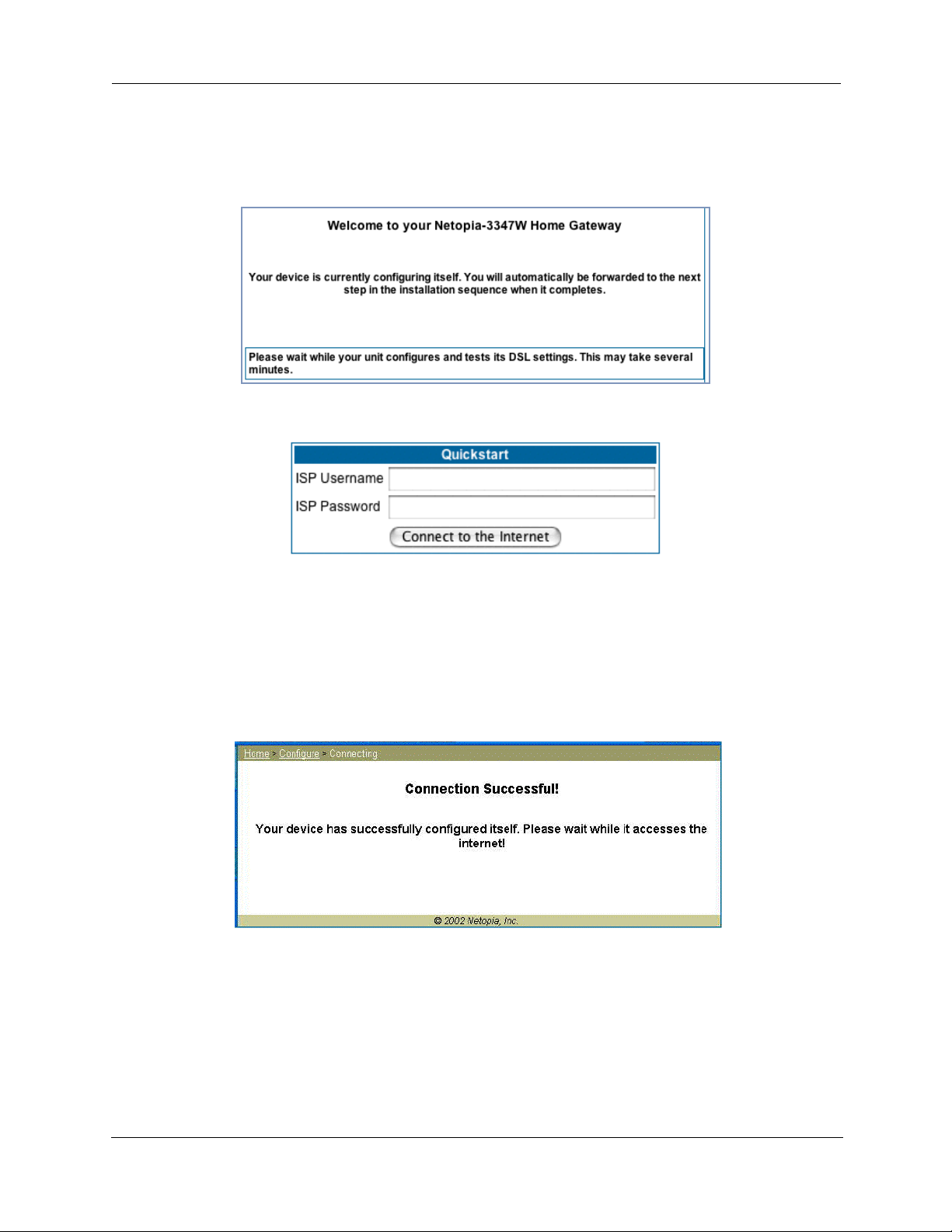
PPPoE Quickstart
For a PPPoE connection, your browser will display a different series of web pages:
The browser then displays the Quickstart web page.
3. Enter the username and password supplied by your Internet Service Provider. Click the
Connect to the Internet
Once you enter your username and password here, you will no longer need to enter them whenever you
access the Internet. The Motorola Netopia® Gateway stores this information and automatically connects
you to the Internet.
The Gateway displays a message while it configures itself.
4. When the connection succeeds, your browser will display a success message.
button.
Once a connection is established, your browser is redirected to your ser vice provider’s home page or a
registration page on the Internet.
5. Congratulations! Your installation is complete. You can now surf to your favorite Web
sites by typing an URL in your browser’s location box or by selecting one of your favorite Internet bookmarks.
27
Page 28
Administrator’s Handbook
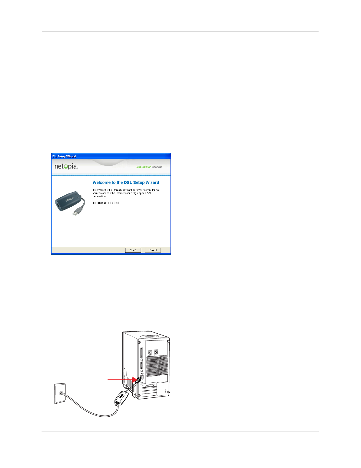
Set up the Motorola Netopia® Pocket Gateway
Your Motorola Netopia® 3342N/3352N Pocket Gateway comes with its own installation wizard.
• If you are using Windows 98, insert the CD.
• If you are using Windows XP, Windows 2000, Windows NT or Windows Vista, you don’t even need the
CD.
Follow these easy setup steps:
1. Plug the Motorola Netopia® Pocket Gateway into a USB port on your PC.
2. Whether you use the CD (Windows 98) or not (all other Windows versions), on Windows-based
PCs, the Motorola Netopia® Installation Wizard will launch automatically.
The Motorola Netopia® Installation Wizard will assist you to configure your PC to work with the Motorola
Netopia® pocket Gateway. Follow the on-screen instructions.
To proceed, click the
Next
button.
The Motorola Netopia® Installation Wizard per forms a series of checks on your system and then will
install USB drivers for your connection.
3. Place the Motorola Netopia® Pocket Gateway near your PC so you can see it easily.
Make sure any cables are kept away from power cords, fluorescent lighting fixtures, and other sources
of electrical interference.
4. When the wizard prompts you, connect the RJ-11 Telephone Cable from the DSL port on the
Motorola Netopia® Pocket Gateway to the ADSL phone jack.
The DSL indicator light should blink for up to two minutes and then come on solid green once the device
is connected to your computer.
phone jack
RJ-11 phone cable
USB port
Netopia Pocket Gateway/
28
Page 29

The Wizard displays a success message when the settings are configured.
5. The Motorola Netopia® Installation Wizard will then launch your web browser and display the
Welcome
page where you configure your Motorola Netopia® Pocket Gateway.
29
Page 30

Administrator’s Handbook
Motorola Netopia® Gateway Status Indicator Lights
Colored LEDs on your Motorola Netopia® Gateway indicate the status of various por t activity. Different
Gateway models have different ports for your connections and different indicator LEDs. The Quickstar t
Guide accompanying your Motorola Netopia® Gateway describes the behavior of the various indicator LEDs.
Example status indicator lights
Status Indicator Lights (LEDs)
netopia
30
Page 31

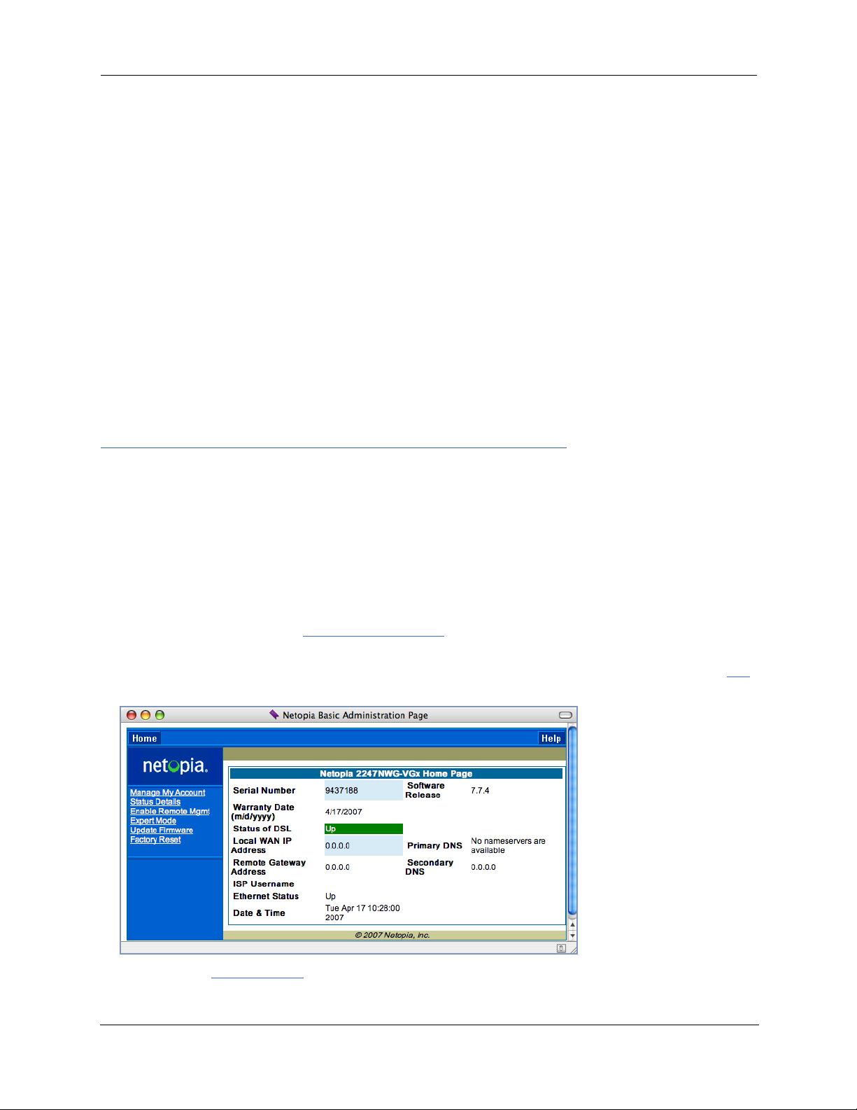
Home Page - Basic Mode
After you have performed the basic Quickstart configuration, any time you log in to your Motorola Netopia®
Gateway you will access the Motorola Netopia® Gateway Home Page.
You access the Home Page by typing
The Basic Mode Home Page appears.
http://192.168.1.254
in your Web browser’s location box.
☛ VoIP-enabled Gateways also display VoIP phone information, as well.
31
Page 32

Administrator’s Handbook
The Home Page displays the following information in the center section:
Item Description
Serial Number
Software
Release
Warranty Date
Status of DSL
Status of
Connection
Local WAN IP
Address
Remote
Gateway
Address
Primary DNS
Secondary DNS
ISP Username
Ethernet Status
This is the unique serial number of your Gateway.
This is the version number of the current embedded software in your Gateway.
This is the date that your Gateway was installed and enabled.
DSL connection (Internet) is either Up or Down
‘Waiting for DSL’ is displayed while the Gateway is training. This should
change to ‘Up’ within two minutes.
‘Up’ is displayed when the ADSL line is synched and the PPPoE session is
established.
‘Down’ indicates inability to establish a connection; possible line failure.
This is the negotiated address of the Gateway’s WAN interface. This
address is usually dynamically assigned.
This is the negotiated address of the remote router to which this Gateway
is connected.
These are the negotiated DNS addresses.
This is your PPPoE username as assigned by your service provider.
(if so equipped) Local Area Network (Ethernet) is either Up or Down
USB Status
Line 1/2
Registration
Date & Time
If your Gateway is so equipped, Local Area Network (USB) is either Up or
Down
If your Gateway is so equipped, voice Line 1 and/or 2 is either Idle or Connected
This is the current UTC time; blank if this is not available due to lack of a
network connection.
The links in the left-hand column on this page allow you to manage or configure several features of your
Gateway. Each link is described in its own section.
32
Page 33

Link: Manage My Account
You can change your ISP account information for the Motorola Netopia® Gateway. You can also manage
other aspects of your account on your service provider’s account management Web site.
Click on the
If you have a PPPoE account, enter your username, and then your new password. Confirm your new password. For security, your actual passwords are not displayed on the screen as you type. You must enter the
new password twice to be sure you have typed it correctly.
Click the
Manage My Account
Submit
button.
link. The Manage My Account page appears.
If you have a non-PPPoE account, click the OK button.
You will be taken to your ser vice provider’s Web site account management page.
33
Page 34

Administrator’s Handbook
Link: Status Details
If you need to diagnose any problems with your Motorola Netopia® Gateway or its connection to the Internet, you can run a sophisticated diagnostic tool. It checks several aspects of your physical and electronic
connection and reports its results on-screen. This can be useful for troubleshooting, or when speaking with
a technical support technician.
Click on the
Click the
see “Diagnostics” on page 217.
Status Details
Run Diagnostics
link. The Diagnostics page appears.
button to run your diagnostic tests. For a detailed description of these tests,
34
Page 35

Link: Enable Remote Management
This link allows you to authorize a remotely-located person, such as a support technician, to directly access
your Motorola Netopia® Gateway. This is useful for fixing configuration problems when you need expert
help. You can limit the amount of time such a person will have access to your Gateway. This will prevent
unauthorized individuals from gaining access after the time limit has expired.
Click the
Since you’ve already has entered an Admin password, you can use that Admin password or enter a new
password. If you enter a new password, it becomes the temporar y Admin password. After the time-out
period has expired, the Admin password rever ts to the original Admin password you entered.
Enter a temporary password for the person you want to authorize, and confirm it by typing it again. You can
select a time-out period for this password, from 5 to 30 minutes, from the pull-down menu. Be sure to tell
the authorized person what the password is, and for how long the time-out is set. Click the OK button.
Enable Rmt Mgmt
link. The Enable Remote Management page appears.
35
Page 36

Administrator’s Handbook
Link: Expert Mode
Most users will find that the basic Quickstart configuration is all that they ever need to use. Some users,
however, may want to do more advanced configuration. The Motorola Netopia® Gateway has many
advanced features that can be accessed and configured through the Exper t Mode pages.
Click the
You should carefully consider any configuration changes you want to make, and be sure that your service
provider supports them.
Once you click the OK button you will be taken to the Expert Mode Home Page.
The Expert Mode Home Page is the main access point for configuring and managing the advanced features
of your Gateway. See “Expert Mode” on page 39 for information.
Expert Mode
link to display the Expert Mode Confirmation page.
36
Page 37

Link: Update Firmware
☛ NOTE:
(This link is not available on the 3342/3352 models, since firmware updates must be
upgraded via the USB host driver.
3342N/3352N models do support this feature.)
Periodically, the embedded firmware in your Gateway may be updated to improve the operation or add new
features. Your gateway includes its own onboard installation capability. Your service provider may inform
you when new firmware is available, or you can check for yourself.
Click the
If you click the
revision. If a newer version is found, your firmware will be automatically updated once you confirm the
installation.
Update Firmware
Continue
button, the Gateway will check a remote Firmware Ser ver for the latest firmware
link. The Firmware Update Confirmation page appears.
37
Page 38

Administrator’s Handbook
Link: Factory Reset
In some cases, you may need to clear all the configuration settings and start over again to program the
Motorola Netopia® Gateway. You can perform a factory reset to do this.
Click on
Factory Reset
☛ NOTE:
Exercise caution before per forming a Factor y Reset. This will erase any configuration changes
that you may have made and allow you to reprogram your Gateway.
to reset the Gateway back to its original factory default settings.
38
Page 39
CHAPTER 3 Expert Mode
Using the Expert Mode Web-based user interface for the Motorola Netopia® 2200-, 3300- and 7000-series
Gateway you can configure, troubleshoot, and monitor the status of your Gateway.
Accessing the Expert Web Interface
Open the Web Connection
Once your Gateway is powered up, you can use any recent version of the best-known web browsers such as
Netscape Navigator or Microsoft Internet Explorer from any LAN-attached PC or workstation. The procedure
is:
1. Enter the name or IP address of your Motorola Netopia® Gateway in the Web browser's
window and press Return.
For example, you would enter http://192.168.1.254.
2. If an administrator or user password has been assigned to the Motorola Netopia® Gate-
way, enter
The Basic Mode Home Page opens.
3. Click on the Expert Mode link in the left-hand column of links.
Admin
or
User
as the username and the appropriate password and click OK.
39
Page 40

Administrator’s Handbook
You are challenged to confirm your choice.
Click OK.
The Home Page opens in Expert Mode.
40
Page 41
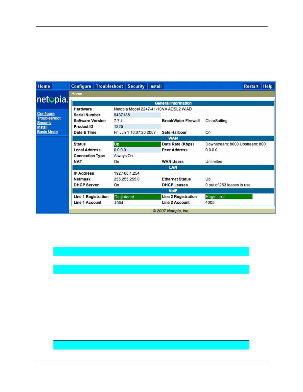
Home Page - Expert Mode
The Home Page is the summary page for your Motorola Netopia® Gateway. The toolbar at the top provides
links to controlling, configuring, and monitoring pages. Critical configuration and operational status is displayed in the center section.
Home Page - Information
The Home page’s center section contains a summary of the Gateway’s configuration settings and operational status.
Summary Information
Field Status and/or Description
General Information
Hardware Model number and summary specification
Serial Number Unique serial number, located on label attached to bottom of unit
Software Version Release and build number of running Motorola Netopia® Operating System.
Product ID Refers to internal circuit board series; useful in determining which software
upgrade applies to your hardware type.
Date & Time This is the current UTC time; blank if this is not available due to lack of a
network connection.
Breakwater Firewall If the optional feature key is installed: Status of the Breakwater Firewall:
ClearSailing, SilentRunning, or LANdLocked.
Safe Harbour If the optional feature key is installed: SafeHarbour VPN IPsec Tunnel option
(if installed): either On or Off.
WAN
41
Page 42

Administrator’s Handbook
Status Wide Area Network may be Waiting for DSL (or other waiting status), Up or
Data Rate (Kbps) Once connected, displays DSL speed rate, Downstream and Upstream
Local Address IP address assigned to the WAN port.
Peer Address The IP address of the gateway to which the connection defaults. If doing
Connection Type May be either Instant On or Always On.
NAT On or Off. ON if using Network Address Translation to share the IP address
WAN Users Displays the number of users allotted and the total number available for
IP Address Internal IP address of the Motorola Netopia® Gateway.
Netmask Defines the IP subnet for the LAN
DHCP Server On or Of f. ON if using DHCP to get IP addresses for your LAN client
DHCP Leases A “lease” is held by each LAN client that has obtained an IP address through
Ethernet (or USB)
Status
Line 1/2 Registration If your Gateway is so equipped, voice Line 1 and/or 2 is either Idle or Reg-
Down
DHCP, this info will be acquired. If doing PPP, this info will be negotiated.
across many LAN users.
use.
LAN
Default is 255.255.255.0 for a Class C device
machines.
DHCP.
Status of your Ethernet network connection (if supported). Up or Down.
VoIP
istered
42
Page 43

Toolbar
The toolbar is the dark blue bar at the top of the page containing the major navigation buttons. These buttons are available from almost ever y page, allowing you to move freely about the site.
Home Configure Troubleshoot Security Install Restart Help
Quickstart System Status Passwords Install Certificate
LAN Network Tools Firewall Install Key
WAN Diagnostics IPSec Install Software
Advanced Stateful Inspection
Packet Filter
Security Log
Navigating the Web Interface
Link: Breadcrumb Trail
The breadcrumb trail is built in the light brown area beneath the toolbar. As you navigate down a path within
the site, the trail is built from left to right. To return anywhere along the path from which you came, click on
one of the links.
43
Page 44
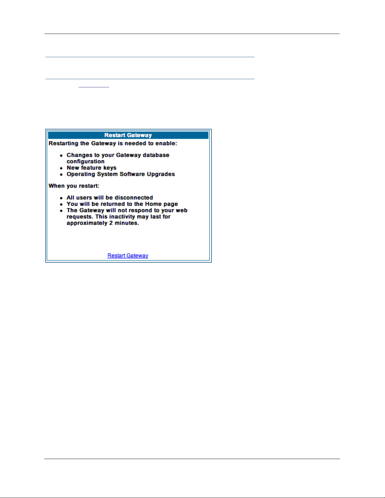
Administrator’s Handbook
Restart
Button: Restart
The Restart button on the toolbar allows you to restart the Gateway at any time. You will be prompted to
confirm the restar t before any action is taken. The Restar t Confirmation message explains the consequences of and reasons for restarting the Gateway.
44
Page 45
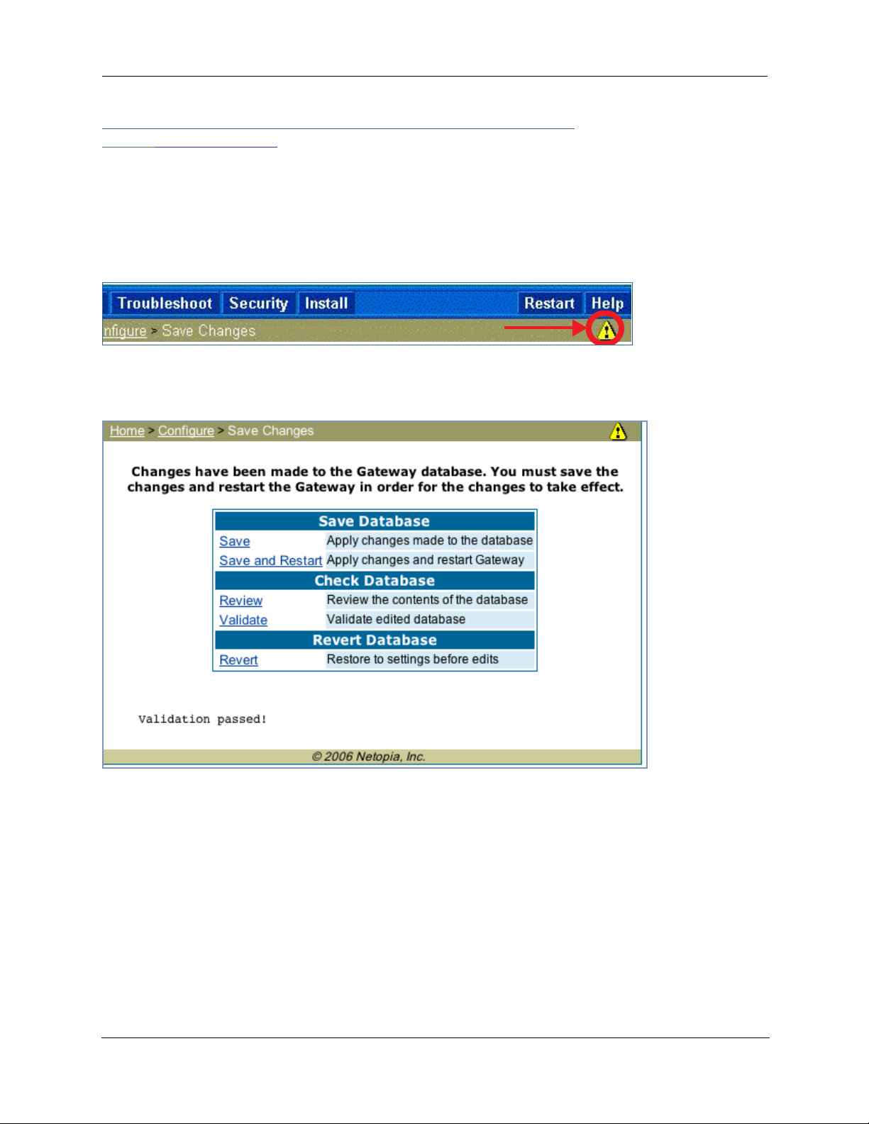
Link: Alert Symbol
The Alert symbol appears in the upper right corner if you make a database change; one in which a change
is made to the Gateway’s configuration. The Alert serves as a reminder that you must Save the changes
and Restart the Gateway before the change will take effect. You can make many changes on various
pages, and even leave the browser for up to 5 minutes, but if the Gateway is restar ted before the changes
are applied, they will be lost. When you click on the Alert symbol, the Save Changes page appears. Here
you can select various options to save or discard these changes.
If more than one Alert is triggered, you will need to take action to clear the first Alert before you can see the
second Alert.
45
Page 46

Administrator’s Handbook
Help
Button: Help
Context-sensitive Help is provided in your Gateway. The page shown here is displayed when you are on the
Home page or other transitional pages. To see a context help page example, go to Security -> Pass-
words, then click Help.
46
Page 47

Configure
Button: Configure
The Configuration options are presented in the order of likelihood you will need to use them. Quickstart is
typically accessed during the hardware installation and initial configuration phase. Often, these settings
should be changed only in accordance with information from your Service Provider. LAN and WAN
settings are available to fine-tune your system. Advanced provides some special capabilities typically used
for gaming or small office environments, or where LAN-side servers are involved.
☛ This button will not be available if you log on as User.
Link: Quickstart
How to Use the Quickstart Page. Quickstart is normally used immediately after the new hardware
is installed. When you are first configuring your Gateway, Quickstart appears first.
(Once you have configured your Gateway, logging on displays the Home page. Thereafter, if you need to use
Quickstart, choose it from the Expert Mode Configure menu.)
Setup Your Gateway using a PPP Connection.
This example screen is the for a PPP Quickstart configuration. Your gateway authenticates with the Service Provider equipment using the ISP Username and Password. These values are given to you by your Service Provider.
1. Enter your ISP Username and ISP Password.
2. Click Connect to the Internet.
47
Page 48

Administrator’s Handbook
A brief message is displayed while the Gateway attempts to establish a connection.
3. When the connection succeeds, your browser will display your Service Provider’s
home page.
If you encounter any problems connecting, refer to the chapters “Basic Troubleshooting” on page 193 or
“Advanced Troubleshooting” on page 207.
48
Page 49

Link: LAN
* Enable Interface: Enables all LAN-connected computers to share resources and to connect to the WAN.
The Interface should always be enabled unless you are instructed to disable it by your Ser vice Provider during troubleshooting.
* IP Address: The LAN IP Address of the Gateway. The IP Address you assign to your LAN interface must
not be used by another device on your LAN network.
* IP Netmask: Specifies the subnet mask for the TCP/IP network connected to the virtual circuit. The subnet mask specifies which bits of the 32-bit binary IP address represent network information. The default
subnet mask for most networks is 255.255.255.0 (Class C subnet mask.)
* Restrictions: Specifies whether an administrator can open a Web Administrator or Telnet connection to
the Gateway over the LAN interface in order to monitor and configure the Gateway. On the LAN Interface,
you can enable or disable administrator access. By default, administrative restrictions are turned of f,
meaning an administrator can open a Web Administrator or Telnet connection through the LAN Inter face.
• Advanced: Clicking on the Advanced link displays the Advanced LAN IP Interface page.
49
Page 50

Administrator’s Handbook
• IGMP Forwarding: The default setting is Disabled. If you check this option, it will enable Internet Group
Management Protocol (IGMP) multicast forwarding. IGMP allows a router to determine which host groups
have members on a given network segment. See “IGMP (Internet Group Management Protocol)” on
page 100 for more information.
• RIP Send Mode: Specifies whether the gateway should use Routing Information Protocol (RIP) broad-
casts to advertise its routing tables to other routers on your network. You may choose from the following
protocols:
• RIP-1: Routing Information Protocol version 1
• RIP-2: RIP Version 2 is an extension of the original Routing Information Protocol (RIP-1) that expands
the amount of useful information in the RIP packets. While RIP-1 and RIP-2 share the same basic algorithms, RIP-2 supports several new features, including inclusion of subnet masks in RIP packets and
implementation of multicasting instead of broadcasting (which reduces the load on hosts which do not
support routing protocols.
• RIP-1 compatibility: Compatible with RIP version 1
• RIP-2 with MD5: MD5 authentication is an extension of RIP-2 that increases security by requiring an
authentication key when routes are adver tised.
• RIP MD5 Key: Secret password when using RIP-2 with MD5.
• RIP Receive Mode: Specifies whether the Gateway should use Routing Information Protocol (RIP)
broadcasts to update its routing tables with information received from other routers on your network.
The protocol choices are the same as for the RIP send mode.
• Proxy ARP: Specifies whether you want the Gateway to respond when it receives an address resolution
protocol for devices behind it. This is a way to make a computer that is physically located on one network appear to be part of a different physical network connected to the same Gateway. It allows you to
hide a computer with a public IP address on a private network behind your Gateway, and still have the
computer appear to be on the public network “in front of” the Gateway.
• Static Client Address Translation: If you check this checkbox, this feature allows a statically
addressed computer whose IP address falls outside of the LAN subnet(s) to simply plug in and get
online without any manual configuration on either the host or the Motorola Netopia® Gateway. If
enabled, statically addressed LAN hosts that have an address outside of LAN subnets will be able to
communicate via the Router’s WAN interface to the Internet. Supported static IP address values must
fall outside of the Router's LAN subnet(s).
• IP Subnets: The IP Subnets screen allows you to configure up to seven secondar y subnets and their
DHCP ranges, by entering IP address/subnet mask pairs:
50
Page 51

☛ Note:
You need not use this screen if you have only a single Ethernet IP subnet.
This screen displays seven rows of editable columns. All seven row labels are always visible, regardless of
the number of subnets configured.
• To add an IP subnet, select one of the rows, and click the Edit button.
Check the Enabled checkbox and click the Submit button.
The screen expands to allow you to enter subnet information.
If DHCP Server (see below) is not enabled, the DHCP Start Address and DHCP End Address fields do
not appear.
• Enter the Router’s IP address on the subnet in the IP Address field and the subnet mask for the subnet
in the Netmask field.
• Enter the DHCP Start Address and End Address of the subnet range in their respective fields.
Ranges cannot overlap and there may be only one range per subnet.
• Click the Submit button.
• When you are finished adding subnets, click the Alert icon at the upper right, and in the resulting page,
click the Save and Restart link.
To delete a configured subnet, set both the IP address and subnet mask values to 0.0.0.0, either explicitly
or by clearing each field and clicking the Submit button to commit the change.
☛ NOTE:
All additional DHCP ranges use the global lease period value. See page 52.
51
Page 52
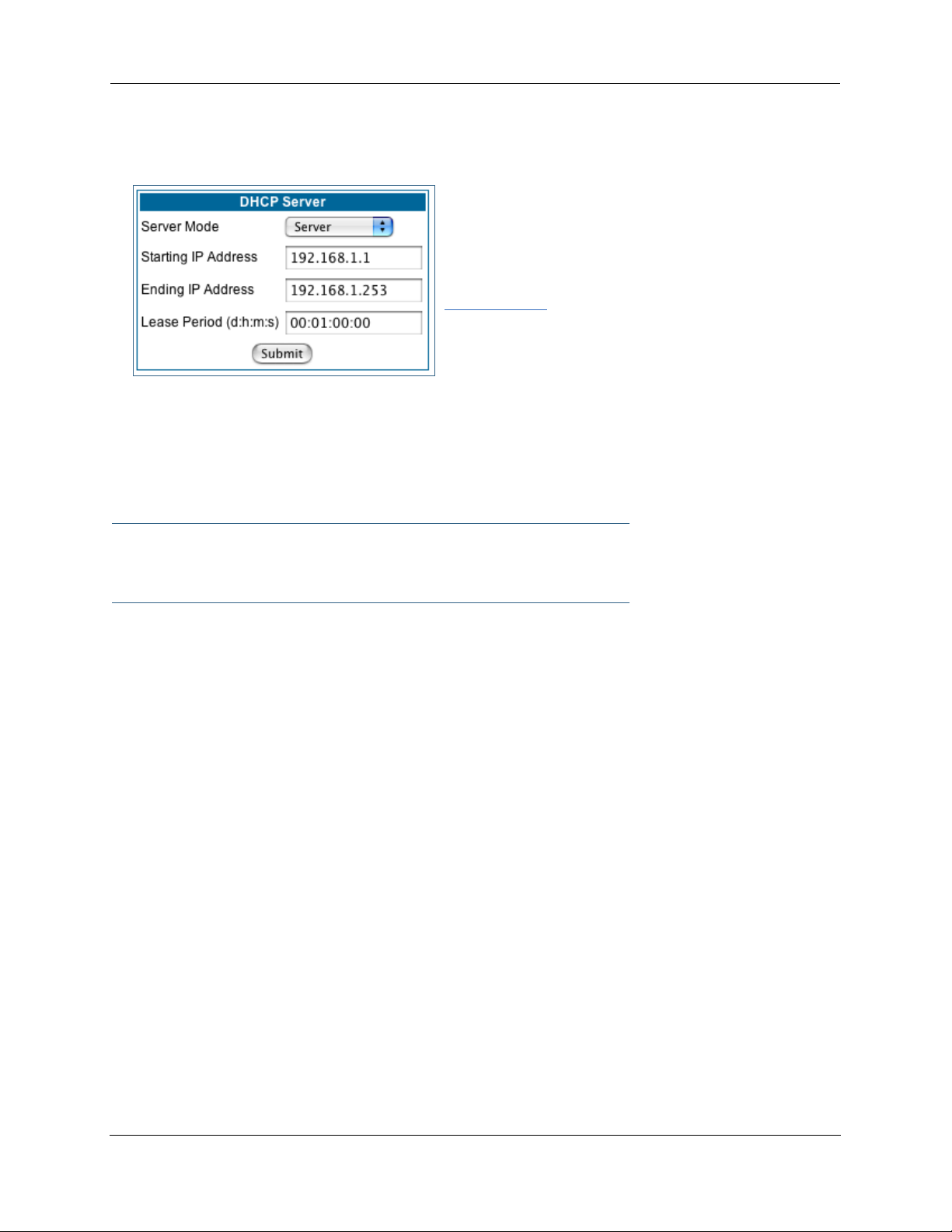
Administrator’s Handbook
• DHCP Server: Your Gateway can provide network configuration information to computers on your LAN,
using the Dynamic Host Configuration Protocol (DHCP).
If you already have a DHCP server on your LAN, you should
turn this service off.
If you want the Gateway to provide this service, click the
Server Mode pull-down menu, choose Server, then con-
figure the range of IP addresses that you would like the
Gateway to hand out to your computers.
You can also specify the length of time the computers can
use the configuration information; DHCP calls this period the lease time.
Your Ser vice Provider may, for certain services, want to provide configuration from its DHCP servers to the
computers on your LANs. In this case, the Gateway will relay the DHCP requests from your computers to a
DHCP server in the Service Provider's network. Click the relay-agent and enter the IP address of the Service
Provider's DHCP server in the Server Address field. This address is furnished by the Ser vice Provider.
☛ NOTE:
The Relay-agent option only works when NAT is off and the Gateway is in router mode.
52
Page 53

Wireless
(supported models)
If your Gateway is a wireless model (such as a 3347W) you can enable or disable the wireless LAN (WLAN)
by clicking the Wireless link.
Wireless functionality is enabled by default.
If you uncheck the Enable Wireless checkbox, the Wireless Options are disabled, and the Gateway will not
provide or broadcast any wireless LAN ser vices.
SSID (Network ID): The SSID is preset to a number that is unique to your unit. You can either leave it as is,
or change it by entering a freeform name of up to 32 characters, for example “Ed’s Wireless LAN”. On client
PCs’ software, this might also be called the Network Name. The SSID is used to identify this particular wireless LAN. Depending on their operating system or client wireless card, users must either:
• select from a list of available wireless LANs that appear in a scanned list on their client
• or, if you are in Closed System Mode (see Enable Closed System Mode below), enter this name on
their clients in order to join this wireless LAN.
The pull-down menu for enabling Privacy offers four settings: WPA-802.1x, WPA-PSK, WEP - Automatic,
and Off - No Privacy. WEP-Manual is also available on the Advanced Configuration Options page. See “Pri-
vacy” on page 54.
☛ NOTE:
On the 2200-Series Gateways, WEP-Manual privacy is enabled by default. Use the Motorola
Netopia® Installation Wizard on the accompanying Motorola Netopia® CD to generate WEP
keys for connecting wireless client computers.
53
Page 54

Administrator’s Handbook
Privacy
• Off - No Privacy provides no encryption on your wireless LAN data.
• WPA-802.1x provides RADIUS ser ver authentication suppor t.
• WPA-PSK provides Wireless Protected Access, the most secure option for your wireless network. This
mechanism provides the best data protection and access control.
The Pre Shared Key is a passphrase shared between the Router and the clients and is used to generate dynamically changing keys. The passphrase can be 8-63 characters or up to 64 hex characters. It is
recommended to use at least 20 characters for best security.
• WEP - Automatic is a passphrase generator. You enter a passphrase that you choose in the Pass-
phrase field. The passphrase can be any string of words or numbers.
You can provide a level of data security by enabling WEP (Wired Equivalent Privacy) for encryption of network data. You can enable 40-, 128-, or 256-bit WEP Encr yption (depending on the capability of your client wireless card) for IP traffic on your LAN.
54
Page 55

You select a single key for encr yption of outbound traffic. The WEP-enabled client must have an identical
key of the same length, in the identical slot (1 – 4) as the Gateway, in order to successfully receive and
decrypt the traffic. Similarly, the client also has a ‘default’ key that it uses to encrypt its transmissions.
In order for the Gateway to receive the client’s data, it must likewise have the identical key of the same
length, in the same slot. For simplicity, a Gateway and its clients need only enter, share, and use the
first key.
Click the Submit button. The Alert icon appears.
Click the Alert icon, and then the Save and Restart link.
55
Page 56
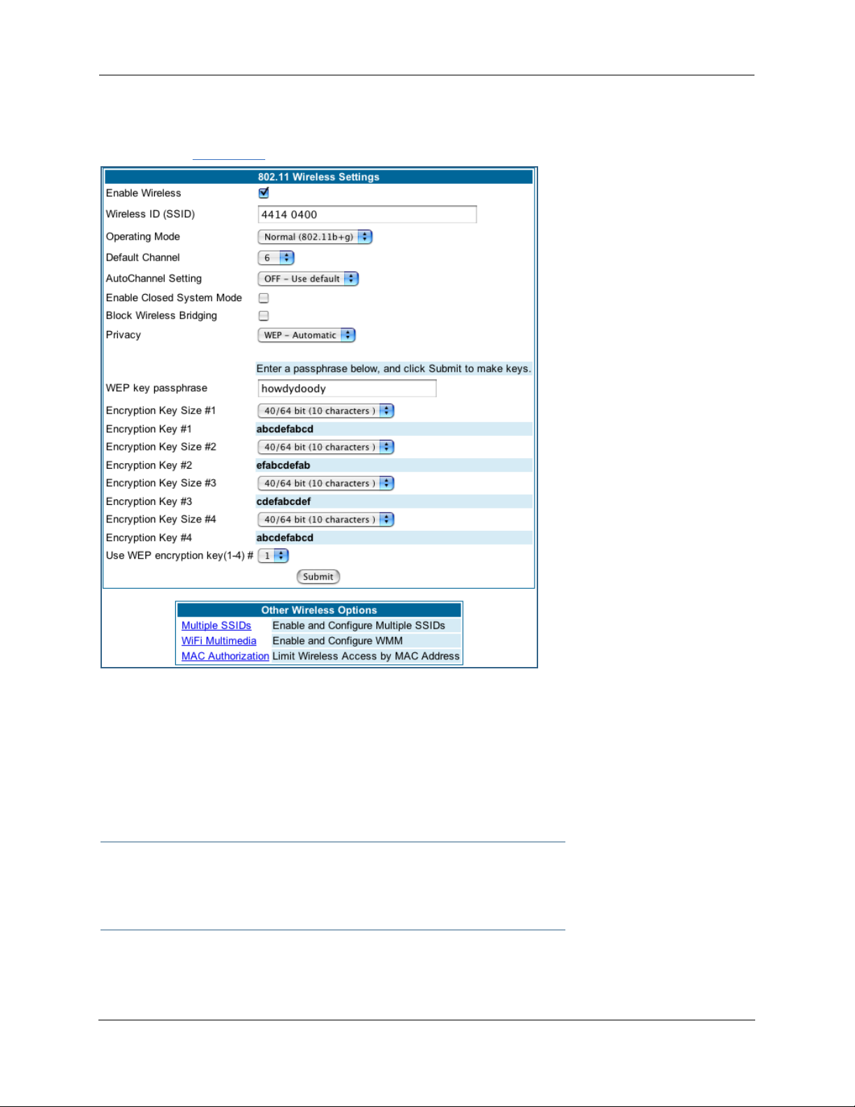
Administrator’s Handbook
Advanced
If you click the Advanced link, the advanced 802.11 Wireless Settings page appears.
Note: This page displays different options depending on which form of Privacy or other options you have
enabled.
You can then configure:
Operating Mode: The pull-down menu allows you to select and lock the Gateway into the wireless transmission mode you want. For compatibility with clients using 802.11b (up to 11 Mbps transmission) and
802.11g (up to 20+ Mbps), select Normal (802.11b + g). To limit your wireless LAN to one mode or the
other, select 802.11b Only, or 802.11g Only.
☛ NOTE:
If you choose to limit the operating mode to 802.11b or 802.11g only, clients using the mode
you excluded will not be able to connect.
Default Channel: on which the network will broadcast. This is a frequency range within the 2.4Ghz band.
Channel selection depends on government regulated radio frequencies that var y from region to region. The
widest range available is from 1 to 14. However, in North America only 1 to 11 may be selected. Europe,
56
Page 57

France, Spain and Japan will differ. Channel selection can have a significant impact on performance,
depending on other wireless activity close to this Gateway. Channel selection is not necessary at the client
computers; the clients will scan the available channels seeking access points using the same SSID as the
client.
AutoChannel Setting: For 802.11G models, AutoChannel is a feature that allows the Motorola Netopia®
Gateway to determine the best channel to broadcast automatically.
Three settings are available from the pull-down menu: Off-Use default, At Startup, and Continuous.
• Off-Use default is the default setting; the Motorola Netopia® Gateway will use the configured default
channel selected from the previous pull-down menu.
• At Startup causes the Motorola Netopia® Gateway at star tup to briefly initialize on the default channel,
then perform a full two- to three-second scan, and switch to the best channel it can find, remaining on
that channel until the next reboot.
• Continuous performs the at-startup scan, and will continuously monitor the current channel for any
other Access Point beacons. If an Access Point beacon is detected on the same channel, the Motorola
Netopia® Gateway will initiate a three- to four-minute scan of the channels, locate a better one, and
switch. Once it has switched, it will remain on this channel for at least 30 minutes before switching
again if another Access Point is detected.
Enable Closed System Mode: If enabled, Closed System Mode hides the wireless network from the scanning features of wireless client computers. Unless both the wireless clients and the Router share the same
SSID in Closed System mode, the Router’s wireless LAN will not appear as an available network when
scanned for by wireless-enabled computers. Members of the Closed System WLAN must log onto the
Router’s wireless network with the identical SSID as that configured in the router.
Closed System mode is an ideal way to increase wireless security and to prevent casual detection by
unwanted neighbors, office users, or malicious users such as hackers.
If you do not enable Closed System Mode, it is more convenient, but potentially less secure, for clients to
access your WLAN by scanning available access points. You must decide based on your own network
requirements.
About Closed System Mode
Enabling Closed System Mode on your wireless Gateway provides another level of security, since your wireless LAN will no longer appear as an available access point to client PCs that are casually scanning for one.
Your own wireless network clients, however, must log into the wireless LAN by using the exact SSID of the
Motorola Netopia® Gateway.
In addition, if you have enabled WEP encryption on the Motorola Netopia® Gateway, your network clients
must also have WEP encryption enabled, and must have the same WEP encryption key as the Motorola
Netopia® Gateway.
Once the Motorola Netopia® Gateway is located by a client computer, by setting the client to a matching
SSID, the client can connect immediately if WEP is not enabled. If WEP is enabled then the client must also
have WEP enabled and a matching WEP key.
Wireless client cards from dif ferent manufacturers and dif ferent operating systems accomplish connecting
to a wireless LAN and enabling WEP in a variety of ways. Consult the documentation for your particular wireless card and/or operating system.
57
Page 58
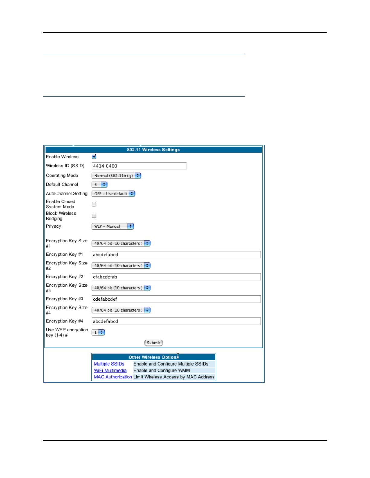
Administrator’s Handbook
☛ NOTE:
While clients may also have a passphrase feature, these are vendor-specific and may not necessarily create the same keys. You can passphrase generate a set of keys on one, and manually enter them on the other to get around this.
Block Wireless Bridging: Check the checkbox to block wireless clients from communicating with other
wireless clients on the LAN side of the Gateway.
• WEP - Manual allows you to enter your own encryption keys manually. This is a dif ficult process, but
only needs to be done once. Avoid the temptation to enter all the same characters.
Encryption Key Size #1 – #4: Selects the length of each encryption key. The longer the key, the stronger
the encryption and the more difficult it is to break the encryption.
58
Page 59

Encryption Key #1 – #4: The encryption keys. You enter keys using hexadecimal digits. For 40/64bit
encryption, you need ten digits; 26 digits for 128bit, and 58 digits for 256bit WEP. Hexadecimal characters
are 0 – 9, and a – f.
Examples:
• 40bit: 02468ACE02
• 128bit: 0123456789ABCDEF0123456789
• 256bit: 592CA140F0A238B0C61AE162F592CA140F0A238B0C61AE162F21A09C
Use WEP encryption key (1 – 4) #: Specifies which key the Gateway will use to encrypt transmitted traf fic.
The default is key #1.
You disable the wireless LAN by unchecking the Enable Wireless checkbox, clicking the Submit button, followed by the Save and Restart link.
WPA Version Allowed
If you select either WPA-802.1x or WPA-PSK as your privacy setting, the WPA Version Allowed pull-down
menu appears to allow you to select the WPA version(s) that will be required for client connections. Choices
are:
• WPA Version 1 and 2, for maximum interoperability,
• WPA Version 1 Only, for backward compatibility,
• WPA Version 2 Only, for maximum security.
All clients must support the version(s) selected in order to successfully connect.
Multiple SSIDs
The Multiple Wireless SSIDs feature allows you to add additional network identifiers (SSIDs or Network
Names) for your wireless network.
To enable Multiple Wireless SSIDs, click the Multiple SSIDs link.
When the Multiple Wireless SSIDs screen appears, check the Enable SSID checkbox for each SSID you
want to enable.
59
Page 60

Administrator’s Handbook
The screen expands to allow you to name each additional Wireless ID, and specify a Privacy mode for each
one.
60
Page 61

Privacy modes available from the pull-down menu for the multiple SSIDs are: WPA-PSK, WPA-802.1x, or
Off-No Privacy. WEP can also be selected on the additional SSIDs as long as it is not used on the primary
SSID. WEP can only be used on one SSID, so any others will not have WEP available.
These additional Wireless IDs are “Closed System Mode” Wireless IDs that will not be shown by a client
scan, and therefore must be manually configured at the client. In addition, wireless bridging between clients
is disabled for all members of these additional network IDs.
Click the Submit button.
After your first entry, the Alert icon will appear in the upper right corner of your screen. When you are
finished adding SSIDs, click the Alert icon, and Save your changes and restart the Gateway.
61
Page 62

Administrator’s Handbook
WiFi Multimedia
WiFi Multimedia is an advanced feature that allows you to prioritize various types of data travelling over the
wireless network. Certain types of data that are sensitive to delays, such as voice or video, must be prioritized ahead of other, less delay-sensitive types, such as email.
WiFi Multimedia currently implements wireless Quality of Ser vice (QoS) by transmitting data depending on
Diffserv priority settings. These priorities are mapped into four Access Categories (AC), in increasing order
of priority:
• Background (BK),
• Best Effort (BE),
• Video (VI), and
• Voice (VO).
It requires WiFi Multimedia (WMM)-capable clients, usually a separate feature enabled at the client network
settings, and client PC software that makes use of Differentiated Services (Diffser v). Refer to your operating system instructions for enabling Diffserv QoS..
When you click the WiFi Multimedia link the WiFi Multimedia page appears.
To enable the WiFi Multimedia custom settings, select Diffserv from the pull-down menu.
62
Page 63

The screen expands.
Router EDCA Parameters (Enhanced Distributed Channel Access) govern wireless data from your Gateway to the client; Client EDCA Parameters govern wireless data from the client to your Gateway.
☛ NOTE:
It is not recommended that you modify these settings without direct knowledge or instructions
to do so. Modifying these settings inappropriately could seriously degrade network performance.
• AIFs: (Arbitration Interframe Spacing) the wait time in milliseconds for data frames.
• cwMin: (Minimum Contention Window) upper limit in milliseconds of the range for determining initial ran-
dom backoff. The value you choose must be lower than cwMax.
• cwMax: (Maximum Contention Window) upper limit in milliseconds of the range of determining final ran-
dom backoff. The value you choose must be higher than cwMin.
• TXOP Limit: Time interval in microseconds that clients may initiate transmissions.
(When Operating Mode is B-only, default values are used and this field is not configurable.)
Wireless MAC Authorization
Wireless MAC Authorization allows you to specify which client PCs are allowed to join the wireless LAN by
specific hardware address. Once it is enabled, only entered MAC addresses that have been set to Allow will
63
Page 64
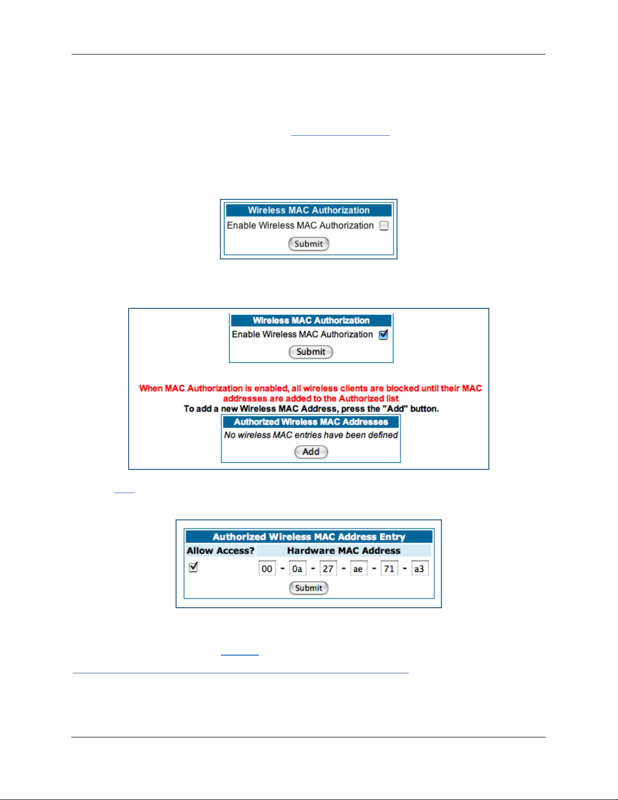
Administrator’s Handbook
be accepted onto the wireless LAN. All unlisted addresses will be blocked, in addition to the listed
addresses with Allow disabled.
To enable Wireless MAC Authentication, click the MAC Authorization link.
When the Wireless MAC Authentication screen appears, check the Enable Wireless MAC Authorization
checkbox:
The screen expands as follows:
Click the Add button. The Authorized Wireless MAC Address Entry screen appears.
Enter the MAC (hardware) address of the client PC you want to authorize for access to your wireless LAN.
The Allow Access? checkbox is enabled by default. Unchecking this checkbox specifically denies access
from this MAC address. Click the Submit button.
☛ Note:
When MAC Authorization is enabled, all wireless clients are blocked until their MAC addresses
64
Page 65

are added to the Authorized list.
Your entr y will be added to a list of up to 32 authorized addresses as shown:
You can continue to Add, Edit, or Delete addresses to the list by clicking the respective buttons.
After your first entry, the Alert icon will appear in the upper right corner of your screen. When you
are finished adding addresses to the list, click the Alert icon, and Save your changes and restar t the Gateway.
Use RADIUS Server
RADIUS servers allow external authentication of users by means of a remote authentication database. The
remote authentication database is maintained by a Remote Authentication Dial-In User Service (RADIUS)
server. In conjunction with Wireless User Authentication, you can use a RADIUS server database to authenticate users seeking access to the wireless services, as well as the authorized user list maintained locally
within the Gateway.
If you click the RADIUS link, the screen expands to allow you to enter your RADIUS server information.
65
Page 66

Administrator’s Handbook
• RADIUS Server Addr/Name: The default RADIUS server name or IP address that you want to use.
• RADIUS Server Secret: The RADIUS secret key used by this server. The shared secret should have the
same characteristics as a normal password.
• RADIUS Server Port: The port on which the RADIUS server is listening, typically, the default 1812.
Click the Submit button.
You can also configure alternate RADIUS servers from the Advanced Network Configuration page, by clicking
the Advanced link.
The Advanced Network Configuration page appears.
You access the RADIUS Ser ver configuration screen from the Advanced Network Configuration web page, by
clicking the RADIUS Server link.
66
Page 67
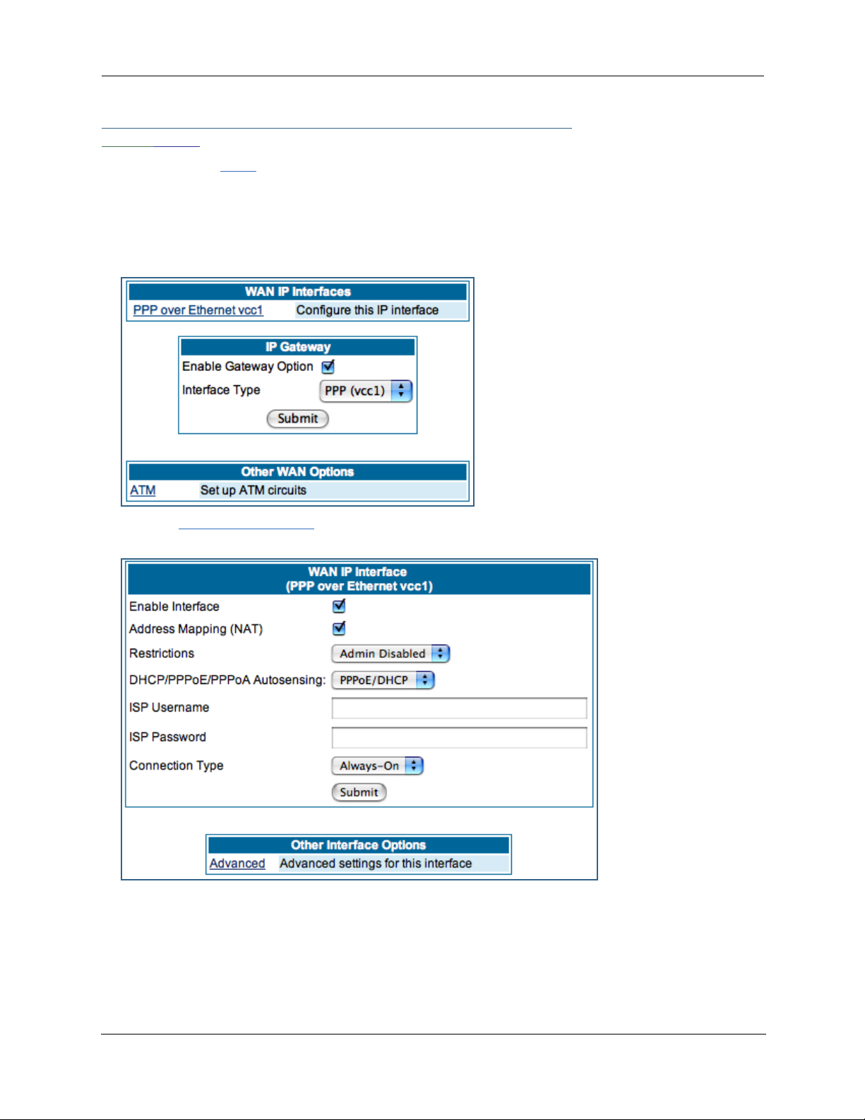
Link: WAN
When you click the WAN link, the WAN IP configuration page appears. This page varies depending on the
WAN interface of your Motorola Netopia® Gateway.
WAN IP Interfaces: Your IP inter faces are listed.
PPP over Ethernet interface
Click the PPP over Ethernet link to configure it.
The WAN IP Interface page appears.
Enable Interface: You can disable the inter face by unchecking the checkbox. However, doing so will disable all ability for your LAN users to connect to the WAN using the Gateway.
Address Mapping (NAT): Specifies whether you want the Gateway to use network address translation
(NAT) when communicating with remote routers. NAT lets you conceal details of your network from remote
routers. By default, address mapping is enabled.
67
Page 68

Administrator’s Handbook
Restrictions: This setting determines the types of traffic the Gateway accepts from the WAN. Admin Disabled means that Gateway traffic is accepted but administrative commands are ignored. None means that
all traffic is accepted. When PPP is enabled, Admin Disabled is the default.
DHCP/PPPoE/PPPoA Autosensing:
The pull-down menu allows
you to select an autosensing feature, or to disable it.
Selecting between PPPoE/
DHCP or PPPoE/PPPoA
enables automatic sensing
of your WAN connection
type. If you select PPPoE/
DHCP, the gateway
attempts to connect using
PPPoE first. If the Gateway
fails to connect after 60 seconds, it switches to DHCP. As soon as it can connect via DHCP, the Gateway
chooses and sets DHCP as its default. Otherwise, after attempting to connect via DHCP for 60 seconds,
the Gateway switches back to PPPoE. The Gateway will continue to switch back and forth in this manner
until it successfully connects. Similarly, selecting PPPoE/PPPoA causes the Gateway to attempt to con-
nect by trying these protocols in parallel, and using the first one that is successful. If you choose to disable
the feature, select Off.
ISP Username: This is the username used to authenticate your Gateway with the Service Provider's network. This value is given to you by your Service Provider.
ISP Password: This is the password used to authenticate your Gateway with the Service Provider's network. This value is given to you by your Service Provider.
Connection Type: The pull-down menu allows you to choose to have either an uninterrupted connection or
an as-needed connection.
• Always On: This setting provides convenience, but it leaves your network permanently connected to
the Internet.
• Instant On furnishes almost all the benefits of an Always On connection, but has additional security
benefits:
- Your network cannot be attacked when it is not connected.
- Your network may change address with each connection, making it more difficult to attack.
Timeout: (only appears if Instant-On Connection Type is selected) Specifies the time in seconds before disconnect if there is no traffic over the Internet link.
68
Page 69

Advanced:
If you click the Advanced link, the Advanced WAN IP Interface configuration page appears.
Local Address: If this value is 0.0.0.0, the Gateway
will acquire its IP address from your ISP. Otherwise
this address is assigned to the virtual PPP interface.
Peer Address: Address of the server on the Ser vice
Provider side of the ppp link. This peer will attempt to
negotiate the local IP address if IP Address =
0.0.0.0. If the remote peer does not accept the IP
address, the link will not come up.
RIP Receive Mode: Routing Information Protocol
(RIP) is needed if there are IP routers on other segments of your Ethernet network that the Motorola
Netopia® Gateway needs to recognize. Set to Off,
Netopia Embedded Software Version 7.7.4 will not
accept information from either RIP-1 nor RIP-2 routers. With Receive RIP Mode set to RIP-1, the Motor-
ola Netopia® Gateway will accept routing information
provided by RIP packets from other routers that use
the same subnet mask. Set to RIP-2, Netopia
Embedded Software Version 7.7.4 will accept routing
information provided by RIP packets from other routers that use different subnet masks.
From the pull-down menu, choose Off, RIP-1, RIP-2,
RIP-1 compatibility, or RIP-2 with MD5.
RIP Receive MD5 Key: (Only appears if RIP-2 with
MD5 RIP Receive Mode is selected) The purpose of MD5 authentication is to provide an additional level of
confidence that a RIP packet received was generated by a reliable source. In other words, MD5 authentication provides an enhanced level of security that information that your PC receives does not originate from a
malicious source posing as part of your network. This field allows you to enter an MD5 encryption key of
from 1 – 16 ASCII characters for authenticating RIP receipts.
Multicast Forward: If you check this checkbox, this interface acts as an IGMP proxy host, and IGMP packets are transmitted and received on this inter face on behalf of IGMP hosts on the LAN inter face.
IGMP Null Source Address: If you check this checkbox, the source IP address of every IGMP packet transmitted from this interface is set to 0.0.0.0. This complies with the requirements of TR-101, and removes
the need for a publicly advertised IP address on the WAN interface. This checkbox is only available if “Multicast Forward” is checked.
69
Page 70

Administrator’s Handbook
LCP Settings:
Authentication: Select Off, PAP and/or CHAP, PAP only, or CHAP only from the pull-down menu. The
settings for port authentication on the Gateway must match the authentication expected by the remote system. The username and passwords are available on the WAN IP Inter faces page.
MRU: Specifies the Maximum Receive Unit for the PPP Interface.
Magic Number: Enables or disables LCP magic number negotiation.
Protocol Compression: Specifies whether you want the Gateway to compress the PPP Protocol field when
it transmits datagrams over the PPP link.
LCP Echo Requests: Specifies whether you want your Gateway to send LCP echo requests. You should
turn off LCP echoing if you do not want the Gateway to drop a PPP link to a nonresponsive peer.
Max Failures: Specifies the maximum number of Configure-NAK messages the PPP module can send without having sent a Configure-ACK message.
Max Configures: Specifies the maximum number of unacknowledged configuration requests that your
Gateway will send.
Max Terminates: Specifies the maximum number of unacknowledged termination requests that your Gateway will send before terminating the PPP link.
Restart Timer: The number of seconds the Gateway should wait before retransmitting a configuration or
termination request.
Click the Submit button when you are finished.
Ethernet WAN interface
Click the Ethernet WAN link to configure it.
70
Page 71

The WAN IP Interface page appears.
Enable Interface: You can disable the inter face by unchecking the checkbox. However, doing so will dis-
able all ability for your LAN users to connect to the WAN using the Gateway.
Obtain IP Address Automatically: Your ser vice provider may tell you that the WAN IP Address for your
Gateway is static. In this case, disable this checkbox and enter the IP Address and IP Netmask from your
Service Provider in the appropriate fields.
IP Address: This is the IP Address from your Service Provider when using static IP addressing.
IP Netmask: This is the Netmask from your Service Provider when using static IP addressing.
☛ NOTE:
Beginning with Firmware Version 7.7, you can now run an IPoE interface without an IP address
(“unnumbered” interface), if you un-check “Obtain IP Address Automatically” and set the IP
Address to 0.
71
Page 72

Administrator’s Handbook
Address Mapping (NAT): Specifies whether you want the Gateway to use network address translation
(NAT) when communicating with remote routers. NAT lets you conceal details of your network from remote
routers. By default, address mapping is enabled.
Restrictions: This setting determines the types of traffic the Gateway accepts from the WAN. Admin Disabled means that Gateway traffic is accepted but administrative commands are ignored. None means that
all traffic is accepted. Admin Disabled is the default.
Advanced:
If you click the Advanced link the Advanced WAN IP Interface configuration page appears.
RIP Receive Mode: Routing Information Protocol (RIP)
is needed if there are IP routers on other segments of
your Ethernet network that the Motorola Netopia® Gateway needs to recognize. Set to Off, Netopia Embedded
Software Version 7.7.4 will not accept information from
either RIP-1 nor RIP-2 routers. With Receive RIP Mode
set to RIP-1, the Motorola Netopia® Gateway will
accept routing information provided by RIP packets from
other routers that use the same subnet mask. Set to
RIP-2, Netopia Embedded Software Version 7.7.4 will
accept routing information provided by RIP packets from
other routers that use different subnet masks.
From the pull-down menu, choose Off, RIP-1, RIP-2, RIP-1 compatibility, or RIP-2 with MD5.
Enable Proxy ARP: Checking the checkbox will enable the Gateway to respond when it receives an
Address Resolution Protocol message for devices behind it.
Multicast Forward: If you check this checkbox, this interface acts as an IGMP proxy host, and IGMP packets are transmitted and received on this inter face on behalf of IGMP hosts on the LAN inter face.
IGMP Null Source Address: If you check this checkbox, the source IP address of every IGMP packet transmitted from this interface is set to 0.0.0.0. This complies with the requirements of TR-101, and removes
the need for a publicly advertised IP address on the WAN interface. This checkbox is only available if “Multicast Forward” is checked.
IP Gateway
Enable Gateway Option: You can configure the Gateway to send packets to a default gateway if it does
not know how to reach the destination host.
Interface Type: If you have PPPoE enabled, you can specify that packets destined for unknown hosts
will be sent to the gateway being used by the remote PPP peer. If you select ip-address, you must enter
the IP address of a host on a local or remote network to receive the traffic.
Default Gateway: The IP Address of the default gateway.
Other WAN Options
PPPoE: You can enable or disable PPPoE. This link also allows configuration of NAT, admin restrictions,
PPPoE username/password, and connection type.
72
Page 73

WAN Ethernet and VDSL Gateways
To allow for concurrent PPPoE and IPoE suppor t on WAN Ethernet Gateways, including VDSL units,
PPPoE with IPoE is available on the PPPoE configuration page. Checking the checkbox will provide this
concurrent suppor t. When you enable PPPoE with IPoE, the additional WAN interface becomes available
for configuration.
☛ NOTE:
Enabling pppoe-with-ipoe disables support for multiple PPPoE sessions.
ADSL Gateways
ATM Circuits: You can configure the ATM circuits and the number of Sessions. The IP Interface(s)
should be reconfigured after making changes here.
Available Encapsulation types: Available Multiplexing types:
PPP over Ethernet (PPPoE) LLC/SNAP
PPP over ATM (PPPoA) VC muxed
RFC-1483 Bridged Ethernet
RFC-1483 Routed IP
None
73
Page 74

Administrator’s Handbook
Your Motorola Netopia® ADSL Gateway suppor ts VPI/VCI autodetection by default. If VPI/VCI autodetection is enabled, the ATM Circuits page displays VPI/VCI = 0. If you configure a new ATM VPI/VCI pair,
upon saving and restarting, autodetection is disabled and only the new VPI/VCI pair configuration will be
enabled.
VPI/VCI Autodetection consists of eight static VPI/VCI pair configurations. These are 0/35, 8/35, 0/32,
8/32, 1/35, 1/1, 1/32, 2/32. These eight VPI/VCI pairs will be created if the Gateway is configured for
autodetection. the Gateway does not establish a circuit using any of these preconfigured VPI/VCI pairs,
then you can manually enter a VPI/VCI pair in the ATM Circuits page.
PPPoE with IPoE: For ADSL Gateways, you must configure two VCCs with the same VPI/VCI settings to
provide concurrent PPPoE with IPoE suppor t.
You must use fixed VPI/VCI values for PPPoE with IPoE. You cannot have both VPI/VCI values set to 0/0;
autodetection does not work in this mode.
74
Page 75
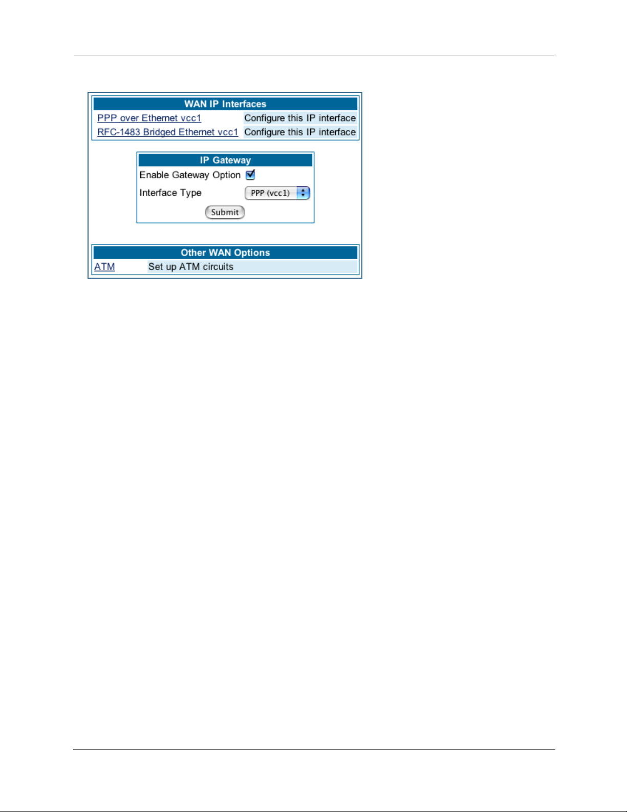
Once the VCCs have been configured,
the WAN IP Interfaces screen displays
the additional interface which you can
then configure as required.
75
Page 76

Administrator’s Handbook
ATM Traffic Shaping: You can prioritize delay-sensitive data by configuring the Quality of Service (QoS)
characteristics of the virtual circuit. Click the ATM Traffic Shaping link.
You can choose UBR (Unspecified Bit Rate), CBR (Constant Bit Rate), or VBR (Variable Bit Rate) from the
pull-down menu and set the Peak Cell Rate (PCR) in the editable field.
UBR (Unspecified Bit Rate) guarantees no minimum transmission rate. Cells are transmitted on a
“best effort” basis. However, there is a cap on the maximum transmission rate for UBR VCs. In a practical situation:
• UBR VCs should be transmitted at a priority lower than CBR.
• Bandwidth should be shared equally among UBR VCs.
UBR applications are non-real-time traffic such as IP data traffic.
CBR (Constant Bit Rate) guarantees a certain transmission rate (although the application may
underutilize this bandwidth). A Peak Cell Rate (PCR) characterizes CBR. CBR is most suited for real time
applications such as real time voice / video, although it can be used for other applications.
VBR (Variable Bit Rate) This class is characterized by:
• a Peak Cell Rate (PCR), which is a temporary burst, not a sustained rate, and
• a Sustained Cell Rate (SCR),
• a Burst Tolerance (BT), specified in terms of Maximum Burst Size (MBS). The MBS is the maximum
number of cells that can be transmitted at the peak cell rate and should be less than, or equal to the
Peak Cell Rate, which should be less than, or equal to the line rate.
VBR has two sub-classes:
a. VBR non-real-time (VBR-nrt): Typical applications are non-real-time traffic, such as IP data traffic. This
class yields a fair amount of Cell Delay Variation (CDV).
b. VBR real time (VBR-rt): Typical applications are real-time traffic, such as compressed voice over IP
and video conferencing. This class transmits cells with a more tightly bounded Cell Delay Variation. The
applications follow CBR.
☛ Note:
The difference between VBR-rt and VBR-nrt is the tolerated Cell Delay Variation range and the
provisioned Maximum Burst Size.
76
Page 77

Class PCR SCR MBS Transmit Priority Comments
UBR X N/A N/A Low PCR is a cap
CBR X N/A N/A High PCR is a guaranteed rate
VBR X X X High PCR > SCR.
SCR is a guaranteed rate.
PCR is a cap.
77
Page 78

Administrator’s Handbook
Link: Advanced
Selected Advanced options are discussed in the pages that follow. Many are self-explanatory or are dictated by your service provider.
The following are typical links under Configure -> Advanced (some models offer other links):
78
Page 79

Link: IP Static Routes
A static route identifies a manually configured pathway to a remote network. Unlike dynamic routes, which
are acquired and confirmed periodically from other routers, static routes do not time out. Consequently,
static routes are useful when working with PPP, since an intermittent PPP link may make maintenance of
dynamic routes problematic.
When you click the Static Routes link, the IP Static Routes page appears.
You can configure as many as 32 static IP routes for the Gateway. To add a static route, click the Add button.
The IP Static Route Entry page appears.
• Destination Network: Enter the IP address of the static route. It may not be 0.0.0.0.
• Netmask: Enter the subnet mask for the IP network at the other end of the static route. The subnet
mask associated with the destination network must represent the same network class (A, B, or C) or a
lower class (such as a class C subnet mask or class B network number) to be valid.
• Interface Type: Choose PPP (vcc1) – depending on the interface; typically vcc1 for DSL – or IP Address
from the pull-down menu to specify whether the static route is accessible through PPP or IP address.
• Gateway: Enter the IP address of the gateway for the static route. The default gateway must be located
on a network connected to your Motorola Netopia® Gateway configured inter face.
• Metric: Specifies the hop count for the static route. Enter a number from 1 to 15 to indicate the number
of routes (actual or best guess) a packet must traverse to reach the remote network. Some metric or a
value of 1 will be used to indicate:
• The remote network is one router away and the static route is the best way to
reach it.
• The remote network is more than one router away but the static route should not
be replaced by a dynamic route, even if the dynamic route is more ef ficient.
79
Page 80

Administrator’s Handbook
• RIP Advertise: From the pull-down menu, choose how the static route should be adver tised via RIP:
• Split Horizon: Do not advertise route if the gateway is on the same subnet.
• Always: Advertise route in all RIP messages.
• Never: Do not advertise route.
Click the Submit button. The Alert icon will appear, so that you can switch to the Save Changes
page, when you are finished.
Once you save your changes, you will be returned to the IP Static Routes entr y screen.
• You can continue to Add, Edit, or Delete Static Routes from this screen.
When you are finished, click the Alert icon , switch to the Save Changes page, and click the Save
Changes link.
80
Page 81

Link: IP Static ARP
Your Gateway maintains a dynamic Address Resolution Protocol (ARP) table to map IP addresses to Ethernet (MAC) addresses. It populates this ARP table dynamically, by retrieving IP address/MAC address pairs
only when it needs them. Optionally, you can define static ARP entries to map IP addresses to their corresponding Ethernet MAC addresses. Unlike dynamic ARP table entries, static ARP table entries do not time
out. The IP address cannot be 0.0.0.0. The Ethernet MAC address entr y is in nn-nn-nn-nn-nn-nn (hexadecimal) format.
81
Page 82

Administrator’s Handbook
Link: Pinholes
Pinholes allow you to transparently route selected types of network traffic, such as FTP requests or HTTP
(Web) connections, to a specific host behind the Gateway. Creating a pinhole allows access traffic originating from a remote connection (WAN) to be sent to the internal computer (LAN) that is specified in the Pinhole page.
Pinholes are common for applications like multiplayer online games. Refer to software manufacturer application documentation for specific traffic types and port numbers.
Configure Specific Pinholes. Planning for Your Pinholes. Determine if any of the service
applications that you want to provide on your LAN stations use TCP or UDP protocols. If an application does,
then you must configure a pinhole to implement port forwarding. This is accessed from the Advanced ->
Pinholes page.
Example: A LAN Requiring Three Pinholes . The procedure on the following pages describes
how you set up your NAT-enabled Motorola Netopia® Gateway to support three separate applications. This
requires passing three kinds of specific IP traffic through to your LAN.
Application 1
would like users on the Internet to have access to it. With NAT “On”, the only externally visible IP address
on your network is the Gateway’s WAN IP (supplied by your Service Provider). All traffic intended for that LAN
Web server must be directed to that IP address.
Application 2
the LAN users.
Application 3
cific LAN station to be dedicated to games.
A sample table to plan the desired pinholes is:
For this example, Internet protocols TCP and UDP must be passed through the NAT security feature and the
Gateway’s embedded Web (HTTP) port must be re-assigned by configuring new settings on the Internal
Servers page.
: You have a Web server located on your LAN behind your Motorola Netopia® Gateway and
: You want one of your LAN stations to act as the “central repositor y” for all email for all of
: One of your LAN stations is specially configured for game applications. You want this spe-
WAN Traffic Type Protocol Pinhole Name
Web TCP my-webserver 192.168.1.1
Email TCP my-mailserver 192.168.1.2
Games UDP my-games 192.168.1.3
LAN Internal IP
Address
82
Page 83
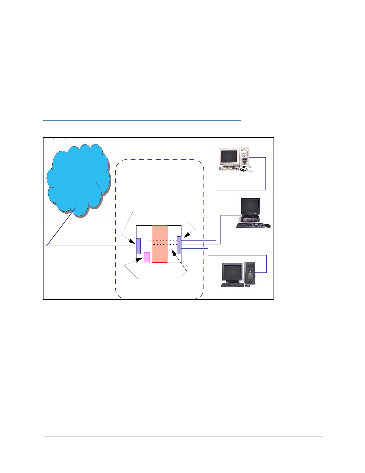
☛ TIPS for making Pinhole Entries:
1. If the port forwarding feature is required for Web services, ensure that the embedded Web
server’s port number is re-assigned PRIOR to any Pinhole data entry.
2. Enter data for one Pinhole at a time.
3. Use a unique name for each Pinhole. If you choose a duplicate name, it will overwrite the
previous information without warning.
A diagram of this LAN example is:
Gateway
Internet
WAN
Ethernet
Interface
210.219.41.20
LAN
Ethernet
Interface
my-webserver
192.168.1.1
NAT
Embedded
Web Server
210.219.41.20:8100
You can also use the LAN-side address of the Gateway, 192.168.1.x:8100 to access the web and
192.168.1.x:23 to access the telnet server.
NAT Pinholes
my-mailserver
192.168.1.2
my-games
192.168.1.3
83
Page 84

Administrator’s Handbook
Pinhole Configuration Procedure. Use the following steps:
1. From the Configure toolbar button -> Advanced link, select the Internal Servers link.
Since Port Forwarding is required for this example, the Motorola Netopia® embedded Web server is configured first.
☛ NOTE:
The two text boxes, Web (HTTP) Server Port and Telnet Server Port, on this page refer to
the port numbers of the Motorola Netopia® Gateway’s embedded administration ports.
To pass Web traffic through to your LAN station(s), select a Web (HTTP) Por t number that is greater than
1024. In this example, you choose 8100.
2. Type 8100 in the Web (HTTP) Server Port text box.
3. Click the Submit button.
4. Click Advanced. Select the Pinholes link to go to the Pinhole page.
5. Click Add. Type your specific data into the Pinhole Entries table of this page. Click Sub-
mit.
84
Page 85

6. Click on the Add or Edit more Pinholes link. Click the Add button. Add the next Pinhole.
Type the specific data for the second Pinhole.
7. Click on the Add or Edit more Pinholes link. Click the Add button. Add the next Pinhole.
Type the specific data for the third Pinhole.
☛ NOTE:
Note the following parameters for the “my-games” Pinhole:
1. The Protocol ID is UDP.
2. The external port is specified as a range.
3. The Internal port is specified as the lower range entry.
85
Page 86

Administrator’s Handbook
8. Click on the Add or Edit more Pinholes link. Review your entries to be sure they are cor-
rect.
9. Click the Alert icon.
10. Click the Save and Restart link to complete the entire Pinhole creation task and ensure
that the parameters are properly saved.
☛ NOTE:
REMEMBER: When you have re-assigned the port address for the embedded Web server, you
can still access this facility.
Use the Gateway’s WAN address plus the new port number.
In this example it would be
<WAN Gateway address>:<new port number> or, in this case, 210.219.41.20:8100
You can also use the LAN-side address of the Gateway, 192.168.1.x:8100 to access the web
and 192.168.1.x:23 to access the telnet server.
86
Page 87

Link: IPMaps
IPMaps supports one-to-one Network Address Translation (NAT) for IP addresses assigned to ser vers,
hosts, or specific computers on the LAN side of the Motorola Netopia® Gateway.
A single static or dynamic (DHCP) WAN IP address must be assigned to support other devices on the LAN.
These devices utilize Motorola Netopia®’s default NAT/PAT capabilities.
Configure the IPMaps Feature
FAQs for the IPMaps Feature
Before configuring an example of an IPMaps-enabled network, review these frequently asked questions.
What are IPMaps and how are they used? The IPMaps feature allows multiple static WAN IP
addresses to be assigned to the Motorola Netopia® Gateway.
Static WAN IP addresses are used to support specific services, like a web server, mail server, or DNS
server. This is accomplished by mapping a separate static WAN IP address to a specific internal LAN IP
address. All traffic arriving at the Gateway intended for the static IP address is transferred to the internal
device. All outbound traffic from the internal device appears to originate from the static IP address.
Locally hosted servers are supported by a public IP address while LAN users behind the NAT-enabled IP
address are protected.
IPMaps is compatible with the use of NAT, with either a statically assigned IP address or DHCP/PPP ser ved
IP address for the NAT table.
What types of servers are supported by IPMaps? IPMaps allows a Motorola Netopia® Gate-
way to support servers behind the Gateway, for example, web, mail, FTP, or DNS servers. VPN ser vers are
not supported at this time.
Can I use IPMaps with my PPPoE or PPPoA connection? Yes. IPMaps can be assigned to
the WAN interface provided they are on the same subnet. Service providers will need to ensure proper
routing to all IP addresses assigned to your WAN interface.
Will IPMaps allow IP addresses from different subnets to be assigned to my Gateway?
IPMap will support statically assigned WAN IP addresses from the same subnet.
WAN IP addresses from different subnets are not supported.
87
Page 88

Administrator’s Handbook
IPMaps Block Diagram
The following diagram shows the IPMaps principle in conjunction with existing Motorola Netopia® NAT operations:
Motorola Netopia® Gateway
Static IP Addresses
for IPMaps Applications
143.137.50.37
143.137.50.36
143.137.50.35
Static IP Addresses
or
DHCP/PPP Served IP Address
for Netopia’s default NAT/PAT
Capabilities
WAN Interface LAN Interface
IPMaps:
One-to-One
Multiple Address Mapping
NAT/PAT Table
143.137.50.37
143.137.50.36
143.137.50.35
LAN stations with WAN IP traffic
forwarded by Netopia’s IPMaps
LAN stations with WAN IP traffic
forwarded by Netopia’s NAT function.
...
192.168.1.1
192.168.1.2
192.168.1.3
...
192.168.1.n
192.168.1.1
192.168.1.2
192.168.1.3
.
.
.
192.168.1.n
88
Page 89

Link: Default Server
This feature allows you to:
• Direct your Gateway to forward all externally initiated IP traf fic (TCP and UDP protocols only) to a default
host on the LAN.
Enable it for certain situations:
– Where you cannot anticipate what port number or packet protocol an in-bound application might
use. For example, some network games select arbitrary port numbers when a connection is
opened.
– When you want all unsolicited traffic to go to a specific LAN host.
• Configure for IP Passthrough.
Configure a Default Server. This feature allows you to direct unsolicited or non-specific traf fic to a
designated LAN station. With NAT “On” in the Gateway, these packets normally would be discarded.
For instance, this could be application traffic where you don’t know (in advance) the port or protocol that
will be used. Some game applications fit this profile.
Use the following steps to setup a NAT default server to receive this information:
1. Select the Configure toolbar button, then Advanced, then the Default Server link.
2. From the pull-down menu, select Default-Server.
The NAT Server IP Address field appears.
3. Determine the IP address of the LAN computer you have chosen to receive the unex-
pected or unknown traffic.
Enter this address in the NAT Server IP Address field.
4. Click the Submit button.
5. Click the Alert button.
6. Click the Save and Restart link to confirm.
Typical Network Diagram. A typical network using the NAT Default Server looks like this:
89
Page 90

Administrator’s Handbook
Internet
Gateway
WAN
Ethernet
Interface
210.219.41.20
LAN
Ethernet
Interface
LAN STN #3
192.168.1.3
Embedded
Web Server
210.219.41.20
(Port 80 default)
NAT
NAT Default
Server
LAN STN #2
192.168.1.2
NAT protected
NAT Default Server
192.168.1.1
You can also use the LAN-side address of the Gateway, 192.168.1.x to access the web and telnet server.
NAT Combination Application. Motorola Netopia®’s NAT security feature allows you to configure a
sophisticated LAN layout that uses both the Pinhole and Default Server capabilities.
With this topology, you configure the embedded administration ports as a first task, followed by the Pinholes and, finally, the NAT Default Ser ver.
When using both NAT pinholes and NAT Default Ser ver the Gateway works with the following rules (in
sequence) to forward traffic from the Internet to the LAN:
1. If the packet is a response to an existing connection created by outbound traffic from a
LAN PC, forward to that station.
2. If not, check for a match with a pinhole configuration and, if one is found, forward the
packet according to the pinhole rule.
3. If there’s no pinhole, the packet is forwarded to the Default Server.
IP-Passthrough. Your Gateway offers an IP passthrough feature. The IP passthrough feature allows a
single PC on the LAN to have the Gateway’s public address assigned to it. It also provides PAT (NAPT) via
the same public IP address for all other hosts on the private LAN subnet. Using IP passthrough:
• The public WAN IP is used to provide IP address translation for private LAN computers.
• The public WAN IP is assigned and reused on a LAN computer.
90
Page 91

• DHCP address serving can automatically serve the WAN IP address to a LAN computer.
When DHCP is used for addressing the designated passthrough PC, the acquired or configured WAN
address is passed to DHCP, which will dynamically configure a single-servable-address subnet, and
reserve the address for the configured MAC address. This dynamic subnet configuration is based on the
local and remote WAN address and subnet mask. If the WAN interface does not have a suitable subnet
mask that is usable, for example when using PPP or PPPoE, the DHCP subnet configuration will default
to a class C subnet mask.
• If you want to manually assign the WAN address to a LAN PC, do not check the DHCP Enable checkbox.
• If you check the DHCP Enable checkbox, the screen expands.
The Host Hardware Address field displays. Here you enter the MAC address of the designated IPPassthrough computer.
• If this MAC address is not all zeroes, then it will use DHCP to set the LAN host's address to the (config-
ured or acquired) WAN IP address.
The MAC address must be six colon-delimited or dash-delimited sets of hex digits ('0' – 'FF').
• If you leave the MAC address as zeros then the first DHCP client will be assigned the WAN address.
Once configured, the passthrough host's DHCP leases will be shor tened to two minutes. This allows for
timely updates of the host's IP address, which will be a private IP address before the WAN connection is
established. After the WAN connection is established and has an address, the passthrough host can renew
its DHCP address binding to acquire the WAN IP address.
A restriction. Since both the Gateway and the passthrough host will use the same IP address, new ses-
sions that conflict with existing sessions will be rejected by the Gateway. For example, suppose you are a
teleworker using an IPSec tunnel from the Gateway and from the passthrough host. Both tunnels go to the
same remote endpoint, such as the VPN access concentrator at your employer’s office. In this case, the
first one to start the IPSec traffic will be allowed; the second one – since, from the WAN, it's indistinguishable – will fail.
91
Page 92

Administrator’s Handbook
Link: Differentiated Services
When you click the Differentiated Services link, the Differentiated Services configuration screen
appears.
Differentiated Services (Diffser v) allow your Gateway to make Quality of Ser vice (QoS) decisions about
what path Internet traffic, such as Voice over IP (VoIP), should travel across your network. For example, you
may want streaming video conferencing to use high quality, but more restrictive, connections, or, you might
want e-mail to use less restrictive, but less reliable, connections.
VDSL and Bonded ADSL models display this screen:
Most other models display this screen:
• To enable Differentiated Services, check the Enable checkbox.
• (Not displayed on VDSL and Bonded ADSL models) Enter a value from 60 to 100 (percent) in the Low-
High Priority Ratio field. The default is 92.
Differentiated Services uses the low-to-high priority queue ratio to regulate traffic flow. For example, to
provide the least possible latency and highest possible throughput for high priority traffic, you could set
the ratio to 100(%). This would cause the gateway to forward low priority data only after the high priority
queue is completely empty. In practice, you should set it to something less than 100%, since the low priority traffic might have to wait too long to be passed, and consequently be subject to time-outs.
Click the Submit button.
You can then define Custom Flows. If your applications do not provide Quality of Ser vice (QoS) control, Custom Flows allows you to define streams for some protocols, por t ranges, and between specific end point
addresses.
92
Page 93

• To define a custom flow, click the Add button.
The Custom Flow Entry screen appears.
• Name – Enter a name in this field to label the flow.
• Protocol – Select the protocol from the pull-down
menu: TCP (default), UDP, ICMP, or Other. “Other” is
appropriate for setting up flows on protocols with nonstandard port definitions. IPSEC and PPTP are common
examples.
• Numerical Protocol – If you select “Other” protocol,
this field appears for you to provide its actual protocol
number, with a range of 0 – 255.
• Direction – Choose Outbound (default), Inbound, or
Both from the pull-down menu.
• Start Port – For TCP or UDP protocols, you can optionally specify a range of ports. Enter the starting port here.
• End Port – Enter the ending port here.
• Inside IP Address/Netmask – For outbound flows,
specify an IP address/netmask on your LAN. For inbound
flows, this setting is ignored. This setting marks packets
from this LAN IP host/network based on the address and
netmask information. For outbound flows, the Inside IP
Address/Netmask is the source address. If you enter a
zero IP address (0.0.0.0), the IP address/netmask fields
will be ignored.
• Outside IP Address/Netmask – If you want traffic destined for and originating from a certain WAN IP
address to be controlled, enter the IP address and subnet mask here. If you leave the default all-zeroes,
the outside address check is ignored.
For outbound flows, the outside address is the destination IP address for traffic; for inbound packets,
the outside address is the source IP address.
Note:
When setting the Inside/Outside IP Address/Netmask settings, note that a netmask value can be used
to configure for a network rather than a single IP address.
93
Page 94

Administrator’s Handbook
• Quality of Service (QoS) – This is the Quality of Service setting for the flow, based on the TOS bit
information. Select Expedite, Assure, or Of f (default) from the pull-down menu. The following table outlines the TOS bit settings and behavior:
QoS Setting TOS Bit Value Behavior
Off TOS=000 This custom flow is disabled. You can activate it by selecting one
of the two settings below. This setting allows you to pre-define
flows without actually activating them.
Assure TOS=001 Use normal queuing and throughput rules, but do not drop pack-
ets if possible. Appropriate for applications with no guaranteed
delivery mechanism.
Expedite TOS=101 Use minimum delay. Appropriate for VoIP and video applications.
Network Control TOS=111 Use highest possible priority.
94
Page 95

Link: DNS
Your Ser vice Provider may maintain a Domain Name ser ver. If you have the information for the DNS ser vers, enter it on the DNS page. If your Gateway is configured to use DHCP to obtain its WAN IP address, the
DNS information is automatically obtained from that same DHCP Ser ver.
95
Page 96

Administrator’s Handbook
Link: DHCP Server
Your Gateway can provide network configuration information to computers on your LAN, using the Dynamic
Host Configuration Protocol (DHCP).
If you already have a DHCP server on your LAN, you should turn this ser vice off.
If you want the Gateway to provide this service, select Server from the Server Mode pull-down menu,
then configure the range of IP addresses that you would like the Gateway to hand out to your computers.
You can also specify the length of time the computers can use the configuration information; DHCP calls
this period the lease time.
Your Ser vice Provider may, for certain services, want to provide configuration from its DHCP servers to the
computers on your LANs. In this case, the Gateway will relay the DHCP requests from your computers to a
DHCP server in the Service Provider's network.
Select Relay-agent and enter the IP address of the Service Provider's DHCP server in the Server Address
field. This address is furnished by the Ser vice Provider.
☛ NOTE:
The relay-agent option only works when NAT is off and the Gateway is in router mode.
96
Page 97

Link: RADIUS Server
RADIUS servers allow external authentication of users by means of a remote authentication database. The
remote authentication database is maintained by a Remote Authentication Dial-In User Service (RADIUS)
server. In conjunction with Wireless User Authentication, you can use a RADIUS server database to authenticate users seeking access to the wireless services, as well as the authorized user list maintained locally
within the Gateway.
If you click the RADIUS link, the RADIUS Servers screen appears.
• RADIUS Server Addr/Name: The default RADIUS server name or IP address that you want to use.
• RADIUS Server Secret: The RADIUS secret key used by this server. The shared secret should have the
same characteristics as a normal password.
• RADIUS Server Port: The port on which the RADIUS server is listening, typically, the default 1812.
Click the Submit button.
You can also configure alternate RADIUS servers from the Wireless Configuration pages. See “Use RADIUS
Server” on page 65 for more information.
97
Page 98
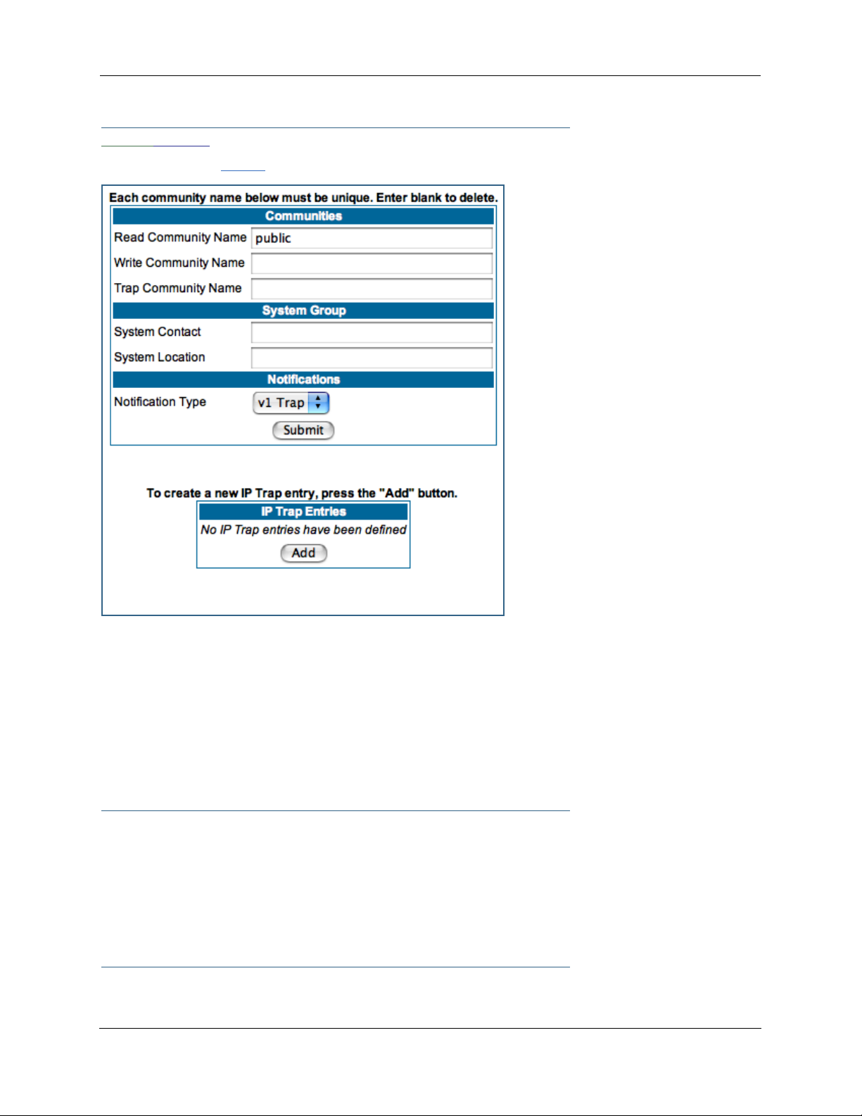
Administrator’s Handbook
Link: SNMP
When you click the SNMP link, the SNMP configuration page appears.
The Simple Network Management Protocol (SNMP) lets a network administrator monitor problems on a network by retrieving settings on remote network devices. The network administrator typically runs an SNMP
management station program on a local host to obtain information from an SNMP agent. In this case, the
Motorola Netopia® Gateway is an SNMP agent. Your Gateway suppor ts SNMP-V1, with the exception of
most sets (read-only and traps), and SNMP-V2. (For certain parts of the NPAV2TRAP.MIB – parameters under
resNatParams, resDslParams, resSecParams – set is suppor ted.)
You enter SNMP configuration information on this page. Your network administrator furnishes the SNMP
parameters.
☛ WARNING:
SNMP presents you with a security issue. The community facility of SNMP behaves
somewhat like a password. The community “public” is a well-known community name.
It could be used to examine the configuration of your Gateway by your service provider
or an uninvited reviewer. The information can be read from the Gateway.
If you are strongly concerned about security, you may leave the “public” community
blank.
98
Page 99
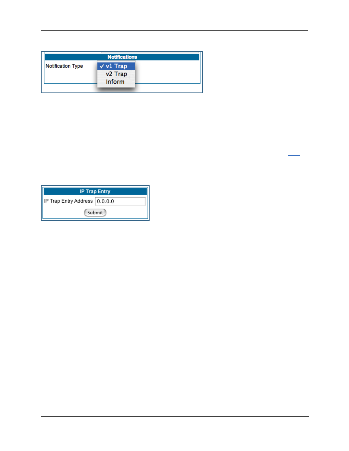
The Notification Type pull-down menu allows you to configure the type of SNMP notifications that will be
generated:
• v1 Trap – This selection will generate notifications containing an SNMPv1 Trap Protocol Data Unit (PDU)
• v2 Trap – This selection will generate notifications containing an SNMPv2 Trap PDU
• Inform – This selection will generate notifications containing an SNMPv2 InformRequest PDU.
To send SNMP traps, you must add IP addresses for each trap receiver you want to have. Click the Add
button.
The IP Trap Entry screen appears.
Enter an IP Trap Entry IP address. This is the destination for SNMP trap messages, the IP address of the
host acting as an SNMP console.
Click the Submit button. Click the Alert icon, and in the resulting page, click the Save and Restart link.
99
Page 100

Administrator’s Handbook
Link: IGMP (Internet Group Management Protocol)
Multicasting is a method for transmitting large amounts of information to many, but not all, computers
over an internet. One common use is to distribute real time voice, video, and data ser vices to the set of
computers which have joined a distributed conference. Other uses include updating the address books of
mobile computer users in the field, or sending out company newsletters to a distribution list.
Since a router should not be used as a passive forwarding device, Motorola Netopia® Gateways use a protocol for forwarding multicasting: Internet Group Management Protocol (IGMP).
Motorola Netopia® Gateways support IGMP Version 1, Version 2, or, beginning with Motorola Netopia®
Firmware Version 7.7, Version 3.
See the “Advanced” option in “LAN” on page 49 for more information.
IGMP “Snooping” is a feature of Ethernet layer 2 switches that “listens in” on the IGMP conversation
between computers and multicast routers. Through this process, it builds a database of where the multicast routers reside by noting IGMP general queries used in the querier selection process and by listening to
other router protocols.
From the host point of view, the snooping function listens at a port level for an IGMP repor t. The switch
then processes the IGMP repor t and starts forwarding the relevant multicast stream onto the host's por t.
When the switch receives an IGMP leave message, it processes the leave message, and if appropriate
stops the multicast stream to that particular port. Basically, customer IGMP messages although processed
by the switch are also sent to the multicast routers.
In order for IGMP snooping to function with IGMP Version 3, it must always track the full source filter state
of each host on each group, as was previously done with Version 2 only when Fast Leave support was
enabled.
IGMP Version 3 supports:
IGMP Source Filtering: the ability for group memberships to incorporate source address filtering. This allows
“Source-Specific Multicast” (SSM). By adding source filtering, a Gateway that proxies IGMP can more selectively join the specific multicast group for which there are interested LAN multicast receivers.
These features require no user configuration on the Gateway.
To configure IGMP options available in Motorola Netopia® Gateways, click the IGMP link.
100
 Loading...