

Page 1
User Manual
The Motorola Netopia® 2108-D9/N9
Gigabit Gateway
4 GigE ports, 802.11n Wi-Fi,
optional HPNA
Page 2

Safety Information
IMPORTANT SAFETY INSTRUCTIONS – POWER SUPPLY INSTALLATION. Connect the power supply
cord to the power jack on the Motorola Netopia
cal outlet.
CAUTION: Depending on the power supply provided with the product, either the direct plug-in power supply
blades, power supply cord plug or the appliance coupler serves as the mains power disconnect. It is important that the direct plug-in power supply, socket-outlet or appliance coupler be located so it is readily accessible.
ENGLISH
TELECOMMUNICATION INSTALLATION. When using your telephone equipment, basic safety precau-
tions should always be followed to reduce the risk of fire, electric shock and injury to persons, including
the following:
• Do not use this product near water, for example, near a bathtub, wash bowl, kitchen sink or laundry
tub, in a wet basement or near a swimming pool.
• Avoid using a telephone (other than a cordless type) during an electrical storm. There may be a remote
risk of electrical shock from lightning.
• Do not use the telephone to report a gas leak in the vicinity of the leak.
PRODUCT VENTILATION. The Motorola Netopia
home. Ambient temperatures around this product should not exceed 104°F (40°C). It should not be used in
locations exposed to outside heat radiation or trapping of its own heat. The product should have at least one
inch of clearance on all sides except the bottom when properly installed and should not be placed inside
tightly enclosed spaces unless proper ventilation is provided.
SAVE THESE INSTRUCTIONS
®
Gateway. Plug the power supply into an appropriate electri-
®
Gateway is intended for use in a consumer's
Motorola Part Number: 578175-001-00 revision b
Copyright © 2010 by Motorola, Inc.
All rights reserved. No part of this publication may be reproduced in any form or by any means or used to make any derivative
work (such as translation, transformation or adaptation) without written permission from Motorola, Inc. Motorola reserves the
right to revise this publication and to make changes in content from time to time without obligation on the part of Motorola to
provide notification of such revision or change. Motorola provides this guide without warranty of any kind, either implied or
expressed, including, but not limited to, the implied warranties of merchantability and fitness for a particular purpose. Motorola
may make improvements or changes in the product(s) described in this manual at any time. MOTOROLA and the Stylized M
Logo are registered in the US Patent & Trademark Office. Microsoft, Windows, Windows Me, and Windows NT are either
trademarks or registered trademarks of Microsoft Corporation in the U.S and/or other countries. Macintosh is a registered
trademark of Apple, Inc. Firefox is a registered trademark of the Mozilla Foundation. All other product or service names are the
property of their respective owners.
2
Page 3
1
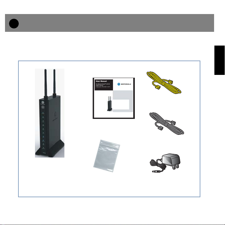
Checklist
Thank you for selecting the Motorola Netopia
guide will help you set up and configure your network.
Check your package contents. It should contain the items shown here:
®
2108-D9 or -N9 Gigabit Ethernet Gateway. This
1 Yellow RJ-45
Ethernet Cable
User Manual
1 Gray RJ-45
W
allmountin
Kit
g
Ethernet Cable
Motorola Gateway
Wallmounting Kit
(2 screws + 2 anchors)
If you don’t have everything, contact your supplier immediately.
Power
Supply
ENGLISH
3
Page 4

2
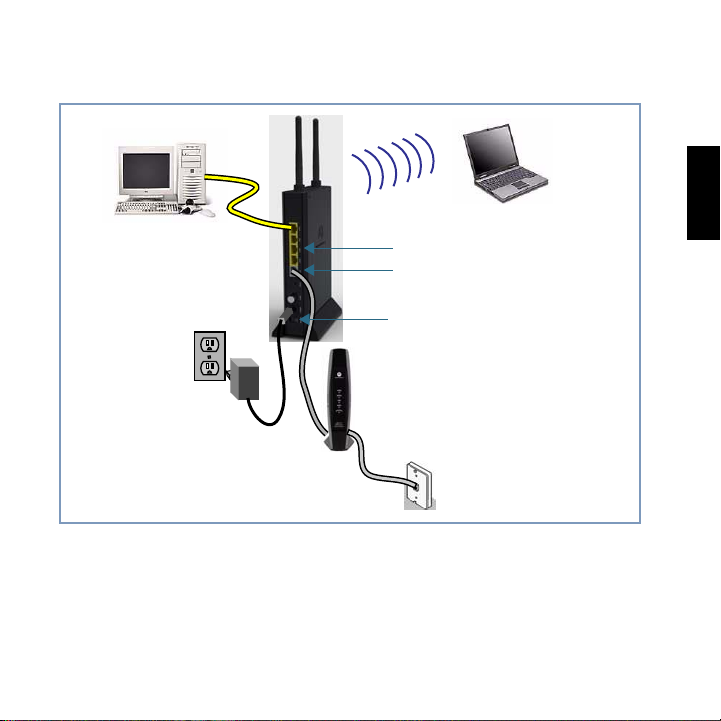
Connections
Select a suitable place on the network to install the Wireless Gateway.
1.
You can stand it up in its stand; lay it flat on a desktop; or mount it on a wall using the
included wall mounting kit hardware (see “Wall Mounting instructions (optional)” on
page 15).
2.
Use standard Cat5 Ethernet cables to connect PCs to the LAN ports on the
ENGLISH
rear of the Wireless Gateway.
One is supplied with your Gateway (yellow cable).
Connect the DSL or Cable modem to the gray WAN port on the Wireless Gate-
3.
way.
Use the cable supplied with your DSL/Cable modem. If the cable is missing, a standard
Cat5 Ethernet cable can be used.
Connect the supplied power adapter to the Wireless Gateway.
4.
Use only the power adapter provided. Using a different one may cause hardware damage. Turn the power ON with the ON/OFF Power Switch.
Check the LEDs:
5.
• The Power LED should be ON.
• The LAN LED(s) that have a cable connected should be ON when the connected device
is also on.
• The Wireless LED should be ON only when a wireless client is connected to this
Gateway.
• ( 2108-N9 HPNA model only ) The HPNA LED should be ON only when an HPNA
device(s) is connected via coaxial cable.
• The WAN LED should be ON when the WAN Port is connected via Cat5 cabling.
4
Page 5
• The Internet LED may initially be OFF. After proper configuration, it should come ON
When all of your connections are made, your network may look like this:
LAN
Port s
WAN Port
Power Switch
Rear View
DC Power
ENGLISH
5
Page 6
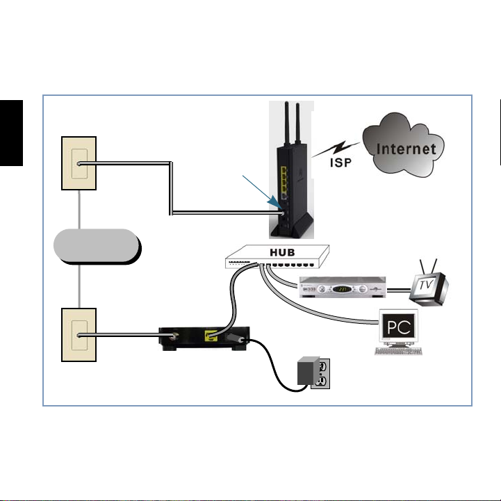
The figure below shows how to connect a Motorola 2108-N9 HPNA-enabled Gateway to
a home coaxial cable network using a Motorola HPNA Adaptor (purchased separately).
Follow the same steps to connect any Ethernet device such as a hub or printer to a coaxial cable network.
wall jack
ENGLISH
In-House
Coax Wiring
wall jack
Enable Wireless devices.
6.
In order to use the Access Point in the Wireless Gateway, other Wireless devices must
use the same SSID and Wireless Security settings as the Wireless Gateway.
Motorola HPNA Adapter
HPNA port
Ethernet
Motorola 2108-N9 Gateway
settop box
6
Page 7

The Wireless Gateway's default settings are as follows.
Setting Wireless Gateway
Default value: unique to your Gateway
SSID
Wireless
This may be changed on the Wireless screen, on the Wireless Gateway's main
menu.
Default Broadcast SSID: Enabled
Default Security: WPA2-PSK (20 bytes key, unique to your gateway)
Use the Wireless screen on the main menu to change this as required.
Ensure the Wireless Gateway and the other Wireless Stations are using the same settings.
• Use the Wireless setup screen to configure the Wireless Access Point in the Wireless
Gateway.
• Configure the Wireless stations (PCs) using your normal method for configuring their
Wireless interface.
• Wireless clients must also be set to use Infrastructure mode.
ENGLISH
7
Page 8
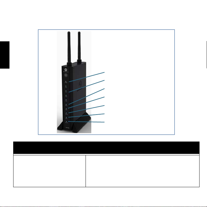
Front View
Power
Internet
WAN
LAN 1~4
HPNA (2108-N9 model only)
Wireless
WPS
When all of your connections are complete, the status LEDs on the front of your Motorola Neto-
®
pia
Gateway will light, in accordance with the following diagram:
ENGLISH
Power (Green, Red)
LED Definition
Off = Power Off
Green = Power On
Red = either power supply had become unstable or POST
failed
Blinking Red = Posting
Blinking Green = FW upgrading
8
Page 9

Internet
WAN
LAN 1~4
HPNA
(2108-N9 model only)
Wireless
WPS (Green, Yellow, Red)
LED Definition
Off = No IP connection
Solid Green = IP connection exists
Blinking Green = IP level traffic
Off = No connection
Solid Green = Connection
Blinking Green = traffic
Off = No connection
Solid Green = Connection
Blinking Green = traffic
Off = No connection
Solid Green = Connection
Blinking Green = traffic
Off = No connection
Solid Green = Connection
Blinking Green = traffic
Off = No action
Solid Green = WPS Success
Blinking Yellow = WPS in progress
Blikng Red = WPS Error or session overlap
ENGLISH
9
Page 10

3
Device Configuration
You can access the configuration pages at any time as follows:
1.
Run a Web browser, such as Firefox, Safari, or Microsoft Internet Explorer, and
enter
http://192.168.1.254
in the URL Address text box.
Press Return.
ENGLISH
When prompted, enter the Username and Password supplied by your ISP, if
2.
required.
Some ISPs do not require Username and Password. Refer to your ISP.
3.
Refer to the data from your ISP, and the table below, to ensure your choices
are correct.
Connection Type
Dynamic IP Address (DHCP) Usually, none.
Specified (Static) IP Address IP Address allocated to you, and related information.
PPPoE Login name and password.
Enter the information supplied by your Internet Service Provider.
10
Data Required
Page 11
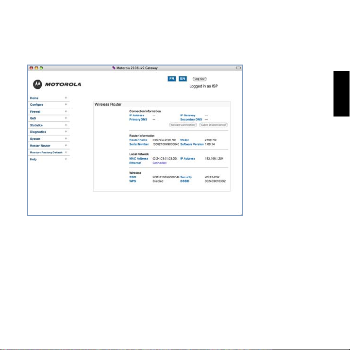
Check your connection.
4.
Click the HOME link at the top-left of your browser’s GUI display. View this page to verify
that an internet connection has been established. If the connection is not successful,
check the data you entered and the cabling connected to Gateway's Ethernet ports.
Congratulations! Your connection is up and running and you should be able to browse the
Internet by typing a URL address in your browser’s Address text box or by selecting any
of your favorite bookmarks.
ENGLISH
11
Page 12

a.
Client Configuration
Your Gateway serves Dynamically-assigned IP addresses by default. Be sure to configure
each computer connected to your Gateway to accept a Dynamically-assigned IP address,
commonly referred to as DHCP.
Microsoft Windows:
Step 1. Navigate to the TCP/IP Properties Control Panel.
ENGLISH
Windows 98, 2000, and ME versions follow a path like this:
Start menu -> Settings -> Control Panel -> Network (or Network and Dial-
up Connections -> Local Area Connection -> Properties ) -> TCP/IP
[your_network_card] or Internet Protocol [TCP/IP] -> Properties
b.
Windows XP follows a path like this:
Start menu -> Control Panel -> Network and Internet Connections ->
Network Connections -> Local Area Connection -> Properties -> Internet
Protocol [TCP/IP] -> Properties
Step 2. Select Obtain an IP address automatically.
Step 3. Select Obtain DNS server address automatically, if available.
Step 4. Remove any previously configured Gateways, if available.
Step 5. OK the settings. Restart if prompted.
12
Page 13

c. Windows Vista is set to obtain an IP address automatically by default. You may not
need to configure it at all.
To check, open the
IPv4)
. Click the
The
Internet Protocol Version 4
(TCP/IPv4) Properties
should appear as shown.
If not, select the radio buttons
shown above, and click the OK
button.
Networking
Properties
window
Control Panel and select
button.
Internet Protocol Version 4 (TCP/
ENGLISH
13
Page 14

Macintosh Mac OS 9 or Mac OS X:
Step 1. Access the TCP/IP or Network control panel.
a. Mac OS 9 follows a path like this:
Apple Menu -> Control Panels -> TCP/IP Control Panel
ENGLISH
b. Mac OS X follows a path like this:
Apple Menu -> System Preferences -> Network
Step 2. Select Built-in Ethernet
Step 3. Select Configure Using DHCP
Step 4. Close and Save, if prompted.
14
Page 15

Support
Answers to many frequently asked product-related questions, as well as full product documentation with advanced configuration instructions, are also available on-line at:
http://broadband.motorola.com/consumers/support/default.asp?supportSection=blank
Note the serial number (SN:) of your Gateway. It is located on the label on the bottom of the
Gateway below the model number. You will need the Gateway’s serial number if you need to
call for technical support.
Wall Mounting instructions (optional)
1. Hold a blank sheet of paper against the side of the Gateway with the mounting
slots.
2. With a pen or pencil, mark the position of the mounting slots.
Use this sheet of paper as a wall mounting template.
3. Place this template on the wall in the position the Gateway will be mounted.
It is recommended to mount the Gateway with the cable connections on the bottom.
4. Mark the mounting holes.
If mounting on wood, drill holes for the supplied screws.
If mounting on sheetrock, drill holes to accept the supplied sheetrock anchors.
5. Leave screws extended about 0.15 inches from the wall.
6. Hang the Gateway on the screws.
ENGLISH
15
Page 16

Recycling your Motorola Equipment
R
When you see this symbol on a
Motorola product, do not dispose of
the product with residential or commercial waste.
ENGLISH
available, call Motorola Customer Service for assistance. Please visit
http://www.motorola.com/recycle for instructions on recycling.
Please do not dispose of this
product with your residential
or commercial waste. Some
countries or regions, such as
the European Union, have set
up systems to collect and
recycle electrical and electronic waste items. Contact
your local authorities for information about practices established for your region.
If collection systems are not
ecyclage pour le respect
de l'environnement
Lorsque vous voyez ce symbole sur
un produit Motorola, ne le jetez pas
avec vos ordures ménagères ou vos
rebuts d'entreprise.
16
Recyclage de votre équipement Motorola
Veuillez ne pas jeter ce produit avec vos ordures
ménagères ou vos rebuts d'entreprise. Certains pays
ou certaines régions comme l'Union Européenne ont
mis en place des systèmes de collecte et de recyclage
des produits électriques et électroniques mis au rebut.
Veuillez contacter vos autorités locales pour vous
informer des pratiques instaurées dans votre region.
Si aucun système de collecte n'est disponible, veuillez
appeler le Service clientèle de Motorola qui vous
apportera son assistance.
Page 17

Page 18

 Loading...