

MOTOROLA
SEMICONDUCTOR
TECHNICAL DATA
1SMB5.0AT3
GENERAL DATA APPLICABLE TO ALL SERIES IN
THIS GROUP
Zener Transient Voltage Suppressors
The SMB series is designed to protect voltage sensitive components from high voltage,
high energy transients. They have excellent clamping capability , high surge capability, low
zener impedance and fast response time. The SMB series is supplied in Motorola’s
exclusive, cost-effective, highly reliable Surmetic package and is ideally suited for use in
communication systems, numerical controls, process controls, medical equipment,
business machines, power supplies and many other industrial/consumer applications.
Specification Features:
• Standard Zener Breakdown Voltage Range — 6.8 to 200 V
• Stand-off Voltage Range — 5 to 170 V
• Peak Power — 600 Watts @ 1 ms
• Maximum Clamp Voltage @ Peak Pulse Current
• Low Leakage < 5 µA Above 10 V
• UL Recognition
• Response Time Typically < 1 ns
Mechanical Characteristics:
CASE: Void-free, transfer-molded, thermosetting plastic
FINISH: All external surfaces are corrosion resistant and leads are readily solderable
POLARITY: Cathode indicated by molded polarity notch. When operated in zener mode,
will be positive with respect to anode
MOUNTING POSITION: Any
LEADS: Modified L-Bend providing more contact area to bond pad
MAXIMUM CASE TEMPERATURE FOR SOLDERING PURPOSES: 260°C for 10 seconds
WAFER FAB LOCATION: Phoenix, Arizona
ASSEMBLY/TEST LOCATION: Seremban, Malaysia
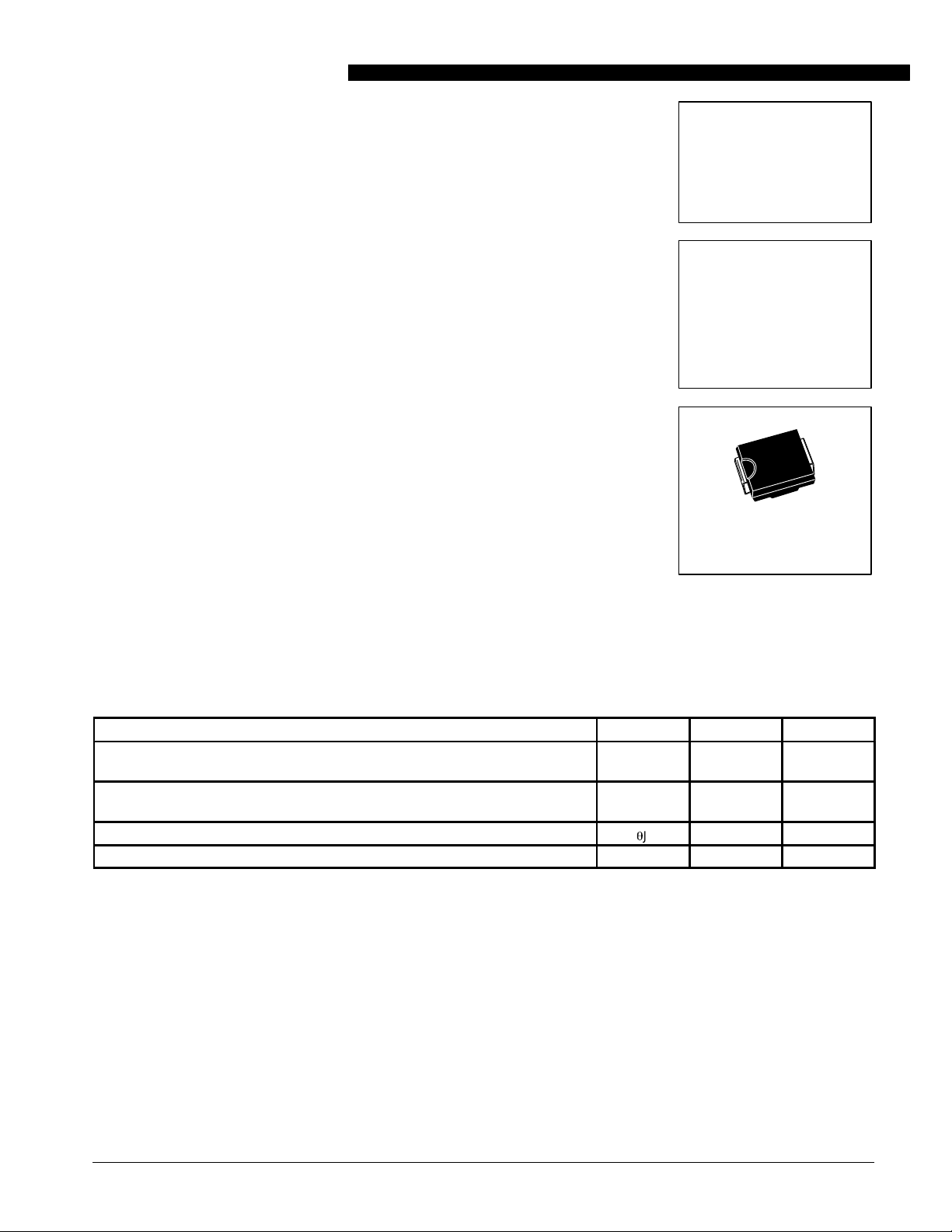
SERIES
600 WATT
PEAK POWER
PLASTIC SURFACE MOUNT
ZENER OVERVOLTAGE
TRANSIENT
SUPPRESSORS
6.8–200 VOL TS
600 WATT PEAK POWER
CASE 403A
PLASTIC
MAXIMUM RATINGS
Rating Symbol Value Unit
Peak Power Dissipation (1)
@ TL ≤ 25°C
Forward Surge Current (2)
@ TA = 25°C
Thermal Resistance from Junction to Lead (typical)
Operating and Storage Temperature Range TJ, T
NOTES: 1. Nonrepetitive current pulse per Figure 2 and derated above TA = 25°C per Figure 3.
NOTES: 2. 1/2 sine wave (or equivalent square wave), PW = 8.3 ms, duty cycle = 4 pulses per minute maximum.
REV 1
P
I
FSM
R
q
PK
JL
stg
600 Watts
100 Amps
25 °C/W
– 65 to +150 °C
Motorola TVS/Zener Device Data
600 Watt Peak Power Data Sheet
5-1

GENERAL DATA — 600 WATT PEAK POWER
(
)
Stand-Off Voltage
Clamping Voltage
(See Figure 2)
@ V
R
ELECTRICAL CHARACTERISTICS
Reverse
Stand-Off Volta
V
Device
{{
1SMB5.0AT3
1SMB6.0AT3
1SMB6.5AT3
1SMB7.0AT3
1SMB7.5AT3
1SMB8.0AT3
1SMB8.5AT3
1SMB9.0AT3
1SMB10AT3
1SMB11AT3
1SMB12AT3
1SMB13AT3
1SMB14AT3
1SMB15AT3
1SMB16AT3
1SMB17AT3
1SMB18AT3
1SMB20AT3
1SMB22A T3
1SMB24AT3
1SMB26AT3
1SMB28AT3
1SMB30AT3
1SMB33AT3
1SMB36AT3
1SMB40AT3
1SMB43AT3
1SMB45AT3
1SMB48AT3
1SMB51AT3
1SMB54AT3
1SMB58A T3
1SMB60AT3
1SMB64AT3
1SMB70AT3
1SMB75AT3
1SMB78AT3
1SMB85AT3
1SMB90AT3
1SMB100AT3
1SMB110AT3
1SMB120AT3
1SMB130AT3
1SMB150AT3
1SMB160AT3
1SMB170AT3
Note 1: A transient suppressor is normally selected according to the reverse ”Stand Off Voltage” (VR) which should be equal to or greater than the DC or continuous peak operating
voltage level.
* * VBR measured at pulse test current IT at an ambient temperaure of 25°C.
{{
Surge current waveform per Figure 2 and derate per Figure 3 of the General Data — 600 Watt at the beginning of this group.
{{
T3 suffix designates tape and reel of 2500 units.
ABBREVIATIONS AND SYMBOLS
V
R
V
(BR)min
V
C
Stand Off Voltage. Applied reverse voltage to assure a
non-conductive condition (See Note 1).
This is the minimum breakdown voltage the device will
exhibit and is used to assure that conduction does not
occur prior to this voltage level at 25°C.
Maximum Clamping Voltage. The maximum peak voltage appearing across the transient suppressor when
R
Volts (1)
5.0
6.0
6.5
7.0
7.5
8.0
8.5
9.0
10
11
12
13
14
15
16
17
18
20
22
24
26
28
30
33
36
40
43
45
48
51
54
58
60
64
70
75
78
85
90
100
110
120
130
150
160
170
(TA = 25°C unless otherwise noted).
Breakdown Voltage*
e
Volts
Min mA
6.40
6.67
7.22
7.78
8.33
8.89
9.44
10.0
11.1
12.2
13.3
14.4
15.6
16.7
17.8
18.9
20.0
22.2
24.4
26.7
28.9
31.1
33.3
36.7
40.0
44.4
47.8
50.0
53.3
56.7
60.0
64.4
66.7
71.1
77.8
83.3
86.7
94.4
100
111
122
133
144
167
178
189
VBR @ I
T
10
10
10
10
1.0
1.0
1.0
1.0
1.0
1.0
1.0
1.0
1.0
1.0
1.0
1.0
1.0
1.0
1.0
1.0
1.0
1.0
1.0
1.0
1.0
1.0
1.0
1.0
1.0
1.0
1.0
1.0
1.0
1.0
1.0
1.0
1.0
1.0
1.0
1.0
1.0
1.0
1.0
1.0
1.0
1.0
Maximum
Clamin Volta
VC @ I
pp
Volts
9.2
10.3
11.2
12.0
12.9
13.6
14.4
15.4
17.0
18.2
19.9
21.5
23.2
24.4
26.0
27.6
29.2
32.4
35.5
38.9
42.1
45.4
48.4
53.3
58.1
64.5
69.4
72.7
77.4
82.4
87.1
93.6
96.8
103
113
121
126
137
146
162
177
193
209
243
259
275
I
PP
P
P
I
R
Peak
Pulse Current
See Figure 2
e
Ipp{
Amps
65.2
58.3
53.6
50.0
46.5
44.1
41.7
39.0
35.3
33.0
30.2
27.9
25.8
24.0
23.1
21.7
20.5
18.5
16.9
15.4
14.2
13.2
12.4
11.3
10.3
9.3
8.6
8.3
7.7
7.3
6.9
6.4
6.2
5.8
5.3
4.9
4.7
4.4
4.1
3.7
3.4
3.1
2.9
2.5
2.3
2.2
subjected to the peak pusle current in a one millisecond
time interval. The peak pulse voltages are the combination of voltage rise due to both the series resistance and
thermal rise.
Peak Pulse Current — See Figure 2
Peak Pulse Power
Reverse Leakage
Maximum
Reverse Leakage
@ V
I
R
µA
800
800
500
200
100
50
10
5.0
5.0
5.0
5.0
5.0
5.0
5.0
5.0
5.0
5.0
5.0
5.0
5.0
5.0
5.0
5.0
5.0
5.0
5.0
5.0
5.0
5.0
5.0
5.0
5.0
5.0
5.0
5.0
5.0
5.0
5.0
5.0
5.0
5.0
5.0
5.0
5.0
5.0
5.0
Device
Marking
KE
KG
KK
KM
KP
KR
KT
KV
KX
KZ
LE
LG
LK
LM
LP
LR
LT
LV
LX
LZ
ME
MG
MK
MM
MP
MR
MT
MV
MX
MZ
NE
NG
NK
NM
NP
NR
NT
NV
NX
NZ
PE
PG
PK
PM
PP
PR
600 Watt Peak Power Data Sheet
5-2
Motorola TVS/Zener Device Data

GENERAL DATA — 600 WATT PEAK POWER
100
10
P
1
P , PEAK POWER (kW)
0.1
µ
s1
µ
0.1
160
°
140
= 25 C
A
120
100
80
60
s10
NONREPETITIVE
PULSE WAVEFORM
SHOWN IN FIGURE 2
µ
s 100
tP, PULSE WIDTH
µ
s
Figure 1. Pulse Rating
Curve
1 ms 10 ms
PULSE WIDTH (tP) IS DEFINED
t
r
100
VALUE (%)
50
0
PEAK VALUE – I
HALF VALUE –
t
P
01234
AS THAT POINT WHERE THE PEAK
CURRENT DECAYS TO 50%
OF I
.
RSM
tr≤
RSM
10 µs
I
RSM
t, TIME (ms)
2
Figure 2. Pulse Waveform
TYPICAL PROTECTION CIRCUIT
Z
in
V
in
LOAD
V
L
40
PEAK PULSE DERATING IN % OF
20
PEAK POWER OR CURRENT @ T
0
0 25 50 75 100 125 150
TA, AMBIENT TEMPERATURE (
°
C)
Figure 3. Pulse Derating Curve
APPLICATION NOTES
RESPONSE TIME
In most applications, the transient suppressor device is
placed in parallel with the equipment or component to be
protected. In this situation, there is a time delay associated
with the capacitance of the device and an overshoot condition
associated with the inductance of the device and the
inductance of the connection method. The capacitive effect is
of minor importance in the parallel protection scheme because
it only produces a time delay in the transition from the
operating voltage to the clamp voltage as shown in Figure 4.
The inductive effects in the device are due to actual turn-on
time (time required for the device to go from zero current to full
current) and lead inductance. This inductive effect produces
an overshoot in the voltage across the equipment or
component being protected as shown in Figure 5. Minimizing
this overshoot is very important in the application, since the
main purpose for adding a transient suppressor is to clamp
voltage spikes. The SMB series have a very good response
time, typically < 1 ns and negligible inductance. However,
external inductive effects could produce unacceptable overshoot. Proper circuit layout, minimum lead lengths and placing
the suppressor device as close as possible to the equipment
or components to be protected will minimize this overshoot.
Some input impedance represented by Zin is essential to
prevent overstress of the protection device. This impedance
should be as high as possible, without restricting the circuit
operation.
DUTY CYCLE DERATING
The data of Figure 1 applies for non-repetitive conditions
and at a lead temperature of 25°C. If the duty cycle increases,
the peak power must be reduced as indicated by the curves of
Figure 6. Average power must be derated as the lead or
ambient temperature rises above 25°C. The average power
derating curve normally given on data sheets may be
normalized and used for this purpose.
At first glance the derating curves of Figure 6 appear to be in
error as the 10 ms pulse has a higher derating factor than the
10 µs pulse. However, when the derating factor for a given
pulse of Figure 6 is multiplied by the peak power value of
Figure 1 for the same pulse, the results follow the expected
trend.
Motorola TVS/Zener Device Data
600 Watt Peak Power Data Sheet
5-3

GENERAL DATA — 600 WATT PEAK POWER
V
V
in
t
d
tD = TIME DELAY DUE T O CAPACITIVE EFFECT
Figure 4. Figure 5.
DERATING FACTOR
OVERSHOOT DUE TO
Vin (TRANSIENT)
V
L
t t
1
0.7
0.5
0.3
0.2
0.1
0.07
0.05
0.03
0.02
0.01
0.1 0.2 0.5 2 5 10 501 20 100
D, DUTY CYCLE (%)
V
INDUCTIVE EFFECTS
PULSE WIDTH
10 ms
1 ms
100 µs
10 µs
Vin (TRANSIENT)
V
L
Figure 6. T ypical Derating Factor for Duty Cycle
UL RECOGNITION
The entire series has
for the classification of protectors (QVGV2) under the UL
standard for safety 497B and File #1 161 10. Many competitors
only have one or two devices recognized or have recognition
in a non-protective category. Some competitors have no
recognition at all. With the UL497B recognition, our parts
successfully passed several tests including Strike Voltage
Underwriters Laboratory Recognition
Breakdown test, Endurance Conditioning, Temperature test,
Dielectric Voltage-Withstand test, Discharge test and several
more.
Whereas, some competitors have only passed a flammability test for the package material, we have been recognized for
much more to be included in their Protector category .
600 Watt Peak Power Data Sheet
5-4
Motorola TVS/Zener Device Data

GENERAL DATA — 600 WATT PEAK POWER
Transient Voltage Suppressors — Surface Mounted
600 Watt Peak Power
0.089
2.261
S
A
D
B
KP
J
H
CASE 403A
PLASTIC
(Refer to Section 10 for Surface Mount, Thermal Data and Footprint Information.)
MULTIPLE PACKAGE QUANTITY (MPQ)
REQUIREMENTS
Package Option
Tape and Reel 2.5K
(Refer to Section 10 for more information on Packaging Specifications.)
Type No. Suffix
T3 (13 inch reel)
MPQ (Units)
0.108
2.743
0.085
2.159
inches
mm
SMB Footprint
NOTES:
1. DIMENSIONING AND TOLERANCING PER ANSI
C
Y14.5M, 1982.
2. CONTROLLING DIMENSION: INCH.
3. D DIMENSION SHALL BE MEASURED WITHIN
DIMENSION P.
INCHES MILLIMETERS
MIN MINMAX MAX
DIM
A
0.160
B
0.130
C
0.075
D
0.077
H
0.0020
J
0.006
K
0.030
P
S
0.205
0.180
0.150
0.095
0.083
0.0060
0.012
0.050
0.220
4.06
3.30
1.90
1.96
0.051
0.15
0.76
0.51 REF0.020 REF
5.21
4.57
3.81
2.41
2.11
0.152
0.30
1.27
5.59
Motorola TVS/Zener Device Data
600 Watt Peak Power Data Sheet
5-5
 Loading...