

Motorline professional TEC100 Installation Manual
V3.0
REV. 01/2019
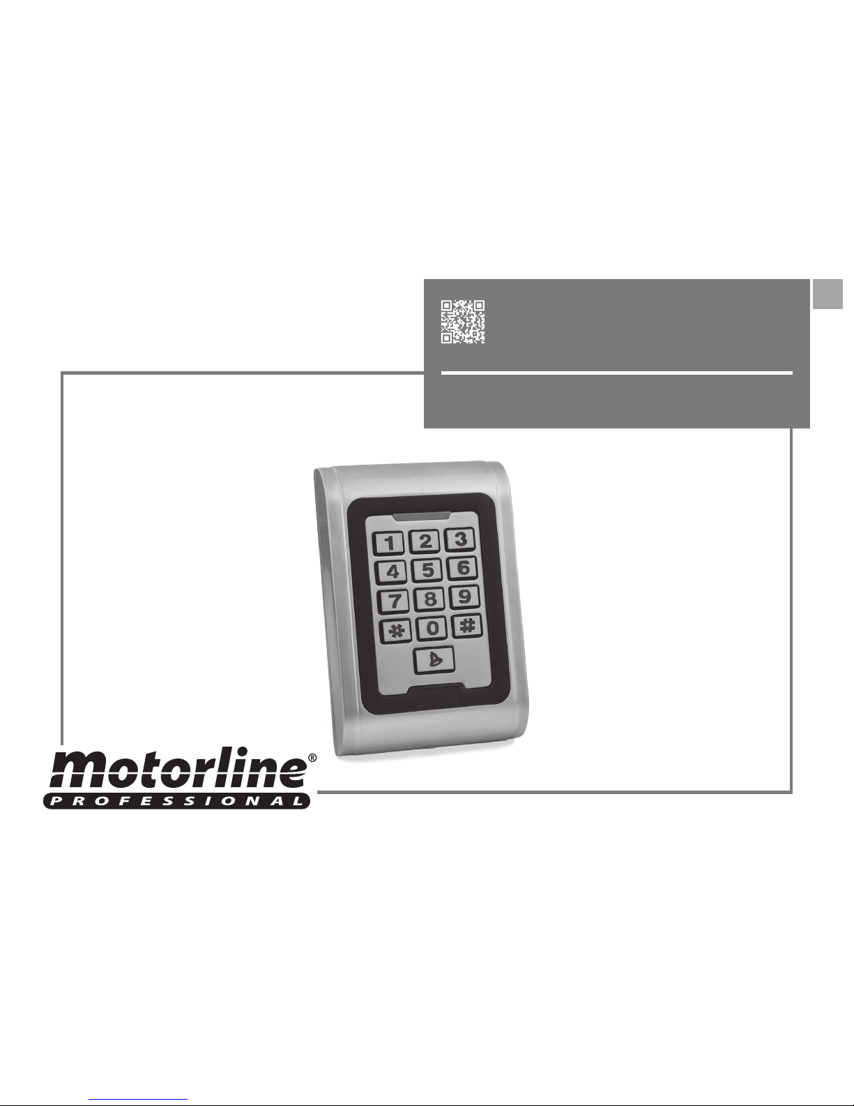
TEC100
EN
USER/INSTALLER MANUAL
A B
1B
2B
3A
4A
4B
9B
9A
6A
6B
6B
7A
10
2B
ENEN
STANDARDS TO FOLLOW
PRODUCT PROFILE
PRODUCT INSTALLATION
QUICK REFERENCE PROGRAMMING GUIDE
USER SETTINGS
LEAD WIRE DESCRIPTION
SOUNDS AND LIGHTS
DOOR SETTINGS
RESET TO FACTORY DEFAULT
ANTI TAMPER ALARM
ACCESS CONTROL THROUGH CODE (MCA)
CABLING DIAGRAM
. SAFETY INSTRUCTIONS
. PRODUCT
. INSTALLATION
. PROGRAMMING
. DETAILED PROGRAMMING GUIDE
. CABLING
. ACOUSTO-OPTIC INSTRUCTIONS
. CONTENT . SAFETY INSTRUCTIONS
INDEX STANDARDS TO FOLLOW
TECHNICAL PARAMETERS
ATTENTION:
This product is certified in accordance with European Community
(EC) safety standards.
This product complies with Directive 2011/65/EU of the European
Parliament and of the Council, of 8 June 2011, on the restriction of
the use of certain hazardous substances in electrical and electronic
equipment.
(Applicable in countries with recycling systems).
This marking on the product or literature indicates that the product
and electronic accessories (eg. Charger, USB cable, electronic material,
controls, etc.) should not be disposed of as other household waste at
the end of its useful life. To avoid possible harm to the environment
or human health resulting from the uncontrolled disposal of waste,
separate these items from other types of waste and recycle them
responsibly to promote the sustainable reuse of material resources.
Home users should contact the dealer where they purchased this
product or the National Environment Agency for details on where and
how they can take these items for environmentally safe recycling.
Business users should contact their vendor and check the terms and
conditions of the purchase agreement. This product and its electronic
accessories should not be mixed with other commercial waste.
This marking indicates that the product and electronic accessories
(eg. charger, USB cable, electronic material, controls, etc.) are
susceptible to electric shock by direct or indirect contact with
electricity. Be cautious when handling the product and observe all
safety procedures in this manual.
A B
ENEN
. SAFETY INSTRUCTIONS . PRODUCT
STANDARDS TO FOLLOW PRODUCT PROFILE
TECHNICAL PARAMETERS
The unit is single door multifunction standalone access controller or a Wiegand output keypad
or card reader. It is suitable for mounting either indoor or outdoor in harsh environments. It
is housed in a strong, sturdy and vandal proof Zinc Alloy electroplated case which is available
in either a bright silver or matt silver finish. The electronics are fully potted so the unit is
waterproof and conforms to IP68. This unit supports up to 2000 users in either a Card, 4 digit
PIN, or a Card + PIN option. The inbuilt card reader supports 125KHZ EM cards,13.56MHz Mifare
cards. The unit has many extra features including lock output current short circuit protection,
Wiegand output , and a backlit keypad. These features make the unit an ideal choice for
door access not only for small shops and domestic households but also for commercial and
industrial applications such as factories, warehouses, laboratories, banks and prisons.
• Waterproof, conforms to IP68
• Strong Zinc Alloy Electroplated antivandal case
• Full programming from the keypad
• 2000 uses, supports Card, PIN, Card + PIN
• Can be used as a stand alone keypad
• Backlight keys
• Wiegand 26 input for connection to
external reader
• Wiegand 26 output for connection to a
controller
• Adjustable Door Output time, Alarm time,
Door Open time
• Very low power consumption (30mA)
• Fast operating speed, <20ms with 2000
users
• Lock output current short circuit
protection
• Easy to install and program
• Built in light dependent resistor (LDR) for
anti tamper
• Built in buzzer
• Red, Yellow and Green LEDS display the
working status
• Work Voltage ac&dc 9-28V
• Static Current <30mA
• Reading Range 3-8cm
• Capacity 2000 users
• Ambient Temperature -25~55C
• Ambient Humidity 10% ~ 90%
• Electricity lock output <3A
• Alarm output <20A
• Output short circuit protection time <100S
• Open time 0 ~ 99 seconds (adjustable)
• It is important for your safety that these instructions are followed.
• Keep these instructions in a safe place for future reference.
• The ELECTROCELOS S.A. is not responsible for the improper use of the product,
or other use than that for which it was designed.
• The ELECTROCELOS S.A. is not responsible if safety standards were not taken
into account when installing the equipment, or for any deformation that may
occur.
• The ELECTROCELOS S.A. is not responsible for insecurity and malfunction of the
product when used with components that were not sold by the them.
• This product was designed and manufactured strictly for the use indicated in
this manual.
• Any other use not expressly indicated may damage the product and/or can
cause physical and property damages, and will void the warranty.
• Do not make any changes to the automation components and/or their
accessories.
• The customer shall not, under any circumstances, attempt to repair or tune the
automatism. Must call qualified technician only.
• The installer must have certified professional knowledge at the level of electronic.
He should also be able to perform electrical connections in compliance with all
applicable regulations.
• The installer should inform the customer how to handle the product in an
emergency and provide him the manual.
• This device can be used by children 8 year old or older and persons whose
physical, sensory or mental capacities are reduced, or by persons without
experience or knowledge if they have received supervision or instructions on
the use of the device in a safe manner and understood the hazards involved.
Children should not play with the device. Cleaning and maintenance by the user
must not be carried out by unsupervised children.
• Automatism powered by very low safety voltage, with electronic board/control
board/control unit.
• Before installing, the installer must verify that the temperature range indicated
on the automatism is appropriate to the location of the installation.
• In order to protect the electrical cables against mechanical stress, you should
use conduit for the electrical wires, essentially on the power cable.
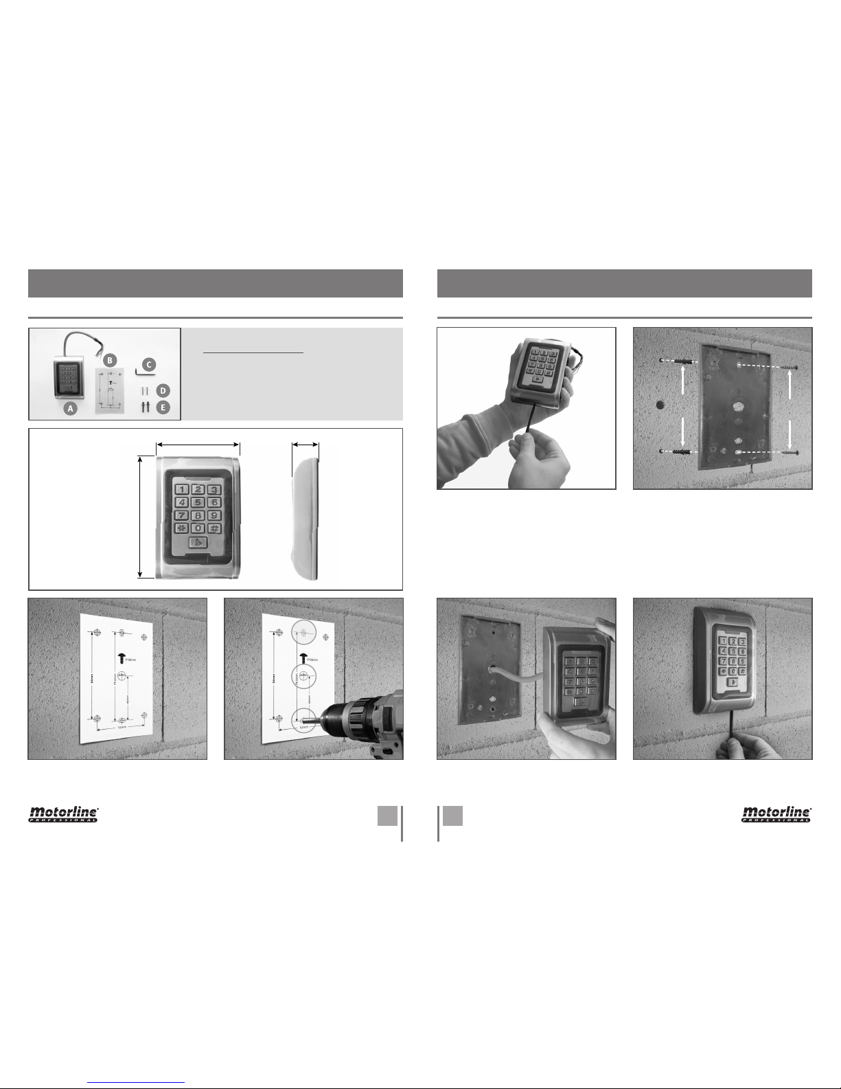
A B
88mm
27mm
122mm
ENEN
. INSTALLATION
PRODUCT INSTALLATION PRODUCT INSTALLATION
. INSTALLATION
1 • Apply the drilling diagram (B) to the
desired installation place.
3 • Using the hex key (C), loosen the screw in
totality and remove the back cover.
5 • Insert the cable into the hole.2 • Make the holes:
F - TEC100 fixing holes;
G - hole to pass the cable.
4 • Insert the bushings, place the back cover
and tighten totally the screws.
BUSHING
F
G
F
SCREW
6 • Attach the body of the TEC100 to the
back cover, insert the screw and tighten
completely.
A • TEC100
B • Drilling diagram
C • Hex key
D • Screws
E • Bushings
Caption
 Loading...