

Motorline professional ROSSO EVO User Manual

v4.0
REV. 05/2018
EN
USER'S AND INSTALLER'S MANUAL
ROSSO EVO
2A 2B
2B
4A
4B
7A
10A
14A
15
16
18
5A
7B
10B
14B
17
5B
9
13B
14B
5B
6A
6A
6B
ENEN
STANDARDS TO FOLLOW
INSIDE THE PACKAGE
TECHNICAL SPECIFICATIONS
ENGINE’S FIXATION IN THE PIPELINE
LEGEND
STOPPER AT THE OPENING
CONNECTING ENGINE TO 24V BATTERY
CONTROL BOARD ERROR MAP
ROSSO EVO CENTRAL
MANUAL BRAKE RELEASE
THE AUTOMATISM INSTALLATION
MENU FUNCTIONS
STRETCH RAIL CHAIN
INSTRUCTIONS FOR CONSUMERS | TECHNICAL PERSONNEL
REMOVE UPPER COVER
INSTALLATION MAP
PROGRAMMING TRANSMITTERS
MAINTENANCE
REPLACE UPPER COVER
CHANGING COURTESY LEDS
CHANGING FUSE
PRE-INSTALLATION INFORMATION
01. SAFETY INSTRUCTIONS
02. PACKAGE
03. THE AUTOMATISM
04. INSTALLATION
05. PROGRAMMING
06. POST-INSTALLATION
07. DIAGNOSIS
08. TROUBLESHOOTING
09. CENTRAL CONNECTIONS
INDEX
STANDARDS TO FOLLOW
00. CONTENT 01. SAFETY INSTRUCTIONS
This product is certified in accordance with European
Community (EC) safety standards.
This product complies with Directive 2011/65/EU of the
European Parliament and of the Council, of 8 June 2011, on
the restriction of the use of certain hazardous substances in
electrical and electronic equipment.
(Applicable in countries with recycling systems).
This marking on the product or literature indicates that the
product and electronic accessories (eg. Charger, USB cable,
electronic material, controls, etc.) should not be disposed of
as other household waste at the end of its useful life. To avoid
possible harm to the environment or human health resulting
from the uncontrolled disposal of waste, separate these items
from other types of waste and recycle them responsibly to
promote the sustainable reuse of material resources. Home
users should contact the dealer where they purchased this
product or the National Environment Agency for details on
where and how they can take these items for environmentally
safe recycling. Business users should contact their vendor and
check the terms and conditions of the purchase agreement.
This product and its electronic accessories should not be
mixed with other commercial waste.
This marking indicates that the product and electronic accessories
(eg. charger, USB cable, electronic material, controls, etc.) are
susceptible to electric shock by direct or indirect contact with
electricity. Be cautious when handling the product and observe
all safety procedures in this manual.
3A 3B
ENEN
STANDARDS TO FOLLOWSTANDARDS TO FOLLOW
01. SAFETY INSTRUCTIONS01. SAFETY INSTRUCTIONS
• Automatism powered by very low safety voltage, with electronic board /
control board / control unit.
• Before installing, the installer must verify that the temperature range
indicated on the automatism is appropriate to the location of the installation.
• Before installing, the installer must verify that the equipment to be
automated is in good mechanical condition, correctly balanced and opens
and closes properly.
• If the automation is to be installed at a level higher than 2,5 m above
ground level or other level of access, , should be followed the minimum
safety and health requirements for the use of work equipment workers
at work in Directive 2009/104/EC of the European Parliament and of the
Council of 16th September of 2009.
• In the case of the equipment where the automation will be installed, have
a pedestrian door, be aware that it must be closed when the automation is
activated.
• After installation, make sure that the mechanism is properly adjusted and
that the protection system and any manual unlocker works correctly.
• When programming the control unit, pay particular attention to touching
only the location intended for that purpose. Failure to do so may result in
electric shock.
• Replacement of the power cable in the automation can only be carried out
by specialized technicians or by the manufacturer.
It is important for your safety that these instructions are followed.
• Keep these instructions in a safe place for future reference.
• The ELECTROCELOS S.A. is not responsible for the improper use of the
product, or other use than that for which it was designed.
• The ELECTROCELOS S.A. is not responsible if safety standards were not
taken into account when installing the equipment, or for any deformation
that may occur.
• The ELECTROCELOS S.A. is not responsible for insecurity and malfunction
of the product when used with components that were not sold by the them.
• This product was designed and manufactured strictly for the use indicated
in this manual.
• Includes control board not appropriated for inflammable or explosive
environments.
• Any other use not expressly indicated may damage the product and/or can
cause physical and property damages, and will void the warranty.
• Do not make any changes to the automation components and/or their
accessories.
• Includes control board for indoor use with 230V connection.
• Keep remote controls away from children, to prevent the automated system
from being activated involuntarily.
• The customer shall not, under any circumstances, attempt to repair or tune
the automatism. Must call qualified technician only.
• The installer must have certified professional knowledge at the level of
mechanical assemblies in doors and gates and control board programmation.
He should also be able to perform electrical connections in compliance
with all applicable regulations.
• The installer should inform the customer how to handle the product in an
emergency and provide him the manual.
• This device can be used by children 8 year old or older and persons whose
physical, sensory or mental capacities are reduced, or by persons without
experience or knowledge if they have received supervision or instructions on
the use of the device in a safe manner and understood the hazards involved.
Children should not play with the device. Cleaning and maintenance by the
user must not be carried out by unsupervised children.
4A 4B
01
150mm 137mm
215mm
359mm
02
170mm
450mm
240mm
01• 04•
12•
03•
07•
08• 02•
11•
10•
09•
06•
05•
ENEN
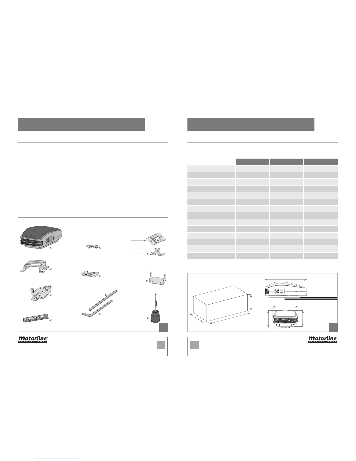
Inside the package you will find the following components:
TECHNICAL SPECIFICATIONS
02. PACKAGE 03. THE AUTOMATISM
INSIDE THE PACKAGE
The ROSSO EVO specifications are as follow:
The automatism ROSSO EVO dimensions are as follows:
ROSSO EVO 60 ROSSO EVO 100 ROSSO EVO 120
• Power Supply AC 230V 50/60Hz AC 230V 50/60Hz AC 230V 50/60Hz
• Motor's Power DC24V - 100W DC24V - 120W DC24V - 160W
• Velocity 140mm /sec 140mm /sec 140mm /sec
• Noise Level ≤56dB ≤56dB ≤56dB
• Force 600N 1000N 1200N
• Operating temperature -25°C a 70°C -25°C a 70°C -25°C a 70°C
• Thermal protection 120°C 120°C 120°C
• Protection grade IP20 IP20 IP20
• Working frequence 70% 70% 70%
• Courtesy Light 3 minutes 3 minutes 3 minutes
• Maximum door area 10m² 15m² 18m²
• Memory 30 transmitters 30 transmitters 30 transmitters
• Code Type Rolling Code Rolling Code Rolling Code
• Radio frequency 433,92Hz 433,92Hz 433,92Hz
01 • 01 motor
02 • 01 main rod
03 • 01 secondary rod
04 • 02 transmitters
05 • 01 mounting bracket
06 • 01 unlock string
07 • 03 motor’s fixing plate to the rail
08 • 01 rail’s fixing plate to the ceilling
09 • 01 rail’s fixing plate to the lintel
10 • 01 gate’s fixing plate
11 • 01 reinforcement plate to gate’s
fixing plate
12 • 01 stopper
• 01 set of fixing accessories
• 01 transmitter support
5A 5B
01
02
03
05
07 08
04
06
ENEN
03. THE AUTOMATISM 03. THE AUTOMATISM
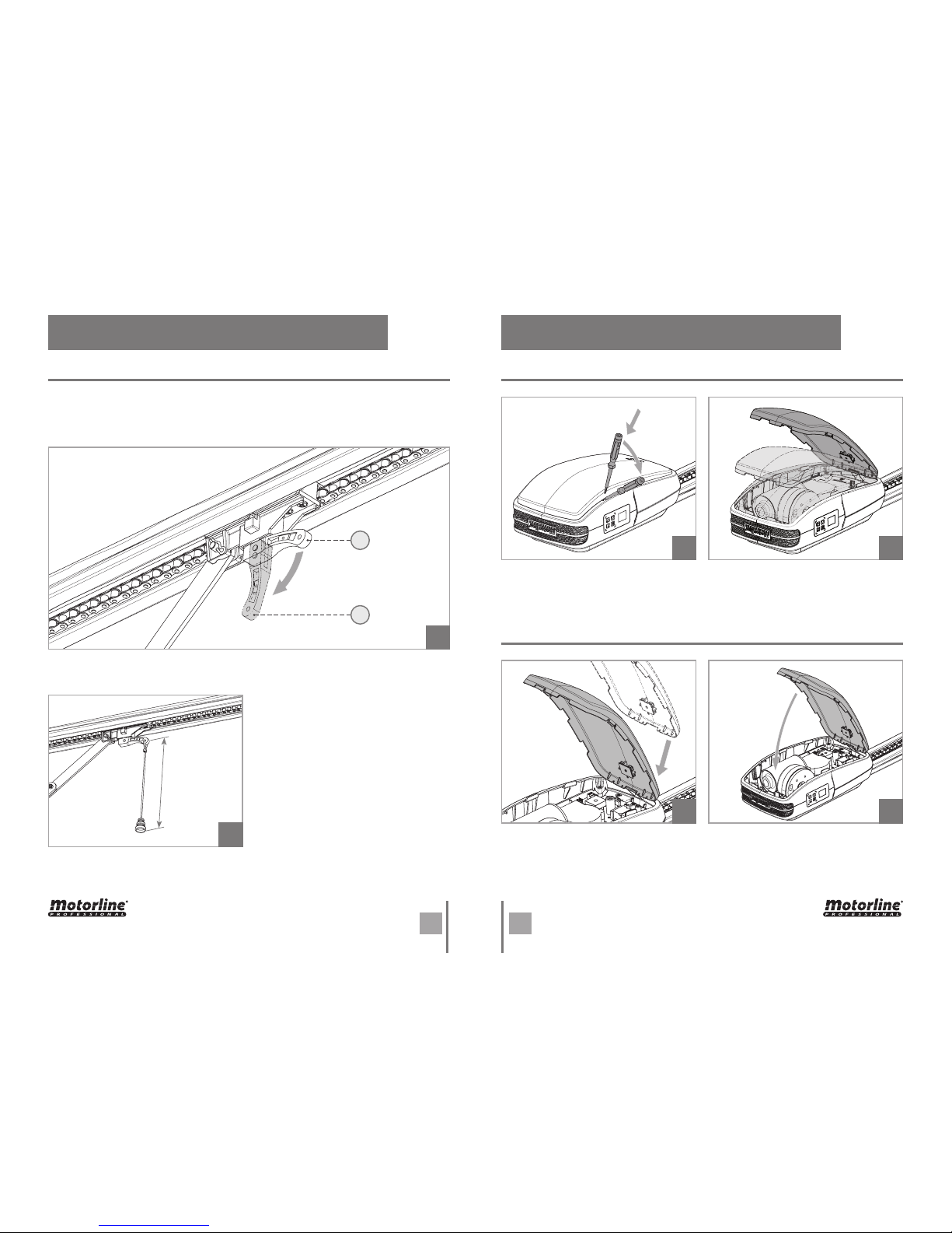
REMOVING TOP COVER
REPLACE TOP COVER
MANUAL BRAKE RELEASE
The ROSSO EVO unlocking system is very simple and practical to use. To do so just pull
the lever down (figure 03).
To block simply pull the lever to the original position.
To remove the cover simply insert a small screwdriver into the side holes, and create a
leverage effect to release the indents fittings between the top cover and the body. Then
just remove the cover by lifting it.
To replace the cover you must first fit the back as shown in the figure 07. Then simply
turn down the cover and fit the front pressing down. The fittings will automatically
secure the cover.
Position 01 • Motor locked
Position 02 • Motor unlocked
← Together with the automatism it is
also provided a string to apply on the
unlock lever, which makes it even a more
practical and comfortable process.
Maximum:
700mm
6A 6B
09
11
10
12
ENEN
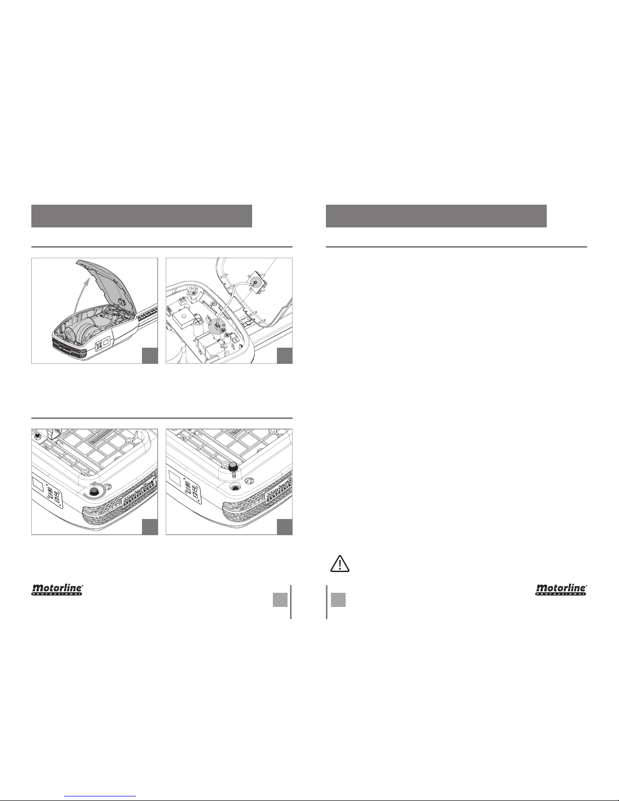
CHANGING COURTESY LEDS
03. THE AUTOMATISM 04. INSTALLATION
INFORMATION PRE-INSTALLATION
CHANGING FUSE
• To replace the LED board you must open the top cover and detach the wire of the LED
from the control board. Loosen the screw which secures the LED board to the top cover
and remove it. Now just put the new LED board, screw it, fit the wire in the control board
and close back the cover on the motor.
• To replace the fuse, first loosen it as visible in the image 11. Then just pull to remove it
(image 12). Repeat the same steps in reverse order to put a new fuse.
The operator uses a 250V 2,5A.
For a correct operation of ROSSO EVO, you must take into account the following
parameters before the installation:
• Read all steps on this manual at least once in order to get acquainted with the
installation and configuration process.
• Make sure the door’s structure is solid and appropriate to be automated.
• Verify that the sectional door has no technical defects, such as friction points/
prison, that may jeopardize the automatism durability.
• Make sure the door is in good condition to install the motor. To do so, raise it
manually to 800mm, 1600mm and 2000mm from the ground. Check if the door remains
suspended in these positions or descending. If the door starts to go up or down, it
means that the springs are not well calibrated.
• Check the surroundings. Carefully evaluate any hazards that may cause material
damage, possible insects contact, infiltration, among others.
• Make sure that the automatism will be connected to a 230V, properly protected with
Ground Wire.
• Make sure there is adequate protection against short-circuits / power surges and
earthed in the Electrical Box.
• Be careful when handling directly the control board. Improper handling can damage
some electrical components.
• Make sure you have all the necessary material prepared for installation.
• Evaluate the safety devices to be installed. This will ensure that unexpected
accidents do not happen.
It is very important that these precautions are respected!
Only in this way the correct functioning and automatism durability can be achieved!
 Loading...