

Motorline professional MC50SE Installation Manual
MC50SE
USER/INSTALLER MANUAL
EN
1 2
24V
v7.0
REV. 04/2019
. CONTENT
INDEX
. SAFETY INSTRUCTIONS
STANDARDS TO FOLLOW
. THE CONTROL BOARD
TECHNICAL SPECIFICATIONS
PROGRAMMING PRE-RECOMENDATIONS
. INSTALLATION
ESSENTIAL STEPS FOR INSTALLATION
TRANSMITTERS
"P" MENU FUNCTIONS
"E" MENU FUNCTIONS
. PROGRAMMING P
P0AUTOMATIC PROGRAMMING
P1SETTING THE DECELERATION TIME
P2SETTING STRENGTH AND SENSITIVITY
P4PAUSE TIME
P5PHOTOCELLS PROGRAMMING
P6STOP
P7OPERATING LOGIC
P8FLASHING LIGHT
P9DISTANCE PROGRAMMING
. PROGRAMMING E
E0PRESENT MAN
E1SOFT START
E2COURTESY LIGHT TIME
E3FOLLOW ME
E6DECELERATION SPEED
E7MANEUVERS COUNTER
E8RESET RESTORE FACTORY VALUES
E9RGB FLASHING LIGHT
. DISPLAY
DISPLAY INDICATIONS
2A
2B
3A
4A
4B
5A
5B
6A
6B
7A
7B
8A
8B
9A
9B
10A
10B
11A
11B
12A
12B
13A
13B
14A
14B
. COMPONENTS TEST
TEST SCHEME
INPUTS TEST
. TROUBLESHOOTING
INSTRUCTIONS FOR FINAL CONSUMERS/ TECHNICIANS
. CONNECTION SCHEME
CONTROL BOARD CONNECTIONS
15A
15B
16
17
PT
221
. SAFETY INSTRUCTIONS
STANDARDS TO FOLLOW
. THE CONTROL BOARD
TECHNICAL SPECIFICATIONS
ATTENTION:
This product is certified in accordance with European Community (EC) safety standards.
This product complies with Directive 2011/65/EU of the European Parliament and of the
Council, of 8 June 2011, on the restriction of the use of certain hazardous substances in
electrical and electronic equipment.
(Applicable in countries with recycling systems).
This marking on the product or literature indicates that the product and electronic
accessories (eg. Charger, USB cable, electronic material, controls, etc.) should not be
disposed of as other household waste at the end of its useful life. To avoid possible harm
to the environment or human health resulting from the uncontrolled disposal of waste,
separate these items from other types of waste and recycle them responsibly to promote the
sustainable reuse of material resources. Home users should contact the dealer where they
purchased this product or the National Environment Agency for details on where and how
they can take these items for environmentally safe recycling. Business users should contact
their vendor and check the terms and conditions of the purchase agreement. This product
and its electronic accessories should not be mixed with other commercial waste.
This marking indicates that the product and electronic accessories (eg. charger, USB cable,
electronic material, controls, etc.) are susceptible to electric shock by direct or indirect contact
with electricity. Be cautious when handling the product and observe all safety procedures in this
manual.
• It is important for your safety that these instructions are followed.
• Keep these instructions in a safe place for future reference.
• The ELECTROCELOS S.A. is not responsible for the improper use of the product, or other use than that for which
it was designed.
• The ELECTROCELOS S.A. is not responsible if safety standards were not taken into account when installing the
equipment, or for any deformation that may occur.
• The ELECTROCELOS S.A. is not responsible for insecurity and malfunction of the product when used with
components that were not sold by the them.
• This product was designed and manufactured strictly for the use indicated in this manual.
• This control board is not appropriate for inflammable or explosive environments.
• Any other use not expressly indicated may damage the product and/or can cause physical and property damages,
and will void the warranty.
• Do not make any changes to the automation components and/or their accessories.
• Control board for indoor use with 230V connection.
• Keep remote controls away from children, to prevent the automated system from being activated involuntarily.
• The customer shall not, under any circumstances, attempt to repair or tune the automatism. Must call qualified
technician only.
• The installer must have certified professional knowledge at the level of mechanical assemblies in doors and
gates and control board programmation. He should also be able to perform electrical connections in compliance
with all applicable regulations.
• The installer should inform the customer how to handle the product in an emergency and provide him the
manual.
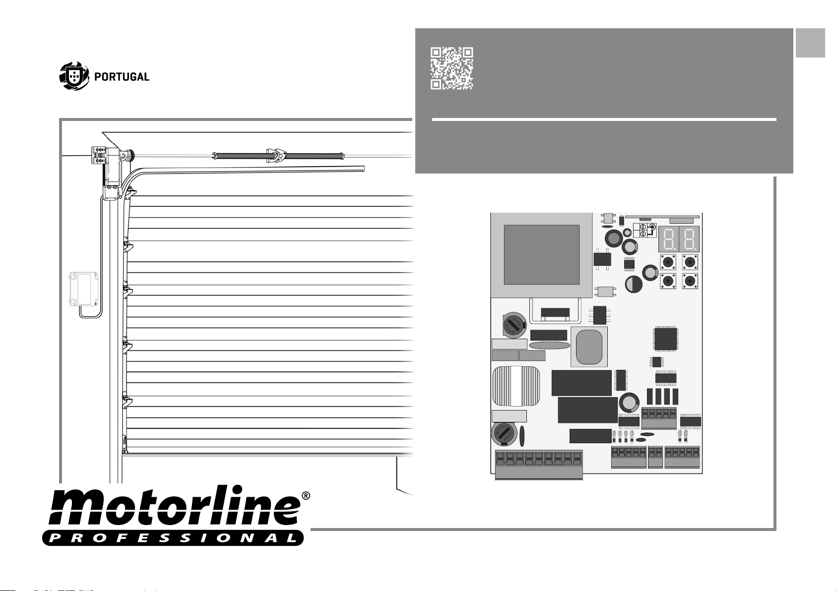
The MC50SE is a monophasic control board com a control system via incorporated rádio,
developed for the automation of sectional door.
• Power supply 230V AC 50-60Hz
• Lightbulb’s output 230V AC 50Hz 100W max.
• RGB Lightbulb’s output 24V DC 100mA max.
• Motor’s output 230V AC 50-60Hz 1000 W max.
• Auxiliary accessories output 24V DC 8 W max.
• Security and BT transmitters 24V DC
• Working temperature -10°C to + 55°C
• Incorporated Radio Receptor 433,92 Mhz
• OP Transmitters 12bits or Rolling Code
• Maximum Memory Capacity 100 (full opening)
• Control board Dimensions 105x130 mm.
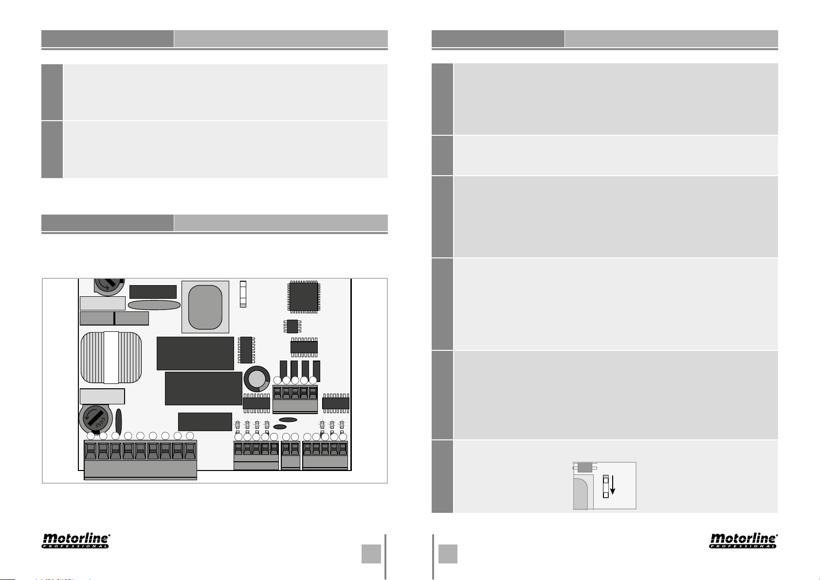
• CONNECTOR’S DESCRIPTION
01 • Grounding
02 • Grounding
03 • 230V Line Input (phase)
04 • 230V Line Input (neutral)
05 • 230V Motor’s Output – Opening
CN1
06 • 230V Motor’s Output – Common
07 • 230V Motor’s Output - Closing
08 • AC 230V Lightbulb Output
09 • AC 230V Lightbulb Output
01 • Close Push Button input
02 • Open Push Button input
03 • Motor’s opening limit-switch input (OPEN)
CN2
04 • Motor’s closing limit-switch input (CLOSE)
05 • Common
01 • 24V DC 200mA max power supply 24V
CN3
02 • 24V DC 200mA max power supply ( )
3A 3B2A 2B
ENEN
. THE CONTROL BOARD
TECHNICAL SPECIFICATIONS
. THE CONTROL BOARD
PROGRAMMING PRE-RECOMENDATIONS
01 • Safety Edge
02 • Photocells
03 • Encoder (not used)
CN4CN5
04 • Encoder (not used)
05 • Common
01 • +24V DC Auxiliary Power Supply for LED RGB flashing light
02 • Y output
03 • R output
04 • G output
05 • B output
. THE CONTROL BOARD
PROGRAMMING PRE-RECOMENDATIONS
To enhance knowledge about the control board operation, before proceeding to the
setup, give special attention to the instructions that follow.
Dipper
LS • LED lit when the close push button is active
LO • LED lit when the open push button is active
F0 • LED off when the opening limit switch is active
FC • LED off when the closing limit switch is active
LEDS
ST • LED off when STOP is active (when P6 is active)
LE • LED off when photocells are active (when P5 is active)
Courtesy light or flashing light:
08 and 09 • This output allows connection of a courtesy light or a flashing light
CN1
(see P8 in page 9B).
Limit switches:
03 and 04 • The control board needs a opening and closing limit-switches
connection (both in NC). Triggering any limit-switch will make the immediate
stoppage of the movement.
CN2
The limit-switch thriggering is visible on the display. OP (opening limit switch
activated) and CL (opening limit switch activated).
It is mandatory the use of limit switches.
Safety circuits:
01 • This input allows connection of STOP device. The device could be activeted
or desactiveted in the P6 menu (page 8B).
02 • This input allows connection of photocells. The device operates according
CN4
to programming set in the P5 menu (page 8A)
Shunt application is not necessary.
04 • It allows the connection of a pushbutton of singular botton for up and
down of the door.
01 • Auxiliary output for flashing light or 24V DC LED.
2
1
3
4
5
Open collector for the management of auxiliary functions:
02 • The y output is activated in the initial 2 seconds of the movement to control
the second capacitor.
CN5
LSLOFOLAFC
2
1
3
6
4
5
8
7
9
1
2
3
4
CN5
5
LE PU
11
22
3
4
5
03 • The R output is activated in intermittent mode, only in closing phase.
04 • The G output is activated in intermittent mode, only in opening phase.
05 • The B output is activated in intermittent mode, only in pause time
.
The dipper indicates the motor's power rating. Put the dipper in this position.
24V
CN1
CN2 CN3 CN4
Dipper
4A 4B
3A 3B
ENEN
. INSTALLATION
ESSENTIAL STEPS FOR INSTALLATION
. INSTALLATION
TRANSMITTERS
The installation process assumes that the gate has already limit switches
plates installed. For more information consult the motor's manual.
01 • Make the connections of all the accessories according to the connection scheme
(page 17).
02 • Connect the control board to a 230V power supply (3 and 4 - CN1 terminals).
03 • Make sure that the gate movement is the same as the one shown on the display:
If the display does not match the gate's
movement, turn off the control board from
the power supply e swap the 5 and 7 wires
CLOSING OPENING
from CN1 and check if it is correct with 3
and 4 from CN2.
04 • Check is the limit switches, so that the FC LED turns off during the closure and the
LED FO turns off during the opening.
05 • Make an automatic programming - P0 menu (page 6A).
06 • If necessary, adjust the gate of the deceleration time in opening and closing - P1
menu (page 6B).
07 • Adjust the strength and sensitivity of the motor - P2 menu (page 7A).
08 • Make an automatic programming of the course again - P0 menu (page 6A).
09 • Enable or disable the use of photocells in the P5 menu (page 8A).
10 • Enable or disable the use of safety band in the P6 menu (página 8B).
11 • Program a transmitter (page 4B).
The control board is now fully configured!
Check the menus from the programming pages in case you wish to configure other
features of the plant.
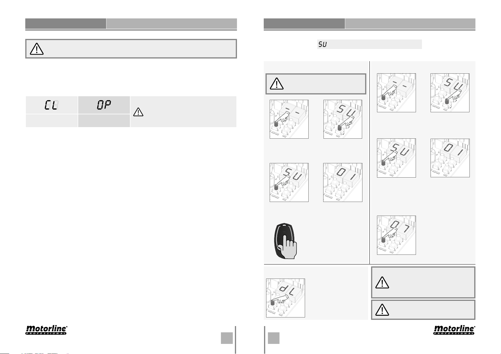
Transmitter programming for total opening.
• PROGRAMMING TRANSMITTERS
To program transmitters, you must
close the gate or turn the power
OFF and ON again.
01 • Press the
cmd button for
3sec.
03 • Press cmd
once to confirm.
05 • Press the command
button you want to program.
The display will blink and
move to the next free
location.
02 • SU appears.
04 • The first free
position appears.
• ERASE TRANSMITTERS
01 • Press the
cmd button for
3sec.
03 • Press cmd
once to confirm.
05 • Press cmd for 3sec
and the location will be
empty.
The display will show
the following location
with memorized
transmitter.
02 • SU appears.
04 • Use
to select the
transmitter
location you want
to delete.
↑↓
• ERASE ALL THE TRANSMITTERS
5A 5B4A 4B
• Whenever you save or delete a
01 • Press the
cmd button for 10sec.
02 • The display will show
dL, confirming that all
transmitters have been
erased.
transmitter, the display will show the
following location. You can add or
delete transmitters without having
to go back to point 01.
• If you do not press any key for 10
sec. the control board will return to
standby.
ENEN
. INSTALLATION
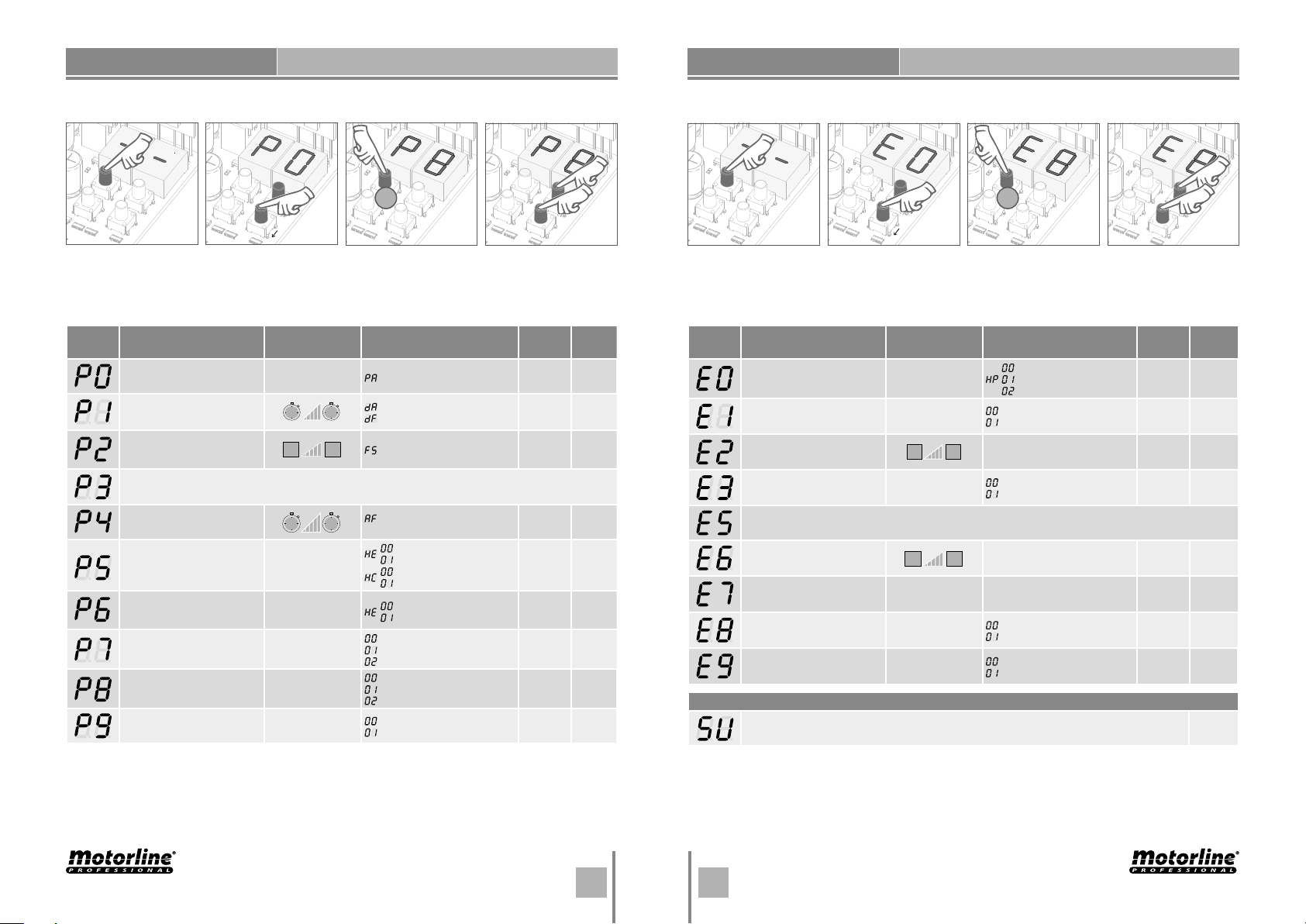
"P" MENU FUNCTIONS
. INSTALLATION
• We can only go into programming with a electrically closed gate. • We can only go into programming with a electrically closed gate.
"E" MENU FUNCTIONS
• To access the P menu
press the MENU key
for 3sec.
MENU FUNCTION
Course automatic
programming
Deceleration time
adjustment
Force and
sensibility adjustment
Pause time
Photocells programming
STOP
OperatiNG logic
Flashing light
Distance programming
• Use
↑↓
to navigate
through the menus.
MAX. MIN.
PROGRAMMABLE
0s
min. max.
1
min. max.
1s
min. max.
1x
• Press MENU when
you want to confirm
access to a menu.
-
Automatic Programming
Opening deceleration
15s
Closing deceleration
Sensibility adjustment
9
DISABLE MENU
Total closure pause time
99s
adjustment
photocells Disabled
-
-
-
-
-
photocells Activated
Photocells in closing
Photocells in opening
Security Band Disabled
Security Band Activated
Automatic mode function
Step by step mode function
Mode condominium function
Flashing (opening and closing)
Step by step mode function
Courtesy light
Distance PGM OFF
Distance PGM ON
STATE
• Press
↑↓
simultaneously to
exit programming.
FACTORY
VALUE
-
sec
PAGE
6A
6B
7A
7B
8A
8B
9A
9B
10A
• To access the E menu
press the MENU key
for 10sec.
MENU FUNCTION
Present Man
Soft start
Courtesy light time
Follow me
Deceleration speed
Operation counter
Reset - Restore factory settings
RGB Output
Transmitter programming for total opening.
• Use
↑↓
to navigate
through the menus.
MÁX. MIN.
PROGRAMABLE
0
min. max.
1
min. max.
1x
• Press MENU when
you want to confirm
access to a menu.
-
-
-
Deactivates present man
Activates present man
Activates present man - closing
Deactivates Soft start
Activates Soft start
Courtesy light time adjustment
99
Deactivates follow me
Activates follow me
DISABLE MENU
Deceleration speed adjustment
9
-
-
-
TRANSMITTER
Shows the number of maneuvers
Deactivated
Reset activated
Continued output
Intermittent output
STATE
• Press
↑↓
simultaneously to
exit programming.
FACTORY
VALUE
-
PAGE
10B
11A
11B
12A
12B
13A
13B
14A
B
6A 6B
5A 5B
ENEN
 Loading...