

Motorline professional mbm6 Installer And User Manual
MBM6 - Barrier
Installer and User’s manual
v2.0
REV. 11/2013
00. CONTENT
▷ INDEX STANDARDS TO FOLLOW ◁
01. SAFETY INSTRUCTIONS
00. CONTENT
▷ index | page 01.A
01. SAFETY INSTRUCTIONS
▷ standards to follow | page 01.B
02. PACKAGE
▷ inside package | page 02.A
03. OPERATOR
▷ technical specifications | page 02.B
▷ warning light | page 03.A
▷ locking / unlockin | page 03.B
04. INSTALATION
▷ installation site preparation | page 04.A
▷ barrier’s fixation | page 04.B
▷ boom assembly | page 05.A
▷ boom support installation | page 05.B
▷ top cover removal | page 06.A
▷ spring adjustment | page 06.B
▷ boom leveling | page 07.A
▷ limit-switch and stoppers adjustment | page 07.B
05. CONTROL BOARD MC15 CONFIGURATION
▷ checking limit-switches connections | page 08.A
▷ barrier’s course configuration | page 08.B
▷ transmitters configuration | page 09.A
▷ pause time configuration | page 09.A
▷ Condominum function and potenciometers | page 09.B
06. TROUBLESHOOTING
▷ final consumers instructions | page 10.A
▷ specialized technicians intructions | page 10.A
07. COMPONENTS TEST
▷ connections scheme | page 11.A
08. MAINTENANCE
▷ maintenance | page 11.B
09. CONTROL BOARD CONNECTIONS
▷ MOTORLINE MC15 control board | page 12.A
ATTENTION:
▷ To ensure the safety of people, it is important that you read all the following
instructions.Incorrect installation or incorrect use of the product can cause physical
injury and material damage.
▷ Keep these instructions in a safe place for future reference.
▷ This product was designed and produced strictly for the use indicated in this
manual. Any other use, not expressly indicated here, could compromise the good
condition/operation of the product and/or be a source of danger.
▷ ELECTROCELOS SA is not responsible for the improper use of the product,
or other use than that for which it was designed.
▷ ELECTROCELOS SA is not responsible if safety standards were not taken
into account when installing the equipment, or for any deformation that may occur to
it.
▷ ELECTROCELOS SA is not responsible for the safety and proper operation
when using components not sold by them.
▷ Do not make any modifications to the operator components and / or their
accessories.
▷ Beore installation unplug the automatism from the source of power.
▷ The installer must inform the client how to handle the product in case of
emergency and provide this manual to user.
▷ Keep remote controls away from children, to prevent the automated
system from being activated involuntarily.
▷ The customer shall not, under any circumstances, attempt to repair or tune
the operator .Must call qualified technician only.
▷ Connect the automatism to a 230V plug with ground wire.
▷ Operator for outdoor and indoor use.
01.A 01.B
02. PACKAGE
▷ INSIDE PACKAGE TECHNICAL SPECIFICATIONS ◁
03. OPERATOR
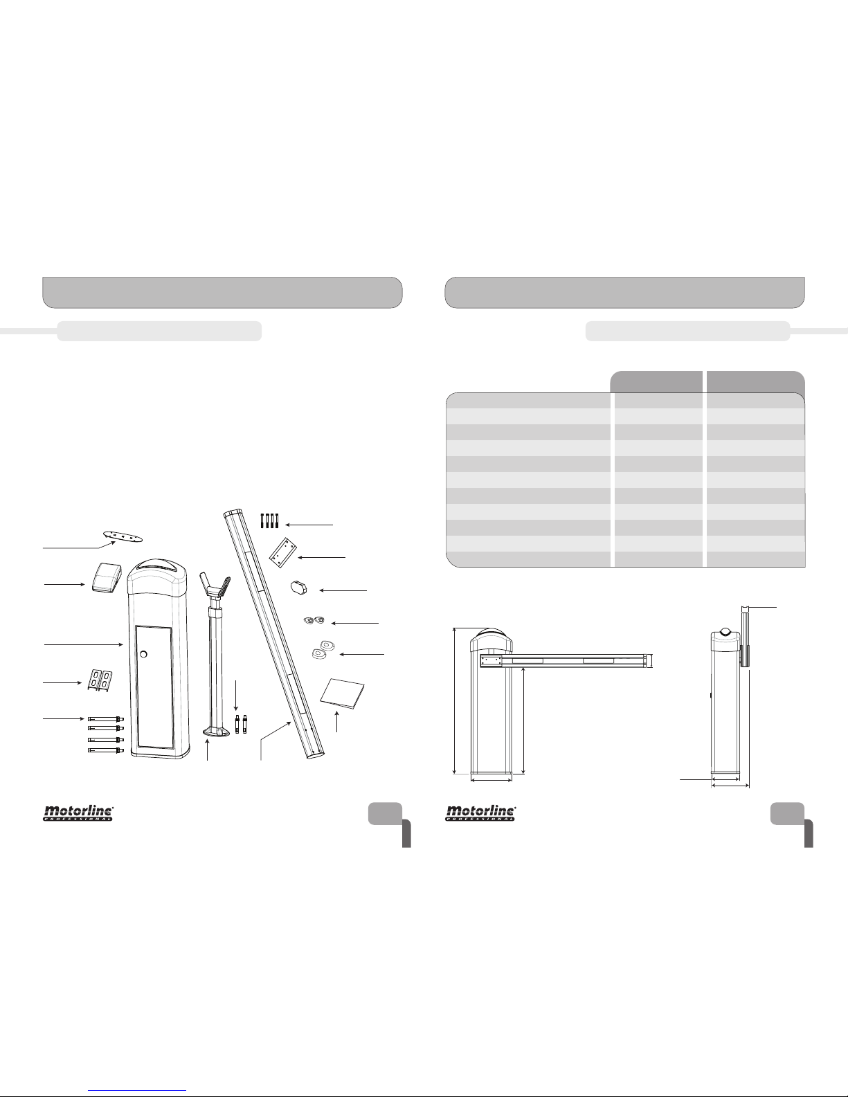
Inside the package you will find the following components:
▷ 01 electromechanical
▷ 01 MC15 control board
▷ 02 4channel MX4SP transmitter
▷ 01 aluminium boom
▷ 01 boom support
▷ 01 MF1 exterir photocells set
▷ 02 fastening metal plates
02.A 02.B
Electromechanical
barrier
Aluminum
boom
Boom
support
Boom
support
fastening
screws
Boom
fastening screws
RGB LED board
Boom
cover
MC15
control board
M16 screws
with bushings
Fastening
metal plates
Boom
metal plate
Installer and
user’s manual
MX4SP
transmitter
MF1
photocells
▷ 01 boom fastening metal plate
▷ 04 M16 bolts with bushings
▷ 04 boom fastening screws
▷ 02 boom support fastening screws
▷ 01 RGB LED board
▷ 01 cover for boom
▷ 01 installer and user’s manual
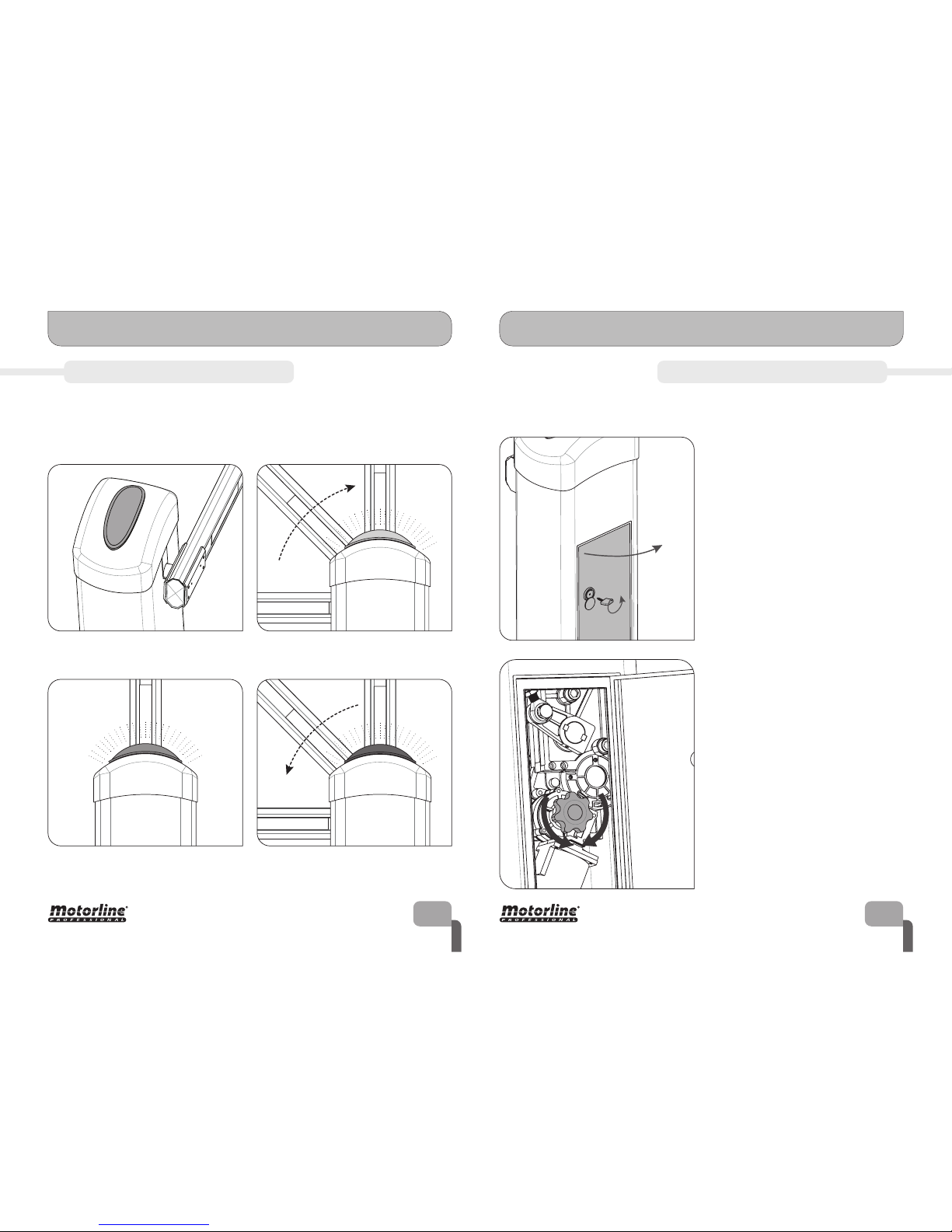
The specifications of the MBM6 barrier are:
The main dimensions of the MBM6 barrier are:
▷ Barrier’s Power Supply
▷ Power
▷ Current
▷ Working temperature
▷ Thermal protection
▷ Working frequency
▷ Noise level
▷ Opening / Closing time
▷ RPM
AC 230V 50/60Hz
90W
0,75 A
-45°C a 65°C
120°C
80%
<65dB
3 - 6 s
2800RPM
AC 230V 50/60Hz
▷ Motor’s Voltage AC 230V 24v DC
80W
0,75 A
-45°C a 65°C
-
Intense
▷ Protection level
IP55
IP55
<65dB
3 - 6 s
1400 RPM
MBM6 230 v MBM6 24 v
840 mm
1170 mm
100 mm
321 mm
214 mm
296 mm
53 mm
03. OPERATOR
▷ WARNING LIGHT LOCKING / UNLOCKING ◁
03. OPERATOR
03.A 03.B
The MBM6 barrier is a product developed with the purpose of controlling the access of
vehicles to private, industrial and commercial areas.
One of the main functionalities is the warning light capable of emitting dierent colors.
This was developed to identify the dierent stages of the boom (opening, openned and
closing) in a more clear and visible way.
DETAIL: Barrier’s warning light During opening course - warning light
emits GREEN light
During pausing time while openned warning light emits BLUE light
During closing course - warning light
emits RED light
In case of power failure, the barrier is equipped with a manual unlocking and locking
system. Follow the bellow instructions to unlock or lock the barrier.
1▷ Open the door using the key supplied
with the barrier. Rotate the key to unlock
the door and pull it towards outside.
On the interior, you will have access to the
unlocking system.
2▷ The unlocking is made by pressing and
rotating the motor wheel shaded on the
image on the side. The rotation direction to
unlock will depend on the current stage of
the boom (opened or closed) which will make
the rotation possible to only one side.
You must rotate the red wheel to the
easiest side.
To lock the barrier, you must do the same
steps because once it is unlocked, the red
wheel will only be able to rotate to one of the
sides.
 Loading...