

Motorline professional LINCE400, LINCE300, LINCE600 User Manual
v8.0
REV. 03/2018
EN
USER’S AND INSTALLER’S MANUAL
LINCE 230V/110V/24V
2A 2B
01B
10A
10B
11A
12
13
03A
03B
05B
09
04B
07A
09
05A
08
ENEN
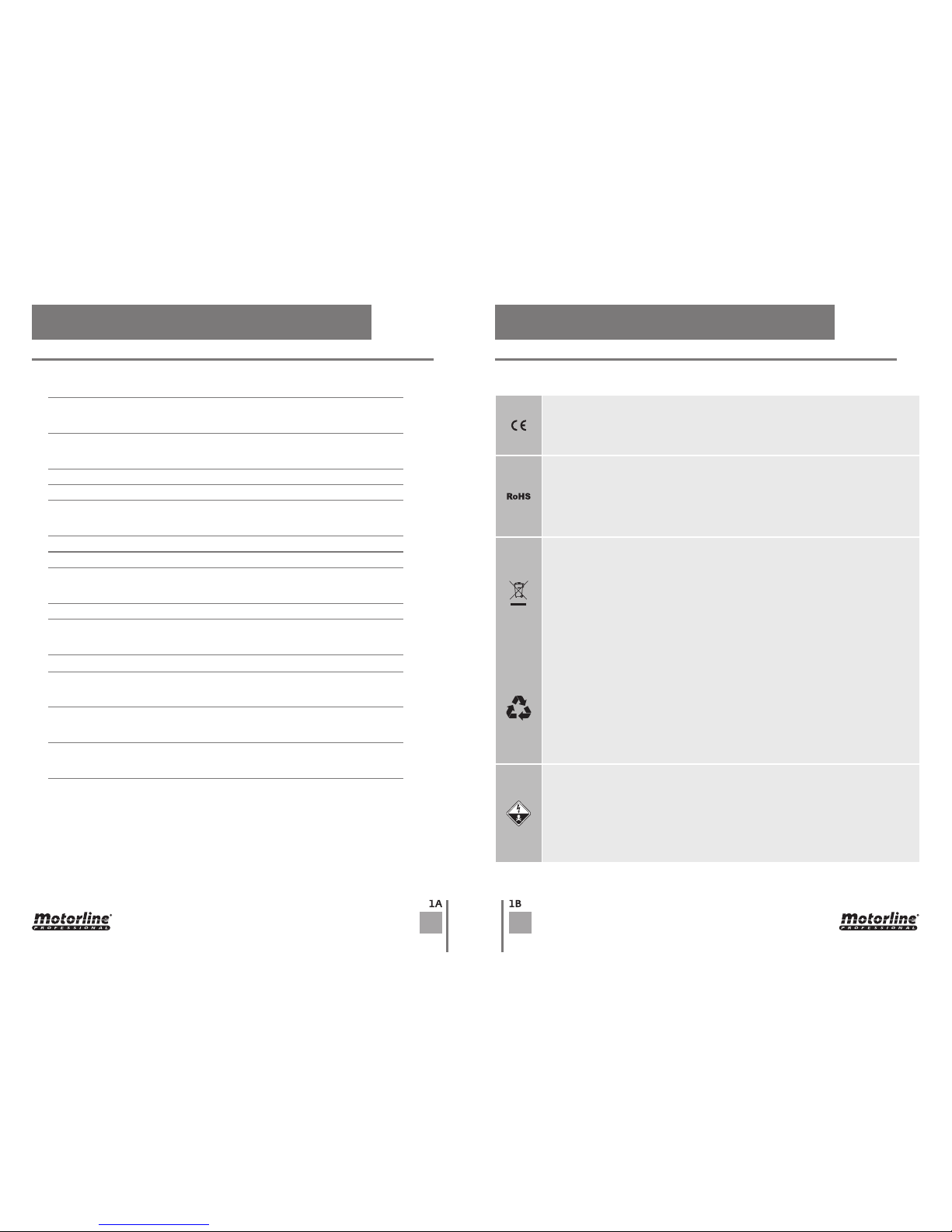
ATTENTION:
This product is certified in accordance with European Community
(EC) safety standards.
This product complies with Directive 2011/65/EU of the European
Parliament and of the Council, of 8 June 2011, on the restriction of
the use of certain hazardous substances in electrical and electronic
equipment.
(Applicable in countries with recycling systems).
This marking on the product or literature indicates that the product
and electronic accessories (eg. Charger, USB cable, electronic material,
controls, etc.) should not be disposed of as other household waste at
the end of its useful life. To avoid possible harm to the environment
or human health resulting from the uncontrolled disposal of waste,
separate these items from other types of waste and recycle them
responsibly to promote the sustainable reuse of material resources.
Home users should contact the dealer where they purchased this
product or the National Environment Agency for details on where and
how they can take these items for environmentally safe recycling.
Business users should contact their vendor and check the terms and
conditions of the purchase agreement. This product and its electronic
accessories should not be mixed with other commercial waste.
This marking indicates that the product and electronic accessories
(eg. charger, USB cable, electronic material, controls, etc.) are
susceptible to electric shock by direct or indirect contact with
electricity. Be cautious when handling the product and observe all
safety procedures in this manual.
STANDARDS TO FOLLOW
230V/110V MOTOR
24V MOTOR
MAINTENANCE
CONNECTIONS SCHEME 230V/110V
CONNECTIONS SCHEME 24V
INSIDE PACKAGE
CHANGE MOTOR DIRECTION
INSTALLATION DIMENSIONS
FINAL CONSUMERS INSTRUCTIONS
MANUAL RELEASE
INSTALLATION STEPS
INSTRUCTIONS FOR SPECIALIZED INSTALLERS
TECHNICAL SPECIFICATIONS
INSTALLATION MAP
01. SAFETY INSTRUCTIONS
06. COMPONENTS TEST
07. MAINTENANCE
08. CONTROL BOARD MC2
09. CONTROL BOARD MC11
02.PACKAGE
03. OPERATOR
04. INSTALLATION
05. TROUBLESHOOTING
00. CONTENT 01. SAFETY INSTRUCTIONS
INDEX STANDARDS TO FOLLOW
3A 3B
ENEN
01. SAFETY INSTRUCTIONS 01. SAFETY INSTRUCTIONS
STANDARDS TO FOLLOW STANDARDS TO FOLLOW
• It is important for your safety that these instructions are followed.
• Keep these instructions in a safe place for future reference.
• The ELECTROCELOS S.A. is not responsible for the improper use of the product,
or other use than that for which it was designed.
• The ELECTROCELOS S.A. is not responsible if safety standards were not taken
into account when installing the equipment, or for any deformation that may
occur.
• The ELECTROCELOS S.A. is not responsible for insecurity and malfunction of the
product when used with components that were not sold by the them.
• This product was designed and manufactured strictly for the use indicated in
this manual.
• This control board is not appropriate for inflammable or explosive environments.
• Any other use not expressly indicated may damage the product and/or can
cause physical and property damages, and will void the warranty.
• Do not make any changes to the automation components and/or their accessories.
• Control board for indoor use with
24Vdc/110Vac/230Vac
connection.
• Keep remote controls away from children, to prevent the automated system
from being activated involuntarily.
• The customer shall not, under any circumstances, attempt to repair or tune the
automatism. Must call qualified technician only.
• The installer must have certified professional knowledge at the level of
mechanical assemblies in doors and gates and control board programmation.
He should also be able to perform electrical connections in compliance with all
applicable regulations.
• The installer should inform the customer how to handle the product in an
emergency and provide him the manual.
• This device can be used by children 8 year old or older and persons whose
physical, sensory or mental capacities are reduced, or by persons without
experience or knowledge if they have received supervision or instructions on
the use of the device in a safe manner and understood the hazards involved.
Children should not play with the device. Cleaning and maintenance by the user
must not be carried out by unsupervised children.
• Automatism powered by very low safety voltage, with electronic board/control
board/control unit (only applicable to 24V motors).
• Before installing, the installer must verify that the temperature range indicated
on the automatism is appropriate to the location of the installation.
• Before installing, the installer must verify that the equipment to be automated is
in good mechanical condition, correctly balanced and opens and closes properly.
• If the automation is to be installed at a level higher than 2,5 m above ground
level or other level of access, , should be followed the minimum safety and
health requirements for the use of work equipment workers at work in Directive
2009/104/EC of the European Parliament and of the Council of 16th September
of 2009.
• In the case of the equipment where the automation will be installed, have
a pedestrian door, be aware that it must be closed when the automation is
activated.
• After installation, make sure that the mechanism is properly adjusted and that
the protection system and any manual unlocker works correctly.
• In order to protect the electrical cables against mechanical stress, you should
use conduit for the electrical wires, essentially on the power cable.
• When programming the control unit, pay particular attention to touching only
the location intended for that purpose. Failure to do so may result in electric
shock.
• Replacement of the power cable in the automation can only be carried out by
specialized technicians or by the manufacturer.
4A 4B
01
04
05 06
03
810mm
280mm
210mm
07•
03•
09•
04•
06•
01•
02•
08•
05•
02
ENEN
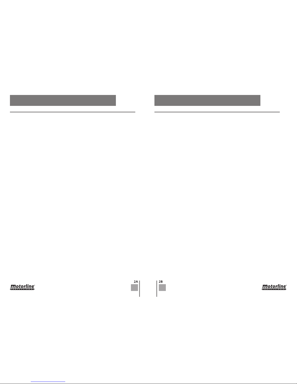
In the package you will find the following components:
01• 02 Swing operators LINCE
02• 01 Control Board
03• 02 transmitters
04• 02 Front supports
05• 02 Rear supports
06• 02 Capacitors [only available with the 230V (8µF) and 110V(20µF) models]
07• 01 Photocells
08• 01 User’s manual
09• 02 Release keys
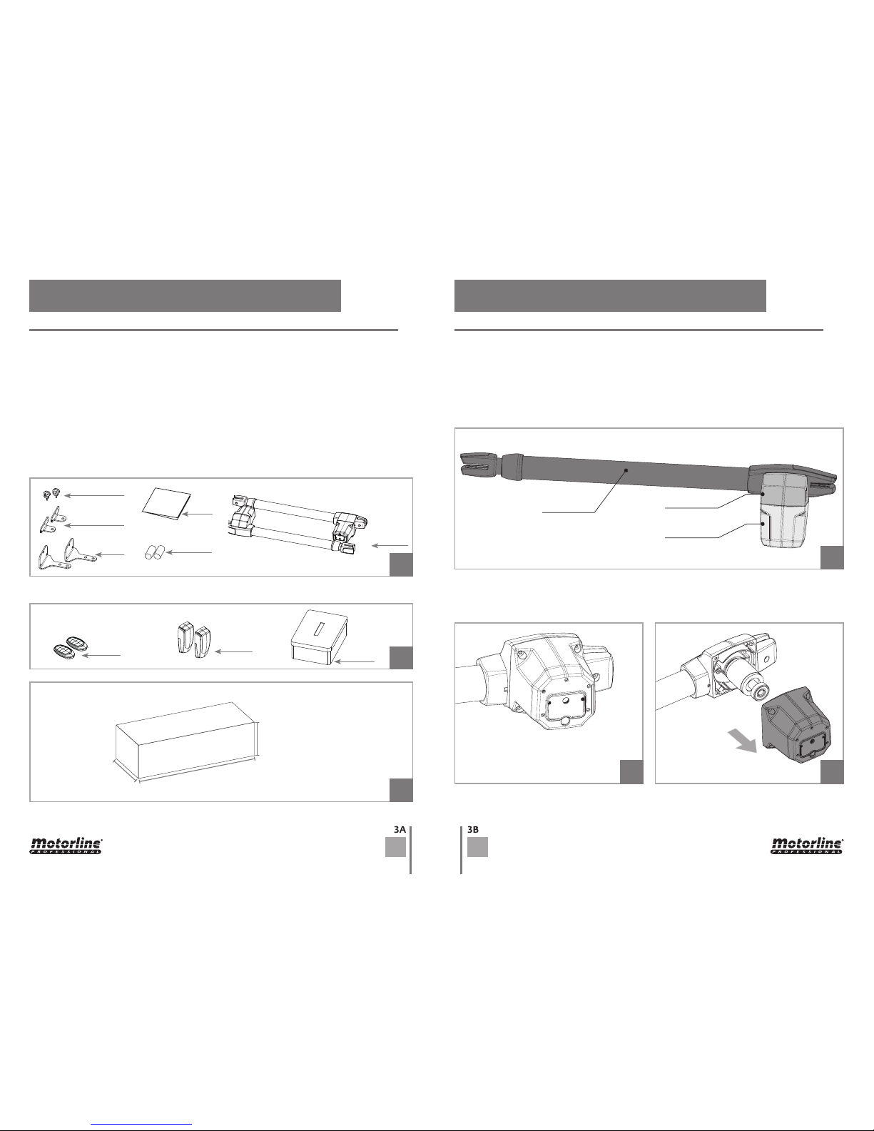
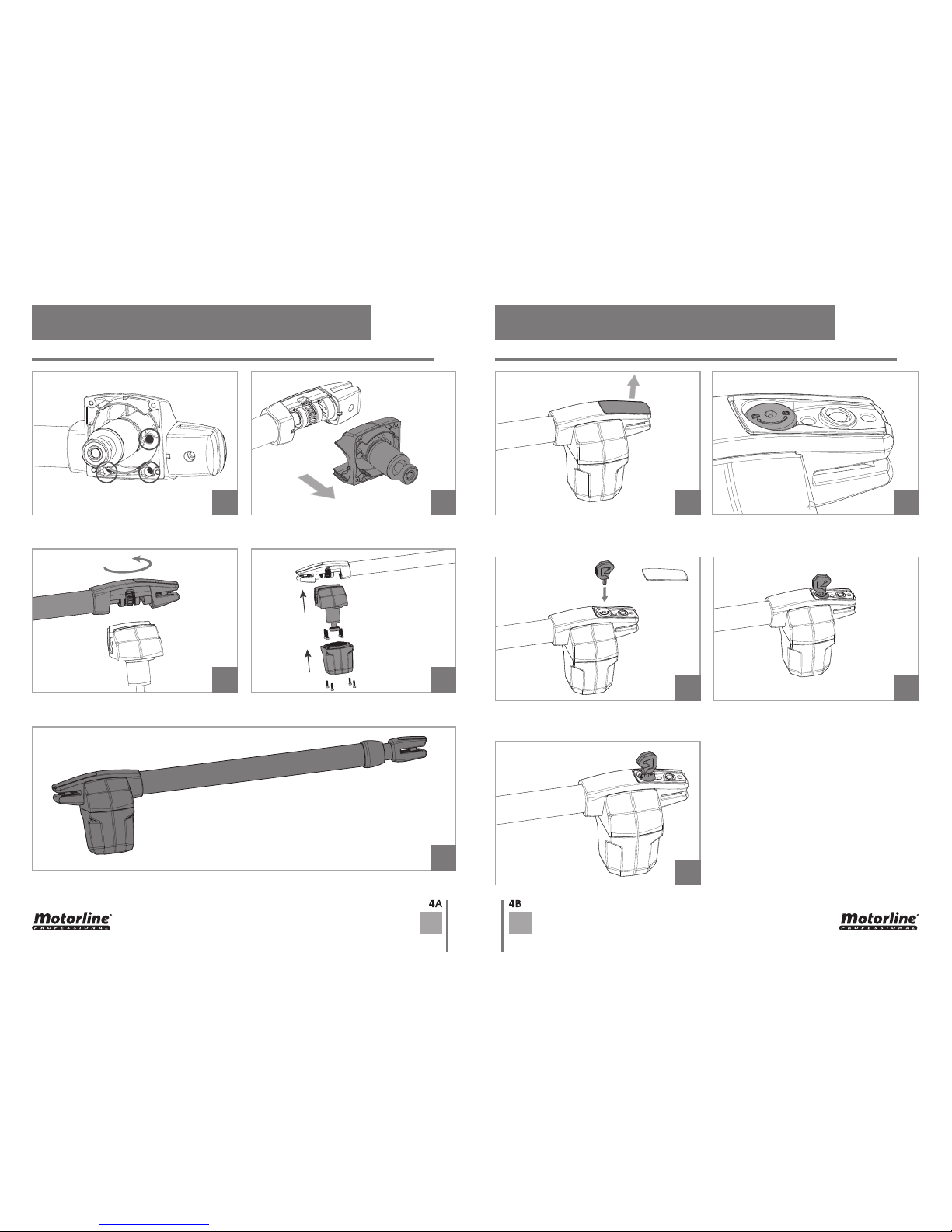
01 • Loosen the screws that secure the
Lower Part to Middle Part.
02 • Remove Lower Part.
The operator LINCE, is a product developed exclusively for the automatic opening of swing
gates.
Besides being pratical, safe and powerful, this product has a new function incorporated so
that you can transform a motor to apply on right leaves to left leaves.
This allows greater flexibility in the use of each operator.
Motor disassembly and assembly process, in order to transform motor, must be done as
follows:
Upper part
Middle part
Lower part
Electronic components the kit:
02. PACKAGE 03. OPERATOR
INSIDE PACKAGE CHANGE MOTOR DIRECTION
5A 5B
07
09
08
12
14
16
13
15
10
11
ENEN
03 • Loosen the screws of the Middle Part. 01 • Remove the plastic cap from the rear
end.
02 • Insert Release key on the unlock shaft.
03 • Rotate key 180 ° in the direction indicated
in the figure to unlock.
04 • Operator unlocked.
Note • To lock operator so it can work
automatically, must do it by turning the key
anticlockwise.
Information engraved on the unlock shaft.
D=Unlock || B=Lock
05 • Rotate Upper Part 180°. 06 • Assemble operator by tightening all
components with the screws.
07 • Full transformed operator.
04 • Remove Middle Part.
03. OPERATOR 03. OPERATOR
CHANGE MOTOR DIRECTION UNLOCK OPERATOR
 Loading...