

Motorline professional CSV100, CSV200 Installer And User Manual
v1.0
REV.10/2017
CSV100|200
INSTALLER AND USER’S MANUAL
EN
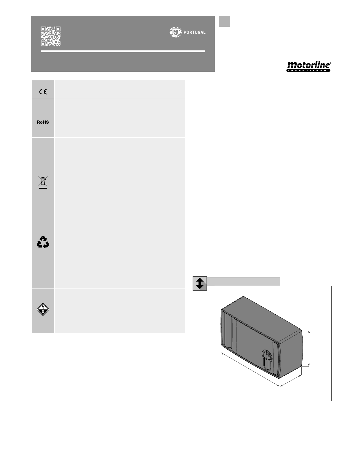
70,5mm
48mm
130mm
• It is important for your safety that these instructions are
followed.
• Keep these instructions in a safe place for future reference.
• The ELECTROCELOS S.A. is not responsible for the improper
use of the product, or other use than that for which it was
designed.
• The ELECTROCELOS S.A. is not responsible if safety
standards were not taken into account when installing the
equipment, or for any deformation that may occur.
• The ELECTROCELOS S.A. is not responsible for insecurity
and malfunction of the product when used with components
that were not sold by the them.
• This product was designed and manufactured strictly for
the use indicated in this manual.
• Any other use not expressly indicated may damage the
product and/or can cause physical and property damages,
This product is certified in accordance with
European Community (EC) safety standards.
This product complies with Directive 2011/65/
EU of the European Parliament and of the
Council, of 8 June 2011, on the restriction of
the use of certain hazardous substances in
electrical and electronic equipment.
(Applicable in countries with recycling systems).
This marking on the product or literature
indicates that the product and electronic
accessories (eg. Charger, USB cable, electronic
material, controls, etc.) should not be disposed
of as other household waste at the end of
its useful life. To avoid possible harm to the
environment or human health resulting from the
uncontrolled disposal of waste, separate these
items from other types of waste and recycle
them responsibly to promote the sustainable
reuse of material resources. Home users should
contact the dealer where they purchased this
product or the National Environment Agency
for details on where and how they can take
these items for environmentally safe recycling.
Business users should contact their vendor
and check the terms and conditions of the
purchase agreement. This product and its
electronic accessories should not be mixed
with other commercial waste.
This marking indicates that the product and
electronic accessories (eg. charger, USB cable,
electronic material, controls, etc.) are susceptible
to electric shock by direct or indirect contact with
electricity. Be cautious when handling the product
and observe all safety procedures in this manual.
Fig. 01
and will void the warranty.
• Do not make any changes to the automation
components and/or their accessories.
• The customer shall not, under any circumstances,
attempt to repair or tune the automatism. Must call
qualified technician only.
• The installer must have certified professional
knowledge at the level of mechanical assemblies in
doors and gates and control board programmation.
He should also be able to perform electrical
connections in compliance with all applicable
regulations.
• The installer should inform the customer how to
handle the product in an emergency and provide
him the manual.
• This device can be used by children 8 year old
or older and persons whose physical, sensory or
mental capacities are reduced, or by persons without
experience or knowledge if they have received
supervision or instructions on the use of the device
in a safe manner and understood the hazards
involved. Children should not play with the device.
Cleaning and maintenance by the user must not be
carried out by unsupervised children.
• Before installing, the installer must verify that the
temperature range indicated on the automatism is
appropriate to the location of the installation.
DIMENSIONS
70,5mm
48mm
130mm
Fig. 01
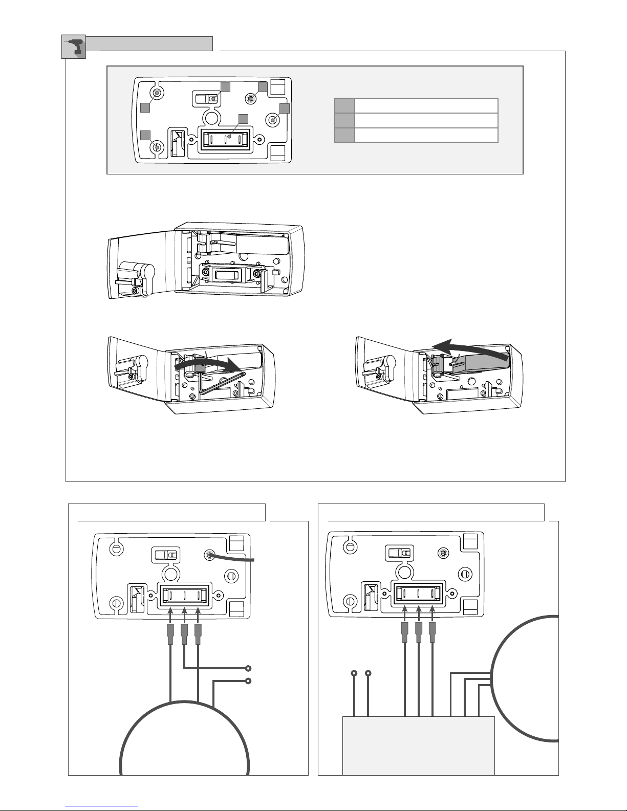
A
A
A
C
BB
MOTOR
MOTOR
CONTROL BOARD
• SWITCH CONNECTION TO THE MOTOR (CSV)
Brake wire
OPEN
OPEN
CLOSE
COMMON
CLOSE
PHASE
NEUTRAL
2 • Loosen the fixing screws of the push button.
Make the electric connection in the corresponding places.
NOTE • The electric cables should have isolated terminal
according to all electric safety standards.
3 • Remove the screw present in the cable clamp using a mm hex wrench and insert the unlock cable on the hole. When
the unlock cable is correctly stretched, tighten up the screw (fig.). Make sure that the motorreducer unlocks when you
push the handle (fig.). If the motorreducer is not completely unlocked, adjust the tightener. Finally cut any excess cable.
• SWITCH CONNECTION TO THE CONTROL BOARD (CSV)
INSTALLATION
• Prepare the output for the electric and unlock cables, respecting the preset sapaces on the switch box. Use the 3
fixation holes to fix the switch box to the wall.
A Fixation holes
B Entry for the unlock cable
C Button connection (CSV)
Fig. 02
Fig. 03
Fig. 04 Fig. 05
POWER
SUPPLY
POWER SUPPLY
 Loading...