

Motorline MC2 User's And Installer's Manual
v1.0
REV. 04/2015
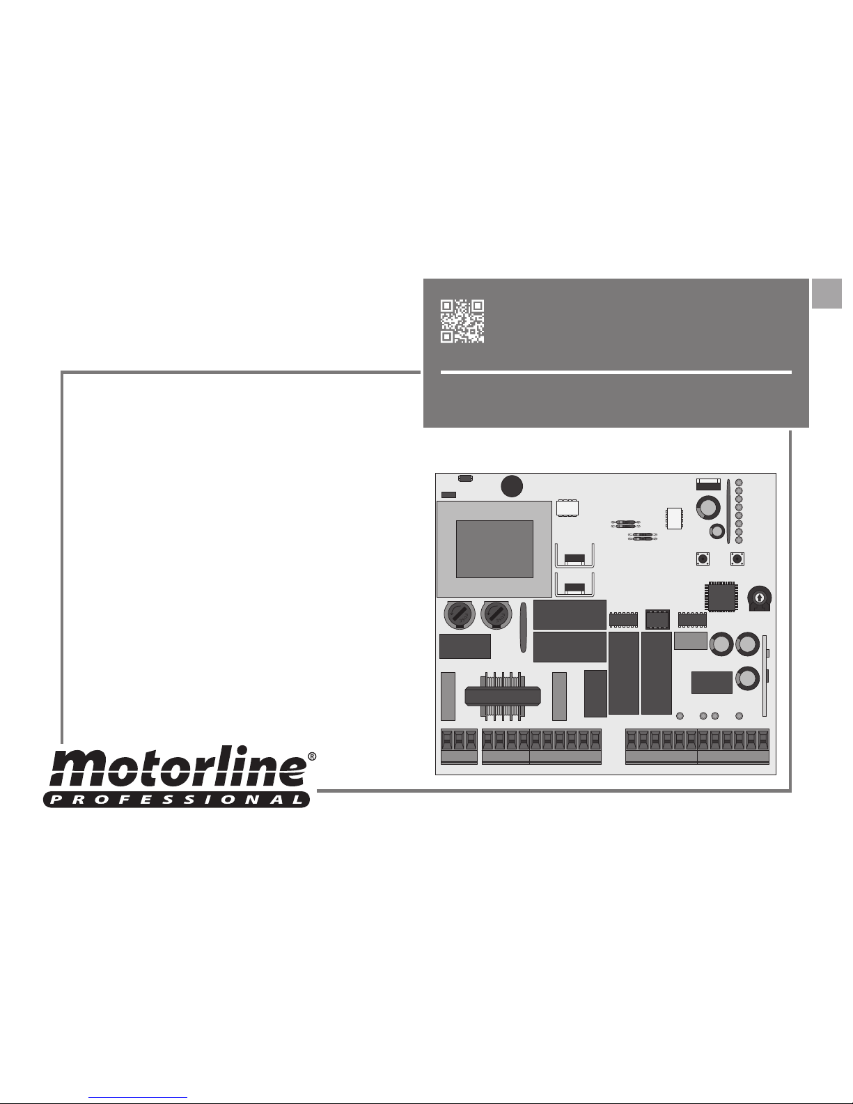
MC2
EN
USER / INSTALLER MANUAL
MC2
1A 1B
PTPT
INDEX
STANDARDS TO FOLLOW
00. CONTENT 01. SAFETY INSTRUCTIONS
1B
11
11
12
2A
3A
9B
10A
4A
10A
10B
6B
8A
ATTENTION:
• To ensure the safety of people, it is important that you read all the following instructions.
• Incorrect installation or incorrect use of the product can cause physical injury and
material damage.
• This product was designed and produced strictly for the use indicated in this manual.
Any other use, not expressly indicated here, could compromise the good condition/operation of the product and/or be a source of danger, and will void the warranty.
• ELECTROCELOS S.A. is not responsible for the improper use of the product, or other
use than that for which it was designed.
• ELECTROCELOS S.A. is not responsible if safety standards were not taken into account when installing the equipment, or for any deformation that may occur to it.
• ELECTROCELOS S.A. is not responsible for the safety and proper operation when
using components not sold by them.
• Do not make any modifications to the operator components and / or their accessories.
• Before installation unplug the automatism from the source of power.
• The installer must inform the client how to handle the product in case of emergency
and provide this manual to user.
• Keep remote controls away from children, to prevent the automated
system from being activated involuntarily.
• The customer shall not, under any circumstances, attempt to repair or tune the automatism. Must call qualifid technician only.
• Connect the automatism to a 230V plug with ground wire.
• Control board for indoor use.
STANDARDS TO FOLLOW
TECHNICAL SPECIFICATIONS
PROGRAMMING PRE-RECOMENDATIONS
MAIN MENU
EXTENDED MENU 3
PHOTOCELLS TESTING AND REMOTE CONTROLS
INSTRUCTIONS FOR FINAL CONSUMERS
EXTENDED MENU 1
RESET OF CONTROL BOARD
CAPACITATOR SCHEME
INSTRUCTIONS FOR SPECIALIZED INSTALLERS
EXTENDED MENU 2
01. SAFETY INSTRUCTIONS
02. THE CONTROL BOARD
03. CONFIGURATION
04. COMPONENT TEST
05. TROUBLESHOOTING
CONTROL BOARD CONNECTION COMPONENT
06. CONNECTION SCHEME
2A 2B
PTPT
02. THE CONTROL BOARD 02. THE CONTROL BOARD
TECHNICAL SPECIFICATIONS TECHNICAL SPECIFICATIONS
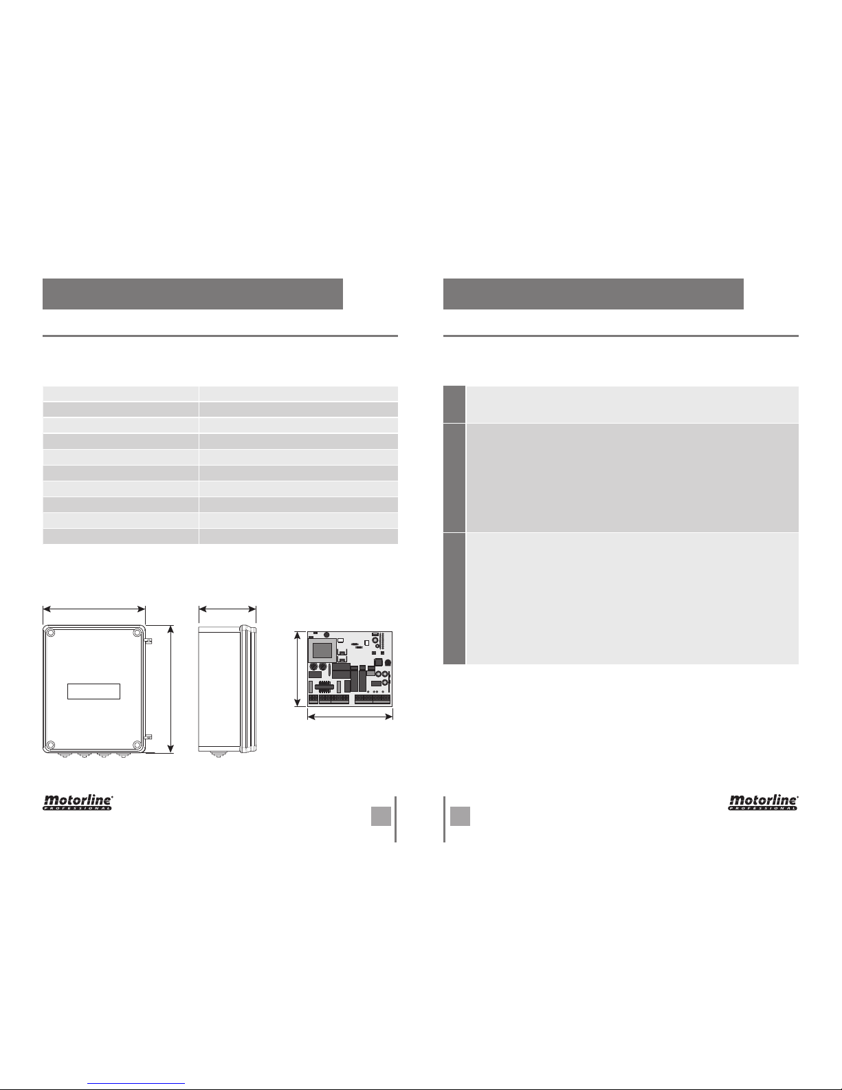
The MC2 is a central electronic single phase with incorporated radio, for automation of
swing gates.
• Power supply 230V AC 50-60Hz
• Lightbulb’s output 230V AC 500W máx.
• Motor’s output 230V AC 50/60 Hz 500W máx.
• Auxiliary accessories output
24V AC 15W máx.
• Safety and remote controls in BT 24V CC
• Working temperature -10˚C to +55˚C
• Protection IP56
• Incorporated Radio Receiver 433,92 Mhz
• OP Transmitters 12-18 bits or Rolling Code
• Maximum memory capacity 150 (CODE or CODE PED)
• CONNECTOR’S DESCRIPTION
• DIMENSIONS THE BOX AND CONTROL BOARD
01 • Earth connection
02 • Earth connection
03 • Earth connection
01 • AC 230V Line Input (PHASE)
02 • AC 230V Line Input (NEUTRAL)
03 • Lightbulb / Courtesy light’s output (not blink) AC230V (NEUTRAL)
04 • Lightbulb / Courtesy light’s output (not blink) AC230V (PHASE)
05 • Motor’s Output 1 opening
06 • Motor’s Output 1 common
07 • Motor’s Output 1 closing
08 • Motor’s Output 2 opening
09 • Motor’s Output 2 common
10 • Motor’s Output 2 closing
01 • Output for power photocells 24V AC
02 • Output for power photocells (earth)
03 • Output for electric lock 12V DC 15W (+12V)
04 • Output for electric lock 12V DC 15W (earth)
05 • Input PUL button the order opening / closing (NA)
06 • Input earth common
07 • Input PUL PED button the order pedestrian (NA)
08 • Input DS1 safety device 1 (NC)
09 • Input common GND
10 • Input DS2 safety device 2 (NC)
11 • Antenna mass input
12 • Antena hot pole input
CN2CN3 CN1
205mm 115mm
140mm
252mm
125mm
3A 3B
PTPT
02. THE CONTROL BOARD 02. THE CONTROL BOARD
PROGRAMMING PRE-RECOMENDATIONS PROGRAMMING PRE-RECOMENDATIONS
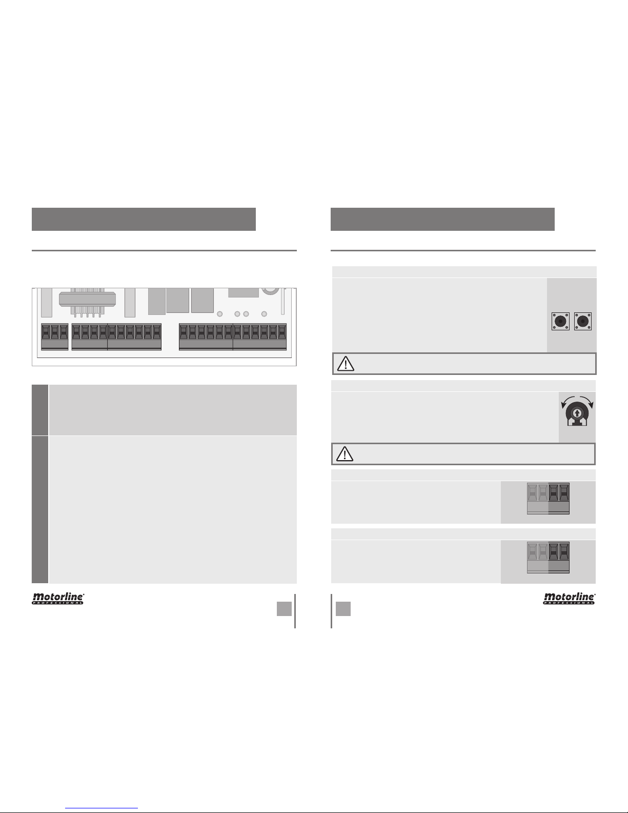
• POWER AND SPEED OF MOTORS
The control board has a trimmer VR1 for adjusting the force and speed
of the motors controlled by the microprocessor. The adjustment can be
effected between 50% and 100% the power.
At each start-up movement, the control board applies the maximum
power during 2 seconds, even when it is made regulating force to a value
than not the maximum.
FORZA
When you adjust the trimmer VR1 has to remake course programming, as they
could varied the times of maneuvering and deceleration.
+
-
• PROGRAMMING THE CONTROL BOARD - BUTTONS SEL/SET
SEL button: It makes the selection of the function to change. The selection is identified by the flashing of the LED corresponding to the
selected function at that time.
Pressing the SEL button repeatedly will cycle through the various
functions to be programmed. The selection remains active for 10 seconds, after these time the control board returns to original status
(no active selection).
SET button: Makes programming the selected function through the
SEL button.
The SET button may be substituted by a remote control from the latter is pro-
grammed.
SETSEL
• OPERATION OF FLASH LAMP
The operation of the output is conditioned by the movement of the motor and automatic closing. When the
automatic closing is activated, the 230V output is activated even during pause time.
3 4
• OPERATION WITH TIMER
Instead of a push button opening / closing (PUL), the
control board can be operated with a TIMER. With a
TIMER connected to the control board it is possible
to program an exact time for that the motor perform
both the opening and closing, in the automatic mode.
5 6
CN3
CN2
Flash lamp:
03 and 04 • This output allows connection of a flash lamp (see page 4B).
Capacitor:
05 and 07 • You must connect the capacitor between the outputs 05 and 07.
08 and 10 • You must connect the capacitor between the outputs 08 and 10.
Electric lock:
03 and 04 • This output allows connection of an electric lock (see pág.9A)
Push button / selector:
05 • Allows connection the push-button / selector to full opening (NA).
06 • Allows connection the push-button / selector to full opening (NA).
Safety circuits:
08 • This circuit allows the connection of all types of safety devices such as
photocells, safety edge, etc.
This device operates only in the gate closing and, when activated change the
direction of the automation.
10 • This circuit allows the connection of all types of safety devices such as
photocells, safety edge, etc.
This device operates in the opening and closing. In closing, change the direction
of the automation. In the opening for the movement and when was released
continues with the opening.
CN2CN3
CN1
123 1 23456789 12345678910 11 12
CN2 CN3
Before proceeding to the control board configuration, note the following points listed
in the table below:
10
 Loading...