

Motorline MC11 User's And Installer's Manual
MC11MC11
USER’S AND INSTALLER’S MANUAL
EN
V2.0
REV. 05/2019
. CONTENT
01. SAFETY INSTRUCTIONS
INDEX
. SAFETY INSTRUCTIONS
. THE CONTROL BOARD
TECHNICAL SPECIFICATIONS
CONNECTOR’S DESCRIPTION
PROGRAMMING PRE-RECOMENDATIONS
. CONFIGURATION
ESSENTIAL INSTALLATION STEPS
MAIN MENU
EXTENDED MENU
EXTENDED MENU
EXTENDED MENU
RESET OF CONTROL BOARD
. CONNECTION SCHEME
COMPONENT'S CONNECTION TO THE CONTROL BOARD
. TROUBLESHOOTING
INSTRUCTIONS FOR FINAL CONSUMERS/TECHNICIANS
1B
4A
4A
5A
5A
5B
8A
9B
11A
11A
12
13
ATTENTION:
This product is certified in accordance with European
Community (EC) safety standards.
This product complies with Directive 2011/65/EU of the
European Parliament and of the Council, of 8 June 2011, on
the restriction of the use of certain hazardous substances in
electrical and electronic equipment.
(Applicable in countries with recycling systems).
This marking on the product or literature indicates that the
product and electronic accessories (eg. Charger, USB cable,
electronic material, controls, etc.) should not be disposed
of as other household waste at the end of its useful life. To
avoid possible harm to the environment or human health
resulting from the uncontrolled disposal of waste, separate
these items from other types of waste and recycle them
responsibly to promote the sustainable reuse of material
resources. Home users should contact the dealer where they
purchased this product or the National Environment Agency
for details on where and how they can take these items
for environmentally safe recycling. Business users should
contact their vendor and check the terms and conditions
of the purchase agreement. This product and its electronic
accessories should not be mixed with other commercial
waste.
A B
ENEN
This marking indicates that the product and electronic
accessories (eg. charger, USB cable, electronic material,
controls, etc.) are susceptible to electric shock by direct or
indirect contact with electricity. Be cautious when handling
the product and observe all safety procedures in this manual.
01. SAFETY INSTRUCTIONS
GENERAL WARNINGS
•This manual contains very important safety and usage information.
very important. Read all instructions carefully before beginning the
installation/usage procedures and keep this manual in a safe place
that it can be consulted whenever necessary.
•This product is intended for use only as described in this manual. Any
other enforcement or operation that is not mentioned is expressly
prohibited, as it may damage the product and put people at risk
causing serious injuries.
•This manual is intended firstly for specialized technicians, and does not
invalidate the user’s responsibility to read the “User Norms” section in
order to ensure the correct functioning of the product.
•The installation and repair of this product may be done by qualified
and specialized technicians, to assure every procedure are carried
out in accordance with applicable rules and norms. Nonprofessional
and inexperienced users are expressly prohibited of taking any action,
unless explicitly requested by specialized technicians to do so.
• Installations must be frequently inspected for unbalance and the
wear signals of the cables, springs, hinges, wheels, supports and other
mechanical assembly parts.
• Do not use the product if it is necessary repair or adjustment is
required.
• When performing maintenance, cleaning and replacement of parts,
the product must be disconnected from power supply. Also including
any operation that requires opening the product cover.
•The use, cleaning and maintenance of this product may be carried
out by any persons aged eight years old and over and persons whose
physical, sensorial or mental capacities are lower, or by persons without
any knowledge of the product, provided that these are supervision
and instructions given by persons with experienced in terms of usage
of the product in a safe manner and who understands the risks and
dangers involved.
• Children shouldn’t play with the product or opening devices to avoid
the motorized door or gate from being triggered involuntarily.
WARNINGS FOR TECHNICIANS
• Before beginning the installation procedures, make sure that you have
all the devices and materials necessary to complete the installation
of the product.
•You should note your Protection Index (IP) and operating temperature
to ensure that is suitable for the installation site.
• Provide the manual of the product to the user and let them know how
to handle it in an emergency.
• If the automatism is installed on a gate with a pedestrian door, a door
locking mechanism must be installed while the gate is in motion.
• Do not install the product “upside down” or supported by elements do
not support its weight. If necessary, add brackets at strategic points
to ensure the safety of the automatism.
• Do not install the product in explosive site.
• Safety devices must protect the possible crushing, cutting, transport
and danger areas of the motorized door or gate.
• Verify that the elements to be automated (gates, door, windows,
blinds, etc.) are in perfect function, aligned and level. Also verify if the
necessary mechanical stops are in the appropriate places.
•The central must be installed on a safe place of any fluid (rain, moisture,
etc.), dust and pests.
•You must route the various electrical cables through protective tubes,
to protect them against mechanical exertions, essentially on the
power supply cable. Please note that all the cables must enter the
central from the bottom.
• If the automatism is to be installed at a height of more than 2,5m from
the ground or other level of access, the minimum safety and health
requirements for the use of work equipment workers at the work of
Directive 2009/104/CE of European Parliament and of the Council of 16
EN
01. SAFETY INSTRUCTIONS
September 2009.
• Attach the permanent label for the manual release as close as possible
to the release mechanism.
• Disconnect means, such as a switch or circuit breaker on the electrical
panel, must be provided on the product’s fixed power supply leads in
accordance with the installation rules.
• If the product to be installed requires power supply of 230Vac or
110Vac, ensure that connection is to an electrical panel with ground
connection.
•The product is only powered by low voltage satefy with central (only
at 24V motors)
WARNINGS FOR USERS
• Keep this manual in a safe place to be consulted whenever necessary.
• If the product has contact with fluids without being prepared, it must
immediately disconnect from the power supply to avoid short circuits,
and consult a specialized technician.
• Ensure that technician has provided you the product manual and
informed you how to handle the product in an emergency.
• If the sys tem requires any repair or modificat ion, unlock the automatism,
turn off the power and do not use it until all safety conditions have
been met.
• In the event of tripping of circuits breakers of fuse failure, locate
the malfunction and solve it before resetting the circuit breaker or
replacing the fuse. If the malfunction is not repairable by consult this
manual, contact a technician.
• Keep the operation area of the motorized gate free while the gate in in
motion, and do not create strength to the gate movement.
• Do not perform any operation on mechanical elements or hinges if the
product is in motion.
RESPONSABILITY
• Supplier disclaims any liability if:
• Product failure or deformation result from improper installation
use or maintenance!
• Safety norms are not followed in the installation, use and
maintenance of the product.
• Instructions in this manual are not followed.
• Damaged is caused by unauthorized modifications
• In these cases, the warranty is voided.
SYMBOLS LEGEND:
• Important safety
notices
• Useful information
• Potentiometer
information
• Connectors
information
• Programming
information
• Buttons
information
EN
. THE CONTROL BOARD
. THE CONTROL BOARD
TECHNICAL CHARACTERISTICS CONNECTOR’S DESCRIPTION
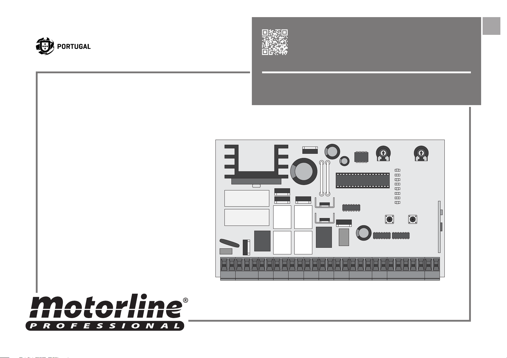
The MC11 is a 24Vdc or 12Vdc electronic central unit for the automation of swing gates, sliding gates and
bollards with radio receiver and built-in battery charger.
• Transformer supply 110V/230Vac 50/60Hz 120W máx.
• Control board supply 20Vac 50/60Hz 120W máx.
• Intermittent output 24Vdc 4W máx.
• Emergency battery input 24Vdc 7A/h máx.
• Engines Output 24Vdc 2 x 50W máx.
• Electric Lock Output 24Vdc 12W máx
• Photocells suplly 24Vdc 3W máx.
• Indication lamp output 12Vdc 3W máx.
• Working Temperature -25C to +55C
• Radio receiver Rolling Code, 433,92 Mhz
• Max TX Code in memory 120 (CODE or CODE PED)
• Control board box dimensions 240 x 190 x 110mm
• Protection grade IP56
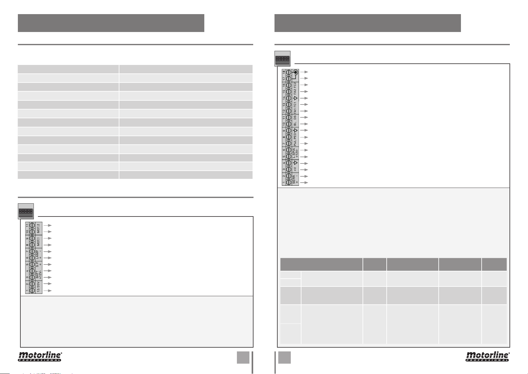
CONNECTOR’S DESCRIPTION
CN1
Output 0V to Motor 2
Output 24Vdc max 50W to Motor 2
Output 0V to Motor 1
Output 24Vdc max 50W to Motor 1
Output 0V to Flashlight
Output 24Vdc 4W to Flashlight
Input 24Vdc 3W max to Solar Panel
Input 0V to Solar Panel or Emergency Battery
Input 24Vdc 1,2/7Ah ou 12Vdc 1,2Ah (only motor TELICA) max to Emergency Battery
Power Input 20Vdc 120W max
Power Input 20Vdc 120W max
03+04 • Emergency battery: In case of power failure, these batteries will supply power to the automation
operation. The number of maneuvers depends on the installed battery and its condition.
05 • Solar panel: Device input to charge the emergency battery.
06+07 • Flashing light: Output for flashlight or courtesy. Its operation can be set in the CODE function of
Extension Menu 2 (page 9B).
CN2
Entrada para pólo quente da Antena
Entrada para massa da Antena
NC input for anti-crushing photo-cells
NC input for anti-crushing photocells
Common line
NC input for interior photocells
NC input for external photocells
NC input for external photocells
NO input for emergency stop devices
Common line
NO input for Pedal Openning button
NO input for Pedal Openning button
Output 0V to Flashlight
Output 12Vdc 3W to Flashlight
Output 0V for Accessories power supply
Output 24Vdc 3W for Accessories power sup-ply
Output 0V for Electric Lock
Output 12V 24Vdc for Electric Lock
01+02 • Electric lock: 24Vdc output with a maximum capacity of 12W.
03+04 • Power supply Accessories: Power supply Accessories: Output 24Vdc with maximum capacity of 3W.
05+06 • Signal lamp: Output 12Vdc with maximum capacity of 3W. The light blinks slowly when the gate is
opening and blinks rapidly when the gate is closing.
07+09 | 08+09 • Pushbutton: NO input for gate activation buttons. The type of operation is defined in the CODE
function of the Extension Menu 1.
09+10 • STOP: NC input for emergency stop devices.
11+14 | 12+14 | 13+14 | 15+14 | 16+14 •
Photocell Circuit:
11 + 14
12 + 14
13 + 14
15 + 14
16 + 14
EXTERNAL PHOTOCELLS
(with closing intervention)
INTERIOR PHOTOCELLS
(with opening intervention)
ANTICRUSHING
PHOTOCELLS
(with opening intervention)
CLOSED
GATE
Without
influence
Do not let
it open
Do not let
it open
GATE IS OPENING OPENED GATE
Without influence Do not let it close.
Stops and stands still
waiting for the photoce-
lls to be restored
Stops and relieves
slightly. If the photocells
are restored, the gate
is stopped waiting for a
new order to continue
opening.
Without influence
Do not let it close. If
the photocells have
been restored, the
gate is stopped waiting for a new order
to close.
GATE IS
CLOSING
Stop and
reverse
Without
influence
Without
influence
A B
ENEN
 Loading...