

Motorline MBM8, MBM11 User Manual
MBM8 / MBM11- Barriers
Installer and User’s manual
v2.0
REV. 01/2014
00. CONTENT
INDEX STANDARDS TO FOLLOW
01.SAFETY INSTRUCTIONS
00. CONTENT
▷ index | page 01.A
01. SAFETY INSTRUCTIONS
▷ standards to follow | page 01.B
02. PACKAGE
▷ inside package | page 02.A
03. THE AUTOMATISM
▷ technical specifications | page 02.B
▷ opening / closing | page 03.A
04. INSTALATION
▷ installation site preparation | page 03.B
▷ barrier’s fixation | page 04.B
▷ boom assembly | page 05.A
▷ boom support installation | page 05.A
▷ top cover removal | page 05.B
▷ spring adjustment | page 06.A
▷ boom leveling | page 07.A
▷ limit-switch | page 07.B
05. CONTROL BOARD MC15 CONFIGURATION
▷ checking limit-switches connections | page 08.A
▷ barrier’s course configuration | page 08.B
▷ transmitters configuration | page 09.A
▷ pause time configuration | page 09.A
▷ condominium function and potenciometers | page 09.B
06. TROUBLESHOOTING
▷ final consumers instructions | page 10.A
▷ specialized technicians intructions | page 10.A
07. COMPONENTS TEST
▷ connections scheme | page 11.A
08. MAINTENANCE
▷ maintenance | page 11.B
09. CONTROL BOARD CONNECTIONS
▷ MOTORLINE MC15 control board | page 12.A
ATTENTION:
▷ To ensure the people’s safety, it is important that you read all the following
instructions.Incorrect installation or incorrect use of the product can cause physical
injury and material damage.
▷ Keep these instructions in a safe place for future reference.
▷ This product was designed and produced strictly for the use indicated in this
manual. Any other use, not expressly indicated here, could compromise the good
condition/operation of the product and/or be a source of danger.
▷ ELECTROCELOS SA is not responsible for the improper use of the product,
or other use than that for which it was designed.
▷
ELECTROCELOS SA is not responsible if safety standards were not taken into
account when installing the equipment, or for any deformation that may occur to it.
▷ ELECTROCELOS SA is not responsible for the safety and proper operation
when using components not sold by them.
▷ Do not make any modifications to the operator components and / or their
accessories.
▷ Beore installation unplug the automatism from the source of power.
▷ The installer must inform the client how to handle the product in case of
emergency and provide this manual to user.
▷ Keep remote controls away from children, to prevent the automated
system from being activated involuntarily.
▷ The customer shall not, under any circumstances, attempt to repair or tune
the operator .Must call qualified technician only.
▷ Connect the automatism to a 230V plug with ground wire.
▷ Automatism for outdoor use.
01.A 01.B
02. PACKAGE
INSIDE PACKAGE TECHNICAL SPECIFICATIONS
03.AUTOMATISM
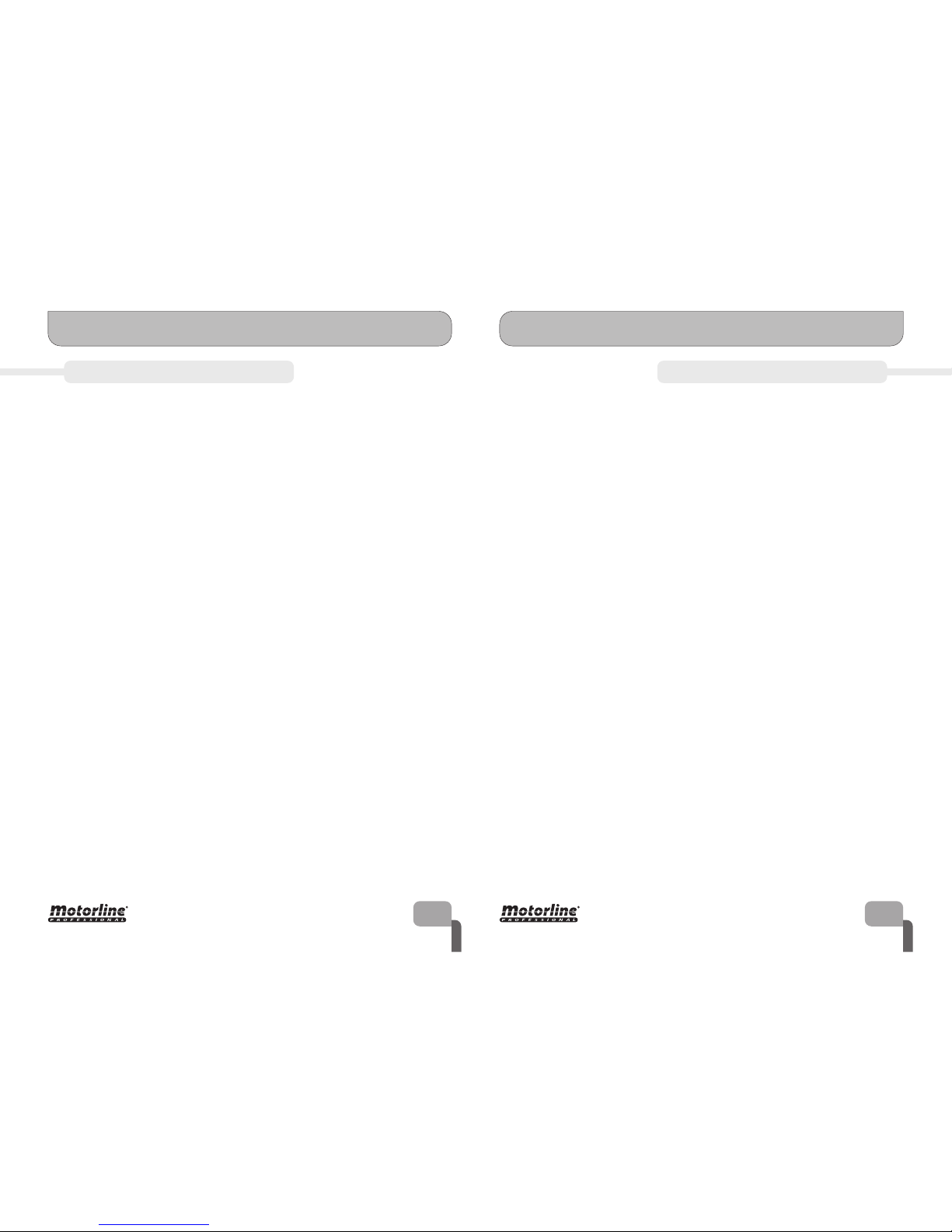
Inside the package you will find the following components:
▷ 01 electromechanical barrier
▷ 01 MC15 control board
▷ 02 4channel MX4SP transmitter
▷ 01 aluminium boom
▷ 01 boom support
▷ 01 MF3 external photocells set
▷ 02 fastening metal plates
02.A 02.B
Electromechanical barrier
Alluminium
boom
Boom
support
Boom
support
fastening
screws
Boom
fastening
screws
Boom
cover
Control
board
M16 bolts
with
bushings
Fastening
metal
plates
Boom fastening
metal plate
User’s
manual
MX4SP
Transmitter
MF3
photocells
▷ 01 boom fastening metal plate
▷ 04 M16 bolts with bushings
▷ 04 boom fastening screws
▷ 02 boom support fastening screws
▷ 01 boom cover
▷ 01 installer and user’s manual
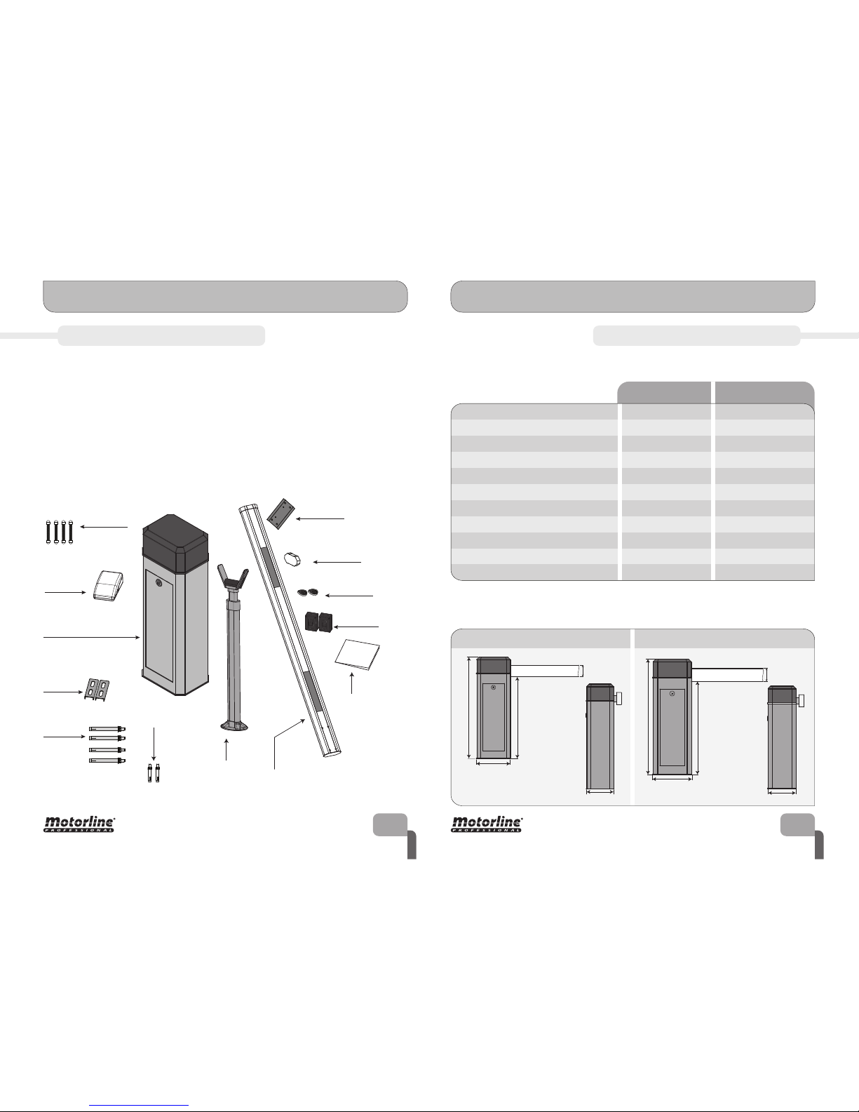
The specifications of the MBM8 and MBM11 barriers are:
The main dimensions of the MBM8 and MBM11 barrier are:
▷ Barrier’s Power Supply
▷ Motor’s Voltage
▷Power
▷ Working temperature
▷
▷ Working frequency
▷ RPM
▷ Noise level
▷ Opening / Closing time
▷ Current
AC 230V 50/60Hz
AC 230V
180W
-45°C to 65°C
120°C
Intense
2800 RPM
<60 db
6 s
1A
AC 230V 50/60Hz
AC 230V
300W
-45°C to 65°C
140°C
Intense
▷ Protection level IP55 IP55
480 RPM
<70 db
11 s
2A
Thermal protection
MBM8 MBM11
mm
mm
mm
mm
mm
MBM8 MBM11
mm
mm
mm
mm
mm

INSTALLATION SITE PREPARATION
03. AUTOMATISM
OPENING / CLOSING
04. INSTALLATION
03.A 03.B
It’s important that this order of installation is respected!
Otherwise we can’t assure the correct installation of the barrier and it may
not work properly.
1▷ Create a foundation in
cement on the soil. The dimen-
sions on the side image are the
minimum to maintain, so they
can be superiors but never
inferiors.
You must leave one or more
tubes for the cables of the
dierent components to pass
through the foundation to the
barrier (photocells, wall starts,
key selectors, etc).
In case of power failure, the barrier is equipped with a manual unlocking and locking
system. Follow the instructions bellow to unlock or lock the barrier.
1▷ Open the door using the key supplied
with the barrier. Rotate the key to unlock
the door and pull it towards outside.
On the interior, you will have access to the
unlocking system.
2▷ The unlocking is made by rotating the
disc at the bottom of the motor, highlight-
ed/shaded on the image on the side.
To open or close you must try to rotate the
disk clockwise or counter-clockwise, that
depending on the orientation of the barrier
(right or left) will open or close the boom.
20mm
(height of
foundation
above soil)
500 mm
(total height
of
foundation)
350mm
450mm
20mm
(height of
foundation
above soil)
500 mm
(total height
of
foundation)
400mm
550mm
Foundation in cement for MBM8 barrier
Foundation in cement for MBM11 barrier
 Loading...