

Motorline KVM 25 Operation Manual And Installation Instructions

KVM 25
OPERATION MANUAL / INSTALLER
v1.0
REV. 06/2014
00. CONTENTS
▷ INDEX STANDARDS TO FOLLOW ◁
01. SAFETY INSTRUCTIONS
00. CONTENTS
index | page 01.A
01. SAFETY INSTRUCTIONS
standards to follow | page 01.B
02. THE PACKAGE
inside the package | page 02.A
03. THE AUTOMATISM
Lock / Unlock | page 02.B
technical specifications | page 03.A
04. INSTALLATION
pre-installation info | page 03.B
automatism installation | page 04.A
installation map | page 05.B
05. PROGRAMMING
programming the limit switches | page 06.A
description | page 07.A
programming dip switches | page 07.A
adjusting potentiometers | page 07.B
programming transmitter | page 07.B
reset control board’s memory | page 07.B
06. CONNECTION SCHEME
connecting components to the control board | page 08.A
ATTENTION:
▷ To ensure the safety of people, it is important that you read all the following
instructions.Incorrect installation or incorrect use of the product can cause physical
injury and material damage.
▷ Keep these instructions in a safe place for future reference.
▷ This product was designed and produced strictly for the use indicated in this
manual. Any other use, not expressly indicated here, could compromise the good
condition/operation of the product and/or be a source of danger.
▷ ELECTROCELOS SA is not responsible for the improper use of the product,
or other use than that for which it was designed.
▷ ELECTROCELOS SA is not responsible if safety standards were not taken
into account when installing the equipment, or for any deformation that may occur to
it.
▷ ELECTROCELOS SA is not responsible for the safety and proper operation
when using components not sold by them.
▷ Do not make any modifications to the operator components and / or their
accessories.
▷ Beore installation unplug the automatism from the source of power.
▷ The installer must inform the client how to handle the product in case of
emergency and provide this manual to user.
▷ Keep remote controls away from children, to prevent the automated
system from being activated involuntarily.
▷ The customer shall not, under any circumstances, attempt to repair or tune
the operator .Must call qualified technician only.
▷ Connect the automatism to a 230V plug with ground wire.
▷ Operator for outdoor and indoor use.
01.A 01.B
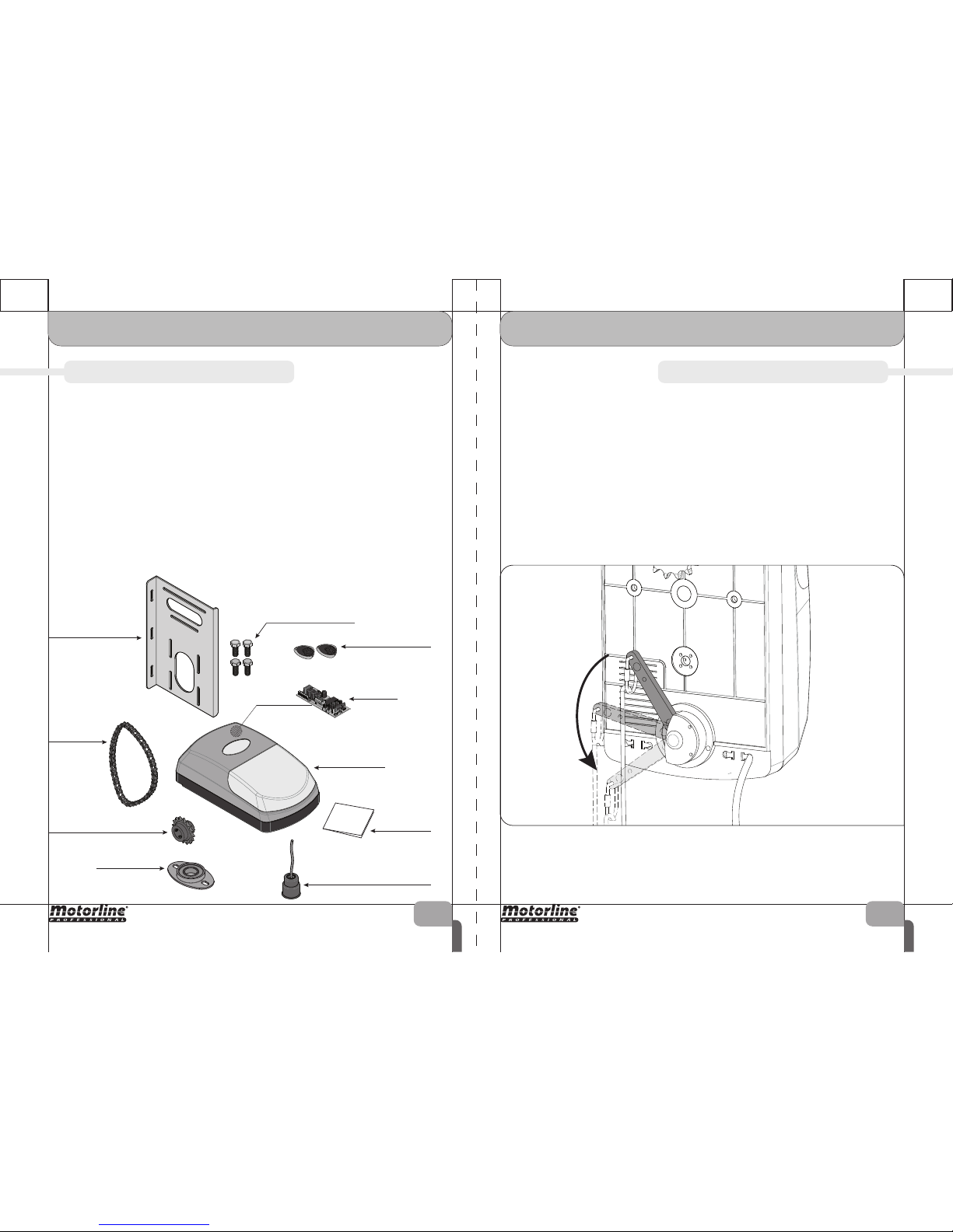
Mounting plate
02. THE PACKAGE
▷ INSIDE THE PACKAGE LOCK / UNLOCK ◁
03. THE AUTOMATISM
Inside the package you will find the following components:
▷
01 automatism KVM25
▷
01 control board (inside motor)
▷
02 four channel transmitters MX4SP
▷
01 mounting plate
▷
01 chain
▷
01 pinion for Ø25mm shaft
▷
01 bearing bracket
▷
04 fixing screws
▷
01 unlocking cord
▷
01 user manual
02.A 02.B
The automatism unlock function allows the user to open and close the gate manually,
without having to remove the motor from the installation site.
This funcionality is specially important in emergency cases and/or power cuts.
To lock or unlock the automatism just pull down the lever as shown in the following
image.
The lever has a spring that will bring it up to the starting point.
Each time you pull the lever down and rise completely, you will unlock or lock the
automatism.
When pulling down, a small sound of gears engaging means that the lock/unlock was
successfully performed.
Fixing screws
Bearing bracket
Pinion for shaft
Chain
Transmitters MX4SP
Control Board
Automatism KVM25
User
manual
unlocking cord
 Loading...