

Page 1

Operation
Maintenance
Installation
Warranty
Manual
8M0130831 1117 eng
Xi3 Wireless Edition
© 2017 Mercury Marine
Page 2

eng
Page 3

ORIGINAL LANGUAGE INSTRUCTIONS
FCC and IC Compliance Statement
Xi SERIES WIRELESS FOOT PEDAL FCC ID ‑ MVU09291
Xi SERIES WIRELESS REMOTE FCC ID ‑ MVU09305
IC: 6094A‑09291, 6094A‑09305
This device complies with part 15 of the FCC Rules. Operation is subject to the
following two conditions:
1. This device may not cause harmful interference.
2. This device must accept any interference received including interference
that may cause undesired operation.
This device complies with FCC Rules.
Changes or modifications not expressly approved by the party responsible for
compliance could void the user's authority to operate the equipment.
This device complies with Industry Canada license‑exempt RSS standard(s).
Operation is subject to the following two conditions: (1) this device may not
cause interference, and (2) this device must accept any interference, including
interference that may cause undesired operation of the device.
Le présent appareil est conforme aux CNR d'Industrie Canada applicables aux
appareils radio exempts de licence. L'exploitation est autorisée aux deux
conditions suivantes: (1) l'appareil ne doit pas produire de brouillage, et (2)
l'utilisateur de l'appareil doit accepter tout brouillage radioélectrique subi, même
si le brouillage est susceptible d'en compromettre le fonctionnement.
Simplified EU DoC
Hereby, Attwood Corporation declares that the radio equipment type, Xi3
Trolling Motor System, is in compliance with Directive 2014/53/EU. – The full
text of the EU declaration of conformity is available at the following internet
address: http://www.motorguide.com/support/literature
Important Operator Information
!
ISO 7000‑0434B ‑ Caution symbol
Consult this documentation in all cases where this symbol appears. This
symbol is used to inform you of any potential HAZARD or actions that
require your attention.
Use of this equipment in a manner other than that specified by Attwood
Corporation may compromise the design integrity and become unsafe.
WARNING: This equipment is not intended for use in explosive environments.
ADVERTENCIA: Este equipo no está diseñado para uso en atmósferas
explosivas.
eng i
Page 4

AVVERTIMENTO: Questa apparechiatura non è inteso per l'uso in ambienti
esplosivi.
WARNUNG: Das Ausrüstung darf in einer explosiven Umgebung NICHT
verwendet werden.
ADVERTISSEMENT: Cet équipement n'est pas prévu pour une utilisation das
des environments explosifs.
Thank You
Thank you for purchasing a MotorGuide Xi3 Wireless Trolling Motor.
The Xi3 is designed and engineered to deliver the performance that anglers
expect: quiet operation, reliability, and precise control. We’re confident that the
Xi3 will enhance your fishing experience and we appreciate that you chose
MotorGuide.
Please take a moment to register your new Xi3 at www.motorguide.com—or
complete and mail the enclosed Warranty Registration Card.
Warranty Message
The product you have purchased comes with a Limited Warranty from
MotorGuide. The terms of the policy are set forth in the Warranty Information
section of this manual. The policy statement contains a description of the
duration of coverage, important disclaimers and limitations of damages,
and other related information. Please review this important information.
The description and specifications contained herein were in effect at the time
this manual was approved for printing. MotorGuide, whose policy is one of
continued improvement, reserves the right to discontinue models at any time, to
change specifications, designs, methods, or procedures without notice and
without incurring obligation.
MotorGuide, Lowell, Michigan U.S.A.
Mercury Marine
Eagle and Lowrance are registered trademarks of Navico Inc. Garmin is a
registered trademark of Garmin Ltd. Humminbird is a registered trademark of
Johnson Outdoors Marine Electronics, Inc. Vexilar is a registered trademark of
Vexilar, Inc.
Copyright and Trademark Information
© MERCURY MARINE. All rights reserved. Reproduction in whole or in
part without permission is prohibited.
Alpha, Axius, Bravo One, Bravo Two, Bravo Three, Circle M with Waves Logo,
K‑planes, Mariner, MerCathode, MerCruiser, Mercury, Mercury with Waves
Logo, Mercury Marine, Mercury Precision Parts, Mercury Propellers, Mercury
Racing, MotorGuide, OptiMax, Quicksilver, SeaCore, Skyhook, SmartCraft,
Sport‑Jet, Verado, VesselView, Zero Effort, Zeus, #1 On the Water and We're
Driven to win are registered trademarks of Brunswick Corporation. Pro XS is a
trademark of Brunswick Corporation. Mercury Product Protection is a registered
service mark of Brunswick Corporation.
ii eng
Page 5

Warranty Information
MotorGuide Two Year Limited Warranty............................................................ 1
General Information and Component Identification
Component Identification.................................................................................... 4
Recording the Serial Number............................................................................. 5
Product Registration........................................................................................... 5
Boater's Responsibilities..................................................................................... 5
Protecting People in the Water........................................................................... 6
Passenger Safety Message................................................................................ 6
Safe Boating Suggestions.................................................................................. 6
Product Installation, Wiring, and Battery Information
Installing the Trolling Motor.................................................................................8
Recommended Practice and Procedures......................................................... 11
Battery Recommendations............................................................................... 11
Battery Precautions.......................................................................................... 12
Wire Color Code Abbreviations........................................................................ 13
Battery Connection........................................................................................... 13
Wire and Cable Routing....................................................................................15
Activating the Handheld Remote...................................................................... 15
Connecting the Sonar Display to the Trolling Motor......................................... 16
Reducing Sonar Transducer Interference.........................................................17
Trolling Motor Operation
Status Indicator Light Identification................................................................... 19
Stowing and Deploying the Trolling Motor........................................................ 19
Adjusting the Motor Depth................................................................................ 23
Handheld Remote Operation............................................................................ 25
eng iii
Page 6

Maintenance and Storage
Trolling Motor Care........................................................................................... 27
Inspection and Maintenance Schedule............................................................. 27
Storage Preparation..........................................................................................29
Battery Inspection............................................................................................. 29
Corrosion Control Anode (Saltwater Models)................................................... 29
Propeller Replacement..................................................................................... 30
Owner Service Assistance
Troubleshooting................................................................................................ 33
Troubleshooting the Handheld Remote............................................................ 36
Service Assistance........................................................................................... 38
Mercury Marine Service Offices........................................................................ 38
iv eng
Page 7

WARRANTY INFORMATION
MotorGuide Two Year Limited Warranty
KEEP YOUR ORIGINAL PURCHASE RECEIPT OR BILL OF SALE.
1. For recreational use customers, MotorGuide electric trolling motors are
warranted to the original retail purchaser to be free from defects in
material or workmanship for a period of two years from the date of
purchase.
2. To obtain warranty service, the purchaser should deliver or return the unit
(postage prepaid and insured) to any MotorGuide authorized service
dealer. DO NOT RETURN TO PLACE OF PURCHASE unless they are
an authorized service center. Products returned by mail should be
carefully packaged and include a note describing the nature of the
problem and/or service requested, customer address, and phone number.
A copy of the receipt, bill of sale, registration verification or other proof of
purchase is required with the return of the product for warranty
consideration. Warranty claims will not be accepted without presentation
of purchase receipt for the trolling motor, other verification of registration,
or bill of sale for a boat package.
3. MotorGuide, at its discretion, will repair or replace items covered under
the terms of this warranty. Neither MotorGuide nor MotorGuide service
dealers are responsible for damages to MotorGuide products due to
repairs performed by anyone other than an authorized MotorGuide
service dealer. Neither MotorGuide nor Attwood is responsible for failure
or damage caused by improper installation, set‑up, preparation, or
previous service or repair errors.
4. For commercial use and government use customers, MotorGuide electric
trolling motors are warranted to the original retail purchaser to be free
from defects in material or workmanship for one (1) year. Commercial use
is defined as any work or employment‑related use of the product, or any
use of the product which generates income, for any part of the warranty
period, even if the product is only occasionally used for such purpose
such as rental fleets, guides, fish camps or similar operations. Warranty is
not transferable to any subsequent purchaser. The Mercury Product
Protection plan is not available to commercial use or government use
customers.
5. MotorGuide Composite Shaft Limited Lifetime Warranty. MotorGuide
composite shafts are warranted to the original retail purchaser to be free
of defects in material or workmanship for the lifetime of the original
purchaser. MotorGuide will provide a new composite shaft at no cost for
any composite shaft which contains a defect in material or workmanship.
The installation costs are the sole responsibility of the purchaser.
eng 1
Page 8

WARRANTY INFORMATION
6. Warranty coverage is available to customers that purchase from an
authorized dealer or retailer that is authorized by MotorGuide Marine to
distribute the product in the country in which the sale occurred. Warranty
coverage and duration varies by the country in which the owner resides.
This Limited Warranty begins on the date the product is first sold to a
purchaser or the date on which the product is first put into service,
whichever occurs first. MotorGuide accessories are covered by this
Limited Warranty for a coverage period of one (1) year from the date of
retail sale. The repair or replacement of parts, or the performance of
service under this warranty, does not extend the life of this warranty
beyond its original expiration date. Promotional warranties are not
included in this statement and coverage may vary by promotion. Product
either sold or put into service more than six years from date of
manufacture is excluded from warranty coverage.
7. This warranty does not apply to normal worn parts, for example, worn
cables, adjustments, or product damage due to: 1) neglect, lack of
maintenance, accident, abnormal operation or improper installation or
service; 2) abuse, such as, bent metal columns, bent armature shafts,
broken control cables, etc., accidents, modifications, misuse, excessive
wear or damage caused by an owner’s failure to provide reasonable and
necessary installation or care; 3) use of an accessory or part not
manufactured by MotorGuide or Attwood; 4) alteration or removal of parts;
5) opening the lower unit (motor); 6) opening the transmission by anyone
other than an authorized MotorGuide service center will void this
warranty.
8. We reserve the right to improve the design of any trolling motor without
assuming any obligation to modify any trolling motor previously
manufactured.
9. All serialized "Service‑Repair" trolling motors receive a (1) one year
warranty. Non‑serialized "Service‑Repair" electric trolling motors are NOT
warranted. "Service‑Repair" motor denotes a trolling motor sold by
MotorGuide that may be used, but has been inspected and may have had
minor repairs. Original retail purchaser of a "Service‑Repair" motor is the
first purchaser of the motor after it is denoted as "Service‑Repair."
"Service‑Repair" motors have a blue sticker on the battery cable and box
denoting "Manufacturer Certified Service‑Repair Motor."
10. This warranty will not apply to: 1) haul‑out, launch, towing and storage,
transportation charges and/or travel time, telephone or rental charges of
any type, inconvenience, or loss of time or income, or other consequential
damages; or 2) removal or replacement of boat partitions or material
because of boat design for necessary access to the Product; or 3)
disconnection and reconnection of hard‑wired trolling motors.
11. TERMINATION OF COVERAGE: Warranty coverage may be terminated
for repossessed product, or product purchased at auction, from a salvage
yard, from a liquidator, from an insurance company, from unauthorized
marine dealers or boatbuilders, or other third party entities.
2 eng
Page 9

WARRANTY INFORMATION
12. ALL INCIDENTAL OR CONSEQUENTIAL DAMAGES ARE EXCLUDED
FROM THIS WARRANTY, WARRANTIES OF MERCHANTABILITY AND
FITNESS ARE EXCLUDED FROM THIS WARRANTY, IMPLIED
WARRANTIES ARE LIMITED TO THE LIFE OF THIS WARRANTY.
SOME STATES DO NOT ALLOW LIMITATIONS ON HOW LONG AN
IMPLIED WARRANTY LASTS OR THE EXCLUSION OR LIMITATION
OF INCIDENTAL OR CONSEQUENTIAL DAMAGES, SO THE ABOVE
LIMITATIONS OR EXCLUSIONS MAY NOT APPLY TO YOU. THIS
WARRANTY GIVES YOU SPECIFIC LEGAL RIGHTS, AND YOU MAY
ALSO HAVE OTHER LEGAL RIGHTS WHICH MAY VARY FROM
STATE TO STATE.
For Your Records:
Model Number _______________________________
Serial Number _______________________________
eng 3
Page 10
64267
b
g
h
i
j
l
f
d
a
m
c
e
k
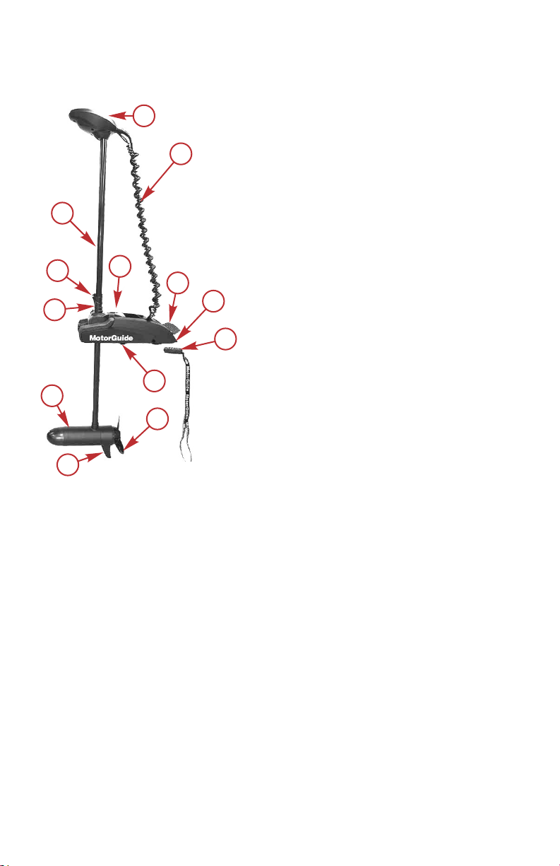
GENERAL INFORMATION AND COMPONENT
IDENTIFICATION
Component Identification
a - Head
b - Curly cable
c - Foot release lever
d - Battery cables (hidden)
e - Handheld wireless remote
f - Deck mount
g - Propeller
h - Skeg
i - Lower unit (motor)
j - Depth collar
k - Depth collar knob
l - Composite column
m - Steering transmission
4 eng
Page 11
a
b
64677
GENERAL INFORMATION AND COMPONENT
IDENTIFICATION
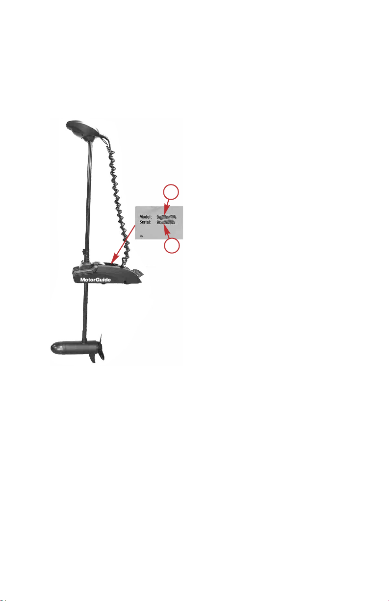
Recording the Serial Number
It is important to record the serial number and model number for future
reference. The serial number tags are located on the trolling motor as shown.
Record the serial number and the model number in the space provided in the
Warranty Information section of this manual.
a - Model identification number
b - Serial number
Product Registration
For warranty purposes, please register your MotorGuide trolling motor by
completing the enclosed warranty card or by visiting www.motorguide.com.
Boater's Responsibilities
The operator (driver) is responsible for the correct and safe operation of the
boat and safety of its occupants and general public. It is strongly recommended
that each operator (driver) read and understand this entire manual before
operating the trolling motor.
Be sure at least one additional person on board is instructed in the basic
operation of the trolling motor in case the driver is unable to operate the boat.
eng 5
Page 12
21604
GENERAL INFORMATION AND COMPONENT
IDENTIFICATION
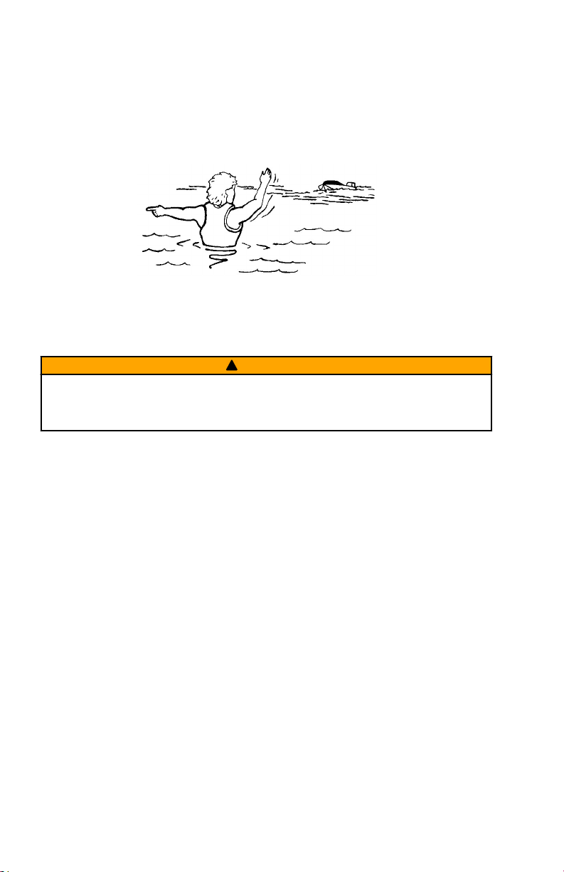
Protecting People in the Water
WHILE YOU ARE TROLLING
It is difficult for a person in the water to take quick action to avoid a boat
heading in their direction, even at slow speeds.
Always slow down and exercise extreme caution any time you are boating in an
area where there might be people in the water.
WHILE THE BOAT IS STATIONARY
WARNING
!
A spinning propeller, a moving boat, or any solid device attached to the boat
can cause serious injury or death to swimmers. Stop the trolling motor
immediately whenever anyone in the water is near your boat.
Unplug the trolling motor before allowing people to swim or be in the water near
your boat.
Passenger Safety Message
Whenever the boat is in motion, observe the location of all passengers. A
sudden reduction in boat speed, such as a sharp change of boat direction,
could throw them off the boat.
Safe Boating Suggestions
In order to safely enjoy the waterways, familiarize yourself with local and other
governmental boating regulations and restrictions, and consider the following
suggestions.
Use flotation devices. It is the law to have an approved personal flotation
device of suitable size for each person aboard and have it readily accessible.
Do not overload your boat. Most boats are rated and certified for maximum
load (weight) capacities, refer to your boat capacity plate. If in doubt, contact
your dealer or the boat's manufacturer.
Perform safety checks and required maintenance. Follow a regular
schedule and ensure all repairs are made properly.
Never be under the influence of alcohol or drugs while boating (it is the
law). Alcohol or drug use impairs your judgment and greatly reduces your
ability to react quickly.
6 eng
Page 13

GENERAL INFORMATION AND COMPONENT
IDENTIFICATION
Passenger boarding. Stop the trolling motor whenever passengers are
boarding or unloading.
Be alert. The operator of the boat is responsible by law to maintain a proper
lookout by sight and hearing. The operator must have an unobstructed view
particularly to the front. No passengers, load, or fishing seats should block the
operators view when operating the boat.
Underwater hazards. Reduce speed and proceed with caution whenever
navigating in shallow water.
Tripping hazards. To avoid a trip hazard, route all cables and wiring neatly
and out of the way.
Report accidents. Boat operators are required by law to file a Boating
Accident Report with their state boating law enforcement agency when their
boat is involved in certain boating accidents. A boating accident must be
reported if 1) there is loss of life or probable loss of life, 2) there is personal
injury requiring medical treatment beyond first aid, 3) there is damage to boats
or other property where the damage value exceeds $500.00 or 4) there is
complete loss of the boat. Seek further assistance from local law enforcement.
eng 7
Page 14
a
a
b
64678
PRODUCT INSTALLATION, WIRING, AND BATTERY
INFORMATION
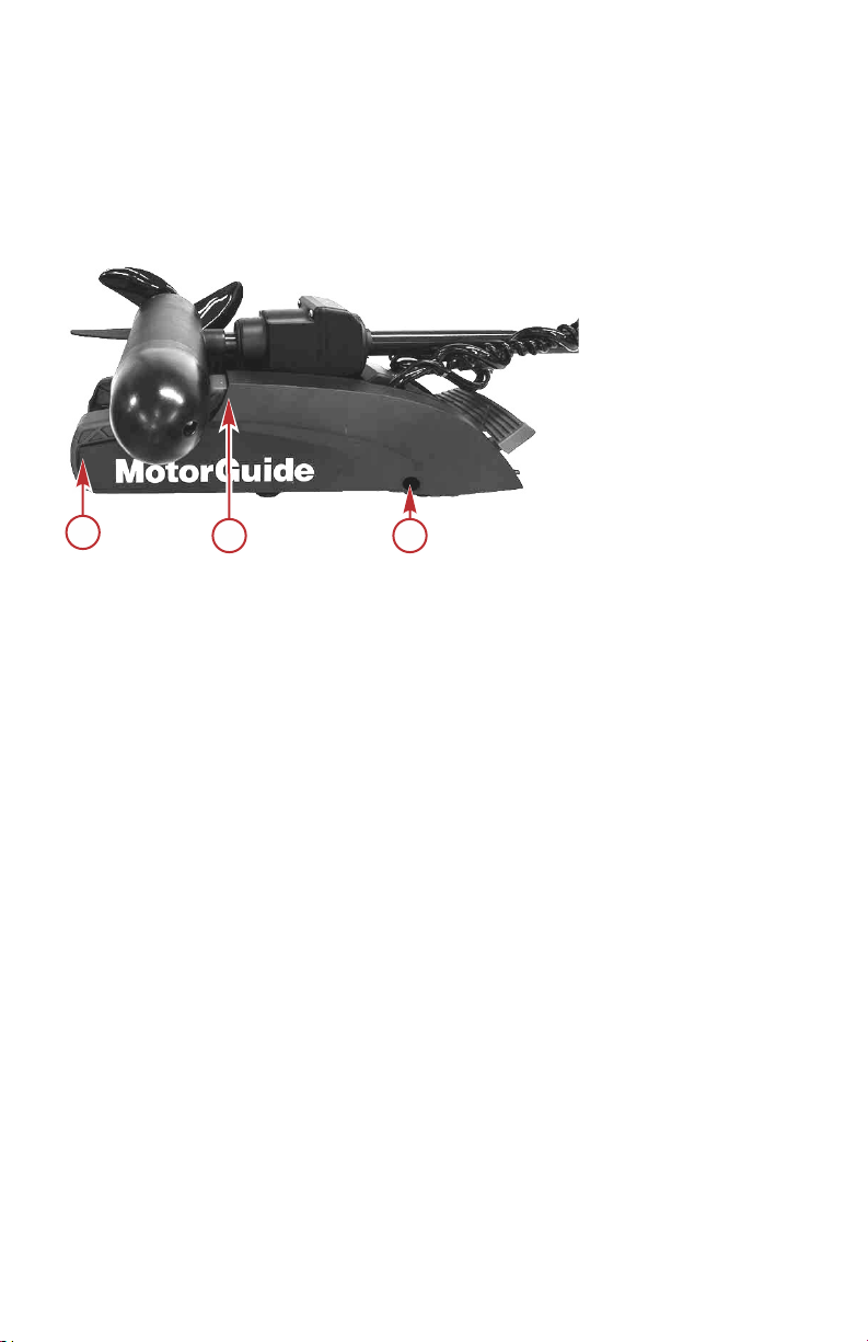
Installing the Trolling Motor
1. Remove the side panel screw from each side of the deck mount. Gently
pull the side panels away from the deck mount, taking care not to damage
the locating tabs, and remove the side panels from both sides of the
trolling motor.
a - Locating tabs
b - Side panel screw
2. If you are replacing an existing MotorGuide or competitive brand trolling
motor on your current boat, check if the existing mounting holes align with
the new deck mount before drilling new holes. Ensure that the mounting
location meets the requirements listed in Step 4.
3. If new holes are not required to mount the trolling motor, skip ahead to
Step 7.
4. Carefully select an appropriate area on the deck of the boat close to the
centerline to install the trolling motor. Ensure that the forward mounting
bolts will not penetrate the hull. Have an assistant hold the trolling motor
in position while the mounting location is being selected.
IMPORTANT: The mounting position must be tested in the stowed and
deployed positions before drilling the mounting holes.
IMPORTANT: Ensure that the head does not protrude beyond the beam of the
boat when in the stowed position.
8 eng
Page 15

53447
64680
PRODUCT INSTALLATION, WIRING, AND BATTERY
INFORMATION
IMPORTANT: A minimum clearance of 13 mm (0.5 in.) is required between
the motor column and the rub rail on the boat when the trolling motor is
deployed.
5. Place the trolling motor onto the deck of the boat at the selected location
in the stowed position. Use the deck mounting bracket as a template and
mark the location of the mounting holes.
IMPORTANT: Four mounting holes (two on each side) are required to securely
mount the trolling motor. There are seven mounting hole positions to choose
from on each side of the deck mounting bracket. Choose two hole positions on
each side that work the best with your boat configuration.
IMPORTANT: Select mounting hole locations as far apart as practical on each
side of the deck mounting bracket for the most secure mounting.
Mounting hole locations—same on both sides
6. Drill the mounting holes with a 8 mm (5/16 in.) drill bit. Remove any
debris.
IMPORTANT: To help prevent cracking on fiberglass decks, use a countersink
bit or a larger drill bit to countersink the mounting holes.
7. Align the deck mounting bracket to the holes in the deck. On fiberglass
boats with no carpet where the motor is being installed, install the rubber
isolators between the boat deck and the deck mounting bracket. Install
three stainless steel mounting bolts through the mounting holes on one
side of the deck mounting bracket. Install a washer and a nylock nut onto
each bolt, but do not tighten them at this time.
eng 9
Page 16
a
b
c
d
e
f
a
b
d
e
f
g
52406
PRODUCT INSTALLATION, WIRING, AND BATTERY
INFORMATION
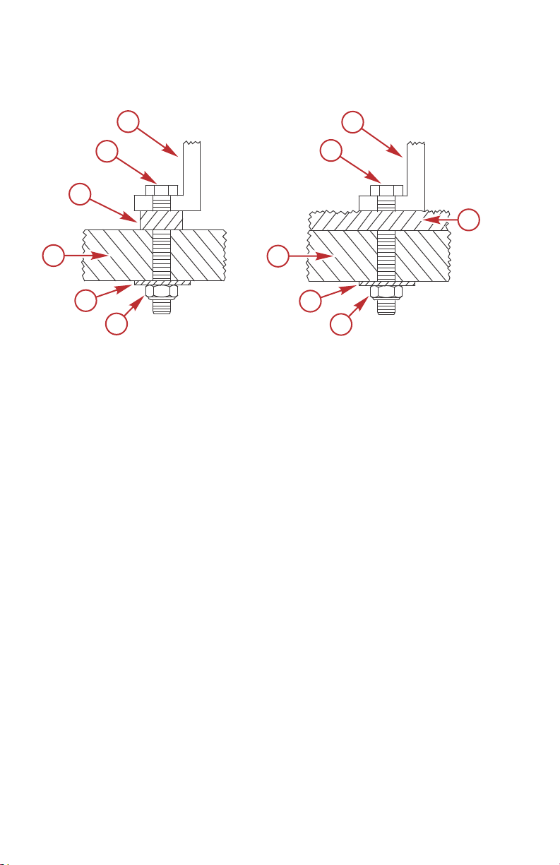
NOTE: If the trolling motor is being mounted to a carpeted boat deck, the
rubber isolators are not required.
a - Deck mounting bracket
b - Mounting bolt
c - Rubber isolator
d - Deck
e - Washer
f - Stainless steel nylock nut
g - Carpet
8. Align the trolling motor with the mounting holes in the deck. Hold the
mounting screws securely with a 7/16 in. wrench while using a wrench or
socket to tighten the nylock nuts on both sides of the deck mounting
bracket from under the deck.
10 eng
Page 17

a
a
b
64678
PRODUCT INSTALLATION, WIRING, AND BATTERY
INFORMATION
9. Install the side panels (deckets) onto the trolling motor by inserting the
tabbed end into the lower unit cradle bracket slot, taking care not to
damage the locating tabs. Install the side panel screw.
a - Locating tabs
b - Side panel screw
Recommended Practice and Procedures
IMPORTANT: Unplug the trolling motor after each use and when charging the
battery.
• Do not use the main engine battery to power the trolling motor. Use a
dedicated trolling motor battery or battery bank.
• Ensure that the batteries are enclosed and secured within a battery box to
prevent accidental shorting of the battery terminals.
• Route the trolling motor wires on the opposite side of the boat from other
boat wiring.
• Ensure the positive and negative wires are bound to each other.
• Connect boat accessories directly to the main engine battery.
• Do not charge the trolling motor batteries while the trolling motor is in the
deployed (down) position.
Battery Recommendations
• Use 12‑volt, deep cycle marine batteries. The number of batteries
required varies according to the model of your trolling motor. Refer to
Battery Connection.
• As a general rule, deep cycle batteries with a higher amp‑hour rating or
reserve capacity rating will provide longer run times and better
performance.
• Install a manual reset circuit breaker in line with the trolling motor positive
leads within 1.8 m (6 ft) of the batteries. These can be purchased from
your local MotorGuide retailer or from www.motorguide.com.
eng 11
Page 18
PRODUCT INSTALLATION, WIRING, AND BATTERY
INFORMATION
• Do not extend the included 10‑gauge battery cables more than 1.8 m (6 ft)
for a total of 3 m (10 ft). If longer battery cables are required, MotorGuide
offers accessory 8 mm² (8‑gauge) battery cables.
• Use stainless steel nylock nuts to secure the battery cables to their
terminals. Using stainless steel wing nuts to secure the battery cables can
cause loose connections.
• Do not power any depth sounders or fish finders from the trolling motor
battery. Connecting electronic equipment to the trolling motor batteries
can cause electrical interference. Any depth sounders or fish finders must
be powered from the engine starting or accessory battery.
Recommended MotorGuide Accessory Description
8‑gauge battery cable and terminals with 50‑amp manual reset circuit breaker
50‑amp manual reset circuit breaker
60‑amp manual reset circuit breaker
Battery Precautions
WARNING
!
An operating or charging battery produces gas that can ignite and explode,
spraying out sulfuric acid, which can cause severe burns. Ventilate the area
around the battery and wear protective equipment when handling or servicing
batteries.
When charging batteries, an explosive gas mixture forms in each cell. Part of
this gas escapes through holes in the vent plugs and may form an explosive
atmosphere around the battery if ventilation is poor. This explosive gas may
remain in or around the battery for several hours after it has been charged.
Sparks or flames can ignite this gas and cause an internal explosion, which
may shatter the battery.
The following precautions should be observed to prevent an explosion:
1. Keep flames away and do not smoke near batteries being charged or
which have been charged recently.
2. Do not disconnect the battery cables while the trolling motor is operating,
because a spark usually occurs at the point where a live circuit is broken.
Always use care to prevent reverse polarization when connecting or
disconnecting cable clamps on chargers. Poor connections are a common
cause of electrical arcs, which cause explosions.
3. Do not reverse the polarity of battery terminal to cable connections.
12 eng
Page 19
PRODUCT INSTALLATION, WIRING, AND BATTERY
INFORMATION
Wire Color Code Abbreviations
Wire Color Abbreviations
BLK Black
BRN Brown GRY or GRA Gray
GRN Green ORN or ORG Orange
PNK Pink PPL or PUR Purple
RED Red TAN Tan
WHT White YEL Yellow
LT or LIT Light DK or DRK Dark
Battery Connection
WARNING
!
Before working around electrical system components, disconnect the battery
cables from the battery to prevent injury or damage to the electrical system
due to an accidental short circuit.
!
CAUTION
Disconnecting or connecting the battery cables in the incorrect order can
cause injury from electrical shock or can damage the electrical system.
Always disconnect the negative (‑) battery cable first and connect it last.
BLU Blue
NOTICE
Failure to operate the trolling motor within the recommended voltage
specifications can cause product damage. Do not exceed the maximum
supply voltage.
IMPORTANT: Refer to the decal on the head of the trolling motor to determine
the voltage requirements of your trolling motor.
12-VOLT BATTERY CONNECTION
1. Install a 50‑amp (good) or 60‑amp (best) manual reset circuit breaker in
line with the trolling motor power cable positive (+) lead and the trolling
motor battery positive (+) terminal.
2. Connect the positive (+) trolling motor lead to the positive (+) trolling
motor battery terminal.
eng 13
Page 20
RED
BLACK
abc
64893
PRODUCT INSTALLATION, WIRING, AND BATTERY
INFORMATION
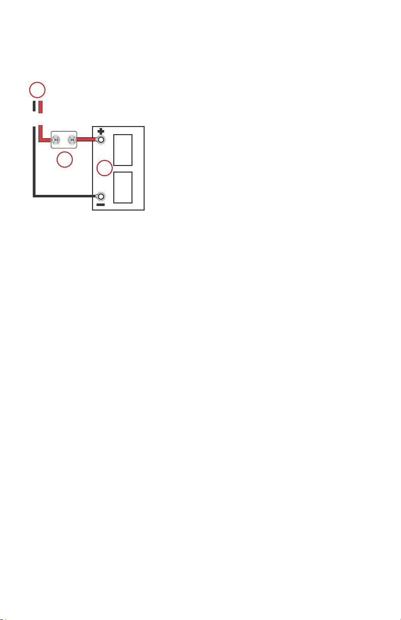
3. Connect the negative (–) trolling motor lead to the negative (–) trolling
motor battery terminal.
12–volt battery connection
a - Power cables to trolling motor
b - Manual reset circuit breaker
c - Trolling motor battery
24-VOLT BATTERY CONNECTION
1. Install a 50‑amp (good) or 60‑amp (best) manual reset circuit breaker in
line with the trolling motor power cable positive (+) lead and the trolling
motor battery B positive (+) terminal.
2. Connect the positive (+) trolling motor lead to the positive (+) terminal on
trolling motor battery B.
3. Connect a jumper wire (reference gray) between the negative (–) terminal
on battery B to the positive (+) terminal on battery A.
IMPORTANT: The jumper wire should be the same wire gauge as the
negative (–) and positive (+) power cables.
4. Connect the trolling motor negative (–) lead to the negative (–) terminal on
battery A.
14 eng
Page 21
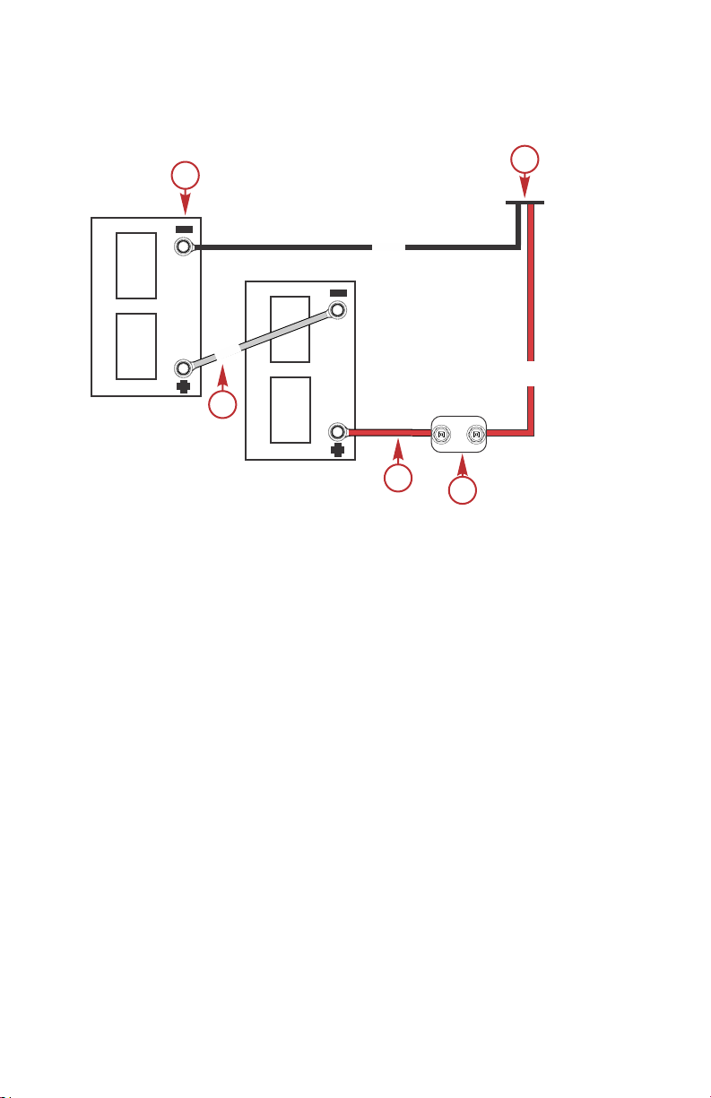
RED
BLACK
a
b
c
d
37824
GRAY
c
Battery A
Battery B
PRODUCT INSTALLATION, WIRING, AND BATTERY
INFORMATION
5. Starting with the positive (+) lead, reconnect the battery cables to the
engine starting or accessory battery.
24-volt battery connection
a - Power cables to trolling motor
b - Manual reset circuit breaker
c - Jumper wire (not supplied)
d - Negative (–) battery terminal
Wire and Cable Routing
• Route the trolling motor wires on the opposite side of the boat from other
boat wiring.
• The trolling motor should be connected to its own dedicated battery.
• Sensitive electronics, such as depth finders, must be connected to a
separate battery.
• Marine engines should have their own dedicated starting battery.
Activating the Handheld Remote
1. If the trolling motor power cables are connected, disconnect the power
cables from the trolling motor battery, starting with the negative (–) lead.
2. Deploy the motor, then connect the power cables to the battery or plug in
the power cable to a battery source. Within ten seconds of connecting the
power cables, press and hold the left and right arrow buttons on the
handheld remote simultaneously.
eng 15
Page 22
51842
b
a
c
d
e
PRODUCT INSTALLATION, WIRING, AND BATTERY
INFORMATION
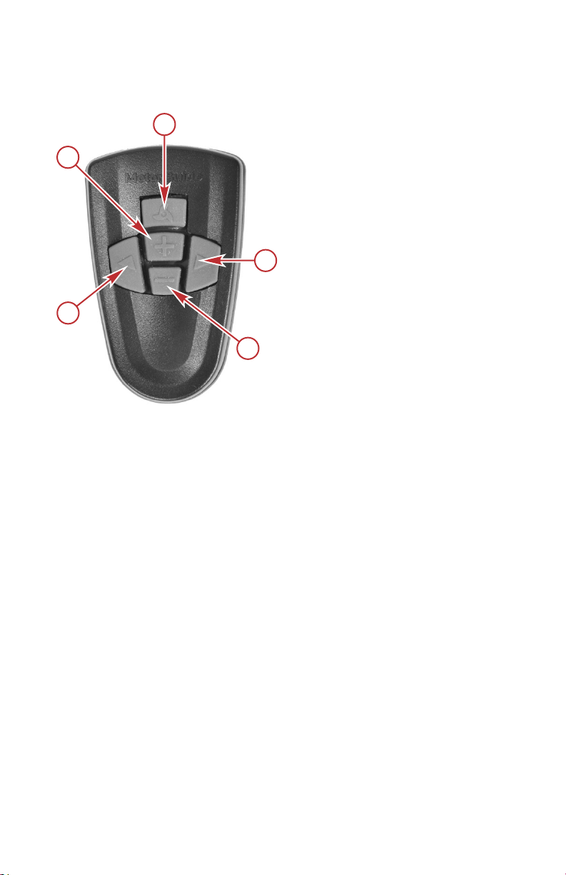
3. Listen for a multitone beep, which indicates that the receiver has stored
the electronic serial number.
a -
+ button—increase
speed
b -
Propeller button—
propeller on/off
c -
Right arrow button—
steer right
d -
– button—decrease
speed
e -
Left arrow button—
steer left
If you are having trouble syncing your remote, start with the motor unplugged
and deployed. Hold down the left arrow and right arrow buttons at the same
time before you plug in the motor.
Connecting the Sonar Display to the Trolling Motor
NOTE: This procedure applies only to models equipped with integrated sonar.
This sonar display connection procedure applies to trolling motor models with
internal sonar that offer built‑in 200/83 kHz sonar transducers compatible with
Eagle®, Garmin™, Humminbird™, Lowrance™, and Vexilar® brand sonar
displays. For compatibility with other sonar units, refer to www.motorguide.com.
16 eng
Page 23
a
b
64685
PRODUCT INSTALLATION, WIRING, AND BATTERY
INFORMATION
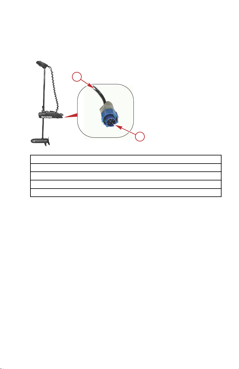
The trolling motor is equipped with a Lowrance 7‑pin plug. Adapters are
available to connect other brands of sonar displays to the trolling motor. Match
the cable connector to the sonar port on the back of the sonar display. Power
up the unit to ensure that the sonar cable is connected securely.
a - Harness—to nose cone
sonar
b - Lowrance 7‑pin plug—
to sonar display
Transducer Adapter Cables Available from MotorGuide
Lowrance 7‑to‑6‑pin adapter
Vexilar 3‑pin adapter
Garmin 6‑pin adapter
Humminbird 7‑pin adapter
Reducing Sonar Transducer Interference
The following items should be checked, in order, to help improve sonar
performance. Keep in mind, all sonar testing should be done on the water in
stable conditions.
1. Ensure you have separate grounds/no common ground between trolling
motor battery bank (12V, 24V, 36V) and engine/accessory battery bank
(12V).
2. Keep trolling motor power cables and sonar/electronics cables as far
apart as possible on the boat. (Example: Trolling motor cables routed on
the port side and electronics cables routed on the starboard side).
3. A multi‑bank charger that is connected to both the trolling motor bank and
engine/accessory battery bank can cause interference through the
common ground in the charger.
4. Ensure that none of your sonar cables are cut or damaged. Even
internally broken shielding can cause issues and can be identified by
carefully inspecting the rubberized outer coating for crimps, bends, and
flattened areas. Repair/replace as necessary.
5. Check for common external sources of interference and temporarily
remove or disable these to test for improvements in sonar performance.
These include:
eng 17
Page 24

PRODUCT INSTALLATION, WIRING, AND BATTERY
INFORMATION
a. Ethernet links
b. Multiple sonar transducers operating on same frequencies
c. Other 3rd party electronic equipment
6. Ferrite rings/chokes may have some positive effect on sonar
performance. Ensure you have the correct size for the gauge wire you are
installing on.
7. If sonar performance has still not improved, check with MFD/Electronics
manufacturers or your boat dealer to check for other boat wiring issues.
18 eng
Page 25
a
b
c
d
64899
TROLLING MOTOR OPERATION
Status Indicator Light Identification
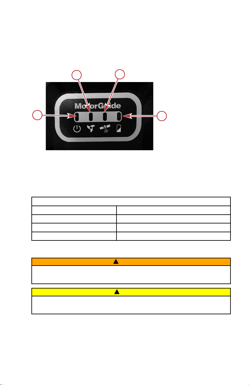
This trolling motor is equipped with a multifunction status indicator light panel. It
can display the on/off status of the motor, propeller, battery charge, and GPS
status for quick and easy reference during operation.
a - Power on/off/sleep indicator light
b - Propeller on/off indicator light
c - GPS navigation indicator light
d - Battery status light
Battery Status Light Color Code
Color Capacity
Green greater than 30%
Red less than 30%
Flashing red less than 10%
Stowing and Deploying the Trolling Motor
WARNING
!
Rotating propellers can cause serious injury or death. Never start or operate
the motor out of water.
!
CAUTION
Moving parts, such as hinges and pivot points, can cause serious injury.
Keep away from moving parts when stowing, deploying, or tilting the motor.
STOWING THE TROLLING MOTOR
1. Ensure the propeller is not running.
2. Ensure there is sufficient clearance around the trolling motor before
rotating the motor into stowed position.
eng 19
Page 26

a
64686
TROLLING MOTOR OPERATION
3. Press down on the foot release lever with one hand or foot. While
pressing down on the foot release lever, pull and tilt the trolling motor
towards the mount.
a - Foot release lever
20 eng
Page 27

a
b
c
d
e
f
64903
a
b
c
64688
TROLLING MOTOR OPERATION
4. Raise the motor out of the water and rotate the transmission so the lower
unit is aligned with the mount cradle. Orient the lower unit so the cable
does not wrap around the trolling motor column. Slide the lower unit into
the mount cradle until the lower unit is fully seated. The mount will lock
the trolling motor in the stowed position. If GPS equipped, it is common to
lose the GPS signal while stowed.
a - Lower unit (motor)
b - Transmission
c - Depth collar
d - Curly cable
e - Foot release lever
f - Mount cradle
5. Slide the depth collar so it is tight against the steering transmission.
Rotate the depth collar until it engages the steering transmission, then
tighten the depth collar knob.
a - Steering transmission
b - Depth collar
c - Depth collar knob
IMPORTANT: Trolling motor can unintentionally deploy if not fully secured.
Ensure the depth collar is fully seated with transmission and the depth collar
knob is tight any time the boat is underway or trailered.
eng 21
Page 28

a
b
c
d
e
f
64689
TROLLING MOTOR OPERATION
IMPORTANT: Optional column mount stabilizers are available for supporting
the trolling motor column in extremely rough boating conditions.
Recommended MotorGuide Accessory Description
Standard Ram® mount stabilizer
Long Ram® mount stabilizer
DEPLOYING THE TROLLING MOTOR
1. Loosen the depth collar knob, then slide the depth collar away from the
steering transmission. Tighten the depth collar knob by turning the knob
clockwise.
2. Press down on the foot release lever with one hand or one foot. Firmly
grasp the column and slide the lower unit away from the mount cradle.
Release the foot lever.
a - Lower unit (motor)
b - Depth collar
c - Column
d - Curly cable
e - Foot release lever
f - Mount cradle
3. Ensure there is sufficient clearance around the area where the trolling
motor will be deployed.
22 eng
Page 29

64904
a
b
TROLLING MOTOR OPERATION
4. Tilt the motor out of the stowed position and lower the trolling motor until
the depth collar rests on top of the steering housing collar. Rotate the
trolling motor so the depth collar locks into position on the steering
housing collar. The motor will lock into the deployed position. Pull back on
the column to ensure that it is securely locked into the deployed position.
a - Depth collar knob
b - Steering housing collar
Adjusting the Motor Depth
!
CAUTION
Avoid injury due to the sudden shifting of weight when deploying the motor or
adjusting the motor depth. When raising or lowering the motor, firmly grasp
the motor column with one hand before loosening the depth collar knob.
Adjust the depth of the motor to improve the trolling motor performance in
various water depths.
eng 23
Page 30

a
b
64905
TROLLING MOTOR OPERATION
IMPORTANT: Do not use the curly cable as a handle when raising or lowering
the motor.
When adjusting the motor depth, ensure that the lower unit is fully submerged a
minimum of 30 cm (12 in.) to avoid propeller ventilation. Optimal depth of the
lower unit will vary depending on the boat type, water conditions, and the
underwater terrain. If you hear the propeller blades splashing against the water
surface, lower the motor depth.
1. Ensure the propeller is not running before adjusting the depth of the
motor.
2. Firmly grasp the column with one hand and turn the depth collar knob
counterclockwise so the column moves freely.
a - Depth collar knob
b - Depth collar
3. Raise or lower the column to the desired depth. Align the depth collar to
the key slot on top of the transmission. Tighten the depth collar knob to
secure the column.
24 eng
Page 31

51842
b
a
c
d
e
TROLLING MOTOR OPERATION
Handheld Remote Operation
WARNING
!
Rotating propellers can cause serious injury or death. Never start or operate
the motor out of water.
To operate the trolling motor using the handheld remote, sync the foot pedal to
the trolling motor receiver. Refer to Activating the Handheld Remote in the
Product Installation, Wiring, and Battery Information section of this manual.
a - Increase speed
b - Propeller on/off
c - Right turn
d - Decrease speed
e - Left turn
TURNING THE HANDHELD REMOTE ON OR OFF
The handheld remote is always on, and is ready for use anytime that the trolling
motor is powered up and in the deployed position.
SLEEP MODE
• When the trolling motor is not in an active state and idle for more than
• The Sleep Mode state is indicated by the power LED slowly fading on and
three minutes, it will automatically enter Sleep mode, a low power state,
such as:
a. The propeller is not running.
b. The propeller is at zero speed.
c. No GPS mode is active.
off.
eng 25
Page 32

TROLLING MOTOR OPERATION
• The Sleep Mode state can start when the trolling motor is in the stowed or
deployed position.
• Wake the trolling motor from Sleep Mode by pressing any button on the
FOB or wireless foot pedal (sold separately).
• The next button pressed will activate the trolling motor and perform the
intended button function. Once the motor is activated all the functions will
operate normally.
STEERING
•
To turn left, press the left turn button on the handheld remote.
•
To turn right, press the right turn button on the handheld remote.
• The available steering range allows the trolling motor to turn beyond 360°
for operation in reverse. Take care not to stress the cables when rotating
the trolling motor beyond 360°.
SPEED CONTROL
•
Press the propeller on/off button once to start the propeller, and press
the propeller on/off button again to stop the propeller.
• The trolling motor will emit a single ascending‑tone beep when the
propeller is turned on and a single descending‑tone beep when the
propeller is turned off.
• The system is equipped with 20 speed levels. Press and release the
increase speed (+) button to increase motor speed by one level. Press
and release the decrease speed (–) button to reduce motor speed by one
level.
•
Holding the increase speed (+) or decrease speed (–) will cause the
speed level to increase or decrease until the speed level limit is reached.
Holding the increase speed (+) or decrease speed (–) button for 2.5
seconds will ramp up the speed level from 0% to 100%, or decrease from
100% to 0%, respectively. The trolling motor will emit two beeps when it
reaches the 100% or 0% speed level.
26 eng
Page 33

MAINTENANCE AND STORAGE
Trolling Motor Care
To keep your trolling motor in the best operating condition and retain its
dependability, your trolling motor must receive periodic inspections and
maintenance. Keep it maintained properly to ensure the safety of you and your
passengers.
WARNING
!
Neglecting to inspect, maintain, or repair your trolling motor can result in
product damage or serious injury or death. Do not perform maintenance or
service on your trolling motor if you are not familiar with the correct service
and safety procedures.
Record all maintenance performed and save maintenance work orders and
receipts.
SELECTING REPLACEMENT PARTS
Use only original MotorGuide replacement parts.
Inspection and Maintenance Schedule
BEFORE EACH USE
• Inspect for loose or corroded wiring connections.
• Check the tightness of the battery cable connections. Nylock nuts are
recommended for securing the battery cables to their terminals.
• Check the tightness of the propeller nut.
• Check the propeller blades for damage.
• Check the tightness of the mount to the deck of the boat.
AFTER EACH USE
• Disconnect the battery cables from the power source, or unplug the motor
from the boat or open the installed breaker.
• Check each side of the propeller and propeller shaft for debris such as
weeds and fishing line. Remove all debris.
• Check the tightness of the propeller nut.
• Wash the trolling motor with clean water and a mild soap such as
Attwood® Premium Boat Wash to remove dirt and dust that may scratch
the surface.
IMPORTANT: Do not use harsh cleaners such as bleach or citrus cleaners to
clean the trolling motor. These cleaners can damage the finish on the trolling
motor.
IMPORTANT: Do not power wash the trolling motor.
EVERY 100 HOURS OF USE OR ANNUALLY (WHICHEVER OCCURS
FIRST)
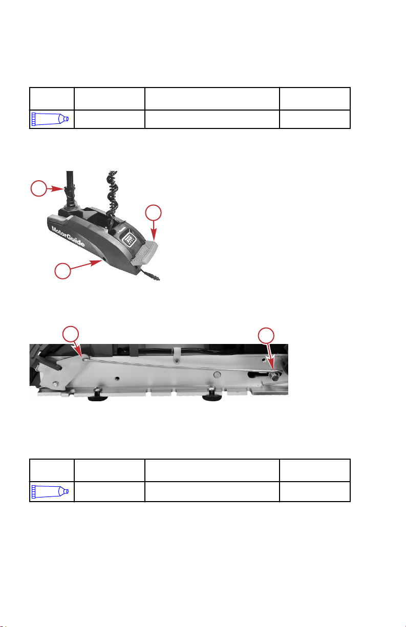
1. Apply 2‑4‑C with PTFE to the depth collar knob screw threads.
eng 27
Page 34
a
b
c
64691
a
b
64907
MAINTENANCE AND STORAGE
NOTE: 2‑4‑C with PTFE is a marine grease available at marine supply stores
and your MotorGuide dealer.
Tube Ref
No.
95
Description Where Used Part No.
2-4-C with PTFE Depth collar knob screw threads 92-802859A 1
2. Remove the side panels by removing the screw on each side of the
mount. Gently pull the cover away from the mount and towards the foot
release lever.
a - Depth collar knob screw threads
b - Foot release lever
c - Screw securing the side panel
3. Apply 2‑4‑C with PTFE to the release wire at the foot pedal pivot pin and
the release wire on the release pin.
a - Foot pedal pivot pin
b - Release pin
Tube Ref
No.
95
Description Where Used Part No.
2-4-C with PTFE
Release wire at the foot pedal pivot pin
and the release wire on the release pin
92-802859A 1
28 eng
Page 35

MAINTENANCE AND STORAGE
Storage Preparation
The major consideration in preparing your trolling motor for storage is to protect
it from corrosion and damage caused by freezing of trapped water. It is also
recommended that batteries are disconnected prior to storage and that the
batteries are stored indoors in a dry location during long‑term storage. The
batteries should also be removed from the handheld remote and wireless foot
pedal for long‑term storage.
Refer to the Inspection and Maintenance Schedule and complete the
appropriate care instructions to prepare your trolling motor for storage. Store
the trolling motor in a dry location where it will not be affected by temperatures
below –29 °C (–20 °F).
IMPORTANT: Trolling motors stored in temperatures below 0 °C (32 °F) should
be operated slowly for a minimum of 15 minutes before going above 30%
throttle.
Battery Inspection
The battery should be inspected at periodic intervals to ensure proper trolling
motor operation.
IMPORTANT: Read the safety and maintenance instructions that accompany
your battery.
1. Ensure that the battery is secured to the vessel.
2. Ensure that the battery cable terminals are clean, tight, and correctly
installed. For installation instructions, refer to Battery Connection in the
Product Installation, Wiring, and Battery Information section of this
manual.
3. Ensure that the battery is equipped with a battery box to prevent
accidental shorting of the battery terminals.
Corrosion Control Anode (Saltwater Models)
The anode helps protect the trolling motor against galvanic corrosion by
sacrificing its metal to be slowly eroded instead of the trolling motor metal
components. The anode requires periodic inspection, especially in saltwater
which will accelerate the erosion. To maintain this corrosion protection, replace
the anode if it is more than 50% eroded. Never paint or apply a protective
coating to the anode as this will reduce effectiveness of the anode.
eng 29
Page 36
a
b
c
d
62099
MAINTENANCE AND STORAGE
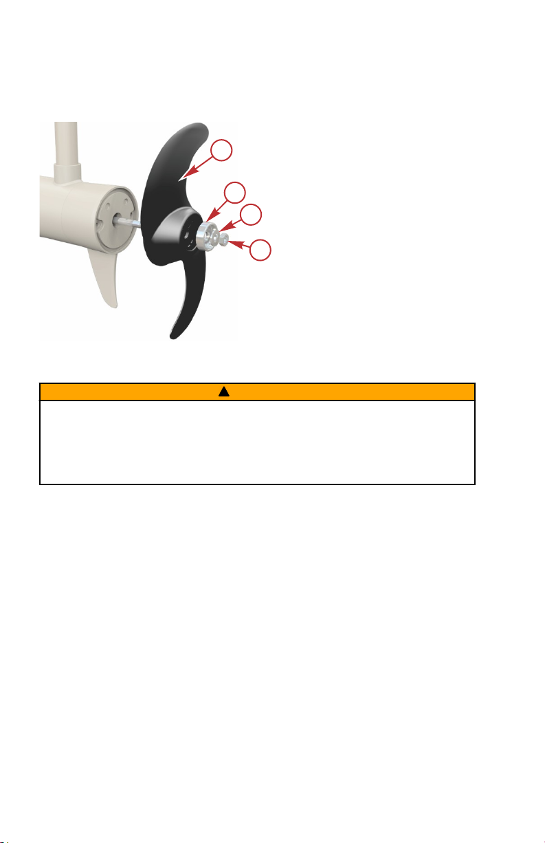
IMPORTANT: Do not paint the anode or clean it with steel wool, sandpaper,
wire brushes, or other abrasive materials. Replace the anode if it is more than
50% eroded.
a - Propeller
b - Anode (saltwater models
only)
c - Washer
d - Propeller nut
Propeller Replacement
WARNING
!
Performing service or maintenance without first disconnecting the battery can
cause product damage, personal injury, or death due to fire, explosion,
electrical shock, or unexpected motor starting. Always disconnect the battery
cables from the battery before maintaining, servicing, installing, or removing
motor components.
REMOVING THE PROPELLER
1. Disconnect the power cables from the battery.
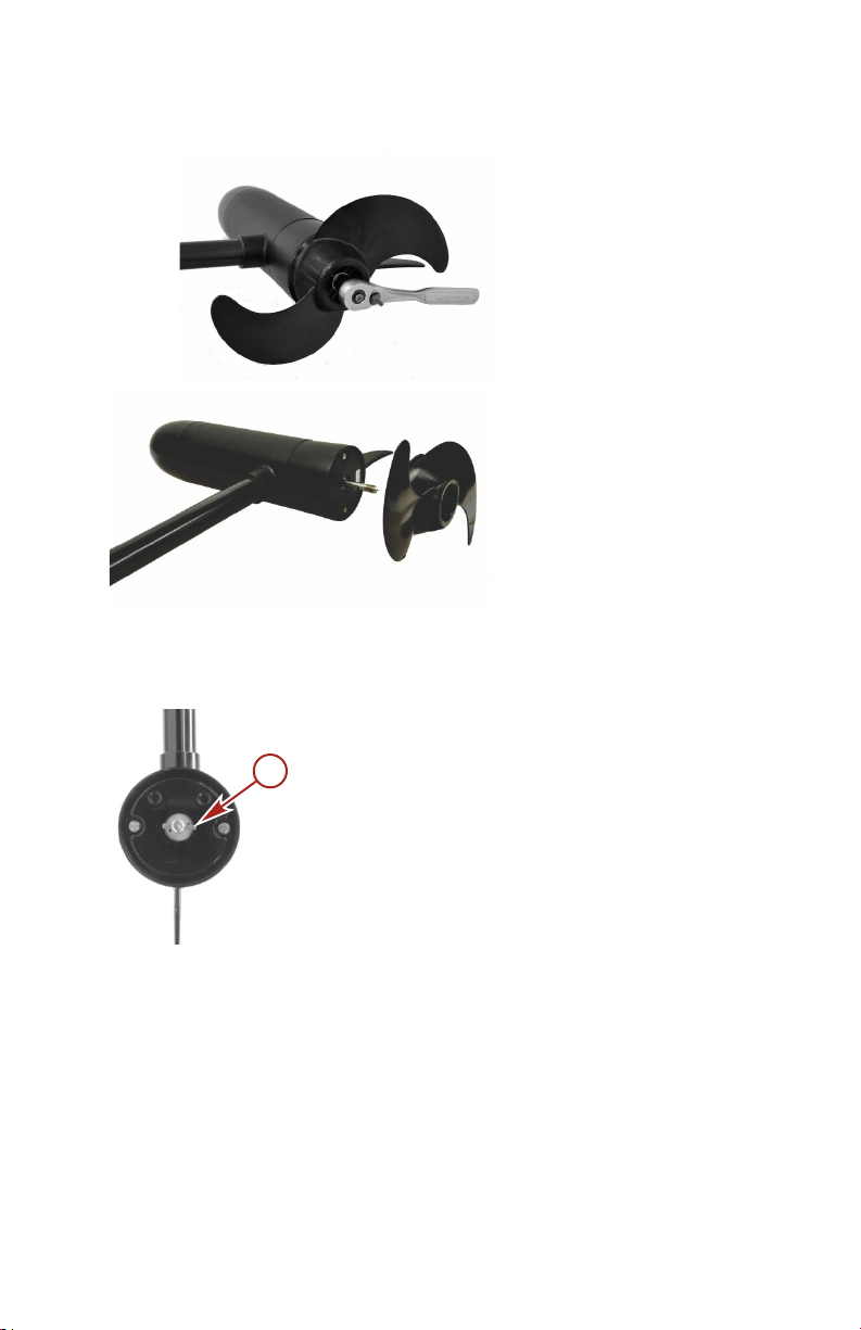
2. While holding the propeller blade with one gloved hand, use a 9/16 in.
wrench or a ratchet to remove the propeller nut. Remove the propeller nut
and washer (or anode, for saltwater models).
IMPORTANT: Remove the propeller nut with a wrench or a ratchet and socket.
Using another tool may damage the propeller nut or shaft. If the propeller
cannot be removed easily, use a rubber mallet to lightly tap the back side of
the opposite blade. If the propeller cannot be removed, have the propeller
removed by an authorized dealer.
30 eng
Page 37
53442
57326
a
44664
MAINTENANCE AND STORAGE
NOTE: Replace the propeller pin if it is bent.
INSTALLING THE PROPELLER
1. Rotate the motor shaft to insert the propeller pin horizontally.
a - Propeller pin
2. Install the propeller onto the motor shaft by engaging the propeller onto
the propeller pin.
3. Install the washer (and anode, for saltwater models) onto the propeller
shaft, then install the propeller nut. Use a wrench or a socket and ratchet
to tighten the propeller nut until it is snug, then tighten the nut another 1/4
turn.
eng 31
Page 38
a
b
c
d
62099
MAINTENANCE AND STORAGE
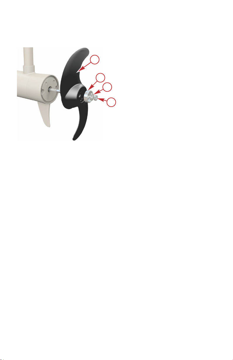
IMPORTANT: Do not overtighten the propeller nut, or damage to the propeller
or propeller pin may occur.
Saltwater model shown
a - Propeller
b - Anode (saltwater models
only)
c - Washer
d - Propeller nut
32 eng
Page 39

OWNER SERVICE ASSISTANCE
Troubleshooting
NOTE: For service information, contact any certified MotorGuide service
center. For a full listing of MotorGuide service centers, go to
www.motorguide.com or contact any Mercury Marine service office.
Symptom Possible Cause Resolution
Check the battery charge indicator
on the trolling motor. Recharge or
replace batteries as required.
Replace the handheld remote
battery or foot pedal batteries.
Refer to Activating the Wireless
Foot Pedal or Activating the
Handheld Remote.
Check the battery charge indicator
on the trolling motor. Recharge or
replace the batteries as required.
Inspect battery connections for
cleanliness and tightness.
Refer to Propeller Replacement.
Wire gauge from the battery to the
trolling motor is insufficient.
6‑gauge wire is recommended.
The motor will whine or grind.
Contact a Service Center.
Contact a Service Center.
Trolling motor does
not respond to
wireless commands
Loss of power
Weak trolling motor
batteries
Weak handheld
remote battery or
weak foot pedal
battery
Wireless
controllers not
synced
Weak trolling motor
batteries
Loose or corroded
battery
connections
Propeller is loose,
damaged, or
off‑balance
Wiring or electrical
connection faulty
Magnets cracked
or chipped
Water intrusion in
the lower unit
eng 33
Page 40

OWNER SERVICE ASSISTANCE
Symptom Possible Cause Resolution
Propeller is loose,
Excessive noise or
vibration
Motor failure
(motor runs at
partial speed)
Trolling motor
flashes the propeller
LED and battery
LED while emitting a
siren noise
damaged, or
off‑balance
Damaged bearings
or bushings
Magnets interfering
with armature
Magnets cracked
or chipped
Loose electrical
connections
Motor has reached
thermal limit
Propeller is loose,
damaged, or
off‑balance
Internal electronics
fault
Refer to Propeller Replacement.
Contact a Service Center.
Turn off the power and manually
rotate the propeller. If the propeller
does not rotate freely with a slight
magnetic drag, contact a Service
Center.
The motor will whine or grind.
Contact a Service Center.
Connections in the head may be
loose or damaged. Contact a
Service Center.
Temperature exceeds
specification. Contact a Service
Center.
Refer to Propeller Replacement.
Disconnect battery power. Contact
a Service Center.
34 eng
Page 41

OWNER SERVICE ASSISTANCE
Symptom Possible Cause Resolution
Check the battery charge indicator
on the trolling motor. Recharge or
replace the battery as required.
Refer to Troubleshooting the
Foot Pedal and Handheld
Remote.
Inspect battery connections for
cleanliness and tightness.
Wire gauge from the battery to the
trolling motor is insufficient.
6‑gauge wire is recommended.
Inspect connections for
cleanliness and tightness.
Disconnect the trolling motor
batteries and check for weeds or
debris around the propeller.
Temperature exceeds
specification. Contact a Service
Center.
Replace the fuse or reset the
circuit breaker only after
determining the root cause of the
problem.
Turn off the power and manually
rotate the propeller. If the propeller
does not rotate freely with a slight
magnetic drag, contact a Service
Center.
Adjust the depth of the motor.
Ensure the lower unit is fully
submerged. Refer to Adjusting
the Motor Depth.
Contact a Service Center.
Contact a Service Center.
Motor failure
(motor does not run)
Inaccurate
temperature reading
(models with internal
sonar)
Weak trolling motor
batteries
Batteries in the foot
pedal or handheld
remote need
replacement
Loose or corroded
battery
connections
Wiring or electrical
connection faulty
Loose electrical
connections
Thermal protection
is overloaded
Fuse or circuit
breaker is open
Magnets interfering
with armature
Boat wiring faulty Contact a Service Center.
Lower unit not fully
submerged
Damaged nose
cone
Damaged sonar
cable
eng 35
Page 42

OWNER SERVICE ASSISTANCE
Symptom Possible Cause Resolution
Hold one blade and lightly tap the
opposite blade with a rubber
Difficulty removing
propeller
Bent propeller pin
Bent armature
shaft
Troubleshooting the Handheld Remote
ERASING THE RECEIVER'S MEMORY
Erasing the receiver's memory will erase all electronic ID numbers that are
stored in the receiver's memory.
1. Plug in the battery cable to a power source. In less than ten seconds,
press the left, propeller, and right buttons on the handheld remote
simultaneously.
2. Listen for a long beep indicating the receiver has erased all stored
electronic ID numbers.
NOTE: If the buttons on the remote are not pressed simultaneously within ten
seconds, or a long beep is not heard, unplug the battery cables from the
power source and then refer to
Activating the Handheld Remote
Battery Information
section of this manual.
REPROGRAMMING THE REMOTE
NOTE: This activation procedure applies to the foot pedal and handheld
remote.
IMPORTANT: To activate multiple foot pedals or remotes, the motor must be
unplugged from the power source and then plugged back into the power source
between activating each control device.
1. Deploy the trolling motor.
2. Unplug the battery cables from the power source. Wait 30 seconds and
then reconnect the motor to the power source.
3.
In less than ten seconds, press and hold the left arrow and right arrow
buttons simultaneously on the handheld remote. For the foot pedal
controller, hold the propeller and anchor button simultaneously.
HANDHELD REMOTE BATTERY REPLACEMENT
Battery required: One AAA alkaline battery
Activating the Wireless Foot Pedal
in the
mallet.
Use a putty knife on both sides of
the propeller to apply equal
pressure.
Contact a Service Center.
and
Product Installation, Wiring, and
36 eng
Page 43
51838
a
a
a a
51837
OWNER SERVICE ASSISTANCE
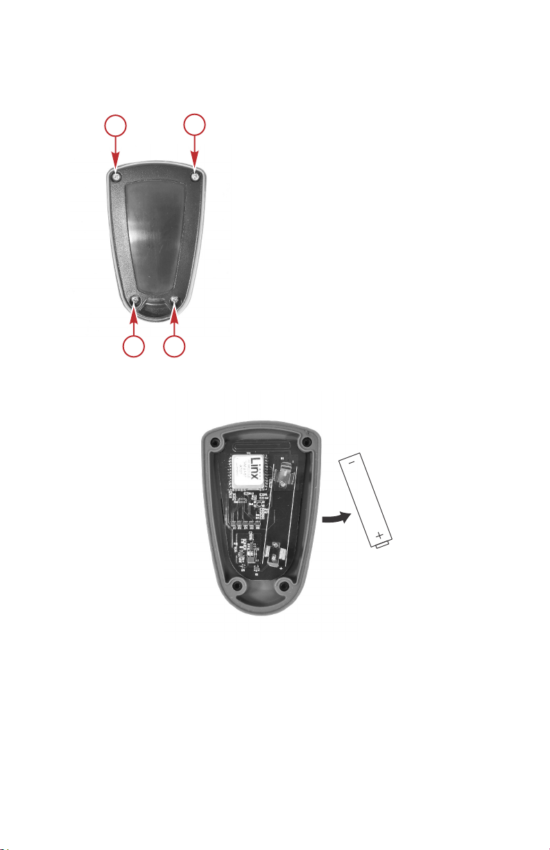
1. Remove the four screws from the back of the handheld remote. Remove
the back cover.
a - Screws (4)
2. Remove the old battery from the battery holder.
3. Insert the new battery with the positive (+) side facing the positive (+) end
eng 37
of the battery holder.
Page 44
a
b
c
d
51839
OWNER SERVICE ASSISTANCE
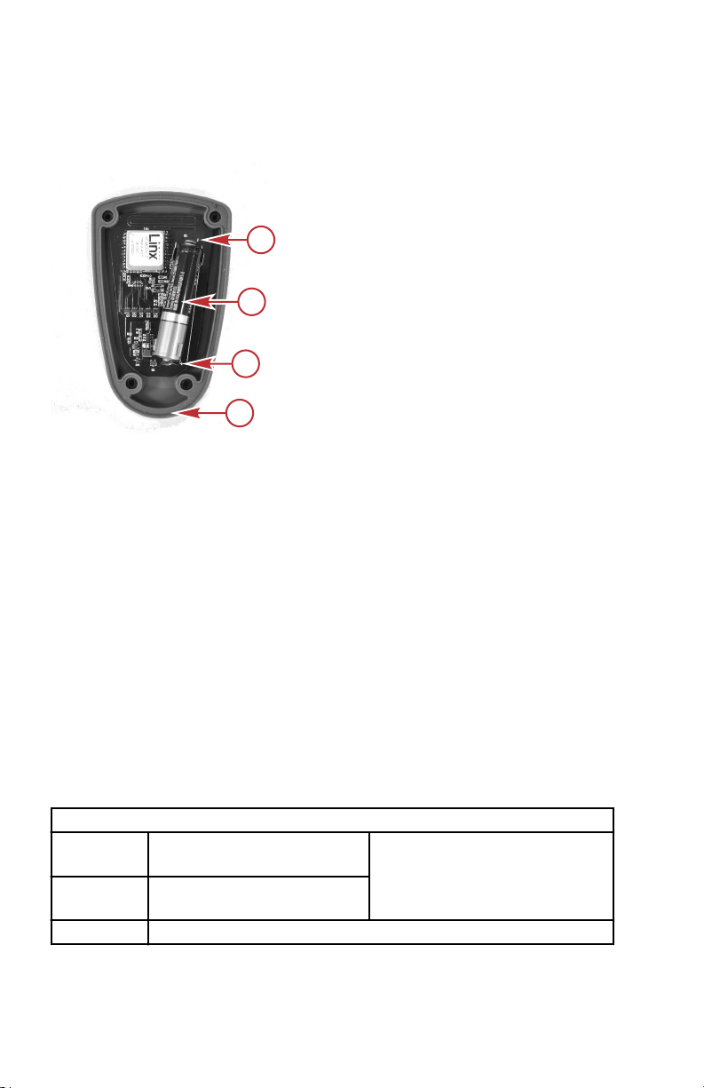
4. Ensure that the rubber seal is positioned correctly between the two halves
of the handheld remote. Replace the handheld remote back cover and
install the four screws. Carefully tighten the screws.
a - Negative (–) end of battery holder
b - Battery
c - Positive (+) end of battery holder
d - Rubber seal
Service Assistance
Your satisfaction with your product is very important to us. If you have a
problem or question about your motor, contact your dealer or any certified
MotorGuide Service Center. For more service assistance information, refer to
Warranty Information.
The following information will be needed by the service office:
• Your name and address
• Daytime telephone number
• Model and serial number of your trolling motor
• Proof of purchase or registration verification
• Nature of problem
Mercury Marine Service Offices
For assistance, call, fax, or write. Please include your daytime telephone
number with mail and fax correspondence.
United States, Canada
Telephone
Fax
Website www.mercurymarine.com
English +1 920 929 5040
Français + 905 636 4751
English +1 920 929 5893
Français +1 905 636 1704
Mercury Marine
W6250 Pioneer Road
P.O. Box 1939
Fond du Lac, WI 54936-1939
38 eng
Page 45

OWNER SERVICE ASSISTANCE
Australia, Pacific
Telephone +61 3 9791 5822 Brunswick Asia Pacific Group
41–71 Bessemer Drive
Fax +61 3 9706 7228
Europe, Middle East, Africa
Telephone +32 87 32 32 11 Brunswick Marine Europe
Fax +32 87 31 19 65
Mexico, Central America, South America, Caribbean
Telephone +1 954 744 3500 Mercury Marine
Fax +1 954 744 3535
Asia, Singapore, Japan
Telephone +65 65466160 Brunswick Asia Pacific Group
Fax +65 65467789
Dandenong South, Victoria 3175
Australia
Parc Industriel de Petit-Rechain
B-4800 Verviers,
Belgium
11650 Interchange Circle North
Miramar, FL 33025
U.S.A.
T/A Mercury Marine Singapore Pte Ltd
29 Loyang Drive
Singapore, 508944
eng 39
 Loading...