

Page 1

Operation
Maintenance
Installation
Warranty
8M4003879 120 eng
Manual
Tour Pro 82/Tour Pro 109
© 2020 Mercury Marine
Page 2

eng
Page 3

Compliance Statement
This device complies with Part 15 of the FCC Rules. Operation is subject to the
following two conditions: (1) this device may not cause harmful interference,
and (2) this device must accept any interference received, including
interference that may cause undesired operation. This device complies with
FCC Rules. Changes or modifications not expressly approved by MotorGuide
could void the user's authority to operate the equipment. This device complies
with Industry Canada license‑exempt RSS standard(s). Operation is subject to
the following two conditions: (1) this device may not cause interference, and (2)
this device must accept any interference, including interference that may cause
undesired operation of the device. Le présent appareil est conforme aux CNR
d'Industrie Canada applicables aux appareils radio exempts de licence.
L'exploitation est autorisée aux deux conditions suivantes : (1) l'appareil ne doit
pas produire de brouillage, et (2) l'utilisateur de l'appareil doit accepter tout
brouillage radioélectrique subi, même si le brouillage est susceptible d'en
compromettre le fonctionnement.
Environmental Compliance Statement
All MotorGuide products that are subject to the Directive 2012/19/EU WEEE
directive are compliant with the WEEE marking requirement. Such products are
marked with the "crossed‑out wheelie bin" WEEE symbol (shown, below) in
accordance with European Standard EN50419.
The symbol on the product or its packaging indicates that this product must not
be disposed of with your other household waste. Instead, it is your
responsibility to dispose of your waste equipment by handing it over to a
designated collection point for the recycling of waste electrical and electronic
equipment. The separate collection and recycling of your waste equipment at
the time of disposal will help conserve natural resources and ensure that it is
recycled in a manner that protects human health and the environment. For
more information about where you can drop off your waste for recycling, please
contact your local authority, or where you purchased your product.
CE Declaration
An official copy of the Declaration of Conformity can be found at https://
www.motorguide.com/us/en/support‑certifications.html.
Thank You
Thank you for choosing MotorGuide, one of the finest trolling motors available.
Years of experience have been committed to the goal of producing the finest
quality products. This led to MotorGuide's reputation for strict quality control,
excellence, durability, long‑lasting performance and being the best at providing
after‑the‑sale service and support.
eng i
Page 4

Please read this manual carefully before operating your motor. This manual
has been prepared to assist you in the operation, safe use, and care of your
trolling motor.
Again, thank you for your confidence in MotorGuide.
Warranty Message
The product you have purchased comes with a Three Year Limited Warranty
from MotorGuide, the terms of the policy are set forth in the Warranty
Information section of this manual. The policy statement contains a description
of the duration of coverage, important disclaimers and limitations of
damages, and other related information. Please review this important
information.
The description and specifications contained herein were in effect at the time
this manual was approved for printing. MotorGuide, whose policy is one of
continued improvement, reserves the right to discontinue models at any time, to
change specifications, designs, methods, or procedures without notice and
without incurring obligation.
MotorGuide, Lowell, Michigan U.S.A.
Copyright and Trademark Information
© MERCURY MARINE. All rights reserved. Reproduction in whole or in
part without permission is prohibited.
Alpha, Axius, Bravo One, Bravo Two, Bravo Three, Circle M with Waves Logo,
K‑planes, Mariner, MerCathode, MerCruiser, Mercury, Mercury with Waves
Logo, Mercury Marine, Mercury Precision Parts, Mercury Propellers, Mercury
Racing, MotorGuide, OptiMax, Quicksilver, SeaCore, Skyhook, SmartCraft,
Sport‑Jet, Verado, VesselView, Zero Effort, Zeus, #1 On the Water and We're
Driven to win are registered trademarks of Brunswick Corporation. Pro XS is a
trademark of Brunswick Corporation. Mercury Product Protection is a registered
service mark of Brunswick Corporation.
ii eng
Page 5

Warranty Information
Disclaimers, Limitations, and Waivers................................................................ 1
MotorGuide Limited Three Year Warranty.......................................................... 2
General Information
Boater's Responsibilities..................................................................................... 4
Protecting People in the Water........................................................................... 4
Passenger Safety Message................................................................................ 4
Safe Boating Suggestions.................................................................................. 4
Product Overview
Box Contents...................................................................................................... 6
Tour Pro 82/Tour Pro 109 MotorGuide Trolling Motor........................................ 9
Specifications....................................................................................................10
Wiring and Battery Information
Wiring and Battery Information......................................................................... 11
Recommended Practice and Procedures......................................................... 11
Battery Recommendations............................................................................... 11
Battery Precautions.......................................................................................... 12
Wire and Cable Routing....................................................................................12
Wire Color Code Abbreviations........................................................................ 13
Battery Connection........................................................................................... 13
eng iii
Page 6

Trolling Motor Installation and Operation
Installing the Steering System on the Mount.................................................... 16
Trolling Motor Installation..................................................................................18
Permanent Foot Pedal Mounting—Optional..................................................... 21
Bounce Buster Installation................................................................................ 22
Installing the Gas Spring...................................................................................24
NMEA 2000 Pinpoint Connection..................................................................... 25
Connecting the Sonar Display to the Trolling Motor......................................... 26
Reducing Sonar Transducer Interference.........................................................27
Cable Routing Clip Installation..........................................................................28
Stowing the Trolling Motor................................................................................ 29
Deploying the Trolling Motor............................................................................. 30
Adjusting the Trolling Motor Depth................................................................... 32
Directional Indicator.......................................................................................... 33
Pinpoint GPS Overview.................................................................................... 34
Operating the Pinpoint GPS System................................................................ 40
Speed Control................................................................................................... 61
Tour Pro Pedal Resistance Settings................................................................. 61
Maintenance
Trolling Motor Care........................................................................................... 63
Inspection and Maintenance Schedule............................................................. 63
Lubrication Points............................................................................................. 64
Battery Inspection............................................................................................. 64
Propeller Replacement..................................................................................... 65
Adjusting the Steering Cable Tension.............................................................. 66
Troubleshooting
Trolling Motor Performance.............................................................................. 67
Reducing Sonar Transducer Interference.........................................................68
Owner Service Assistance
Mercury Marine Service Offices........................................................................ 70
iv eng
Page 7

WARRANTY INFORMATION
Disclaimers, Limitations, and Waivers
No individual or entity, including Mercury Marine authorized dealers, has been
given authority by Mercury Marine to make any affirmation, representation or
warranty regarding the Product, other than those contained in this Mercury
Marine Limited Warranty, and if made, shall not be enforceable against
Mercury Marine.
DISCLAIMERS AND LIMITATIONS:
THE IMPLIED WARRANTIES OF MERCHANTABILITY AND FITNESS FOR
A PARTICULAR PURPOSE ARE EXPRESSLY DISCLAIMED. TO THE
EXTENT THAT THEY CANNOT BE DISCLAIMED, THE IMPLIED
WARRANTIES ARE LIMITED IN DURATION TO THE LIFE OF THE
EXPRESS WARRANTY. INCIDENTAL AND CONSEQUENTIAL DAMAGES
ARE EXCLUDED FROM COVERAGE UNDER THIS WARRANTY. SOME
STATES/COUNTRIES DO NOT ALLOW FOR THE DISCLAIMERS,
LIMITATIONS, AND EXCLUSIONS IDENTIFIED ABOVE; AS A RESULT,
THEY MAY NOT APPLY TO YOU. THIS WARRANTY GIVES YOU
SPECIFIC LEGAL RIGHTS, AND YOU MAY ALSO HAVE OTHER LEGAL
RIGHTS THAT VARY FROM STATE TO STATE AND COUNTRY TO
COUNTRY.
SUBMISSION TO JURISDICTION
ANY LEGAL SUIT, ACTION, OR PROCEEDING ARISING OUT OF OR
RELATING TO THIS MERCURY MARINE LIMITED WARRANTY OR THE
TRANSACTIONS CONTEMPLATED HEREBY SHALL BE INSTITUTED IN
THE COURT OF THE STATE OF WISCONSIN, COUNTY OF MILWAUKEE,
AND EACH PARTY IRREVOCABLY SUBMITS TO THE EXCLUSIVE
JURISDICTION OF SUCH COURT IN ANY SUCH SUIT, ACTION, OR
PROCEEDING. THE PARTIES IRREVOCABLY AND UNCONDITIONALLY
WAIVE ANY OBJECTION TO JURISDICTION AND/OR VENUE OF ANY
SUIT, ACTION, OR PROCEEDING IN SUCH COURTS AND IRREVOCABLY
WAIVE AND AGREE NOT TO PLEAD OR CLAIM IN ANY SUCH COURT
THAT ANY SUCH SUIT, ACTION, OR PROCEEDING BROUGHT IN ANY
SUCH COURT HAS BEEN BROUGHT IN AN INCONVENIENT FORUM.
ALL CLAIMS MUST BE BROUGHT IN THE PARTIES’ INDIVIDUAL
CAPACITY, AND NOT AS A CLASS MEMBER IN ANY PURPORTED
CLASS OR REPRESENTATIVE PROCEEDING.
GOVERNING LAW
ALL MATTERS ARISING OUT OF OR RELATING TO THIS MERCURY
MARINE LIMITED WARRANTY SHALL BE GOVERNED BY AND
CONSTRUED IN ACCORDANCE WITH THE INTERNAL LAWS OF THE
STATE OF WISCONSIN WITHOUT GIVING EFFECT TO ANY CHOICE OR
CONFLICT OF LAW PROVISION OR RULE (WHETHER OF THE STATE OF
WISCONSIN OR ANY OTHER JURISDICTION).
eng 1
Page 8

WARRANTY INFORMATION
MotorGuide Limited Three Year Warranty
KEEP YOUR ORIGINAL PURCHASE RECEIPT
1. To obtain warranty service, the purchaser should deliver or return the unit
(postage prepaid and insured) to any MotorGuide authorized service
center. DO NOT RETURN TO PLACE OF PURCHASE unless they are
an authorized service center. Motors purchased in other countries should
be returned to place of purchase. Products returned by mail should be
carefully packaged and include a note describing the nature of the
problem and/or service requested, customer address, and phone number.
A copy of the receipt, Bill of Sale, registration verification, or other proof of
purchase is required with the return of the product for warranty
consideration. Warranty claims will not be accepted without presentation
of purchase receipt for trolling motor, other verification of registration, or
Bill of Sale for boat package.
2. MotorGuide electric trolling motors are warranted to the original purchaser
to be free from defects in material and/or workmanship for three (3) years.
3. MotorGuide, at its discretion, will repair or replace items covered under
the terms of this warranty. Neither MotorGuide nor MotorGuide service
dealers are responsible for damages to MotorGuide products due to
repairs performed by anyone other than the MotorGuide Factory Service
Center. Neither MotorGuide nor Mercury Marine is responsible for failure
or damage caused by improper installation, set‑up, preparation, or
previous service or repair errors.
4. Warranty coverage is available only to customers that purchase from a
dealer authorized by MotorGuide/Mercury Marine to distribute the product
in the country in which the sale occurred. Warranty coverage and duration
varies by the country in which the product resides. This warranty applies
to Tour MotorGuide trolling motors sold and residing in the United States.
This Limited Warranty begins on the date the product is first sold to a
purchaser or the date on which the product is first put into service,
whichever occurs first. MotorGuide accessories are covered by this
Limited Warranty for a coverage period of one (1) year from the date of
retail sale. The repair or replacement of parts, or the performance of
service under this warranty, does not extend the life of this warranty
beyond its original expiration date. Promotional warranties are not
included in this statement and coverage may vary by promotion. Product
either sold or put into service more than six years from date of
manufacture is excluded from warranty coverage.
5. MotorGuide Composite Shaft Limited Lifetime Warranty. MotorGuide
composite shafts are warranted to the original retail purchaser to be free
of defects in material or workmanship for the lifetime of the original
purchaser. MotorGuide will provide a new composite shaft at no cost for
any composite shaft which contains a defect in material or workmanship.
The installation costs are the sole responsibility of the purchaser.
2 eng
Page 9

WARRANTY INFORMATION
6. This warranty does not apply to normal worn parts, i.e., worn cables,
adjustments, or product damage due to 1) neglect, lack of maintenance,
accident, abnormal operation or improper installation or service; 2) abuse,
i.e., bent metal columns, bent armature shafts, broken control cables, etc.,
accidents, modifications, misuse, excessive wear or damage caused by
an owner’s failure to provide reasonable and necessary installation or
care; 3) use of an accessory or part not manufactured by MotorGuide/
Mercury; 4) alteration or removal of parts; 5) opening the lower unit
(motor) by anyone other than the Factory Service Center will void this
warranty.
7. This warranty will not apply to haul‑out, launch, towing and storage,
transportation charges and/or travel time, telephone or rental charges of
any type, inconvenience, or loss of time or income, or other consequential
damages.
8. We reserve the right to improve the design of any trolling motor without
assuming any obligation to modify any trolling motor previously
manufactured.
9. Serialized "Service‑Repair" motors have a one (1) year warranty.
Nonserialized "Service‑Repair" electric trolling motors are NOT warranted.
"Service‑Repair" motor denotes a trolling motor sold by MotorGuide that
may be "used," but has been inspected and may have had minor repairs.
Original retail purchaser of a "Service‑Repair" motor is the first purchaser
of the motor after it is denoted as "Service‑Repair." "Service‑Repair"
motors have a blue sticker on the battery cable and box denoting
"Manufacturer Certified Service‑Repair Motor."
10. TERMINATION OF COVERAGE: Warranty coverage may be terminated
for repossessed product, or product purchased at auction, from a salvage
yard, from a liquidator, from an insurance company, from unauthorized
marine dealers or boatbuilders, or other third party entities.
11. ALL INCIDENTAL AND/OR CONSEQUENTIAL DAMAGES ARE
EXCLUDED FROM THIS WARRANTY, WARRANTIES OF
MERCHANTABILITY AND FITNESS ARE EXCLUDED FROM THIS
WARRANTY, IMPLIED WARRANTIES ARE LIMITED TO THE LIFE OF
THIS WARRANTY, SOME STATES DO NOT ALLOW LIMITATIONS ON
HOW LONG AN IMPLIED WARRANTY LASTS OR THE EXCLUSION
OR LIMITATION OF INCIDENTAL OR CONSEQUENTIAL DAMAGES,
SO THE ABOVE LIMITATIONS OR EXCLUSIONS MAY NOT APPLY TO
YOU. THIS WARRANTY GIVES YOU SPECIFIC LEGAL RIGHTS, AND
YOU MAY ALSO HAVE OTHER LEGAL RIGHTS WHICH MAY VARY
FROM STATE TO STATE.
eng 3
Page 10
21604
GENERAL INFORMATION
Boater's Responsibilities
The operator (driver) is responsible for the correct and safe operation of the
boat and safety of its occupants and general public. It is strongly recommended
that each operator (driver) read and understand this entire manual before
operating the trolling motor.
Be sure at least one additional person on board is instructed in the basic
operation of the trolling motor in case the driver is unable to operate the boat.
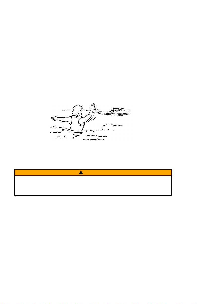
Protecting People in the Water
WHILE YOU ARE TROLLING
It is very difficult for a person in the water to take quick action to avoid a boat
heading in their direction, even at slow speeds.
Always slow down and exercise extreme caution any time you are boating in an
area where there might be people in the water.
WHILE THE BOAT IS STATIONARY
WARNING
!
A spinning propeller, a moving boat, or any solid device attached to the boat
can cause serious injury or death to swimmers. Stop the trolling motor
immediately whenever anyone in the water is near your boat.
Shut off the trolling motor before allowing people to swim or be in the water
near your boat.
Passenger Safety Message
Whenever the boat is in motion, observe the location of all passengers. A
sudden reduction in boat speed, such as a sharp change of boat direction,
could throw them off the boat.
Safe Boating Suggestions
In order to safely enjoy the waterways, familiarize yourself with local and other
governmental boating regulations and restrictions, and consider the following
suggestions.
Use flotation devices. It is the law to have an approved personal flotation
device of suitable size for each person aboard and have it readily accessible.
4 eng
Page 11

GENERAL INFORMATION
Do not overload your boat. Most boats are rated and certified for maximum
load (weight) capacities, refer to your boat capacity plate. If in doubt, contact
your dealer or the boat's manufacturer.
Perform safety checks and required maintenance. Follow a regular
schedule and ensure all repairs are made properly.
Never be under the influence of alcohol or drugs while boating (it is the
law). Alcohol or drug use impairs your judgment and greatly reduces your
ability to react quickly.
Passenger boarding. Stop the trolling motor whenever passengers are
boarding or unloading.
Be alert. The operator of the boat is responsible by law to maintain a proper
lookout by sight and hearing. The operator must have an unobstructed view
particularly to the front. No passengers, load, or fishing seats should block the
operators view when operating the boat.
Underwater hazards. Reduce speed and proceed with caution whenever
navigating in shallow water.
Tripping hazards. To avoid a trip hazard, route all cables and wiring neatly
and out of the way.
Report accidents. Boat operators are required by law to file a Boating
Accident Report with their state boating law enforcement agency when their
boat is involved in certain boating accidents. A boating accident must be
reported if 1) there is loss of life or probable loss of life, 2) there is personal
injury requiring medical treatment beyond first aid, 3) there is damage to boats
or other property where the damage value exceeds $500.00 or 4) there is
complete loss of the boat. Seek further assistance from local law enforcement.
eng 5
Page 12
a
b
c
d
e
f
g
i
j
k
l
m
n
o
q
r
s
h
p
t
u
v
w
70276
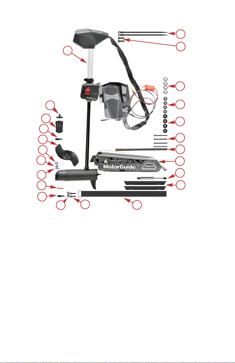
PRODUCT OVERVIEW
6 eng
Page 13

PRODUCT OVERVIEW
Ref. No. Qty. Description
a 1 Steering assembly
b 2 Cable routing cable tie
c 2 Cable routing cable tie screws
d 4 Nylon lock nuts
e 4 Mounting washers
f 4 Rubber mounting spacers
g 4 Mounting screws
h 1 Bounce buster assembly
i 1 Mount
j 1 Gas spring
k 2 Cable routing clips
l 1 Tie down strap
m 2 Allen screws
n 2 Plastic retaining washers
o 1 T20 Torx bit
p 1 Self‑tapping screw
q 1 Propeller pin
r 1 Propeller washer
s 1 Propeller nut
t 1 Katana propreller
u 1 T40 Torx bit
v 1 Pinpoint GPS remote
w 1 NMEA 2000 T‑connector
Box Contents
eng 7
Page 14

PRODUCT OVERVIEW
RECOMMENDED TOOL LIST
The following list of tools is recommended to aid in assembly and installation of
the motor.
1. Drill
2. 6 mm (1/4 in.) drill bit
3. P3 screwdriver
4. 11 mm (7/16 in.) wrench
5. 6 mm (1/4 in.) Allen wrench
6. 13 mm (1/2 in.) wrench (optional bounce buster)
7. 4 mm (5/32 in.) Allen wrench (optional bounce buster)
8. Hacksaw (optional bounce buster)
8 eng
Page 15
a
c
e
g
h
i
d
o
p
q
r
b
m
l
j
k
f
70275
n
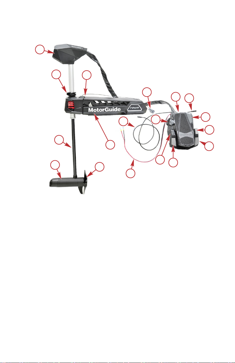
PRODUCT OVERVIEW
Tour Pro 82/Tour Pro 109 MotorGuide Trolling Motor
a - Top housing
b - Depth collar handle
c - Integrated bounce buster (optional)
d - HD+ universal sonar cable (some models)
e - Stow/deploy handle
f - Speed control knob
eng 9
g - Foot pedal
h - NMEA 2000 cable
i - Momentary on button
j - Anchor button
k - Heading lock button
l - Prop on button
m - LED dashboard
n - Battery cables
o - Mount
p - Propeller
q - Lower unit
Page 16

r - Composite column
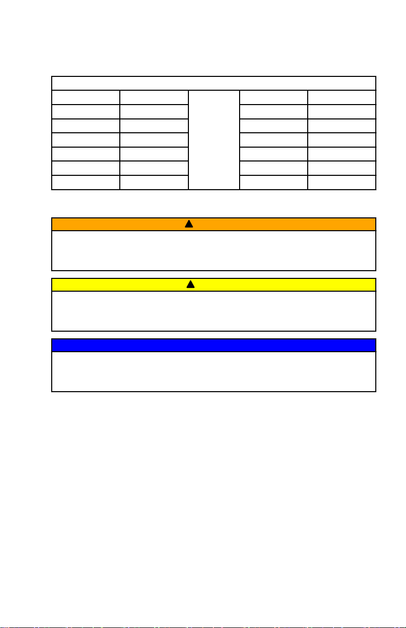
Specifications
Model
TR Pro
82 45"
TR Pro
109 45"
TR Pro
82 45"
HD
+SNR
TR Pro
109 45"
HD
+SNR
Peak
Thrust
82 24 V
109 36 V
82 24 V
109 36 V
PRODUCT OVERVIEW
Speeds
Volts
Control/
Motor
Direction
Digital
Variable/
Forward
Digital
Variable/
Forward
Digital
Variable/
Forward
Digital
Variable/
Forward
Integrated
Sonar
No Yes
No Yes
Yes Yes
Yes Yes
Pinpoint
GPS
Shaft
Length
114.3 cm
(45 in.)
114.3 cm
(45 in.)
114.3 cm
(45 in.)
114.3 cm
(45 in.)
10 eng
Page 17

WIRING AND BATTERY INFORMATION
Wiring and Battery Information
WARNING
!
An operating or charging battery produces gas that can ignite and explode,
spraying out sulfuric acid, which can cause severe burns. Ventilate the area
around the battery and wear protective equipment when handling or servicing
batteries.
WARNING
!
Performing service or maintenance without first disconnecting the battery can
cause product damage, personal injury, or death due to fire, explosion,
electrical shock, or unexpected motor starting. Always disconnect the battery
cables from the battery before maintaining, servicing, installing, or removing
motor components.
Recommended Practice and Procedures
IMPORTANT: Unplug the trolling motor after each use and when charging the
battery.
• Do not use the main engine battery to power the trolling motor. Use a
dedicated trolling motor battery or battery bank.
• Ensure that the batteries are enclosed and secured within a battery box to
prevent accidental shorting of the battery terminals.
• Route the trolling motor wires on the opposite side of the boat from other
boat wiring.
• Connect boat accessories directly to the main engine battery.
• Do not charge the trolling motor batteries while the trolling motor is in the
deployed (down) position.
Battery Recommendations
• Use 12‑volt, deep cycle marine batteries. The number of batteries
required varies according to the model of your trolling motor. Refer to
Battery Connection.
• As a general rule, deep cycle batteries with a higher amp‑hour rating or
reserve capacity rating will provide longer run times and better
performance.
• Install a manual reset circuit breaker in line with the trolling motor positive
leads within 1.8 m (6 ft) of the batteries. These can be purchased from
your local MotorGuide retailer or from www.motorguide.com.
• Do not extend the included 10‑gauge battery cables more than 1.8 m (6 ft)
for a total of 3 m (10 ft). If longer battery cables are required, MotorGuide
offers accessory 8 mm² (8‑gauge) battery cables.
• Use nylock nuts to secure the battery cables to their terminals. Using wing
nuts to secure the battery cables can cause loose connections.
eng 11
Page 18

WIRING AND BATTERY INFORMATION
• Do not power any depth sounders or fish finders from the trolling motor
battery. Connecting electronic equipment to the trolling motor batteries
can cause electrical interference. Any depth sounders or fish finders must
be powered from the engine starting or accessory battery.
Recommended MotorGuide Accessory Description
8‑gauge battery cable and terminals with 50‑amp manual reset circuit breaker
50‑amp manual reset circuit breaker
60‑amp manual reset circuit breaker
Battery Precautions
WARNING
!
An operating or charging battery produces gas that can ignite and explode,
spraying out sulfuric acid, which can cause severe burns. Ventilate the area
around the battery and wear protective equipment when handling or servicing
batteries.
When charging batteries, an explosive gas mixture forms in each cell. Part of
this gas escapes through holes in the vent plugs and may form an explosive
atmosphere around the battery if ventilation is poor. This explosive gas may
remain in or around the battery for several hours after it has been charged.
Sparks or flames can ignite this gas and cause an internal explosion, which
may shatter the battery.
The following precautions should be observed to prevent an explosion:
1. Keep flames away and do not smoke near batteries being charged or
which have been charged recently.
2. Do not disconnect the battery cables while the trolling motor is operating,
because a spark usually occurs at the point where a live circuit is broken.
Always use care to prevent reverse polarization when connecting or
disconnecting cable clamps on chargers. Poor connections are a common
cause of electrical arcs, which cause explosions.
3. Do not reverse the polarity of battery terminal to cable connections.
Wire and Cable Routing
• Route the trolling motor wires on the opposite side of the boat from other
boat wiring.
• The trolling motor should be connected to its own dedicated battery.
• Sensitive electronics, such as depth finders, should be connected to a
separate battery.
• Marine engines should have their own dedicated starting battery.
• All batteries should have a common ground.
12 eng
Page 19
WIRING AND BATTERY INFORMATION
Wire Color Code Abbreviations
Wire Color Abbreviations
BLK Black
BRN Brown GRA Gray
GRN Green ORN Orange
PNK Pink PPL Purple
RED Red TAN Tan
WHT White YEL Yellow
LT Light DK Dark
Battery Connection
WARNING
!
Before working around electrical system components, disconnect the battery
cables from the battery to prevent injury or damage to the electrical system
due to an accidental short circuit.
!
CAUTION
Disconnecting or connecting the battery cables in the incorrect order can
cause injury from electrical shock or can damage the electrical system.
Always disconnect the negative (‑) battery cable first and connect it last.
BLU Blue
NOTICE
Failure to operate the trolling motor within the recommended voltage
specifications can cause product damage. Do not exceed the maximum
supply voltage.
IMPORTANT: Refer to the decal on the head of the trolling motor to determine
the voltage requirements of your trolling motor.
24-VOLT BATTERY CONNECTION
1. Starting with the negative (–) lead, disconnect the battery cables from the
engine starting or accessory battery.
2. Install a 50‑amp (good) or 60‑amp (best) manual reset circuit breaker in
line with the trolling motor power cable positive (+) lead and the trolling
motor battery B positive (+) terminal.
3. Connect the positive (+) trolling motor lead to the positive (+) terminal on
trolling motor battery B.
4. Connect a jumper wire (reference gray) between the negative (–) terminal
on battery B to the positive (+) terminal on battery A.
IMPORTANT: The jumper wire should be the same wire gauge as the
negative (–) and positive (+) power cables.
eng 13
Page 20

RED
BLACK
a
b
c
d
37824
GRAY
c
Battery A
Battery B
WIRING AND BATTERY INFORMATION
5. Connect the trolling motor negative (–) lead to the negative (–) terminal on
battery A.
6. Starting with the positive (+) lead, reconnect the battery cables to the
engine starting or accessory battery.
24-volt battery connection
a - Power cables to trolling motor
b - Manual reset circuit breaker
c - Jumper wire (not supplied)
d - Negative (–) battery terminal
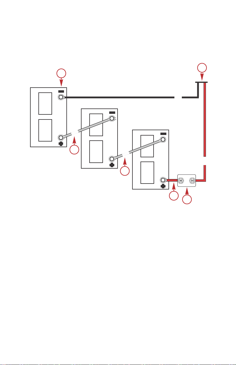
36-VOLT BATTERY CONNECTION
1. Starting with the negative (–) lead, disconnect the battery cables from the
engine starting or accessory battery.
2. Install a 50‑amp (good) or 60‑amp (best) manual reset circuit breaker in
line with the trolling motor power cable positive (+) lead and the trolling
motor battery C positive (+) terminal.
3. Connect the positive (+) trolling motor lead to the positive (+) terminal on
trolling motor battery C.
4. Connect a jumper wire (reference gray) between the negative (–) terminal
on battery C to the positive (+) terminal on battery B.
IMPORTANT: The jumper wire should be the same wire gauge as the
negative (–) and positive (+) power cables.
5. Connect a jumper wire (reference gray) between the negative (–) terminal
14 eng
on battery B to the positive (+) terminal on battery A.
Page 21
RED
BLK
37825
GRY
c
Battery B
Battery C
Battery A
GRY
c
a
b
c
d
WIRING AND BATTERY INFORMATION
6. Connect the trolling motor negative (–) lead to the negative (–) terminal on
battery A.
7. Starting with the positive (+) lead, reconnect the battery cables to the
engine starting or accessory battery.
36-volt battery connection
a - Power cables to trolling motor
b - Manual reset circuit breaker
c - Jumper wire (not supplied)
d - Negative (–) battery terminal
eng 15
Page 22
70055
a
b
70112
TROLLING MOTOR INSTALLATION AND OPERATION
Installing the Steering System on the Mount
IMPORTANT: Do not install the gas spring at this time.
1. Remove the mount from the packaging and leave the mount in the
deployed position.
2. Rest the mount on a level elevated surface such as a workbench.
3. Remove the steering assembly from the packaging.
4. Remove the plastic latch spacer from the mount.
a - Latch spacer
b - Mount
5. Remove the Motorguide Tour mount accessory kit from the packaging.
6. Install the Allen screws on the steering system assembly.
16 eng
Page 23
b
c
a
70056
70007
a
a
bb
TROLLING MOTOR INSTALLATION AND OPERATION
7. Push the plastic retaining washers onto the Allen screws.
a - Steering assembly
b - Plastic retaining washers
c - Allen screws
IMPORTANT: Be careful not to pinch the stow/deploy handle and cable
between the mounting bracket and the steering system.
8. Lower the steering assembly onto the mount vertically from above while
aligning the keyways and the alignment keys.
a - Keyway
b - Alignment keyway
IMPORTANT: Be certain the top of the 360 breakaway housing is aligned with
the top of the mount.
NOTE: The first Allen screw may come loose while tightening the second Allen
screw.
eng 17
Page 24

a
b
b
70008
TROLLING MOTOR INSTALLATION AND OPERATION
9. Tighten one of the two Allen screws to the specified torque. Then tighten
the second Allen screw to the specified torque. When the second Allen
screw is tightened, verify that the first Allen screw is still tightened to the
specified torque.
10. Tighten the two Allen screws to the specified torque.
Description Nm lb‑in. lb‑ft
Allen screws (2) 16.3 144 –
a - Allen screws
b - 360 breakaway housing aligned with the
top of the mount
Trolling Motor Installation
IMPORTANT: It is recommended that the motor be mounted as far forward on
the boat as possible.
Make sure there is nothing obstructing the stowing or deploying of the motor in
and out of the water.
Make sure there are no obstructions underneath the mount to prevent damage
to wires or other obstructions under the hull.
1. Stow the fully assembled motor by pulling on the stow/deploy handle and
raising the motor into the stowed position.
18 eng
Page 25

70015
a
b
b
c
TROLLING MOTOR INSTALLATION AND OPERATION
2. Install the tie‑down strap through the slots in the mount, hook‑and‑loop
side down, with the buckle facing toward the outside of the boat.
a - Tie‑down strap
b - Slots
c - Buckle
IMPORTANT: If planning to install the provided bounce buster ensure that the
bounce buster contacts the boat on a desired location prior to drilling holes
and mounting the motor. Refer to Bounce Buster Installation.
IMPORTANT: A minimum of four mounting bolts are required to mount the
trolling motor to the boat. Spread the mounting bolts as far apart as practical
for the most secure mounting.
3. Place the trolling motor on the surface of the boat deck. Use the mount as
a template to mark the locations of the front mounting holes and the rear
mounting holes on the mount.
Installation Variations
For a new boat installation Use the exposed 7.6 cm (3 in.) hole pattern.
If replacing an existing trolling
motor that uses a 3" hole
pattern
Use the exposed 7.6 cm (3 in.) hole pattern
in the base of the mount.
eng 19
Page 26

b
b
b
b
b
b
a
a
a
a
a
a
c
70119
TROLLING MOTOR INSTALLATION AND OPERATION
Installation Variations
Remove the four screws and starboard side
If replacing an existing trolling
motor that uses a 4" hole
pattern
a - 7.6 cm (3 in.) pattern
b - 10.2 cm (4 in.) pattern
c - Starboard side cover
IMPORTANT: Use a countersink drill bit or a larger drill bit to countersink the
holes on fiberglass boats to prevent cracking.
4. Drill the mounting holes with a 7 mm (1/4 in.) diameter drill bit. Remove
any debris.
5. Insert the rubber isolators between the base of the mount and the boat
mounting surface.
6. Install the stainless steel washers and nylon locknuts onto the mounting
screws underneath the boat deck. Tighten the screws securely.
cover plate from inside of the mount to
uncover the 10.2 cm (4 in.) mounting hole
pattern that matches the legacy MotorGuide
trolling motor mounts.
20 eng
Page 27

a
b
c
d
e
f
58753
TROLLING MOTOR INSTALLATION AND OPERATION
IMPORTANT: To prevent galling of the mounting hardware, do not use a drill
to tighten the mounting screws.
If necessary, shim the rubber washers with 25 mm (1 in.) outside diameter
stainless steel washers to create a level mounting surface.
The mount bracket must lay flush against the rubber isolators before being
bolted to the deck or the mount will bind, making it difficult or impossible to
unlatch.
a - Mount bracket
b - Mounting screw
c - Rubber isolator
d - Deck
e - Washer
f - Nylon locknut
7. Once installed, the bracket should fasten securely and evenly, and
release with a light, quick pull on the stow/deploy handle.
Permanent Foot Pedal Mounting—Optional
1. Determine a suitable location for the foot pedal with the trolling motor
deployed and in the stowed position. Ensure that there are no
obstructions beneath the boat deck that would interfere with the mounting
screws, such as bulkheads or boat wiring.
2. Once a suitable location is chosen, mark the mounting holes, using the
foot pedal as a template.
IMPORTANT: To prevent cracking, use a countersink drill bit or a larger drill
bit to countersink the holes on fiberglass boats.
3. Use a 3 mm (7/64 in.) drill bit to drill holes through the boat deck.
NOTE: Make sure the cables and cable sheathing are not kinked or twisted
before mounting to the boat deck.
4. Use three #8 x 2 in. stainless steel screws to secure the foot pedal to the
boat deck.
5. Push the pedal into the full toe down position and install the two front
screws on the foot pedal.
eng 21
Page 28

a
b
70278
70125
a
TROLLING MOTOR INSTALLATION AND OPERATION
6. Push the pedal into the full heel down position and install the rear screw
on the foot pedal.
a - Rear screw
b - Front screws (2)
Bounce Buster Installation
1. Place the trolling motor in the stowed position.
2. Remove the bounce buster from the mounting accessory kit.
!
CAUTION
Avoid injury from parts flying into the passenger compartment of the boat. If
the bounce buster is not correctly installed, the trolling motor can
inadvertently deploy, which at planning speed could result in catastrophic
failure of the trolling motor. Check that the stow latch fully engages after
installation of the bounce buster.
3. Measure the distance between the boat deck and the outside surface of
the mounting bracket.
a - Distance between the boat deck and the
outside surface of the mounting bracket.
4. Add 6.35 mm (1/4 in.) to the measured length (distance between the boat
deck and the outside surface of the mounting bracket) taken in the
previous step.
22 eng
Page 29

b
70135
d
a
c
a
c
b
70137
TROLLING MOTOR INSTALLATION AND OPERATION
5. Cut the bounce buster to the new measurement on the non‑assembled
end of the bounce buster.
a - Distance between the boat deck and outside surface of the mounting
bracket
b - Non‑assembled end
c - Add 6.35 mm (1/4 in.)
d - Bounce buster
6. Move the trolling motor into the deployed position.
NOTE: Removing the steering system from the deployed mount will allow for
easier tightening of the bounce buster screw.
NOTE: The bounce buster will loosen if not fully seated in the bounce buster
pocket.
7. Using the non‑assembled end of the bounce buster, slide the bounce
buster into the bounce buster pocket.
8. Use a pencil or piece of tape to mark a line to indicate when bounce
buster is fully seated in the bounce buster pocket. Mark the line 20 mm
(0.79 in.) from the cut end of the bounce buster.
9. Insert and tighten the bounce buster self‑tapping screw into the bounce
buster pocket.
a - Bounce buster pocket
b - Self‑tapping screw
c - Bounce buster
eng 23
Page 30

70020
a
b
c
d
70138
TROLLING MOTOR INSTALLATION AND OPERATION
NOTE: Install the steering system if removed. Refer to
System on the Mount
10. Stow the trolling motor.
11. Adjust the boot end of the bounce buster by removing the rubber boot,
loosen the jam nut by turning the screw counter clockwise to the desired
length.
12. Tighten the jam nut to the base of the bounce buster followed by a
clockwise turn.
13. Replace the rubber boot.
a - Bounce buster
b - Jam nut
c - Screw
d - Rubber boot
.
Installing the Steering
14. Verify in the stowed position that the stow latch is engaged by lifting up on
the 360 breakaway without the use of the stow/deploy handle. If the stow
latch is engaged, the mount will not release. If mount releases, repeat
Step 9 until Step 10 can be verified.
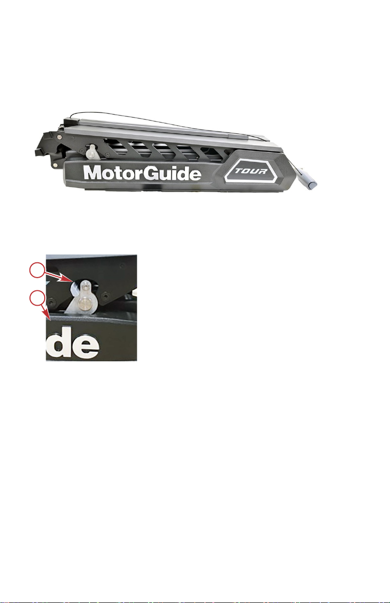
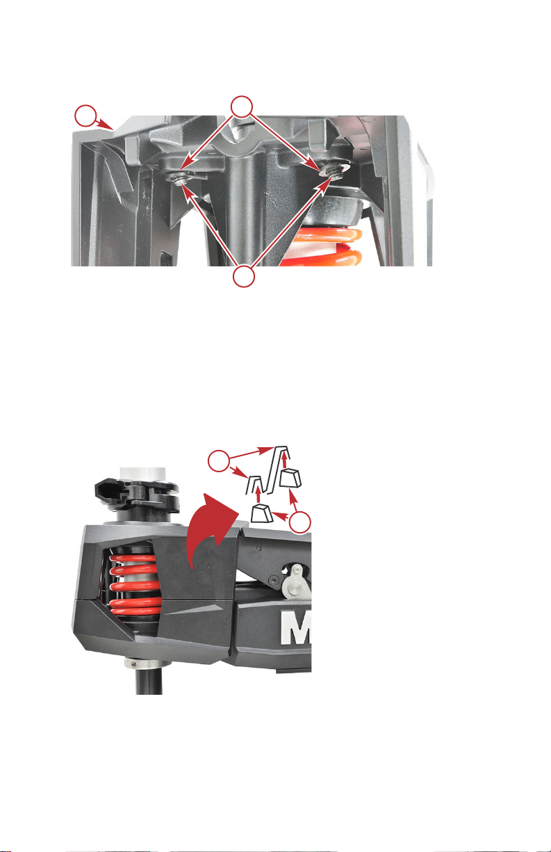
Installing the Gas Spring
1. Remove the gas spring from the Accessory Kit located in the packaging.
2. Rotate the motor into the stowed position until the ball end studs align
with the gas spring end fittings.
IMPORTANT: Do not install the gas spring with the rod end up. This can result
in premature gas spring failure.
3. Push or squeeze the piston end fitting of the gas spring onto the ball stud
located on the inner arm of the mount.
24 eng
Page 31

a
b
c
b
d
e
70140
TROLLING MOTOR INSTALLATION AND OPERATION
4. Repeat the previous step for the rod end fitting of the gas spring onto the
ball stud located on the base of the mount.
a - Piston end fitting
b - Ball stud
c - Gas spring
d - Rod end fitting
e - Mount
5. Deploy the motor fully to ensure the gas spring operates correctly.
6. Fully stow the motor.
7.
Refer to Tour Pro Pedal Resistance Settings to customize the feel of
resistance on the pedal using the remote.
NMEA 2000 Pinpoint Connection
The NMEA 2000 Chartplotter integration connecting Tour Pro via a NMEA 2000
network will enable on‑screen control and motor status by using the Pinpoint
GPS features such as Anchor Lock, Jog, Heading Lock, Cruise Control
on‑screen as well as following custom drawn routes, go‑to waypoint,
programmable turns and more.
INSTALLATION
1. Remove the NMEA 2000 T‑connector from the accessory kit.
NOTE: A 182.9 cm (6 ft.)drop cable may be used between the foot pedal
connection and the provided T‑connector to reach an existing NMEA 2000
network if the provided cable length at the foot pedal will not reach.
eng 25
Page 32

a
b
70279
TROLLING MOTOR INSTALLATION AND OPERATION
2. Connect the middle male port to the NMEA 2000 cable that is coming out
of the Tour Pro foot pedal.
a - NMEA 2000 cable
b - NMEA 2000 T‑connector
3. Attach the T‑connector to an existing NMEA 2000 network backbone. If
no existing network exists, purchase MotorGuide NMEA 2000 Starter Kit
(Part #8M0107522).
4. Use a termination resistor to cap off the remaining open connector end of
the T‑Connector if it is the last T in a NMEA 2000 network.
Connecting the Sonar Display to the Trolling Motor
NOTE: This procedure applies only to models equipped with integrated HD+
universal sonar.
This sonar display connection procedure applies to trolling motor models with
internal sonar that offer built‑in 83/200 and 455/800 kHz HD+ universal sonar
transducers compatible with Garmin®, Humminbird®, Lowrance®, and
Raymarine® brand sonar displays. For compatibility with other sonar units,
refer to www.motorguide.com.
26 eng
Page 33

a
70141
TROLLING MOTOR INSTALLATION AND OPERATION
The trolling motor is equipped with a MotorGuide HD+ universal sonar plug.
Adapters are available to connect other brands of sonar displays to the trolling
motor. Match the cable connector to the sonar port on the back of the sonar
display. Some sonar multi‑functional displays may require additional cables
provided by the sonar manufacturer. Power up the unit to ensure that the sonar
cable is connected securely.
a - Harness—to nose cone sonar
Transducer adapter cables available from MotorGuide Part Number
Lowrance® 9‑Pin HD+ Sonar Adapter Cable 8M4004174
Lowrance® 7‑Pin HD+ Sonar Adapter Cable 8M4004175
Humminbird® 11‑Pin HD+ Sonar Adapter Cable 8M4004176
Humminbird® 7‑Pin HD+ Sonar Adapter Cable 8M4004177
Garmin® 8‑Pin HD+ Sonar Adapter Cable 8M4004178
Raymarine® HD+ Element Sonar Adapter Cable 8M4004179
Raymarine® HD+ Axiom Sonar Adapter Cable 8M4004180
MotorGuide 15' HD+ "Universal Sonar Extension Cable 8M4004245
Reducing Sonar Transducer Interference
Sonar transducers can be affected by interference, such as radio frequency
interference (RFI) and electromagnetic interference (EMI). This interference
can cause undesired operation of the sonar display. Refer to the following list to
reduce sonar interference sources.
1. Lower the sonar sensitivity, also known as gain. Refer to the documents
included with your sonar display.
a. Change the sensitivity to an automatic setting.
b. If the automatic setting does not reduce sonar interference, manually
change the sensitivity to 55–65% of the maximum setting.
2. Verify that the transducer cable is not routed near any power cables.
3. Ensure that the positive (+) and negative (–) power cables are installed
next to each other. This helps cancel any EMI.
4. Inspect the transducer cable for damage, nicks, or cuts. Replace the
transducer cable if it is damaged.
eng 27
Page 34

70022
TROLLING MOTOR INSTALLATION AND OPERATION
5. Connect the sonar display to a separate accessory battery with only the
sonar display connected. This will verify if the interference is coming from
the power cables or the transducer cable.
a. If the interference stops when the sonar display is connected to a
separate accessory battery, inspect the boat wiring. Most likely, there
is a problem with the ground (–) connection. All devices should have a
common ground.
b. If the interference continues, it is likely coming from the transducer or
transducer cable.
6. Install a radio frequency (RF) choke onto the sonar display power cable.
7. Connect the sonar display to a different transducer.
Cable Routing Clip Installation
NOTE: The cable routing clips are intended to be used with externally routed
trolling motor accessories that require cables to be routed on the outside of the
shaft of the motor and alongside the mount for a seamless installation on the
trolling motor.
1. Place the motor in the deployed position.
2. After mounting the accessory of choice on the shaft or lower unit of the
motor run the cable on the side of the shaft to the bottom of the 360
breakaway housing.
3. Attach the cable to the bottom of the 360 breakaway housing using the
provided zip tie and screw found in the trolling motor accessory kit.
4. Route the cable from the bottom of the 360 breakaway housing to the top
of the 360 breakaway housing using the zip tie and screw.
5. Insert the cables of the accessory into the front of the cable routing clip
and out of the second slot on the opposite end of the clip.
28 eng
Page 35

2.54 cm
(1 in.)
a
d
e
c
b
f
70156
TROLLING MOTOR INSTALLATION AND OPERATION
IMPORTANT: The clip must be within 2.54 cm (1 in.) of the raised part of the
side plate to avoid damage to the clip when stowing and deploying.
6. Insert the clip, open side up, into the overhang on the top of either side of
the trolling motor mount.
a - Cable routing clip
b - Overhang
c - Top of 360 breakaway housing
d - Bottom of 360 breakaway housing
e - 360 breakaway housing
f - Cable
Stowing the Trolling Motor
WARNING
!
Rotating propellers can cause serious injury or death. Never start or operate
the motor out of water.
!
CAUTION
Moving parts, such as hinges and pivot points, can cause serious injury.
Keep away from moving parts when stowing, deploying, or tilting the motor.
IMPORTANT: Raise the trolling motor out of the water. While holding the
release handle allow the trolling motor to fall into the stow latched position from
the 90° position. Do not release the latch release handle until the stow latch is
engaged.
1. Firmly grasp the stow/deploy handle.
2. Snap the stow/deploy handle to deploy the latch hooks.
eng 29
Page 36

a
70019
70021
b
c
d
e
a
TROLLING MOTOR INSTALLATION AND OPERATION
3. Continue to pull the stow/deploy handle to raise the lower unit onto the
mount.
a - Stow/deploy handle
4. Once the motor is in the stowed position, the stow latch engages to
secure the trolling motor.
a - Mount
b - Tie‑down strap
c - Buckle
d - Composite column
e - Motor
5. Position the tie‑down strap over the composite column and through the
buckle. Pull it tight, then secure the hook‑and‑loop backing together to
secure the motor to the mount.
Deploying the Trolling Motor
WARNING
!
Rotating propellers can cause serious injury or death. Never start or operate
the motor out of water.
30 eng
Page 37

a
70019
TROLLING MOTOR INSTALLATION AND OPERATION
!
CAUTION
Moving parts, such as hinges and pivot points, can cause serious injury.
Keep away from moving parts when stowing, deploying, or tilting the motor.
!
CAUTION
Avoid possible serious injury from the motor dropping suddenly when
adjusting the motor depth. Firmly grasp the motor shaft with one hand when
raising or lowering the motor.
1. Release the tie‑down strap that is securing the composite shaft to the
mount.
2. Firmly grasp the stow/deploy handle.
3. Pull the latch stow/deploy handle to disengage the stow latch.
IMPORTANT: Lower the trolling motor into the water. Release the stow/deploy
handle allowing the gas spring to ease the motor into the deployed position.
a - Stow/deploy handle
IMPORTANT: Make sure the deploy latches are engaged before operating the
motor.
eng 31
Page 38

70022
TROLLING MOTOR INSTALLATION AND OPERATION
4. Once the motor is in the deployed position, the deploy latch hooks will
engage to secure the trolling motor.
Adjusting the Trolling Motor Depth
!
CAUTION
Avoid possible serious injury from dropping the motor when adjusting the
motor depth. Firmly grasp the motor shaft with one hand when raising or
lowering the motor.
Adjust the depth of the motor to improve trolling motor performance in various
water depths and wave conditions.
IMPORTANT: When adjusting the motor depth, ensure that the propeller
blades are fully submerged 15–30 cm (6–12 in.) below the water surface to
avoid cavitation.
1. Firmly grasp the outer column with one hand.
2. Pull open the cam lock arm until the outer column slides freely.
3. Raise or lower the outer column until the propeller blades are submerged
15–30 cm (6–12 in.) below the water surface.
IMPORTANT: Make sure there is nothing obstructing the operation of the cam
lock lever.
32 eng
Page 39

a
b
70023
TROLLING MOTOR INSTALLATION AND OPERATION
4. Rotate the cam lock lever until the depth collar binds tightly on the outer
column, then close the cam lock arm.
a - Cam lock lever
b - Outer column
Directional Indicator
The indicator provides directional information at a glance.
1. To make a right turn, press the toe down. The motor steers the boat to the
right.
2. To forward direction, place the foot pedal in neutral position.
3. To make a left turn, press the heel down. The motor steers the boat to the
left.
eng 33
Page 40

c
b
d
70024
a
TROLLING MOTOR INSTALLATION AND OPERATION
4. To reverse direction, continue to press the toe or heel all the way down to
point the lower unit toward the back of the boat to move the boat in
reverse.
a - Directional indicator
b - Right turn ‑ toe down
c - Straight ahead ‑ foot pedal in neutral position
d - Left turn ‑ heel down
Pinpoint GPS Overview
TROLLING MOTOR INSTALLATION GUIDELINES
This section covers important guidelines for your Tour Pro trolling motor. Refer
to the following list of important considerations:
Verify that objects containing iron (such as anchors) are not located within
91.4 cm (36 in.) of the trolling motor.
34 eng
Page 41

62194
a
b
c
d
d
TROLLING MOTOR INSTALLATION AND OPERATION
Keep unnecessary wiring and power cables away from the trolling motor.
Verify that the trolling motor power cables are bundled together. Do not
route the power cables separately, particularly within 91.4 cm (36 in.) of
the trolling motor. Routing the power cables together reduces
electromagnetic interference.
Obstructions such as mountain ranges, bridges, tall trees, buildings, and
severe weather can affect the GPS signal strength.
GPS signal strength can be affected by certain geographic locations, such
as southern or northern polar extremes like Alaska and northern Canada.
!
CAUTION
Avoid injury or property damage due to unintended operation. Certain objects
—especially magnetic metal objects, such as anchors—can affect the GPS
system if they are within or passing through the magnetic field surrounding
the trolling motor. Objects obstructing the GPS signal can also have a
negative effect on system operation. Be mindful of objects close to the trolling
motor, and use care when operating the trolling motor in a GPS‑guided
mode.
Objects and locations may obstruct the GPS signal
a - Trees
b - Severe weather
c - Mountains
d - Extreme Northern and Southern locations
eng 35
Page 42

62195
+
-
a
15.2 cm (6 in.)
b
a
54153
c
b
TROLLING MOTOR INSTALLATION AND OPERATION
Objects may cause disturbance to the magnetic field within 91 cm (36 in.)
of the trolling motor
a - Objects containing iron (such as anchors)
b - Trolling motor power cables (install no more than 15.2 cm [6 in.] apart)
LINKING THE HANDHELD REMOTE TO THE TROLLING MOTOR
The first time the trolling motor is powered up, the handheld remote will need to
be linked to the trolling motor. The linking procedure is listed as follows:
1. Deploy the trolling motor.
2. Starting with the positive (+) lead, connect the trolling motor power cables
to the battery.
3.
Within ten seconds after connecting the power cables, press and hold
the left arrow button and right arrow button on the handheld remote at
the same time. The trolling motor will emit a low tone to confirm that the
handheld remote has been linked to the trolling motor.
a - Left arrow button
b - Propeller button
c - Right arrow button
If you wish to clear the linked handheld from the trolling motor's memory,
connect the battery cables to a power source such as the trolling motor battery
or power receptacle, and in less than ten seconds press the left arrow, right
arrow, and propeller buttons at the same time. You will need to complete the
link procedure again to use the handheld remote with the trolling motor.
36 eng
Page 43

a
b
c
d
e
70333
a
70378
TROLLING MOTOR INSTALLATION AND OPERATION
If you are having trouble syncing your remote, start with the motor unplugged
and deployed. Hold down the left arrow, right arrow, and propeller buttons at
the same time before you plug in the motor. Once the battery light turns green,
let go of the buttons and the link process should be complete.
MOUNTING ANGLE CALIBRATION
IMPORTANT: This calibration is required and must be completed. It should be
repeated when the trolling motor is moved from one boat to another. This
calibration can be done with the boat in or out of the water.
a - Left turn
b - Right turn
c - Manual mode
d - #3 button
e - #1 button
IMPORTANT: A fixed GPS position is required to complete the mounting angle
calibration. The Pinpoint GPS system will emit an audible tone once it has
acquired a fixed GPS position (in the default audio mode), and the GPS status
indicator light will illuminate on the LED dashboard located on the foot pedal.
a - GPS navigation indicator light
1. Power up and deploy the trolling motor. Adjust the motor height so that
the bottom of the head is 15.2 cm (6 in.) above the depth collar and the
motor is clear of any obstructions while turning.
IMPORTANT: Stay a safe distance away from the propeller when the trolling
motor is in an operational mode.
eng 37
Page 44

54441
b
a
cc
TROLLING MOTOR INSTALLATION AND OPERATION
WARNING
!
Rotating propellers can cause serious injury or death. Never start or
operate the motor out of water.
2.
Use the left turn and right turn buttons to steer the unit so that it is
facing straight ahead, parallel with the keel of the boat, with the nose cone
of the lower unit facing forward and the propeller facing aft.
View of boat from above
a - Nose cone facing the bow
b - Propeller facing the stern
c - Parallel lines
3. Once the lower unit is positioned as close to parallel with the keel as
possible, press and hold the manual mode button, then press and
release the 1, 1, then 2 buttons in sequence. The trolling motor will emit
an audible tone, flash the status indicator light, and then return to manual
mode, completing the mounting angle calibration.
COMPASS CALIBRATION
IMPORTANT: This calibration is completed at the factory. It should be repeated
at the time of installation, if the Pinpoint GPS system is not performing as
expected, or if you have traveled a long distance from the last point of
calibration. This calibration may be done with the boat in the water using the
primary propulsion engine, or with the boat on the trailer. If the boat is on the
trailer, tow the boat in two circles. Two beeps will occur when very close to
completing the second circle. Listen for the tone to acknowledge a successful
calibration. The GPS light will turn off after command M111 is accepted. The
GPS light will turn on and a beep will occur, signaling a successful calibration.
IMPORTANT: A fixed GPS position is required to complete the compass
calibration. The Pinpoint GPS system will emit an audible tone once it has
acquired a fixed GPS position (in the default audio mode), and the GPS status
indicator light will illuminate.
38 eng
Page 45

53737
b
a
TROLLING MOTOR INSTALLATION AND OPERATION
IMPORTANT: GPS signal strength may vary, depending on satellite reception.
This can affect GPS performance.
a - Manual mode
b - #1 button
1. a.
2. Deploy the trolling motor. Adjust the motor height so that the bottom of the
3.
4. a.
5. Two beeps will occur when very close to completing the second circle.
If performing the compass calibration with the boat in the water:
locate a suitable area clear of obstructions to navigation (both above
and below the waterline) to perform the compass calibration.
b.
If performing the compass calibration with the boat on the trailer:
locate a suitable area clear of obstructions to perform the compass
calibration.
head is 15.2 cm (6 in.) above the depth collar and the motor. If performing
the compass calibration with the boat in the water, verify that you are in a
location where your trolling motor and primary propulsion engine will not
hit bottom or other obstructions.
Press and hold the manual mode button, then press 1, 1, 1. The trolling
motor will emit three ascending‑tone beeps and the GPS status indicator
light will turn off.
If performing the compass calibration with the boat in the water:
use the primary propulsion engine to slowly drive the boat in two
complete circles.
b.
If performing the compass calibration with the boat on the trailer:
tow the boat in two complete circles.
The GPS status indicator light will turn on and a beep will occur, signalling
a successful compass calibration.
eng 39
Page 46

a
54148
b
c
d
e
TROLLING MOTOR INSTALLATION AND OPERATION
PINPOINT ALIGNMENT CALIBRATION
IMPORTANT: This calibration is required and must be completed. It should be
repeated when the trolling motor is moved from one boat to another. This
calibration can be done with the boat in or out of the water.
a - Left turn
b - Right turn
c - Manual mode
d - #3 button
e - #1 button
IMPORTANT: A fixed GPS position is required to complete the pinpoint
alignment calibration. The Pinpoint GPS system will emit an audible tone once
it has acquired a fixed GPS position (in the default audio mode), and the GPS
status indicator light will illuminate.
1. Power up and deploy the trolling motor. Adjust the motor height so that
the bottom of the head is 6 inches above the depth collar and the motor is
clear of any obstructions while turning.
IMPORTANT: Stay a safe distance away from the propeller when the trolling
motor is in an operational mode.
WARNING
!
Rotating propellers can cause serious injury or death. Never start or
operate the motor out of water.
2. Use the left turn and right turn buttons to steer the unit so that the lower
unit is parallel to the head, with the nose cone of the lower unit facing
forward and the propeller facing aft.
RESET TO FACTORY CALIBRATION
To reset the trolling motor to the factory calibration, press and hold the manual
mode button, then press 1, 1, 4.
Operating the Pinpoint GPS System
STATUS INDICATOR LIGHT IDENTIFICATION
This trolling motor is equipped with a multifunction status indicator light panel. It
can display the status of the motor, propeller, battery charge, and GPS status
for quick and easy reference during operation.
40 eng
Page 47

a
b
c
d
70335
TROLLING MOTOR INSTALLATION AND OPERATION
• Lights and functions:
a. The Power indicator LED will illuminate when power is connected to
the trolling motor.
b. The Propeller LED will flash on and off when the Prop button is
pressed or when a GPS function requiring the propeller to be on is
activated indicating that the prop is moving.
c. The GPS navigation LED will illuminate as a solid light when GPS
satellite is acquired and will flash when a GPS function is engaged
and in use.
d. The Battery Status LED will display battery level goes down the light
will go from Green to Red to Flashing Red indicating Critical low
battery.
a - Power on/off indicator light
b - Propeller on/off indicator light
c - GPS navigation indicator light
d - Battery status light
PINPOINT GPS STARTUP
The global positioning system (GPS) is a satellite‑based navigation system
capable of providing positional information anywhere on Earth, provided that
the GPS receiver has a clear line of sight to at least four GPS satellites.
When the trolling motor is powered up and deployed, it is immediately capable
of operating as a conventional trolling motor. The trolling motor will require
between 30 seconds to 10 minutes to acquire a fixed GPS position, depending
on how much time has passed since the unit was powered up. Having a clear
view of the sky overhead, with no large trees, power lines, bridges, mountain
ranges, or buildings to interfere with the GPS signal, will improve the GPS
accuracy and reduce the amount of time required to obtain a fixed GPS
position. Once the unit has acquired a fixed GPS position, the GPS accuracy
will continually improve for several minutes. It is recommended to power up the
trolling motor as soon as possible before operation to allow the fixed GPS
position to become as accurate as possible.
Power up the trolling motor by connecting the battery cables to the trolling
motor batteries, or plugging the trolling motor into the trolling motor power plug
(if equipped). The trolling motor will emit audio signals to make the operator
aware of its status.
• The trolling motor will emit one beep when it is powered up.
eng 41
Page 48

a
53017
b
c
d
e
f
TROLLING MOTOR INSTALLATION AND OPERATION
• The trolling motor will emit a three‑beep tune once it has acquired a fixed
GPS position, and the GPS status indicator light will illuminate.
NOTE: Areas near the North and South poles, remote Northern areas, bridges,
severe weather, mountain ranges, and other large obstructions may affect the
GPS signal strength.
OPERATING IN MANUAL MODE
In manual mode, the trolling motor operates like a conventional trolling motor. It
allows the operator to manually control the direction of travel and thrust level of
the trolling motor, using the directional controls on the handheld remote foot
pedal. Refer to the following illustration and instructions to operate the trolling
motor in manual mode with the handheld remote.
Once the trolling motor is powered up, it is ready to operate in manual mode.
Manual mode is the default mode after power‑up, and also if the GPS signal is
lost while in a GPS operating mode. If the GPS signal is lost, the GPS indicator
light will turn off. The trolling motor will emit one beep to indicate its status in
manual mode. To enter manual mode from another mode, press the manual
mode button.
a - Left turn
b - Propeller on/off
c - Increase speed
d - Right turn
e - Manual mode
f - Decrease speed
Turning the Handheld Remote On or Off
The handheld remote is always on, and is ready for use anytime that the trolling
motor is powered up and in the deployed position.
Steering
•
To turn left, press the left turn button on the handheld remote.
•
To turn right, press the right turn button on the handheld remote.
• The available steering range allows the trolling motor to turn beyond 180°
for operation in reverse.
Speed Control
•
Press the propeller on/off button once to start the propeller, and press
the propeller on/off button again to stop the propeller.
42 eng
Page 49

TROLLING MOTOR INSTALLATION AND OPERATION
• The trolling motor will emit a two‑beep tone when the propeller is started,
and the propeller status indicator light on the trolling motor will illuminate.
• The trolling motor will emit a two‑beep tone when the propeller is stopped,
and the propeller status indicator light will turn off.
•
The system is equipped with 20 speed levels. Press the increase speed
(+) button to increase motor speed by one level, and press the decrease
speed (–) button to reduce the motor speed by one level.
•
Holding the increase speed (+) or decrease speed (–) buttons will cause
the speed level to increase or decrease until the speed level is reached.
Holding the increase speed (+) or decrease speed (–) button for 2.5
seconds will increase the speed level from 0% to 100%, or decrease from
100% to 0%, respectively. The trolling motor will emit a two‑beep tone
when it reaches the 100% or 0% speed level.
• The trolling motor will emit a two‑beep tone if the user tries to increase or
decrease the motor speed beyond its limits.
OPERATING IN ANCHOR MODE
Anchor Mode
Anchor mode allows the boat's bow to remain in a fixed location, and will
automatically account for wind and current changes to keep the boat in the
selected location, using the trolling motor steering and speed controls. In order
for anchor mode to operate, the Pinpoint GPS system must have achieved a
fixed GPS location, indicated by the trolling motor emitting a three‑beep tone,
and when achieved the GPS status indicator light will illuminate.
WARNING
!
Avoid serious injury from colliding with other boats, running aground, or
striking objects in the water. The Pinpoint GPS system cannot detect other
boats, shallow water, or objects in the water. Always beware of possible
obstructions to navigation when operating in any Pinpoint GPS mode.
eng 43
Page 50

70336
53018
a
b
TROLLING MOTOR INSTALLATION AND OPERATION
WARNING
!
A spinning propeller, a moving boat, or any solid device attached to the boat
can cause serious injury or death to swimmers. Stop the trolling motor
immediately whenever anyone in the water is near your boat.
a - Anchor mode
b - Manual mode
Anchor button
44 eng
Page 51

TROLLING MOTOR INSTALLATION AND OPERATION
!
CAUTION
Avoid injury or property damage due to unintended operation. Certain objects
—especially magnetic metal objects, such as anchors—can affect the GPS
system if they are within or passing through the magnetic field surrounding
the trolling motor. Objects obstructing the GPS signal can also have a
negative effect on system operation. Be mindful of objects close to the trolling
motor, and use care when operating the trolling motor in a GPS‑guided
mode.
Setting the Anchor
Press the anchor mode button on the handheld remote or foot pedal to place
the system in anchor mode. When the anchor mode button is pressed, the
system will lock onto the fixed GPS position at the moment that the button was
pressed. The trolling motor will emit one ascending chirp to indicate its status in
anchor mode, and the GPS status indicator light will blink slowly.
While anchor mode holds the boat in the selected position, the boat may rotate
or pivot around the trolling motor's steering axis. The orientation of the boat will
follow the wind and/or current.
Exiting Anchor Mode
Exiting anchor mode from the foot pedal, press toe or heel down on the foot
pedal, press the momentary button, or press the anchor mode button again.
Exiting anchor mode using the remote, press the manual mode button or the
anchor mode button. The trolling motor will emit a descending chirp and the
GPS status indicator light on the trolling motor will stop blinking and remain on.
eng 45
Page 52

a
54151
b
c
d
+
_
a
b
c
d
TROLLING MOTOR INSTALLATION AND OPERATION
Adjusting the Anchor Position
a - Left turn—"jog" left
b - Increase speed—"jog" ahead
c - Right turn—"jog" right
d - Decrease speed—"jog" behind
Once the trolling motor is in anchor mode, the anchor position can be adjusted
by pressing the left turn, right turn, increase speed (+), or decrease speed
(–) buttons. Pressing any of these buttons once will adjust the anchor position
by five feet in the direction selected, relative to the boat's heading. For
example, pressing the + button once will move the anchor position forward of
the bow by five feet.
Avoid injury or property damage due to unintended operation. Certain objects
—especially magnetic metal objects, such as anchors—can affect the GPS
system if they are within or passing through the magnetic field surrounding
the trolling motor. Objects obstructing the GPS signal can also have a
negative effect on system operation. Be mindful of objects close to the trolling
motor, and use care when operating the trolling motor in a GPS‑guided
mode.
!
CAUTION
46 eng
Page 53

54420
a
TROLLING MOTOR INSTALLATION AND OPERATION
NOTE: Pressing a button multiple times will move the anchor position five feet
for each time the button is pressed.
Storing or Overwriting an Anchor Position
a - Memory buttons (1–8)
NOTE: An anchor position can be stored or overwritten from any operating
mode except route record mode.
To store an anchor location, press and hold any of the numbered memory
buttons for two seconds. The unit will emit a tone to indicate that the anchor
position has been stored successfully.
Stored anchor positions cannot be erased, but you can overwrite (record over)
them. A stored anchor position can be overwritten by simply storing a new
anchor position to the desired memory button.
Recalling a Stored Anchor Position
NOTE: A stored anchor position can be recalled from any operating mode.
To recall a stored anchor position, press and release the desired memory
button. The trolling motor will emit an ascending chirp to indicate that a stored
anchor position has been retrieved. If the selected anchor position button does
not have a stored anchor position, or if the anchor location is over one mile
away from your current location, the trolling motor will emit an error tone.
IMPORTANT: If the trolling motor loses the GPS signal while in any GPS
mode, the trolling motor will emit an error tone and automatically return to
manual mode.
IMPORTANT: When recalling a stored anchor position, the system will
calculate a straight‑line course from your current position to the selected
anchor position. Ensure that there are no obstructions to navigation between
your location and the selected anchor position—the system will recall an
anchor point even if obstructions are present. If obstructions are encountered,
navigate around them by operating in manual mode.
eng 47
Page 54

54421
a
b
c
TROLLING MOTOR INSTALLATION AND OPERATION
WARNING
!
Avoid serious injury from colliding with other boats, running aground, or
striking objects in the water. The Pinpoint GPS system cannot detect other
boats, shallow water, or objects in the water. Always beware of possible
obstructions to navigation when operating in any Pinpoint GPS mode.
Course shown has an obstruction to navigation
a - Current position of the boat
b - Obstruction to navigation
c - Selected anchor position
HEADING LOCK MODES OF OPERATION
The Pinpoint GPS system is capable of operating in two different heading lock
modes. These modes are:
• Heading lock—course mode (default mode)
• Heading lock—compass mode
When heading lock—course mode is selected, the trolling motor will achieve
lock and navigate along the trolling motor's heading, and compensate for
current, tide, and wind conditions. While in this mode, the operator can adjust
the speed and the heading by using the handheld remote or foot pedal. This is
the default heading lock mode.
48 eng
Page 55

61241
a
b
c
d
TROLLING MOTOR INSTALLATION AND OPERATION
When heading lock—compass mode is selected, the trolling motor will drive
the boat along the trolling motor's compass heading. The boat will drift with the
wind, tide, and current, but the trolling motor will maintain a constant compass
heading. The operator can adjust the speed and the heading by using the
handheld remote or foot pedal.
a - Current position of the boat
b - Direction of wind or current
c - Boat traveling in heading lock—course mode (adjusting for the wind,
tide, and current)
d - Boat traveling in heading lock—compass mode (trolling motor
maintains a constant heading, boat drifts with the wind, tide, and
current)
Both heading lock modes offer advantages to the angler. You can tailor the bait
presentation depending on the species of fish, type of bait, underwater terrain,
structures, water depth, or environmental conditions. MotorGuide recommends
that you experiment with each heading lock mode in different conditions to
learn what works best for you.
The operator can toggle between either heading lock modes. Refer to the
following procedures for operating instructions and how to toggle between each
mode.
eng 49
Page 56

70337
61242
a
c
d
b
e
f
h
g
TROLLING MOTOR INSTALLATION AND OPERATION
OPERATING IN HEADING LOCK—COURSE MODE
When heading lock—course mode is selected, the trolling motor will lock in
and navigate along the trolling motor's heading, while compensating for current,
tide, and wind conditions. While in this mode, the operator can adjust the speed
and the heading by using the handheld remote or foot pedal. This is the default
heading lock mode.
WARNING
!
Avoid serious injury from colliding with other boats, running aground, or
striking objects in the water. The Pinpoint GPS system cannot detect other
boats, shallow water, or objects in the water. Always beware of possible
obstructions to navigation when operating in any Pinpoint GPS mode.
a - Heading lock
b - Increase speed (+)
c - Right turn
d - Manual mode
e - Decrease speed (–)
f - Button 2
g - Button 1
h - Left turn
Heading lock button
50 eng
Page 57

TROLLING MOTOR INSTALLATION AND OPERATION
Heading Lock—Course Mode Operation
IMPORTANT: If the trolling motor loses the GPS signal while in a heading lock
mode, the trolling motor will emit an error tone, automatically return to manual
mode, and continue running at the selected speed.
If Cruise control was operating while in a heading lock mode and the GPS
signal is lost, the trolling motor will emit an error tone, automatically return to
manual mode, and the trolling motor will stop.
To operate the trolling motor in heading lock—course mode:
1. Steer the trolling motor so it is pointing in the desired direction of travel.
2.
Press the heading lock button on the handheld remote or foot pedal.
The trolling motor will drive the boat along the chosen heading, and will
automatically steer to compensate for wind, current, or tides to maintain course.
The trolling motor will emit an ascending chirp to indicate its status in heading
lock—course mode, and the GPS status indicator light will blink slowly.
The trolling motor will drive the bow of the boat along this course, while the
boat itself may be askew to the direction of travel due to current, tide, or wind
conditions. In heading lock—course mode, the trolling motor will automatically
steer to maintain course, and motor speed is user‑selectable. The operator can
use the left turn and right turn buttons or use the heel‑toe operation of the foot
pedal to navigate around obstacles. In extreme current or wind conditions, it
may be necessary to increase the motor speed to maintain the desired
heading.
To exit the heading lock mode from the foot pedal, press the heading lock
button. To exit the heading lock mode from the remote press the heading lock
or manual mode buttons on the remote. The trolling motor will emit a
descending chirp and the GPS status indicator light will stop blinking.
Adjusting Motor Speed
If a heading lock mode is selected from manual mode, the trolling motor will run
at the last selected speed. The motor speed can be adjusted by pressing the
increase speed (+) button or decrease speed (–) button on the remote or by
rotating the speed knob on the foot pedal counterclockwise to increase the
speed or clockwise to decrease the speed. The trolling motor will emit two
beeps when the user tries to exceed the available motor speed limits.
Cruise control can be used while in either heading lock mode. Refer to Using
Cruise Control.
Adjusting the Heading
While in a heading lock mode, the heading can be adjusted by pressing the left
turn or right turn buttons on the handheld remote or by holding the momentary
button down on the foot pedal while steering the foot pedal toe down on the
foot pedal toe down to steer right or heel down to steer left. The trolling motor
will resume heading lock—course mode navigation based on the new trolling
motor heading.
eng 51
Page 58

61242
a
c
d
b
e
f
h
g
TROLLING MOTOR INSTALLATION AND OPERATION
Changing the Heading Lock Mode
Heading lock—course mode is the default heading lock mode. To switch to
heading lock—compass mode, press and hold the manual mode button, then
press the 2, 1, 2 buttons in sequence. To switch back to heading lock—course
mode, press and hold the manual mode button, then press the 2, 1, 1 buttons
in sequence.
IMPORTANT: The Pinpoint GPS system will remember which heading lock
mode was last used, and the next time the heading lock button is pressed, the
trolling motor will operate that mode.
OPERATING IN HEADING LOCK—COMPASS MODE
When heading lock—compass mode is selected, the trolling motor will lock in
the trolling motor's compass heading and drive the boat along that heading.
The boat will drift with the wind, tide, and current, but the trolling motor will
maintain a constant compass heading. The operator can adjust the speed and
the heading by using the handheld remote or the foot pedal as described
above.
WARNING
!
Avoid serious injury from colliding with other boats, running aground, or
striking objects in the water. The Pinpoint GPS system cannot detect other
boats, shallow water, or objects in the water. Always beware of possible
obstructions to navigation when operating in any Pinpoint GPS mode.
a - Heading lock
b - Increase speed (+)
c - Right turn
d - Manual mode
e - Decrease speed (–)
f - Button 2
g - Button 1
h - Left turn
52 eng
Page 59

70337
TROLLING MOTOR INSTALLATION AND OPERATION
Heading lock button
Heading Lock—Compass Mode Operation
IMPORTANT: If the trolling motor loses the GPS signal while in a heading lock
mode, the trolling motor will emit an error tone, automatically return to manual
mode, and continue running at the selected speed.
If cruise control was operating while in a heading lock mode and the GPS
signal is lost, the trolling motor will emit an error tone, automatically return to
manual mode, and the trolling motor will stop.
To operate the trolling motor in the heading lock—compass mode:
1. Steer the trolling motor so that it is pointing in the desired direction of
travel.
2.
Press the heading lock button on the handheld remote or foot pedal. The
trolling motor will emit an ascending chirp, indicating it's status in heading
lock—course mode.
IMPORTANT: To operate heading lock—compass mode for the first time,
press and hold the manual mode button, then press the 2, 1, 2 buttons in
sequence.
The trolling motor will maintain a constant compass heading, but the boat will
drift with the wind, tide, and current. The operator can adjust the speed and the
heading by using the handheld remote or foot pedal. In extreme current or wind
conditions, it may be necessary to increase the motor speed to maintain the
desired heading.
To exit heading lock—compass mode, press the heading lock button or the
manual mode button. The trolling motor will emit a descending chirp and the
GPS status indicator light will stop blinking.
eng 53
Page 60

TROLLING MOTOR INSTALLATION AND OPERATION
To switch back to heading lock—course mode, press and hold the manual
mode button, then press the 2, 1, 1 buttons in sequence.
Adjusting Motor Speed
If a heading lock mode is selected from manual mode, the trolling motor will run
at the last selected speed. The motor speed can be adjusted by pressing the
increase speed (+) button or decrease speed (–) button on the remote or by
rotating the speed knob on the foot pedal counterclockwise to increase the
speed or clockwise to decrease the speed. The trolling motor will emit two
beeps when the user tries to exceed the available motor speed limits.
Cruise control can be used while in either heading lock mode. Refer to Using
Cruise Control.
Adjusting the Heading
While in a heading lock mode, the heading can be adjusted by pressing the left
turn or right turn buttons on the handheld remote or by holding the momentary
button down on the foot pedal while steering the foot pedal toe down on the
foot pedal toe down to steer right or heel down to steer left. The trolling motor
will resume heading lock—course mode navigation based on the new trolling
motor heading.
Changing the Heading Lock Mode
Heading lock—course mode is the default heading lock mode. To switch to
heading lock—compass mode, press and hold the manual mode button, then
press the 2, 1, 2 buttons in sequence. To switch back to heading lock—course
mode, press and hold the manual mode button, then press the 2, 1, 1 buttons
in sequence.
IMPORTANT: The Pinpoint GPS system will remember which heading lock
mode was last used, and the next time the heading lock button is pressed, the
trolling motor will operate that mode.
OPERATING IN ROUTE MODE
Route mode has the ability to store and recall user‑defined routes. These
routes can be recorded and recalled by the user from any operating mode.
54 eng
Page 61

53021
c
b
a
TROLLING MOTOR INSTALLATION AND OPERATION
WARNING
!
Avoid serious injury from colliding with other boats, running aground, or
striking objects in the water. The Pinpoint GPS system cannot detect other
boats, shallow water, or objects in the water. Always beware of possible
obstructions to navigation when operating in any Pinpoint GPS mode.
a - Memory buttons (1–8)
b - Route playback
c - Route record
!
CAUTION
Avoid injury or property damage due to unintended operation. Certain objects
—especially magnetic metal objects, such as anchors—can affect the GPS
system if they are within or passing through the magnetic field surrounding
the trolling motor. Objects obstructing the GPS signal can also have a
negative effect on system operation. Be mindful of objects close to the trolling
motor, and use care when operating the trolling motor in a GPS‑guided
mode.
Storing and Overwriting a Route
A route can be stored from any mode by pressing the route record button. The
trolling motor will emit a tone when the route record button is pressed. Once
the route record button is pressed, begin navigating along your desired
course. You can switch between manual mode and heading lock mode at any
time while recording a route. The trolling motor will emit one beep (and the
GPS status indicator light will blink) for every 2 m (6.5 ft) travelled while
recording. Press and hold any of the numbered memory buttons to stop
recording and store the route to the selected memory button. The trolling motor
will emit a tone to confirm that it has stored the route. The trolling motor can
store up to eight routes, each up to 6.4 km (4 miles) in length.
Stored routes cannot be erased, but you can overwrite (record over) them.
Overwriting a stored route is accomplished using the same procedure as
storing a new route.
eng 55
Page 62

a
c
d
b
70341
TROLLING MOTOR INSTALLATION AND OPERATION
Recalling a Stored Route
A stored route can be recalled while operating in any mode by pressing the
route playback button, then pressing the desired memory button. The trolling
motor will emit an ascending chirp to indicate that the route has been
successfully recalled.
IMPORTANT: When recalling a stored route, the system will calculate a
straight‑line course from your current position to the nearest point on the
recalled route. Ensure that there are no obstructions to navigation between
your current position and the recalled route. The system will recall a stored
route even if obstructions are present. If obstructions are encountered, navigate
around them by operating in manual mode.
WARNING
!
Avoid serious injury from colliding with other boats, running aground, or
striking objects in the water. The Pinpoint GPS system cannot detect other
boats, shallow water, or objects in the water. Always beware of possible
obstructions to navigation when operating in any Pinpoint GPS mode.
Recalling a stored route—beware of possible obstructions to navigation
a - Boat
b - Manual mode route
c - Stored route
d - Obstacle
56 eng
Page 63

TROLLING MOTOR INSTALLATION AND OPERATION
If the selected memory position is empty, or if the boat is over 1.6 km (1 mile)
from a point on the selected route, the trolling motor will emit an error tone and
exit the route mode.
IMPORTANT: If the trolling motor loses the GPS signal while in any GPS
mode, the trolling motor will emit an error tone and automatically return to
manual mode.
!
CAUTION
Avoid injury or property damage due to unintended operation. Certain objects
—especially magnetic metal objects, such as anchors—can affect the GPS
system if they are within or passing through the magnetic field surrounding
the trolling motor. Objects obstructing the GPS signal can also have a
negative effect on system operation. Be mindful of objects close to the trolling
motor, and use care when operating the trolling motor in a GPS‑guided
mode.
When recalling a stored route, the trolling motor will navigate to the nearest
point on the route, then travel to the most distant end from the boat's current
position. At any time while traveling along a stored route, the direction of travel
can be reversed by recalling the stored route again. Once you have reached
the end of a stored route, the trolling motor will set anchor in the anchor mode
and will emit an ascending chirp to indicate that the boat has arrived at the end
of the stored route.
USING CRUISE CONTROL
Cruise control can be activated while in heading lock mode or route playback
mode to maintain a constant trolling speed. It will automatically adjust the motor
speed to correct for current and wind conditions to maintain a constant speed.
eng 57
Page 64

53023
a
b
c
TROLLING MOTOR INSTALLATION AND OPERATION
WARNING
!
Avoid serious injury from colliding with other boats, running aground, or
striking objects in the water. The Pinpoint GPS system cannot detect other
boats, shallow water, or objects in the water. Always beware of possible
obstructions to navigation when operating in any Pinpoint GPS mode.
a - Increase speed (+)
b - Cruise control
c - Decrease speed (–)
!
CAUTION
Avoid injury or property damage due to unintended operation. Certain objects
—especially magnetic metal objects, such as anchors—can affect the GPS
system if they are within or passing through the magnetic field surrounding
the trolling motor. Objects obstructing the GPS signal can also have a
negative effect on system operation. Be mindful of objects close to the trolling
motor, and use care when operating the trolling motor in a GPS‑guided
mode.
Setting Cruise Control
While in heading lock mode or route recall mode, you can set the cruise control
by pressing the cruise control button. The trolling motor will emit one chirp to
indicate that the cruise control has been activated. The system will
automatically set a trolling speed of 1.0 mph (1.6 kph) and will compensate for
current and wind conditions to maintain this speed. Pressing the cruise control
button again will turn the cruise control off, indicated by a descending chirp
from the trolling motor.
While cruise control is turned on, the GPS speed over ground can be adjusted
by pressing the increase speed (+) or decrease speed (–) buttons. Pressing
either button once will adjust the speed by 0.1 mph (0.16 kph) accordingly. For
example, to set the cruise control at 1.3 mph (2.1 kph), press the cruise
control button, then press the increase speed (+) button three times.
To exit cruise control mode from the remote control press the cruise control or
manual buttons on the remote.
58 eng
Page 65

a
54152
b
d
c
TROLLING MOTOR INSTALLATION AND OPERATION
IMPORTANT: If the trolling motor loses the GPS signal while in any GPS
mode, the trolling motor will emit an error tone and automatically return to
manual mode.
IMPORTANT: Cruise control function can be affected by the quality of the GPS
signal. Obstructions such as bridges, mountains, and trees, or environmental
conditions such as thunderstorms may affect the GPS signal strength and
possibly cause the trolling motor to operate erratically.
SELECTING THE AUDIO MODE
The Pinpoint GPS system has three user‑selectable audio modes to choose
from. These audio modes provide audible confirmation of selected modes,
speeds, and button selections.
a - Manual mode
b - #1 button
c - #2 button
d - #3 button
Audio mode 1 can be selected by pressing and holding the manual mode
button, then pressing 1, 3, 1.
Audio mode 2 can be selected by pressing and holding the manual mode
button, then pressing 1, 3, 2.
Audio mode 3 can be selected by pressing and holding the manual mode
button, then pressing 1, 3, 3.
Condition
Startup 1 beep Yes Yes Yes
Remote learn
confirmation
User invalid command
(No GPS fix)
GPS fix acquired High tone Yes Yes –
Loss of GPS fix Error Yes Yes –
eng 59
Audio
Pattern
Low tone Yes Yes Yes
Error beep Yes Yes Yes
Audio Mode 1
(Default)
Audio
Mode 2
Audio
Mode 3
Page 66

TROLLING MOTOR INSTALLATION AND OPERATION
Condition
Speed + (when less
than maximum speed)
Speed + (at maximum
speed)
Speed – (when greater
than speed level 0)
Speed – (at speed 0) 2 beeps Yes Yes –
Pressing the propeller
on/off button to turn the
propeller on
Pressing the propeller
on/off button to turn the
propeller off
Momentary propeller None – – –
Record Route Enable Tone Yes Yes –
Record Route Save Tone Yes Yes –
Recall Route Enable Chirp up Yes Yes –
Recall Route Disable
Reach End of Route Chirp up Yes Yes –
Heading Lock Enable Chirp up Yes Yes –
Heading Lock Disable
Cruise Control Enable Chirp up Yes Yes –
Cruise Control Disable
Anchor Enable Chirp up Yes Yes –
Anchor Disable
Record Anchor
Position
Anchor Recall Chirp up Yes Yes –
Recalling an anchor
point or route more
than one mile away
Audio
Pattern
Short beep – Yes –
2 beeps Yes Yes –
Short beep – Yes –
2 beeps
up
2 beeps
down
Chirp
down
Chirp
down
Chirp
down
Chirp
down
Tone Yes Yes –
Error Yes Yes Yes
Audio Mode 1
(Default)
Yes Yes –
Yes Yes –
Yes Yes –
Yes Yes –
Yes Yes –
Yes Yes –
Audio
Mode 2
Audio
Mode 3
60 eng
Page 67

a
b
c
70342
TROLLING MOTOR INSTALLATION AND OPERATION
Speed Control
All Tour Pro motors are equipped with digital variable speed control. Control the
speed of your motor by rolling the speed control knob with your hand or foot
until you reach the desired speed.
a - Momentary switch
b - Foot pedal
c - Speed control knob
•
Speed control knob: Digital variable speed settings are numbered 0–10,
and allow you to select any speed from 0–10, and stop the motor.
•
Momentary switch: The momentary switch is located on the top right
corner of the foot pedal. The momentary switch works in conjunction with
the on/off/pedal switch when it is in the pedal position. When the
momentary switch is pressed, the motor will run at the selected speed as
long as the switch is pressed.
Tour Pro Pedal Resistance Settings
The user can manually adjust the pedal resistance to feel looser or tighter
based on user preferences. Press and hold the Manual Mode button and press
2,3,1 for the lightest setting up to 2,3,5 which is the heaviest or most resistant
setting. settings are 1 ‑ 5.
• 1: 2, 3, 1 ‑ Least resistant, lighter feel.
• 2: 2, 3, 2
• 3: 2, 3, 3
• 4: 2, 3, 4
eng 61
Page 68

TROLLING MOTOR INSTALLATION AND OPERATION
• 5: 2, 3, 5 ‑ Most resistance, heavier feel.
62 eng
Page 69

MAINTENANCE
Trolling Motor Care
To keep your trolling motor in the best operating condition and retain its
dependability, it is important that your trolling motor receive periodic inspections
and maintenance. We urge you to keep it maintained properly to ensure that
you and your passengers remain safe.
WARNING
!
Neglecting to inspect, maintain, or repair your trolling motor can result in
product damage or serious injury or death. Do not perform maintenance or
service on your trolling motor if you are not familiar with the correct service
and safety procedures.
SELECTING REPLACEMENT PARTS
We recommend using original MotorGuide Certified replacement parts.
Inspection and Maintenance Schedule
BEFORE EACH USE
• Check the trolling motor for tightness on the deck mount.
• Check the tightness of the battery lead connections.
• Visually inspect for loose or corroded wiring connections.
• Check the tightness of the propeller nut.
• Check the propeller blades for damage.
AFTER EACH USE
• Disconnect the battery cables from the power source.
• Check the propeller and the propeller shaft for debris such as weeds and
fishing line. Remove all debris.
• Rinse the trolling motor with clean water to remove dirt and dust that may
scratch the surface.
EVERY 100 HOURS OF USE OR ANNUALLY
•
Periodically lubricate all the pivot points. Refer to Lubrication Points.
• Check the tightness of bolts, nuts, and other fasteners.
•
Inspect the battery. Refer to Battery Inspection.
STORAGE PREPARATION
The major consideration in preparing the trolling motor for storage is to protect
it from corrosion and damage caused by freezing of trapped water.
Complete the appropriate care instructions to prepare the trolling motor for
storage. Store the trolling motor in a dry location where it will not be affected by
temperatures below ‑29 °C (‑20 °F).
eng 63
Page 70

70026
a
a
b
b
c
MAINTENANCE
IMPORTANT: Trolling motors stored in temperatures below 0 °C (32 °F) should
be operated slowly for a minimum of 15 minutes before going above 30%
operation.
Lubrication Points
NOTE: Preferred lubricants can be obtained at any authorized MotorGuide or
Mercury Marine service center.
To reduce friction and quiet squeaks, lubricate the specified locations
periodically with the following lubricants:
• Latch hooks ‑ 2‑4‑C with PTFE
• Latch strikers ‑ 2‑4‑C with PTFE
• Pivot pins ‑ 4‑Stroke 10W‑30 Outboard Oil
IMPORTANT: Never use an aerosol lubricant to grease or oil any part of the
unit. Many aerosol lubricants contain harmful propellants that can cause
damage to various parts of the trolling motor.
a - Latch hooks
b - Latch strikers
c - Pivot pins
Tube Ref
No.
95
110
Description Where Used Part No.
2-4-C with PTFE Latch pins, latch hooks 92-802859A 1
4-Stroke 10W-30
Outboard Oil
Pivot pins 92-8M0078625
Battery Inspection
The battery should be inspected at periodic intervals to ensure proper trolling
motor operation.
IMPORTANT: Read the safety and maintenance instructions which accompany
your battery.
1. Ensure that the battery is secured to the vessel.
2. Ensure that the battery cable terminals are clean, tight, and correctly
installed. For installation instructions, refer to Battery Connection.
3. Ensure that the battery is equipped with a battery box to prevent
accidental shorting of the battery terminals.
64 eng
Page 71

b
a
70027
a
44664
MAINTENANCE
Propeller Replacement
WARNING
!
Performing service or maintenance without first disconnecting the battery can
cause product damage, personal injury, or death due to fire, explosion,
electrical shock, or unexpected motor starting. Always disconnect the battery
cables from the battery before maintaining, servicing, installing, or removing
motor components.
REMOVING THE PROPELLER
1. Disconnect the power cables from the battery.
IMPORTANT: Remove the propeller nut with a wrench or a ratchet and socket.
Using another tool may damage the propeller nut or shaft. If the propeller
cannot be removed easily, use a rubber mallet to lightly tap the back side of
the opposite blade. If the propeller cannot be removed, have the propeller
removed by an authorized dealer.
NOTE: Replace the propeller pin if it is bent.
2. While holding the propeller blade with one gloved hand, use a 9/16 in.
wrench or a ratchet to remove the propeller nut. Remove the propeller nut
and washer.
a - Propeller
b - Propeller nut and washer
INSTALLING THE PROPELLER
1. Rotate the motor shaft to insert the propeller pin horizontally.
a - Propeller pin
eng 65
Page 72

a
70028
MAINTENANCE
2. Install the propeller onto the motor shaft by engaging the propeller onto
the propeller pin.
3. Install the washer onto the propeller shaft, then install the propeller nut.
Use a wrench or a socket and ratchet to tighten the propeller nut until it is
snug, then tighten the nut another 1/4 turn.
Adjusting the Steering Cable Tension
WARNING
!
Neglecting to inspect, maintain, or repair your trolling motor can result in
product damage or serious injury or death. Do not perform maintenance or
service on your trolling motor if you are not familiar with the correct service
and safety procedures.
The cable tension on the trolling motor is preset at the factory. With time and
use, the cables may stretch slightly, requiring occasional adjustment. The
following procedure explains how to adjust the steering cable tension.
Use care while adjusting the steering cable tension. Improper cable tension,
whether too loose or too tight will cause poor operation of the pinpoint
functions.
To adjust the pedal refer to Tour Pro Pedal Resistance Settings.
1. Remove the foot pedal from the boat deck if it has been secured with
screws.
2. Adjust the cable tension by turning the cable tension screw clockwise to
increase tension, and counterclockwise to decrease tension. Adjust the
cable tension screw until there is no play in the foot pedal pad.
Bottom of foot pedal
a - Cable tension screw
66 eng
Page 73

TROUBLESHOOTING
Trolling Motor Performance
Symptom Possible Cause Resolution
Loss of power
Excessive noise,
vibration
Motor failure (all
speeds)
Motor failure (one
or more speeds)
Difficulty removing
propeller
Weak battery
Loose or corroded battery
connections
Propeller is loose,
damaged, or off‑balance
Wiring or electrical
connection faulty
Weeds, fishing line, or
debris wrapped around
propeller
Motor shaft is bent
Propeller is loose,
damaged, or off‑balance
Weak battery
Loose or corroded battery
connections
Electrical
Fuse or circuit breaker is
open
Propeller is loose,
damaged, or off‑balance
Wiring or electrical
connection faulty.
Bent propeller pin
Bent armature shaft Refer to service center.
Refer to Wiring and Battery
Information.
Refer to Maintenance.
Wire gauge from the battery
to the trolling motor is
insufficient. Six‑gauge wire
(13 mm²) is recommended.
Remove weeds, fishing line,
or debris from propeller.
Refer to Warranty
Information.
Refer to Maintenance.
Refer to Wiring and Battery
Information.
Check the connector for a
loose or damaged
connection. Refer to Wiring
and Battery Information.
Locate and correct the cause
of the overload. Then replace
the fuse or reset the circuit
breaker.
Refer to Maintenance.
Refer to Warranty
Information.
Hold one blade and lightly
tap the opposite blade with a
rubber mallet.
Use a putty knife on both
sides of the propeller to apply
equal pressure.
eng 67
Page 74

TROUBLESHOOTING
Symptom Possible Cause Resolution
Mount bracket
squeaks
Excessive steering
Unintended
heading changes
in Heading Lock
Unintended
kick‑out of Anchor
Mode
Lock pins need lubrication
The cable tension screw
is too tight.
The cable tension screw
is too tight.
The cable tension screw
is too tight.
Reducing Sonar Transducer Interference
Sonar transducers can be affected by interference, such as radio frequency
interference (RFI) and electromagnetic interference (EMI). This interference
can cause undesired operation of the sonar display. Refer to the following list to
reduce sonar interference sources.
1. Lower the sonar sensitivity, also known as gain. Refer to the documents
included with your sonar display.
a. Change the sensitivity to an automatic setting.
b. If the automatic setting does not reduce sonar interference, manually
change the sensitivity to 55–65% of the maximum setting.
2. Verify that the transducer cable is not routed near any power cables.
3. Ensure that the positive (+) and negative (–) power cables are installed
next to each other. This helps cancel any EMI.
4. Inspect the transducer cable for damage, nicks, or cuts. Replace the
transducer cable if it is damaged.
5. Connect the sonar display to a separate accessory battery with only the
sonar display connected. This will verify if the interference is coming from
the power cables or the transducer cable.
a. If the interference stops when the sonar display is connected to a
separate accessory battery, inspect the boat wiring. Most likely, there
is a problem with the ground (–) connection. All devices should have a
common ground.
b. If the interference continues, it is likely coming from the transducer or
transducer cable.
6. Install a radio frequency (RF) choke onto the sonar display power cable.
Lubricate the lock pins on the
mount bracket with 2‑4‑C
with PTFE.
Loosen the cable tension
screw and tighten only until
there is no play in the foot
pedal pad.
Loosen the cable tension
screw and tighten only until
there is no play in the foot
pedal pad.
Loosen the cable tension
screw and tighten only until
there is no play in the foot
pedal pad.
68 eng
Page 75

TROUBLESHOOTING
7. Connect the sonar display to a different transducer.
eng 69
Page 76

OWNER SERVICE ASSISTANCE
Mercury Marine Service Offices
For assistance, call, fax, or write. Please include your daytime telephone
number with mail and fax correspondence.
United States, Canada
Telephone
Fax
Website www.mercurymarine.com
Australia, Pacific
Telephone +61 3 9791 5822 Brunswick Asia Pacific Group
Fax +61 3 9706 7228
Europe, Middle East, Africa
Telephone +32 87 32 32 11 Brunswick Marine Europe
Fax +32 87 31 19 65
Mexico, Central America, South America, Caribbean
Telephone +1 954 744 3500 Mercury Marine
Fax +1 954 744 3535
English +1 920 929 5040
Français + 905 636 4751
English +1 920 929 5893
Français +1 905 636 1704
Mercury Marine
W6250 Pioneer Road
P.O. Box 1939
Fond du Lac, WI 54936-1939
41–71 Bessemer Drive
Dandenong South, Victoria 3175
Australia
Parc Industriel de Petit-Rechain
B-4800 Verviers,
Belgium
11650 Interchange Circle North
Miramar, FL 33025
U.S.A.
Asia, Singapore, Japan
Telephone +65 68058100 Mercury Marine Singapore Pte Ltd
Fax +65 68058138
70 eng
11 Changi South Street 3, #01-02
Singapore, 486122
 Loading...