

Page 1
y
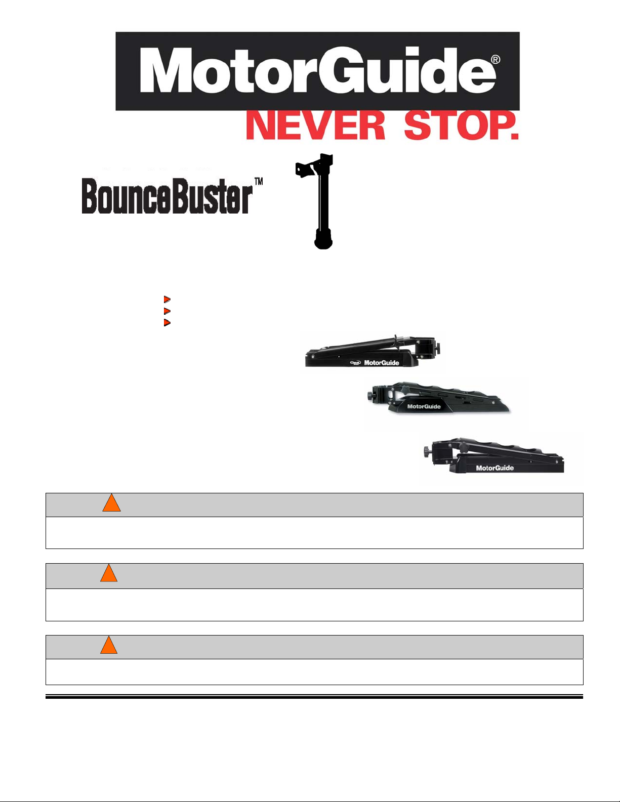
BounceBuster Original (MGA053B6)
Fits 20 and 23 Original Gator Mounts
BounceBuster II (MGA097B6)
Fits 21 and 24 Gator Spring Mounts
Bounce Buster III (MGB01102)
Fits 20.5 and 23.5 Gator Breakawa
Mounts
The BounceBuster Protects Stowed Trolling Motor, Mount, and Boat during high-speed o r ro ugh-water
running.
Designed for Tournaments and Rough Water Use
Minimizes Damaging G-Forces
Lengthens Life of Motor and Mount Protects Boat From Damage
BounceBuster Original (Gator 20/23 Mount)
Fits Gator Mount –MST920BF, MST920SW
BounceBuster II (Gator Spring/Spring XL Mount 21 and 24)
Fits Spring/Spring XL Mount –MST921BF, MST924BF
BounceBuster III (Gator Breakaway)
Fits Breakaway Mount MST920.5BF, MST923.5BF, MST920.5SW, MST923.5SW
DANGER:
Spring Tension must be relieved before servicing this mount. Failure to relieve the spring tension can result in severe
personal injury.
!
WARNING
DANGER:
To avoid arm assembly from springing upward, possibly causing personal injury, use one hand or have an assistant
apply downward pressure on top of the arm assembly when pulling the rope to unlock the bow arm.
!
WARNING
DANGER:
To avoid personal injury, keep your hands and fingers away from the area between the bow arm and deck channel.
!
WARNING
©2005, MotorGuide 90-MM6421
www.motorguide.com
Page 2
BUNCEBUSTER INSTALLATION INSTRUCTIONS
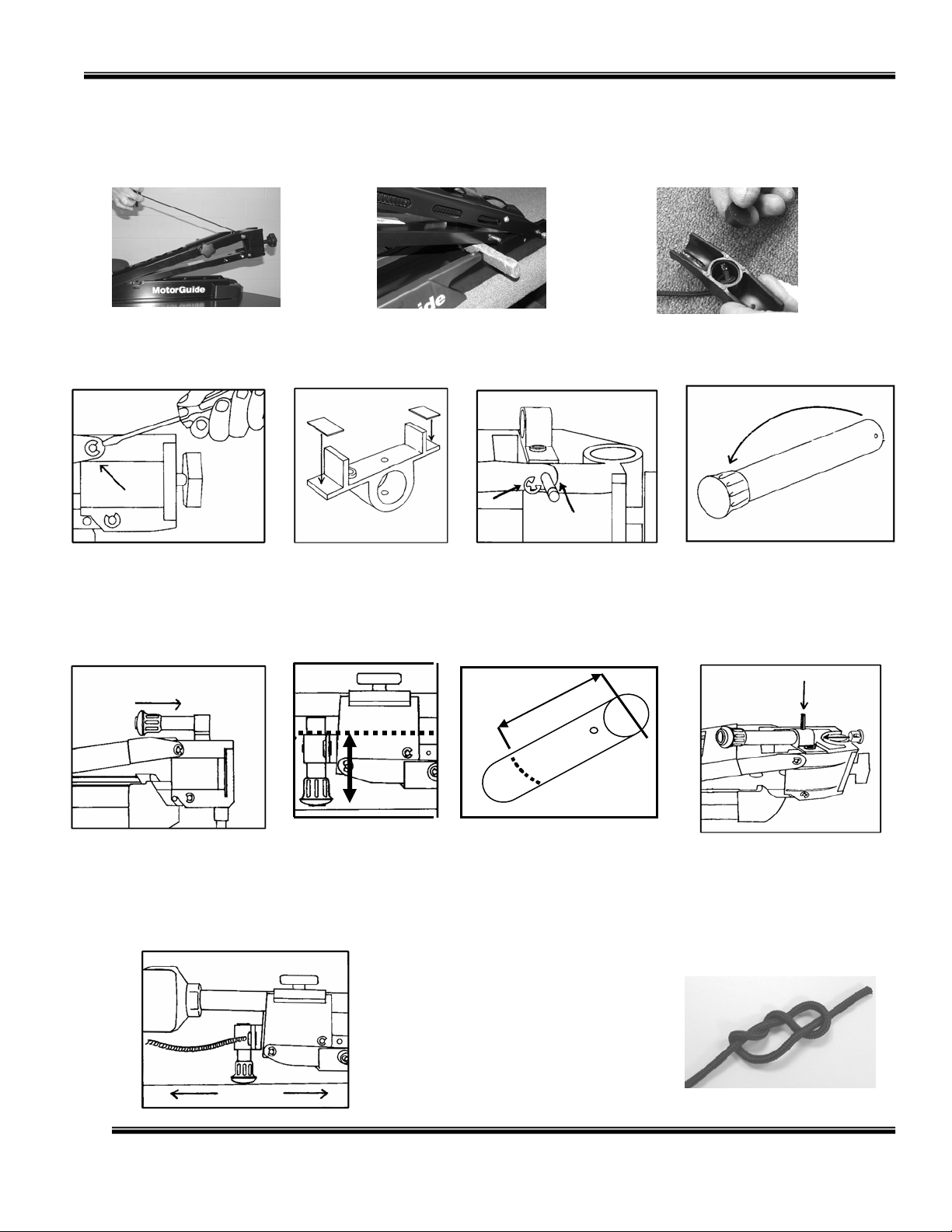
To prepare the mount for installing the BouncecBuster, pull the rope handle up to release the locking mechan ism. When the
bow arm is raised at an approximate 45 degree angle, place a block of wood between the bow arm and the deck channel.
(See photos below.) After the tension is relieved, the BounceBuster can be installed.
Raise Bow Arm to 4
Degree Angle
5
Insert a Block of Wood
between the Bow Arm
and the Deck Channel
Remove the plug in the handle.
Untie the knot in the rope. Slip
the rope out of the handle.
1) Remove the E-ring, spacer
washers and top pivot pin as
shown.
5) Slide the support tube into the
BounceBuster bracket with the
rubber end cap facing toward the
back of the boat.
2) Install the self-adhesive
pads on the underside of the
bracket ends.
A
B
6) With the mount in the
stow lock position, measure
the distance between the
boat deck (B) and the top of
the BounceBuster bracket
tube hole (A).
9) Route the rope end through the bushing in the
bracket and then route the rope through the hole in
the handle. Tie a Stevedor knot in the rope end and
then install the plug in the handle over the knot.
Test the BounceBuster by putting the mount back
in the stow position. The Mount should lie flat and
the stow lock pins should engage. If the mount
does not lie flat and the lock pins do not engage, an
additional cutting adjustment may be needed.
3) Position the BounceBuster
bracket so that the pads on the
underside are resting on the flat
surface of the Bracket door
assembly. The rope hole should
be placed toward the inside of the
boat. Reinstall the pivot pin,
washer spacers and E-ring.
A
B
7) Remove the support tube from
the bracket. Remove the padded
end cap from the tube. Using the
measurement from Step 6 plus ¼
inch, measure from tube end (A)
downward to point (B). Mark a cut
line and then cut the tube at the
mark.
4) Place the rubber end cap on the
end of the support tube without
holes.
8) Place the support tube
back into the BounceBuster
bracket aligning the holes on
the tube with the holes on
the bracket. Secure the
tube to the bracket with the
roll pin. Install the plug in
the tube end.
Stevedor Knot
©2005, MotorGuide 90-MM6421
www.motorguide.com
 Loading...