

Motor Guard Magna-Spot JO1000, Magna-Spot JO2000, Magna-Spot JO1500 Instruction Manual
INSTRUCTION MANUAL
Magna-Spot® Studwelder
Models JO1000, JO1500, JO2000
*
WARNING: Read and understand all instructions before attempting to operate tool.
Failure to follow instructions may result in electric shock, fire and/or serious personal injury.
IMPORTANT SAFETY INSTRUCTIONS
To reduce the risk of serious injury and/or property
damage, observe all warnings and instructions while
* 8
+ !
+
operating the welder. Keep work area clean and well lit.
Maintain tool in top condition and obtain service from
manufacturer if tool malfunctions. Use only accessories
and replacement parts that are provided by the
manufacturer.
To reduce the risk of electrical shock: Do not expose
welder to rain or wet conditions. Water entering tool will
increase the risk of electrical shock. Unplug welder when
not in use. Do not operate welder with any portion of the
housing removed. Disconnect welder from power supply
before servicing any part of the welder. Failure to follow
these instructions will increase the risk of electrical shock.
Do not abuse power cord. Never use the power cord for
carrying, pulling or unplugging the welder. Keep power
cord away from heat, sharp edges and moving parts.
Replace power cord immediately if it becomes damaged.
Damaged cords increase the risk of electrical shock.
O
A
This welder must be connected to a properly
grounded outlet installed in accordance with all local
codes and ordinances. Never remove the grounding
prong or modify the plug in any way. Do not use adapter
plugs. Consult an electrician if you are in any doubt as to
whether the plug is properly grounded. Avoid bodily
contact with grounded surfaces.
Do not operate tool in explosive atmospheres, such
as in the presence of flammable liquids, gases or dust.
Welders create sparks which may ignite dust or fumes.
Use in well ventilated areas only. Welders generate heat
which can ignite surrounding materials causing fires. Do
not use welder on body panels containing insulating
material which may be ignited by the heat.
Always wear proper personal protection when
operating welder. Proper eye protection is required to
reduce the risk of eye injury from sparks and molten
metal. Adequate gloves and clothing are required to
reduce the risk of burns. Allow parts to cool before
handling.
SAVE THESE INSTRUCTIONS
IF YOU HAVE ANY QUESTIONS ABOUT THE OPERATION OF PRODUCT CALL TOLL FREE
8:00 am to 5:00 pm - Pacific Time - Monday through Friday
800-227-2822
3
PREPARING TOOL FOR USE
Read and understand all warnings and instructions prior to use.
For 120V operation in the US and Canada, a three prong plug is provided. For units rated at 240V, a field supplied, approved plug must be installed by
the user. Consult an electrician for the proper connector. Supply circuit receptacle, conductors, fuses and circuit breakers must be capable of handling
a 15 ampere load. Welder should be the only device connected to the circuit being used.
An adequate power supply is required for proper welding operation. The welder is provided with a 9 foot power cord which should be suitable for most
work stations. If an extension cord is required, it must be a three wire grounded cord with a minimum of 12 AWG conductors. Cord must not exceed 10
feet in length. Reduced welding capacity will result from the use of undersized or long extension cords.
GENERAL WELDING PROCEDURE
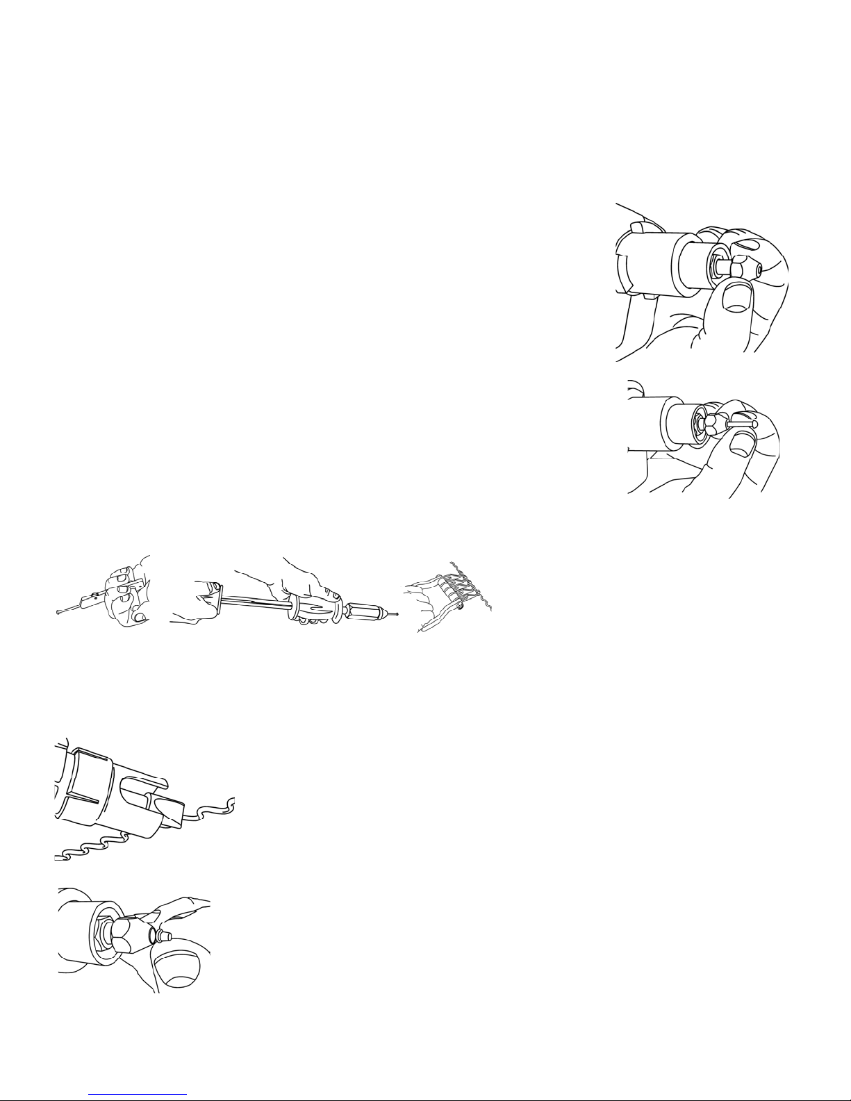
Select proper electrode tip for work to be performed. Insert electrode tip into welder, tapered end first, and
rotate slightly for a tight fit. (Fig. 1) Use opposite procedure to remove electrode tip. A box end wrench can be
used to twist electrode slightly to loosen.
Proper welding requires that the surface to be welded be clean, bare metal free of paint, primer, oil and dust.
Grind area to be welded to expose bright metal approximately one inch all around area to be welded.
Insert pin or rivet to be welded in electrode tip and place tip of electrode against exposed metal. Press until
outer electrode tube is in full contact with bare metal. Hold welder in this position and depress trigger for onehalf to one second. A proper weld is achieved when the heat affected area around the weld is approximately
1/4” in diameter. To prevent sparking, do not pull electrode tube back until trigger is released.
Figure 1
Do not hold trigger for more than one second as burn through may result. Operating the welder beyond its duty
cycle (one second on, 60 times per hour) will result in tripping of the circuit breaker. Allow welder to cool for one
minute before resetting the circuit breaker and resuming welding.
DENT REMOVAL WITH MAGNA-PINS®
Prepare metal at damaged area per above instructions. Insert Magna-Pin® electrode tip into welder followed by
a Magna-Pin
and heavier panels. Weld pin as instructed above.
Magna
panel thickness. (Fig. 3) Grip pins 1/2 inch from surface and apply steady pressure while working dent with
appropriate body hammer. Slide hammer action may be used for more extreme pulling.
Use side-cutting wire cutters to remove studs after repair. Rock pin and twist slightly until it breaks off.
®
. (Fig. 2) Use 2.0mm pins for dent removal on lightweight body panels and 2.5mm pins for posts
®
Slide Hammer, T-Puller or Clamp may be used for dent repair depending on extent of damage and
Rotate head of Slide Hammer clockwise 1/4 turn to grip
pins, opposite direction to release. Rotate knurled wheel
of T-Puller back to lock pin for pulling. To release, push
puller forward while rotating wheel forward. Electrode
Extension and Adapter Tube may be used for welding in
difficult areas and to place pins close together for more
Figure
®
Clamp
clockwise to tighten. Strike end of hook with
effective pulling with clamps. Rotate wing-nut on Magnahammer to release then loosen nut.
Figure 2
DENT REMOVAL WITH MAGNA-WIRE®
Prepare metal at damaged area per above instructions. Slide adapter over outer electrode tube. Tap into place as required to seat firmly. Insert Magna-
®
Wire
electrode tip into welder. Use 16 Ga. wire for dent removal on lightweight body panels and 12 Ga. wire on heaver panels. Place wire between
body panel and tip of electrode as shown. (Fig. 4) Weld as instructed above. Weld wire at each contact
point or at alternating points as required. Take care not to burn through wire by applying too much heat.
Use Magna-Claw
®
Claw
fingers provide self-leveling action by pulling deeper recesses first until dent is removed.
®
or other device to work crease out, starting at one end and working to the other. Magna-
Use pliers to remove wire by rocking back and forth at weld points.
TRIM RIVET INSTALLATION
Figure 4
Prepare metal at area of rivet installation per above instructions. Insert trim rivet electrode tip into welder
followed by trim rivet. (Fig. 5) Rivet will be held by magnet in electrode. Weld as instructed above.
SHRINKING STRESSED METAL
Shrinking electrode tip can be used to raise low areas or shrink high spots. Prepare area around damage as
instructed above. Insert shrinking electrode tip into welder.
To remove low spots, place rounded tip of electrode at several points around spot and depress trigger for onehalf second two or three times. Be sure outer electrode tube is in contact with bare metal while doing this.
Immediately apply cold blocking or wet cloth to area to shrink it back to its original shape.
Figure 5
33115
Rev 10/08 Page 2
To remove high spots and repair pin weld points, place rounded tip of electrode directly on high spot and
depress trigger for one-half second. Repeat as needed. A gentle hammer on heated metal may be used for
heavier damage.
 Loading...