

Motor Company Warehouse SDS30OC400V10, SDS15OC400V10, SDS45OC400V10, SDS22OC400V10, SDS185OC400V10 User Manual
...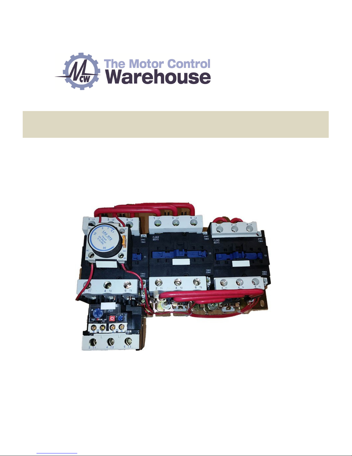
Open Chassis Star-Delta Starter User Guide
(7.5kW~9
0
kW)
V2
.
0.1

SDS Open Chassis Star-Delta Starter User Guide
Contents
1 Safety information ................................................................................ 1
2 Technical Data ...................................................................................... 2
3 Supply & Motor Connections & Circuit Diagrams ............................... 5
4 Control Connections & Operation ....................................................... 8
www.motorcontrolwarehouse.co.uk
Copyright © Motor Control Warehouse October 2017
Revision V2.0.0
Open Chassis Star-Delta Starter User Guide
P a g e | 1
1
Safety information
Safety Information
This chapter provides very important information so that you can use the SDS Open Chassis Star-Delta Starter
safely, prevent injury or death, or damage to equipment. Please read this information thoroughly and make
sure you observe all the safety information shown below and elsewhere in this manual. Please make this User
Guide available for the end user.
Safety symbols
• The SDS Open Chassis Star-Delta Starter should ONLY be installed, commissioned and maintained by
qualified and competent personnel.
• The OC SDS must be installed to the latest IEE wiring regulations taking into account local
regulations.
• Dangerous voltages are present when the input power supply is connected to the OC SDS. Before
attempting any work on the OC SDS or motor, isolate and lock off the input power supply. Prove
dead using a voltage tester. The voltage tester itself should be proved immediately before and after
testing using a proving unit with a low power output.
• The OC SDS backplate must be connected to system ground using the earth terminals. The size of
the earth conductor and earth loop impedance must comply with national and local electrical
regulations.
• The SDS is a non-field repairable unit. Contact the supplier of the SDS.
• The mains supply and control supply to the OC SDS must be protected by suitable rated
fuses/MCBs.
• All machinery, in which this OC SDS is used, within the European Union, must comply with directive
98/37/EC, Safety of Machinery.
• Do not install the OC SDS in an explosive environment.
• The motor must be used within the manufacturers guidelines.
• Do not allow conductive material to enter the components within the OC SDS, e.g. from drilling
during installation.
Danger of electrical shock which can cause injury or death, or damage to equipment
Danger
:
Warning:
Potential hazard, other than electrical, that can cause physical injury or damage to equipment
Danger
Warning
P a g e | 2
Open Chassis Star-Delta Starter User Guide
2
Technical Specification
Technical data
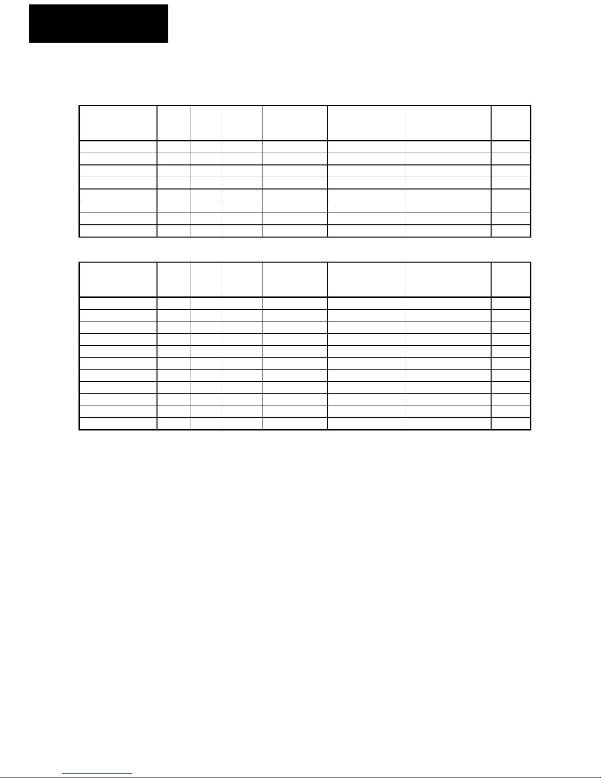
Trip Class 10
Model kW
rating
Input
phase
Input
voltage
(VAC)
Max allowed
motor current
(A)
Motor current (A)
(overload range)
Trip Class 10
Overload range
(A)
Typical
Motor
(A)
SDS075OC400V10 7.5 3 400 17 15.5 to 22 9 to 13 16
SDS11OC400V10 11 3 400 22 20 to 31 12 to 18 20
SDS15OC400V10 15 3 400 29 29 to 43 17 to 25 27
SDS185OC400V10 18.5 3 400 36 29 to 43 17 to 25 34
SDS22OC400V10 22 3 400 44 39.5 to 55 23 to 32 41
SDS30OC400V10 30 3 400 59 52 to 69 30 to 40 55
SDS37OC400V10 37 3 400 75 63 to 86 37 to 50 72
SDS45OC400V10 45 3 400 89 82 to 112 48 to 65 86
Trip Class 20
Model kW
rating
Input
phase
Input
voltage
(VAC)
Max allowed
motor current
(A)
Motor current (A)
(overload range)
Trip Class 20
Overload range
(A)
Typical
Motor
(A)
SDS075OC400V20 7.5 3 400 17 15.5 to 77 9 to 45 16
SDS11OC400V20 11 3 400 22 15.5 to 77 9 to 45 20
SDS15OC400V20 15 3 400 29 15.5 to 77 9 to 45 27
SDS185OC400V20 18.5 3 400 36 15.5 to 77 9 to 45 34
SDS22OC400V20 22 3 400 44 15.5 to 77 9 to 45 41
SDS30OC400V20 30 3 400 59 31 to 155 18 to 90 55
SDS37OC400V20 37 3 400 75 31 to 155 18 to 90 72
SDS45OC400V20 45 3 400 89 31 to 155 18 to 90 86
SDS55OC400V20 55 3 400 108 31 to 155 18 to 90 98
SDS75OC400V20 75 3 400 135 31 to 155 18 to 90 129
SDS90OC400V20 90 3 400 170 103 to 206 60 to 120 158
NOTE: The thermal overload setting is set to minimum as default. It should be adjusted to suit the motor
used.
To calculate the thermal overload setting = Actual motor nameplate current ÷ 1.7 x 1.1 (10% safety margin to
prevent spurious tripping).
NOTE: Due to the large range of the thermal overloads on the Trip Class 20 star delta starters, please make
sure the thermal overload is adjusted correctly to suit the motor.
NOTE: Starting the motor more than once every 10 minutes will alter the thermal overload tripping
characteristic by heating the current sensing elements, making the overload trip more quickly for a given
setting.
Open Chassis Star-Delta Starter User Guide
P a g e | 3
2
Technical Specification
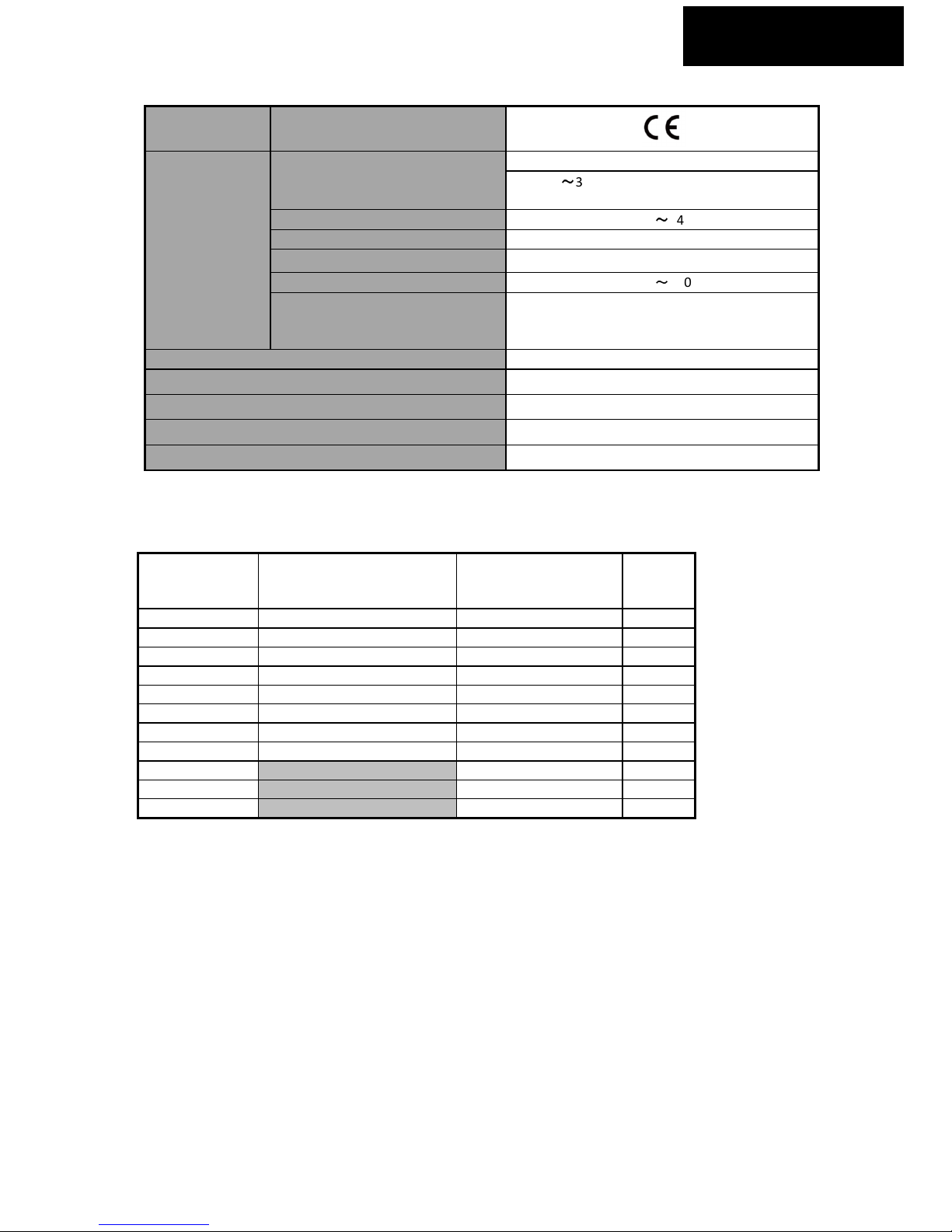
Approvals CE approval
Environment
Altitude
1000m rated
1000m~3000m, 1% rated current de-rating per
100m above 1000m
Operating Temperature
−10°C~+40°C
Max. Humidity ≤90%RH, non-condensing
Vibration ≤5.9m/s2 (0.6g)
Storage Temperature
−40°C~+70°C
Running Environment
Non-flammable, No corrosive gasses, no
contamination with electrically conductive
material
Supported Power Supply Systems TT & TN
OC SDS Enclosure IP20 (must be installed in an enclosure)
Supply frequency 50 to 60Hz
Supply voltage 3 phase 400VAC ±10%
*Contactor coil voltage 400VAC / 240VAC / 110VAC (+/-10%)
*Model dependant
OC SDS Dimensions
Model Dimensions
(H x W x D)
Trip Class 10
Dimensions
(H x W x D)
Trip Class 20
Approx.
Weight
(kg)
SDS075OC400V 170 x 180 x 170 170 x 180 x 170 2.2
SDS11OC400V 170 x 180 x 170 170 x 180 x 170 2.2
SDS15OC400V 200 x 300 x 190 200 x 300 x 190 5
SDS185OC400V 200 x 300 x 190 200 x 300 x 190 5
SDS22OC400V 200 x 300 x 190 200 x 200 x 200 5
SDS30OC400V 200 x 320 x 200 200 x 320 x 200 5
SDS37OC400V 200 x 320 x 200 200 x 320 x 200 5
SDS45OC400V 200 x 320 x 200 200 x 320 x 200 5
SDS55OC400V 200 x 320 x 200 5
SDS75OC400V 350 x 480 x 150 10
SDS90OC400V 350 x 480 x 150 10
NOTE: The above dimensions are only approximate and do not take into account the size of the thermal
overload on the trip class 20 star delta starters.
NOTE: The contactor sets between the Trip Class 10 and Trip Class 20 open chassis star delta starter may differ
hence the physical size of the trip class 20 may be larger than the equivalent trip class 10 model.
NOTE: The open chassis star delta starters are supplied pre-wired on a back plate. The starting and stopping
method will need wiring into the star delta starter. See Control Connections & Operation section of this User
Guide for example connections.
NOTE: The thermal overload is fitted into the output of the main contactor on the Trip Class 10 product. The
Trip Class 20 thermal overload is supplied as a separate module which will need to be mounted separately
from the contactors and wired into the output of the main contactor.
 Loading...