

Page 1

Dashboard
/ …
/ motorBench 2.25 Release
Created by Fernando Garibaldi, last modified by Jason Sachs 4 minutes ago
motorBench User's Guide
Introduction
Recommended Reading
Hardware Setup
MCLV-2
MCHV-2 and MCHV-3
Sample motorBench Projects
Operating Instructions
Getting started
Configuration
Motor Import and Export
Importing a motor
Exporting a motor
Motor parameter measurement
Common types of motor parameter measurement errors and reasons they can occur
Autotuning
Managing Errors in Autotuning
How to identify autotuning errors
Common types of autotuning errors and reasons they can occur
How to report specific failure details to Microchip for assistance
Customize
Position and velocity estimator selection
Advanced parameters
Normalized parameters
Advice
Additional information
Generate Code
Managing Errors in Code Generation
How to identify code generation errors
Common types of code generation errors and reasons they can occur
How to report specific failure details to Microchip for assistance
Building Code
Running the Application Framework
MCLV-2
MCHV-2 and MCHV-3
Real-Time Diagnostics
Troubleshooting Issues with some motors
Appendix
Motor parameter measurement - Calibration load specifications
Introduction
This document describes how to setup hardware, configure, and operate motorBench® Development Suite as well as aid in troubleshooting issues with motors. For information on
installing motorBench please refer to the motorBench Release Notes. This document does not advise how to use the resulting generated code. Please refer to the MCAF User's Guide for
additional information.
Recommended Reading
This user's guide refers to motorBench operation only. Other useful documents are listed below:
MPLAB® Code Configurator v3.xx User's Guide
MCAF User's Guide
Hardware Setup
The following sections outline the hardware setup of MCLV-2, MCHV-2, and MCHV-3.
MCLV-2
Hardware setup: MCLV-2
This section provides detailed steps that will help you setup your hardware to work with the motorBench® Development Suite:
1. MCLV-2 board comes pre-installed out of the box with dsPIC33EP256MC506 Internal Op Amp Motor Control PIM (MA330031); replace this PIM with
the dsPIC33EP256MC506 External Op Amp PIM (MA330031-2) or dsPIC33CK256MP508 External Op Amp PIM (MA330041-1) specified above.
2. Make sure that the dsPIC33EP256MC506 External Op Amp PIM is populated with a silicon mask rev-A8 or later. To verify this, read out the device revision from MPLAB X and
verify that the Device ID revision is equal to or greater than 0x4008.
Page 2
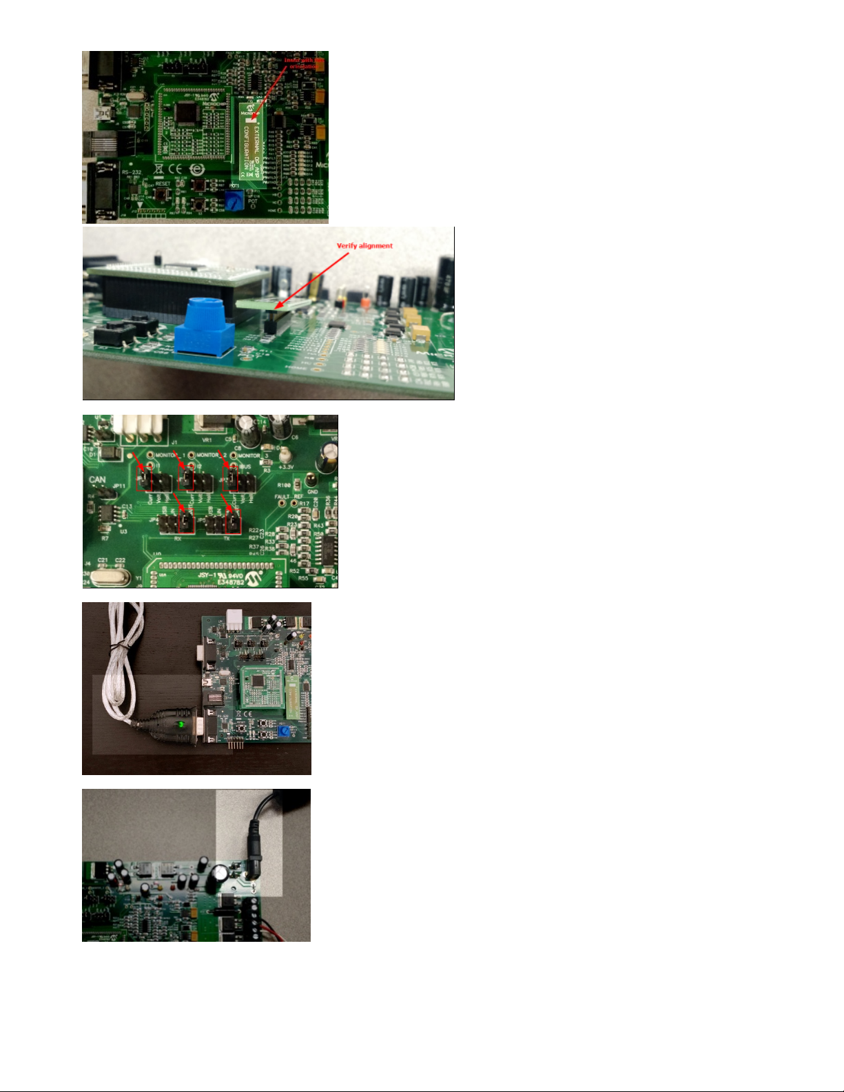
3. Install the External Op Amp Configuration matrix board that comes with the MCLV-2 board into J14
4. Update the jumpers JP1-JP2-JP3 to Curr position and JP4-JP5 to UART position as shown below:
5. Connect the USB-to-logic-level-UART converter cable into J10 of MCLV-2 board and one of the USB ports on your PC:
6. Plug in the 24V power supply barrel connector into J2 of MCLV-2 board and then plug in the power supply into the mains outlet:
7. Connect your Real ICE / ICD3 / PICkit3 to one of the USB ports on your PC
Page 3
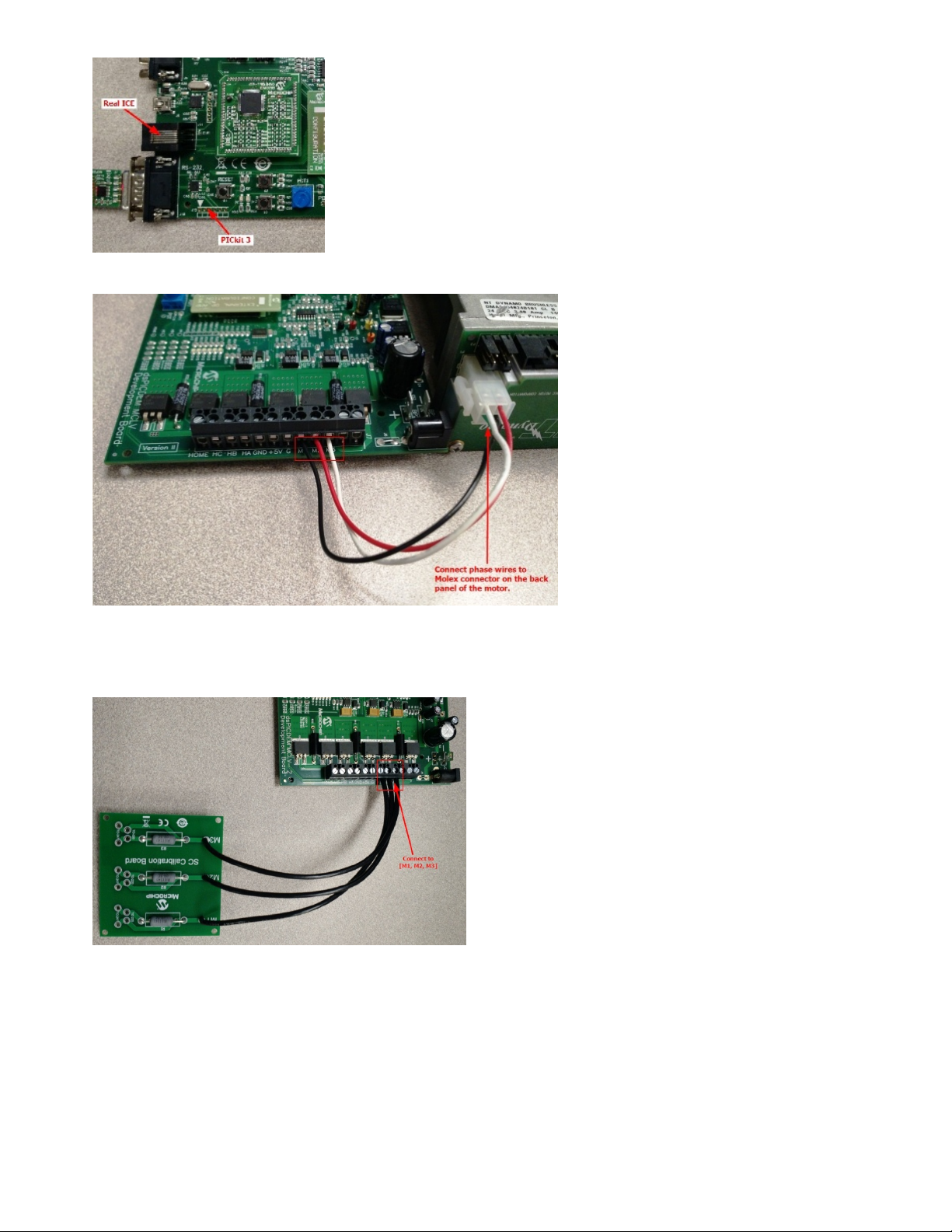
8. Connect the Real ICE / ICD3 to J11 of MCLV-2 board. If you are using PICkit 3, then connect it to J12 of this board.
9. Connect the [black, red, white] phase wires of the 24V BLDC motor to [M1, M2, M3] terminals of J7 connector on the MCLV-2 board. (Sequence / order of this
connection is not important if the direction of rotation does not matter.) You may leave the green color phase wire unconnected or connect it to the G terminal of J7 connector on
the MCLV-2 board. Then, plug in the other end with a Molex connector to the 24V BLDC motor.
10. Keep the motor on a stable surface and use a clamp (if available) to secure the motor from jumping around. (If using a metal C-clamp, make sure there is a thin shim of rubber,
cloth, wood, or other mechanically-compliant material between the clamp and the motor, to avoid deforming the motor housing.) Alternatively, you can also place the motor on a
rubber mat. Also, do not disturb the motor or hold its shaft while motor parameter measurement is running.
11. While running the Board Calibration within motor parameter measurement feature in motorBench® Development Suite, you will need to use a calibration load of three
equal-value resistors connected in place of the 24V BLDC motor. Please refer to the Appendix section of this document for more information on the calibration load. Once you
have the calibration load on hand, you can start by stripping off the insulation on the wires coming from the M1, M2 and M3 terminals of the Calibration load. Then connect
these wires into M1, M2, M3 terminals of the J7 connector on the MCLV-2 board.
MCHV-2 and MCHV-3
Hardware setup: MCHV-2 and MCHV-3
Hardware setup: MCHV-2 and MCHV-3
This section provides detailed steps that will help you setup your hardware to work with the motorBench® Development Suite: Although the setup is similar for MCHV-2 or MCHV-3,
pictures of MCHV-3 are shown in the below section
1. MCHV-3 board comes pre-installed out of the box with dsPIC33EP256MC506 Internal OpAmp Motor Control PIM (MA330031); replace this PIM with
the dsPIC33EP256MC506 External OpAmp PIM (MA330031-2) or dsPIC33CK256MP508 External OpAmp PIM (MA330041-1) specified above.
2. Make sure that the dsPIC33EP256MC506 External OpAmp PIM is populated with a silicon mask rev-A8 or later. To verify the revision of silicon, read out the device revision
from MPLAB X and make sure that the Device ID revision is equal to or greater than 0x4008.
Page 4
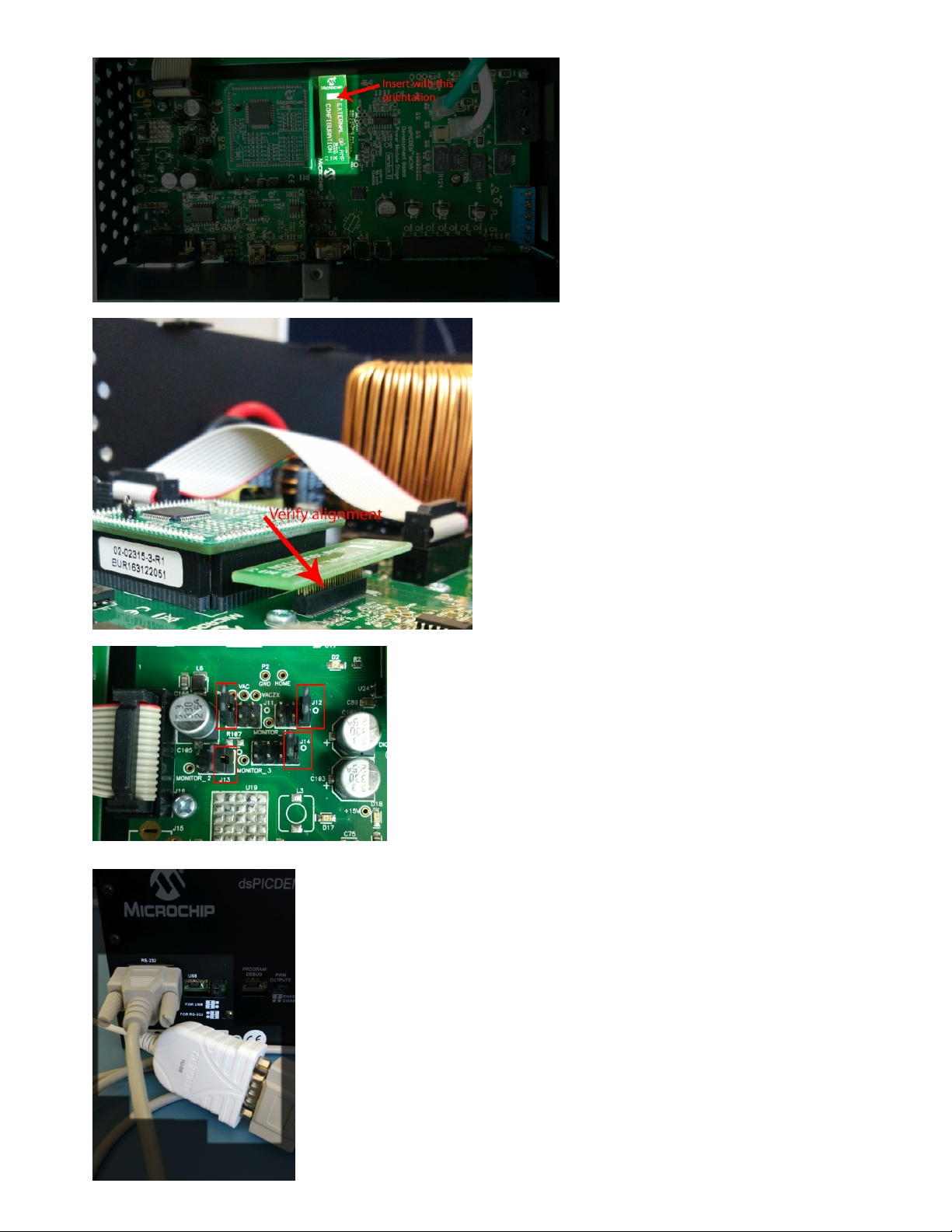
3. Install the External OpAmp Configuration matrix board that comes with the MCHV-3 board into J4
4. Update the jumpers J12-J13-J14 to 1-2 position and J11 to 5-6 position as shown below:
5. Connect the USB-to-UART converter cable into RS232 labeled port on MCHV-3 board and one of the USB ports on your PC:
Please note that in the event of mechanical interference with the USB-to-UART cable, you may need to use an UART extension cable.
Page 5
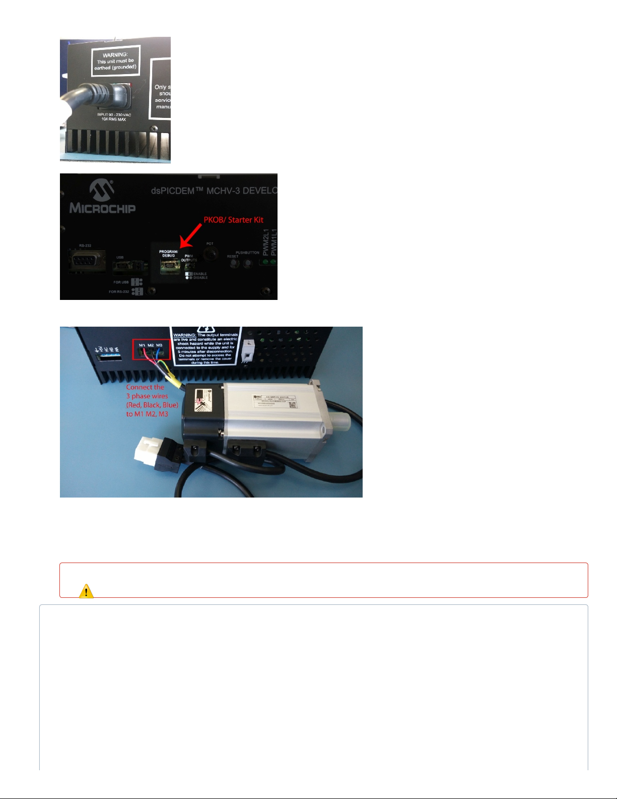
6. Plug in an appropriate ac power supply cable to MCHV-3 board and then plug in the AC power supply cable into the mains outlet:
7. Connect the provided USB cable to PROGRAM/DEBUG connector on MCHV-3 board and to one of the USB ports on your PC.
8. Connect the [red, black, blue] phase wires of the Leadshine 400W 220VAC Servo Motor (AC300025) to the [M1, M2, M3] terminals on the MCHV-3 board. (Sequence /
order of this connection is not important if the direction of rotation does not matter.) Connect the green-yellow combination color wire to the Ground terminal provided on the
MCHV-3 board.
9. Keep the motor on a stable surface and use a clamp (if available) to secure the motor from jumping around. (If using a metal C-clamp, make sure there is a thin shim of rubber,
cloth, wood, or other mechanically-compliant material between the clamp and the motor, to avoid deforming the motor housing.) Alternatively, you can also place the motor on a
rubber mat. Also, do not disturb the motor or hold its shaft while motor parameter measurement is running.
10. While running the Board Calibration within motor parameter measurement feature in motorBench® Development Suite, you will need to use a calibration load of three
equal-value resistors connected in place of the BLDC motor. Please refer to the Appendix section of this document for more information on the calibration load. Once you have
the calibration load on hand, you can start by stripping off the insulation on the wires coming from the M1, M2 and M3 terminals of the Calibration load. Then connect these wires
into the M1, M2, M3 terminals of connector on the MCHV-3 board.
Hazard warning
Whenever connecting or disconnecting a motor or calibration load from MCHV-2/ MCHV-3 board, please disconnect the power from the MCHV-2/ MCHV-3 board. Also,
use an insulated screwdriver that is recommended for high voltage rating.
There is a known hardware design limitation with MCHV-2 and MCHV-3 boards that can cause the device on a dsPIC33EP256MC506 External Op Amp Motor Control PIM to
reset when running motors with large phase currents. This issue does not affect dsPIC33CK256MP508. If you are observing dsPIC device reset issues while using MCHV-2 or
MCHV-3 board with this PIM and with certain test motors, power down the board, unplug the AC power cable, wait until LED D13 is OFF and then make the following
modification:
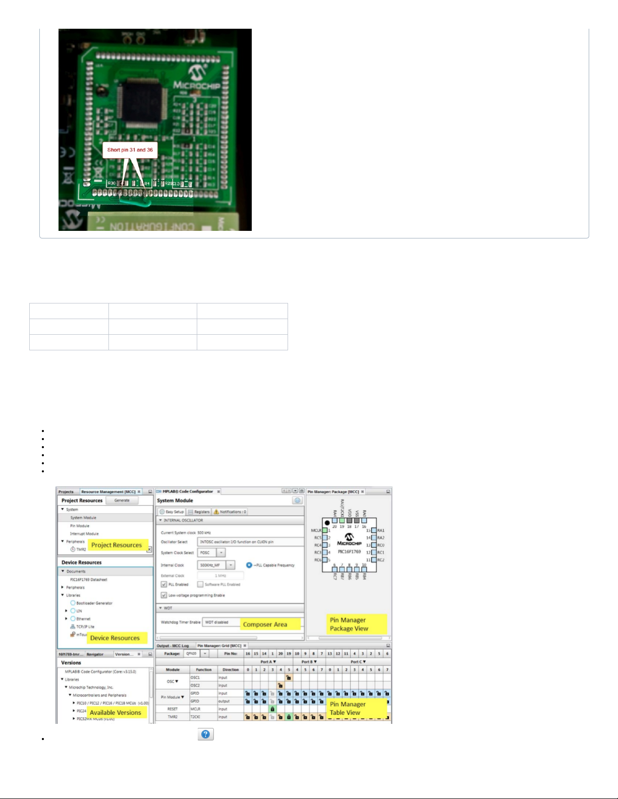
Use a short length of jumper wire to connect digital ground signal to analog ground signal on the PIM. To do this, connect pins 31 and 36 on the dsPIC33EP256MC506
External Op Amp Motor Control PIM:
Page 6
Sample motorBench Projects
motorBench® Development Suite requires all peripheral and system settings to be setup in MCC. The sample motorBench projects setup all peripheral, system, compiler, and linker
settings. To get started quickly please navigate to the motorBench website and choose one of the below projects based on your device, and board. To set up MCC manually refer to
the Peripheral Configuration Guide.
MCLV-2 MCHV-2/3
dsPIC33EP256MC506 sample-mb-33ep-mclv2.X sample-mb-33ep-mchv2.X
dsPIC33CK256MP508 sample-mb-33ck-mclv2.X sample-mb-33ck-mchv2.X
Operating Instructions
Getting started
Please start with any of the sample MPLAB X projects – the compiler, linker, and MCC System and Peripheral settings have been preset for use with the Motor Control Application
Framework.
Unzip one of the sample motorBench projects onto your computer
Open the sample motorBench project in MPLAB X
Right-click and set as the main project in MPLAB X
Right-click and open project properties. Select an in-circuit programmer (we have successfully tested ICD3 and REAL ICE) and XC16 compiler.
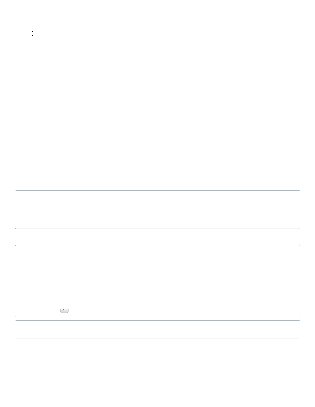
The MCC tool, once installed, can be launched from the MPLAB® X Tools menu under the Embedded selection, or by Clicking on the MCC icon in MPLAB X Toolbar.
The sections of the MCC tool are shown in the image below. We will refer to these sections by name throughout this guide.
The MCC help can be invoked by clicking on the
Page 7
Configuration
1. Select motorBench® Development Suite in Project Resources under Libraries.
The sample projects already have the motorBench library added.
If the motorBench library is not present in Project Resources (for example, starting from a new MCC project), you will first have to add it by locating it in Device Resources
under Libraries, and double-clicking on it.
2. If you haven't registered, you will be given the option to register motorBench, or enter a 30 day trial period. You will not be able to use motorBench after 30 days. For registration
steps on an offline machine please contact [email protected]
3. motorBench® Development Suite has three separate views
a. Composer view : This allows users to define and measure the system characteristics, tune the system characteristics and customize MCAF generation parameters. In
composer view, the user can
i. Configure the system: Allows user to configure the motor, board and estimator details. Users have the option to measure the electrical and mechanical parameters.
Users can export new motors.
ii. Tune the system: Once a motor has been imported, you can tune the system.
iii. Customize the MCAF parameters: Allows users to customize MCAF parameters that are used in code generation.
b. Pin Manager View: This allows users to see the various pins that are being used by the system.
c. Summary View: This allows users to see the various settings that are made by the user in the system.
4. Once you register, the "Home" page of the Composer view would show "Registered", otherwise it would show "Not yet Registered"
5. You can navigate between the “Configure”, “Tune” and “Customize” stages using their respective buttons.
6. Once all the components fully defined and there are no configuration errors, a puzzle icon will appear with status as "Ready to Generate". If the puzzle icon doesn’t appear
complete, check if there are any messages present in the “Notifications[MCC]” tab below that prevent completion, and resolve them.
Motor Import and Export
Each motor has a different characteristics, motorBench® Development Suite ships with two standard motor definitions: Hurst300 and Leadshine400.
You can Import either of these motors and modify if needed for the specific motor. Once modified you can export the changes as a different motor and use that later or share it with others
if needed.
The process of selecting a standard motor shipped with motorBench® Development Suite or created using export is called Import. Modifying and persisting it called Export.
Importing a motor
When the project is started for the first time, there would be no motor selected. Users have to click on the Import Motor button to select one of the exported motors or one of the
motorBench® Development Suite standard motors.
Begin by importing an existing motor. Clicking the 'Import Motor' button automatically takes you to the location on your machine where the default motors are stored.
Select your desired motor, and click 'Open'. The motor will be imported into motorBench® Development Suite.
motorBench® Development Suite is now ready to generate code. If you don't have any modifications to make to the project, you can generate code.
Exporting a motor
Once you have imported an existing motor, you may choose to change its parameter values.
All the motor parameters currently displayed in the composer view are editable, except the 'Measured Values' column in the 'Electrical and Mechanical Parameters' section. 'Measured
Values' are automatically calculated by the motor parameter measurement process discussed separately.
All numeric values are shown in Engineering Notation, but if you hover over them, you will be able to see their exact 'double' representations. This is the value that you will be editing.
Currently, we only support entering motor values in the units shown by default beside each parameter.
If you want to save the changes that you made to the motor parameters, you have two choices -
1. If you exit MCC, MPLAB X, or close the project, you will be asked whether you want to save the current MCC configuration. If you click 'Yes', all the changes will be preserved for
this project. The next time you open MCC for this project, you will find all your values intact. This will not export the motor file.
2. If you want to use your motor parameters for other/new projects, you can choose to export the motor. Clicking the 'Export Motor' button will bring up a dialog box that will allow you
to create your own motor with a new name. In a different project, you may choose to import this file instead of the default files provided with this installation.
Motor parameter measurement
After importing a motor, click on the "Measure Now" button in the Motor's Electrical and Mechanical Parameters group to open up the motor parameter measurement window.
1. Before you begin measurement, make sure that you have selected an ICD tool and a compiler.
2. Select the appropriate COM port from the combo-box. If you are unsure of the right COM port, you can look under the ‘Ports (COM & LPT)’ list in the Device Manager on
Windows, or type “ls /dev/*” on Mac. If you connected the board and ICD tool after you landed on the Measure page, you would want to hit ‘Refresh’ to update the list of COM
ports.
3. Acknowledge the heat-warning. You will not be able to proceed without it.
Location of default motors on Windows
C:\Users\<username>\.mcc\libraries\<versioned motorBench® Development Suite folder>\motors
Motor and your project
Note that once you import a motor into motorBench® Development Suite, there is no link between your project, and the file from which it was imported. You can see the file from
which the motor was imported in the 'Output - MPLAB® Code Configurator' window, but any changes you make are local to your project and do not affect the file.
Note that only the 'Active Values' in the 'Electrical and Mechanical Parameters' section are exported. 'Measured Values' cannot be exported. Measured values will, however, be
preserved for that specific project. If you have measured values generated by the motor parameter measurement process, you may choose to copy them to the 'Active Values'
column by clicking the or 'Use all' buttons.
Editing exported files
We do not recommend manually editing exported files. Using the UI to export motors is the best way of making any changes to the parameters you desire. If you still do edit the
file manually, there is a possibility that importing that motor into a project might fail without any warning or notification.
Page 8
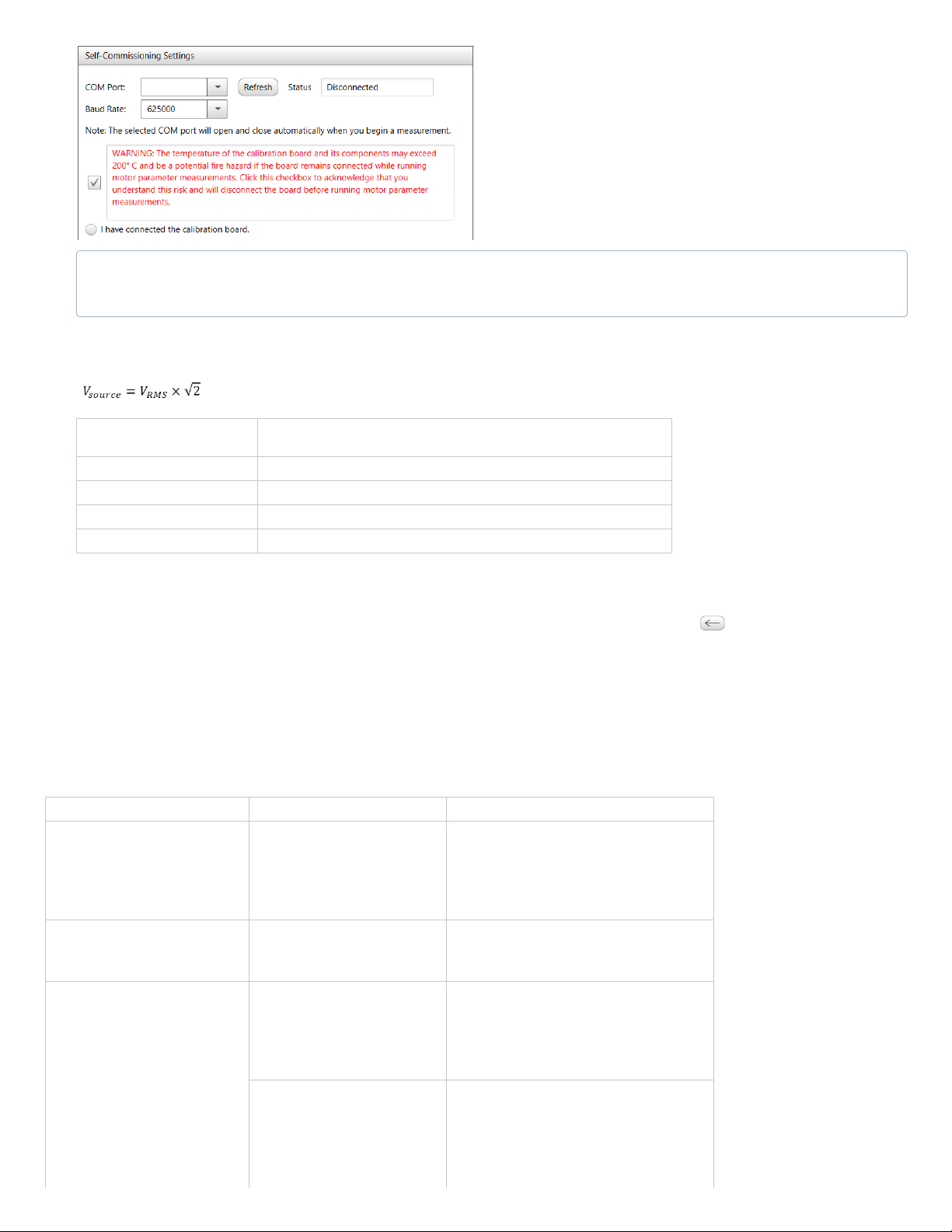
4. Verify that the Calibration Bus Voltage is correctly set for your hardware setup. This step is necessary even if you are planning on skipping the Calibration process. To
update this value, edit the value in Configure → Board → Voltage Source → Output. For the dsPICDEM MCHV-2 and MCHV-3 Development boards, this value can be
estimated from the nominal value of AC input voltage using the following equation or the table below:
Nominal AC input voltage
(V
RMS
)
Value to be entered in Configure → Board → Voltage Source → Output =
V
source
110 155.5
120 169.7
220 311.1
240 339.4
5. To calibrate, connect a valid calibration load (see Appendix for recommendations) and click the “I have connected the calibration board” radio button. Hit “Calibrate”.
6. To run the motor parameter measurements,
a. Disconnect the calibration load and connect the motor instead.
b. Click the “I have disconnected the calibration board” and “I have connected the motor” buttons.
c. Click the “Start” button to begin measurement. You will see the measured values appear for each parameter.
7. The measured values are updated in the 'Measured Values' of the Motor's Electrical and Mechanical Parameters section. Click on the icon to set a measured value as the
active value. The 'Use all' button can be used to set all measured values as active values. The 'Active Values' are used for Autotuning and code generation.
Common types of motor parameter measurement errors and reasons they can occur
General guidance: The usual cause of errors during motor parameter measurement is due to incorrect definition of motor and/or board specifications in the "Configure" page, specifically
these parameters:
1. Configure → PMSM Motor → Rated current: Continuous
2. Configure → PMSM Motor → Number of pole pairs
3. Configure → PMSM Motor → Nominal speed
4. Configure → Board → Voltage Source → Output
Table below provides some more specific examples of typical issues and their possible causes.
Symptom Possible causes Possible fix
Hardware over-current fault during R,
Ld or Lq measurements (Fault Code
#10)
Rated current specification of the
motor is close to / higher than the full
scale current range of the board. In
this case, with motors that have
relatively low values of electrical time
constant, current ripple can trigger the
over-current comparator on the board.
Retry the measurement after reducing the value in
Configure → PMSM Motor → Rated current:
Continuous to a lower value.
Motor stalls during inertia measurement
with a Fault Code #107
The specified Nominal speed of the
motor is either too low or too high for
the given voltage source output at the
inverter.
Correct the value in Configure → PMSM Motor →
Nominal speed and retry the measurement.
Motor stalls during Ke measurement
with a Fault Code #10, #102, #103,
#104, #105 or #106
If the test motor has a relatively low
value of stator inductance (typical Ld
and Lq ~ 100μH or less), then
transients in the current ripple can
trigger the hardware over-current fault
comparator causing the motor to stall
during startup.
Increase the Measure → Motor Parameters →
Current Controller → Phase Margin (slider) from its
default value of 95° in 5° increments up to a
maximum value of 115° and retry the measurement.
If the test motor has a relatively high
value of stator inductance (typical Ld
and Lq ~ 1mH or more), then the
current controller may need to be more
aggressive during the startup phase in
order to be able to suppress any open
loop oscillations that may cause
Decrease the Measure → Motor Parameters →
Current Controller → Phase Margin (slider) from its
default value of 95° to 91° and retry the
measurement.
The default communication baud rate setting during motor parameter measurement measurement is 625000. However, the RS232 transceiver devices used in MCLV-2 and
MCHV-2 development boards (i.e. MAX3232CUE) are specified to operate reliably at baud rates up to 120kbps. Due to this limitation, while using MCLV-2 development
board, MCHV-2 development board or MCHV-3 development board during motor parameter measurement, if you observe serial communication related issues, then retry
measurement after reducing the communication baud rate to a lower setting.
Page 9
disturbances in the current control
loop.
If the test motor has significant inertia
(typical J ~ 100μNm/(rad/s2) or more)
then, Measure → Motor Parameters
→ Approx. Spin Down Time
parameter may be set to value that is
too low for the given motor.
Increase the value that is set in Measure → Motor
Parameters → Approx. Spin Down Time and retry
the measurement. This will allow the measurement
algorithm to wait for the motor to spin down
completely before attempting to restart the motor in
between measurements.
Measurement fails during R
measurement with a message "Unable
to detect a motor on the board inverter
output. Please verify that the leads of
the motor under test are connected
securely to the board inverter output
terminals."
All three phase wires of the test motor
are not correctly connected to the
inverter output terminals.
Verify that all three phase wires of the motor are
connected correctly to the inverter output terminals.
Test motor has a stator inductance
value that is out of supported
measurement range.
-
Voltage source that is connected to the
inverter stage is not powered on.
Verify if the inverter stage is connected to a voltage
source that is powered on.
Autotuning
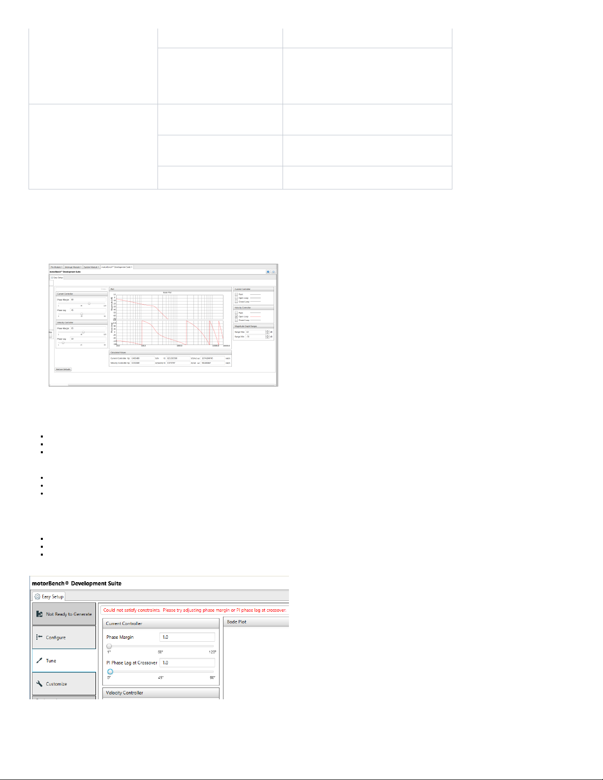
1. Click the ‘Tune’ button to go to the Tuning stage. There is no required user action in this stage. You can check out the Bode plots, or use different settings for phase margin or PI
phase lag at crossover, if you wish to do so.
2. We recommend the defaults of 80/45 and 65/10 for current and velocity controllers, respectively.
Motor parameters are extreme values, either because the motor parameter measurement process did not work correctly, or because the motor itself is unusual
Tuning parameters (phase margin and PI phase lag at crossover) are extreme values
Customize page parameters are extreme values
Important things to know are
How to recognize that an error has occurred
Common types of autotuning errors and reasons they can occur
How to report specific failure details to Microchip for assistance
How to identify autotuning errors
If an error has occurred during autotuning, the following will occur:
motorBench will show "Not Ready to Generate"
the Tune page will display a short status message in red, and no Bode plot will be drawn on the graphs
(in most cases) the Notifications [MCC] tab will show a list of problems
Managing Errors in Autotuning
Autotuning may fail in certain extreme cases:
Page 10
Common types of autotuning errors and reasons they can occur
Symptom Possible cause Possible fix
Tune page: "No motor imported" A motor has not been imported on the Configure
page.
Import a motor on the Configure page.
Tune page: "Could not satisfy constraints. Please try
adjusting phase margin or PI phase lag at
crossover."
Tune page parameters (phase margin or PI phase
lag) may be unusually low or high
Change tuning parameters to be closer to their default values. (The
"Restore Defaults" button will set these values back to their defaults.)
Estimator parameters on the Customize page may
be unusually low or high
Change estimator parameters to be closer to their default values.
(Customizable estimator parameters are AN1292 PLL time constant
and bandwidth and Quadrature encoder tracking loop time constant —
all of which are shown only if the "Show advanced parameters"
checkbox is checked.)
Certain other parameters (minimum operating
velocity) on the Customize page may be unusually
low or high
Change parameters to be closer to their default values.
Tune page: "Could not evaluate transfer function." May occurs if minimum operating velocity is zero. Choose a minimum operating velocity greater than zero.
Other symptoms (for example, "Could not locate
transfer function logic" or "Could not construct
transfer function")
Please report to Microchip – these are unexpected errors.
How to report specific failure details to Microchip for assistance
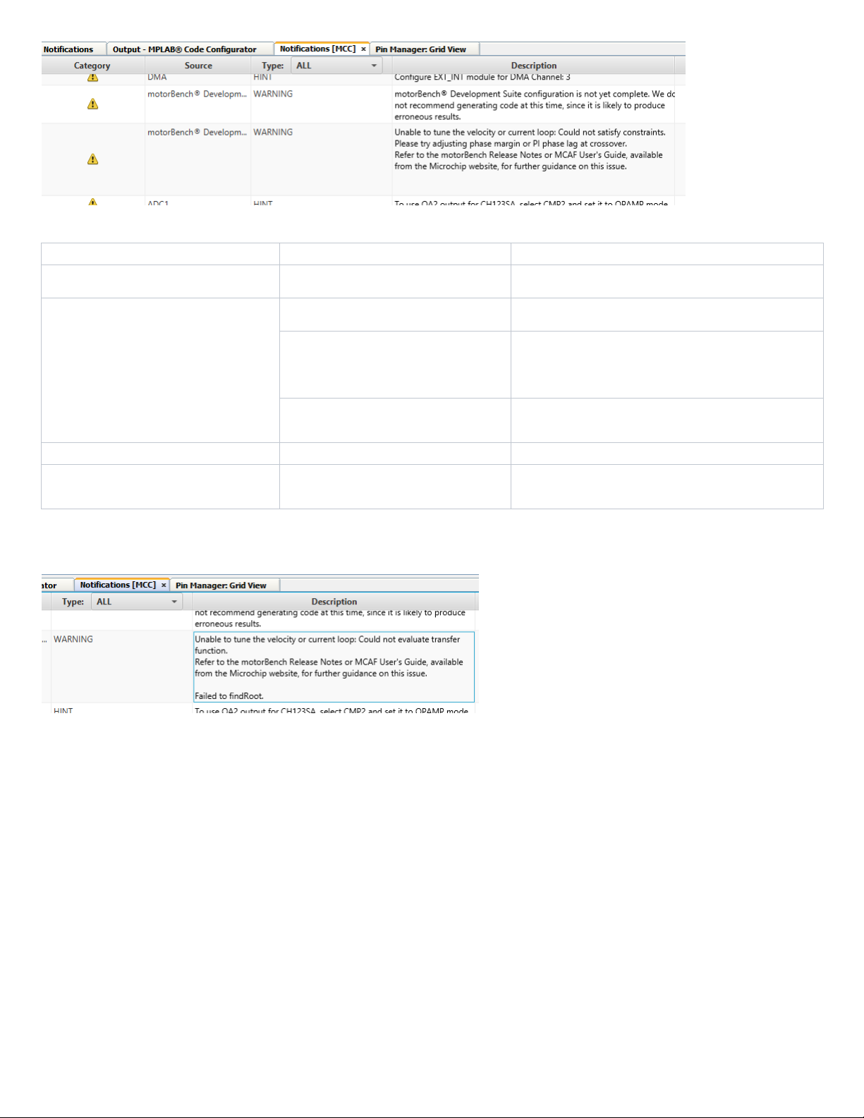
If contacting Microchip staff for assistance, please copy the entire text of the Tune page status message and the description of any MCC warnings – not just a screenshot. (Click on the
table cell in the MCC Notifications pane, so that it is highlighted as shown below, and press Ctrl+C to copy the text to the system clipboard.)
This provides important clues that may indicate the cause of the problem and how to address it.
Customize
The Customize page allows users to modify parameters used for MCAF code generation. This is an optional step to improve the behavior of the generated code for some motors; none of
the parameters on the Customize page need to be modified in order to generate code. The default values found in the Customize page are good for most motors.
Position and velocity estimator selection
Estimator selection is now made in the Customize page (in motorBench 2.15 and earlier, it was selected in the Configure page).
One estimator must be selected as the "primary" estimator used for commutation and velocity feedback. Additional estimators may be selected as secondary estimators for comparison of
angle and velocity information.
Refer to the MCAF User's Guide for more detailed information about the different position and velocity estimators.
Advanced parameters
There are several dozen customizable parameters, but most of these are considered "advanced" and are used only in rare cases to solve specific problems. Only a handful of parameters
are shown by default; to show all parameters, click on the checkbox marked "Show advanced parameters" at the top of the Customize page.
Normalized parameters
Many parameters are normalized to motor or system values, in order to ensure consistent default behavior. For example, the startup current Iq0 is specified as a fraction of maximum
current. The Customize page will display the actual value in real-world engineering units as a visual and computational aid.
Page 11
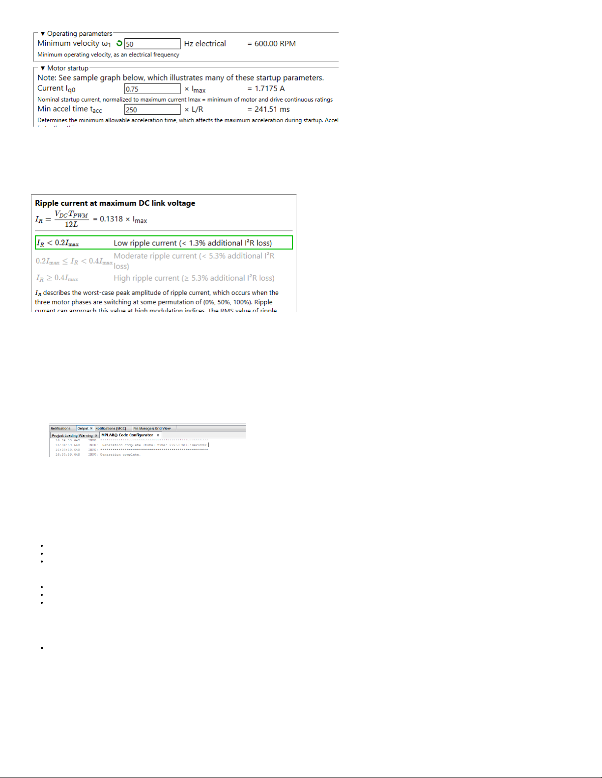
Each of these parameters has a default value. When editing parameters, if the value is different from the default, a green circular arrow will be displayed. Hover over the green circular
arrow to view the default value. To restore the value to its default, click on the green circular arrow.
Advice
An "Advice" section has been added to the Customize page to provide guidance on the effect of certain system quantities such as ripple current, as shown below:
This information is provided to highlight specific quantities that may cause problems in some systems. These are general guidelines and may not apply to all motor control systems.
Additional information
Refer to the MCAF User's Guide for more detailed guidance on parameter customization.
Generate Code
1. To generate code, click "Generate" under the Project Resources section. Look for the generation progress under the MPLAB® Code Configurator console window.
Once generation is complete, you will see a banner comment like so -
You will also be able to see the generated files added to your project.
2. If you want to run generation again, and have not made any manual edits, consider removing previously-generated files under the mcc_generated_files/motorBench directory. This
will avoid having to merge newly-generated files with earlier-generated files.
3. You are now ready to build and run the project, and spin the motor.
Managing Errors in Code Generation
Motor parameters are extreme values, either because the motor parameter measurement process did not work correctly, or because the motor itself is unusual
Tuning parameters (phase margin and PI phase lag at crossover) are extreme values
Customize page parameters are extreme values
Important things to know are
How to recognize that an error has occurred
How to report specific failure details to Microchip for assistance
Common types of code generation errors and reasons they can occur
How to identify code generation errors
If an error has occurred during code generation, the following will occur:
A dialog box will pop up with an error message:
Code generation may fail in certain extreme cases:
Page 12
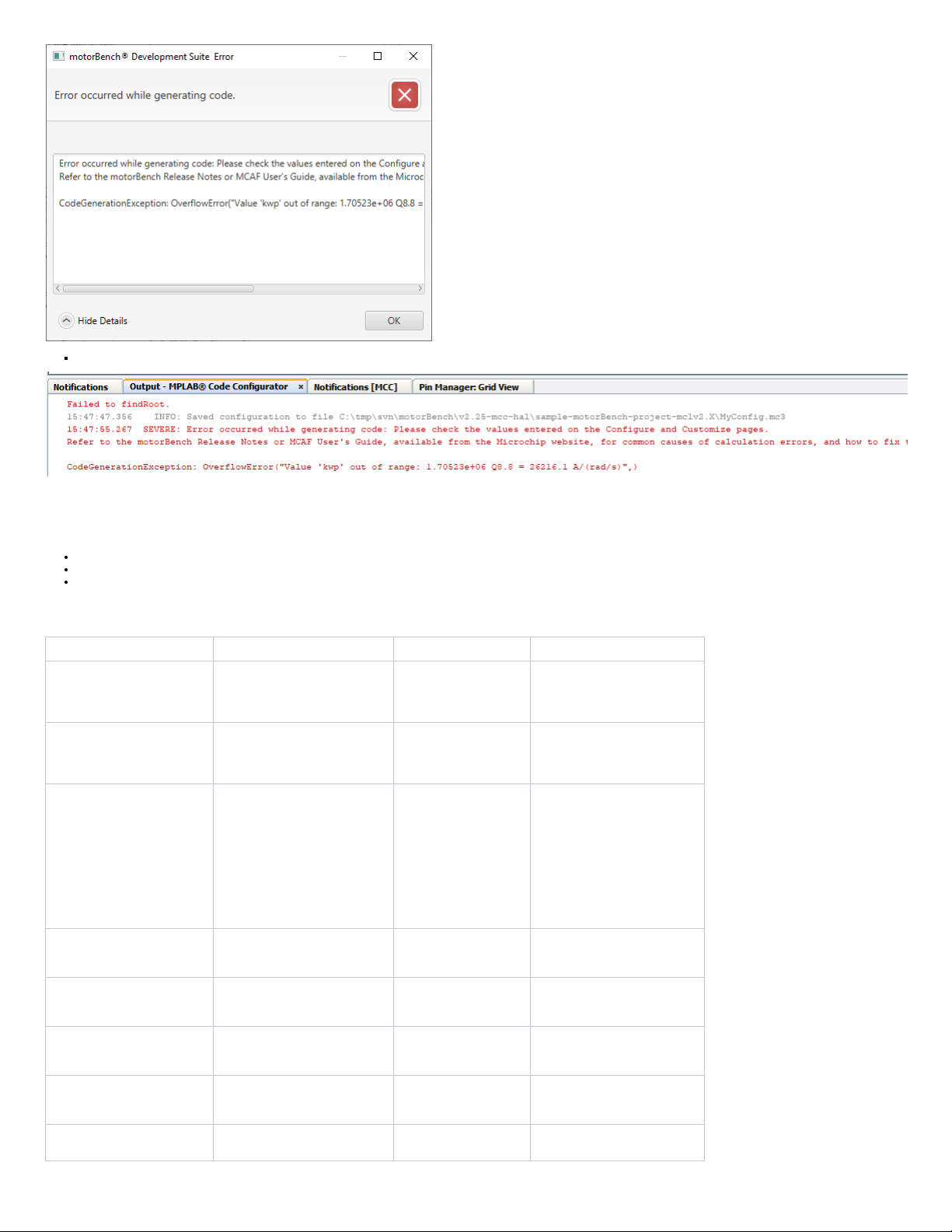
MPLAB® Code Configurator console window will have a SEVERE category message like shown below -
Common types of code generation errors and reasons they can occur
General guidance: The usual cause of code generation errors is a motor parameter that is extremely high or extremely low. Please see the section "Motor Control Limitations" which
discusses ranges of motor parameters that work well with motorBench® Development Suite. There are a few reasons a motor parameter could cause a code generation error:
The parameter has not been measured or entered correctly. (For example, a datasheet states 50µH but is entered as 50mH = 0.05H.)
The motor has unusual motor parameters. (Slotless motors may fall into this category; they have very low inductance.)
The motor is not well-matched to the motor drive circuitry, for example use of a 6V motor with a 24V motor drive.
The Customize page parameters may be at an extremely high or low value either.
Looking at the error message may help to diagnose and check for a fix.
Symptom: category Symptom: specific message Possible cause Possible fix
ZeroDivisionError One of the motor
parameters is zero. (This
should never be the
case.)
Make sure none of the motor
parameters are zero.
ZeroDivisionError One of the Customize
page parameters is zero
Check whether there are
Customize page parameters that
are zero, but should be greater
than zero.
CodeGenerationException:
OverflowError
kwp out of range This is the velocity loop
proportional gain. Out-ofrange errors can occur if
the inertia (J) is very high.
Make sure the inertia value is
reasonable.
An increase or decrease in
velocity loop phase margin in the
Autotuning page may be required
for high-inertia motors.
(Increasing phase margin
generally lowers kwp whereas
decreasing phase margin raises
it.)
CodeGenerationException:
OverflowError
velocitySlewrateLimitDecel
out of range
May occur if Coulomb
friction torque (Tfr) is out
of range.
Make sure the Coulomb friction
value is reasonable.
CodeGenerationException:
OverflowError
normLsdt out of range May occur if inductance
(Ld and/or Lq) is out of
range.
Make sure the motor inductance
values are reasonable and wellmatched to the motor drive.
CodeGenerationException:
OverflowError
normRs out of range May occur if resistance
(Rs) is out of range.
Make sure the motor resistance
values are reasonable and wellmatched to the motor drive.
CodeGenerationException:
OverflowError
(Other messages) A parameter on the
Customize page is at an
extreme value
Recheck values on the
Customize page.
Other errors Please report to Microchip –
these are unexpected errors.
Page 13
How to report specific failure details to Microchip for assistance
If contacting Microchip staff for assistance, please copy the entire text of the dialog box or MCC Output window — not just a screenshot.
This provides important clues that may indicate the cause of the problem and how to address it.
Building Code
At this point, work in motorBench® Development Suite is complete. In MPLAB X, click the Clean button and then the Run button to build and program the device.
Reminder: the Motor Control Application Framework requires certain compiler and linker settings; without these settings it may not run correctly. Please refer to the motorBench
Release Notes for compiler and linker settings.
Running the Application Framework
Directions for using MCAF with MCLV-2 and MCHV2/MCHV-3 are slightly different:
MCLV-2
Press button S2 to start/stop the motor
Press button S3 to reverse direction
Turn the potentiometer to control speed
In the event of an error, both LEDs (D2 and D17) will flash together to indicate an error code; see the Motor Control Application Framework documentation on the motorBench®
Development Suite webpage for further information.
MCHV-2 and MCHV-3
Press the button labeled PUSHBUTTON to start/stop the motor
Long press the button PUSHBUTTON (minimum 3 seconds) to reverse the direction of rotation.
Turn the potentiometer to vary speed.
In the event of an error, both LEDs (D17 and D19) will flash together to indicate an error code; see the Motor Control Application Framework documentation on the motorBench®
Development Suite webpage for further information.
Real-Time Diagnostics
The Motor Control Application Framework includes out-of-the-box support for X2C-Scope, a third-party plugin for MPLAB X which facilitates real-time diagnostics. X2C-Scope is available
in the same Available Plugins tab used to install motorBench® Development Suite.
Troubleshooting Issues with some motors
We have observed some issues during our testing under the following circumstances:
1. Starting up small motors with large inertia loads
2. Starting up certain motors with low speed reference
3. Instability in current loop
These are some solutions that may work for some motors:
1. Starting up small motors with large inertia loads using the classic startup method may have a difficult time with the transition from forced commutation to closed-loop commutation.
Use the Weathervane startup method in these circumstances.
2. Starting up certain motors with low speed reference fails to start. This may be due to either an issue in the startup method or the behavior of the sensorless estimator during the
transition to closed-loop commutation. Workarounds for this issue include: use the Weathervane startup method, ensure that the speed command is not at the low end of its range,
or reduce the DC link voltage if possible.
3. If instability in current loop is observed an increase of 5° or 10° in current loop phase margin may help.
Appendix
Motor parameter measurement - Calibration load specifications
The board calibration process analyses the hardware to measure any deviation from its design values of board parameters. This will help improve the accuracy of motor parameter
measurements. The board calibration step of motor parameter measurement is optional. However, it is recommended that at the least, it is run once every time there is a change in the
development board.
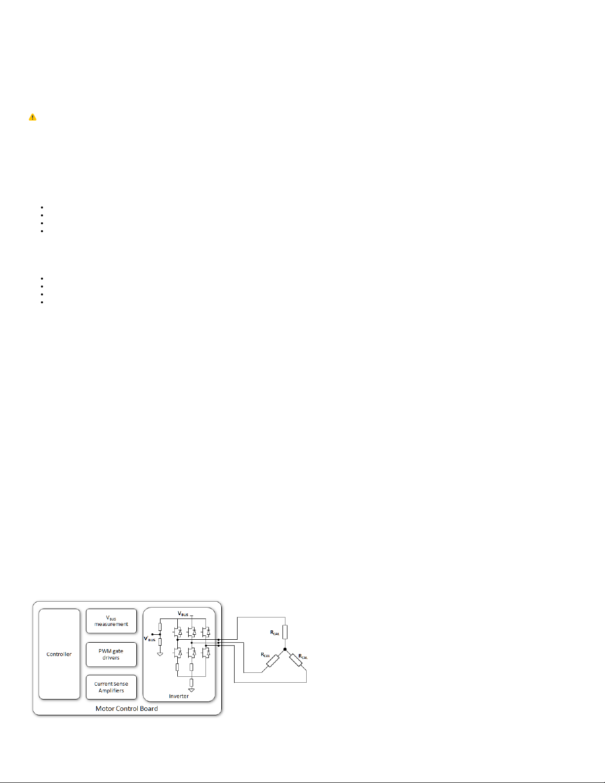
The board calibration process requires three equal-value resistors to be connected to the three-phase inverter output as shown in the diagram below.
The following equation provides the recommended range of calibration resistance values based on parameters of the board that is being calibrated:
Page 14

Where,
I
full
scale is the full-scale current for the board and
V
BUS
is the voltage applied on the inverter phase of the board.
During the calibration process, the specialized firmware applies a series of voltage pulses on the calibration resistors and measures the resulting current. The pulse train has the following
properties:
Amplitude of V
BUS
Pulse train duration of 2 ms with each pulse lasting 50 µs
Duty cycle of 46%
Since the pulses applied have an amplitude of V
BUS
, the calibration resistors must be voltage rated to handle at least half of V
BUS
. The pulse train also imposes resistor size
requirements due to the energy in the pulses that need to be dissipated with a nominal temperature rise to prevent resistance changes. Since the voltages for low and high voltage
applications vary vastly, the resistor values vary as seen below. Factoring all the above requirements we have the following values of resistors for the boards supported:
dsPICDEM™ MCLV-2 Development Board - 10 Ω and 21 millijoules
dsPICDEM™ MCHV-2 Development Board and dsPICDEM™ MCHV-3 Development Board - 50 Ω and 450 millijoules
In order to ensure accurate calibration, use resistors with
1% tolerance specification or better
Low temperature coefficient
No labels
 Loading...