

Motoplat CV-014DS User Manual
2016.09.07
Motoplat CV-0
14DS
TESTER FOR DIAGNOSTICS OF ALTERNATOR
STATOR WINDINGS AND DIODE BRIDGES
USER MANUAL
UNIQUENESS
TRAININGSERVICE
INNOVATION
WARRANTY
QUALITY


User Manual - Tester
CONTENTS
1. DESCRIPTION ....................................................................................................................................................... 4
2. TECHNICAL CHARACTERISTICS ........................................................................................................................5
3. CONTROL UNITS
4. ALTERNATOR STATOR WINDINGS TESTING ..................................................................................................7
4.1 General Information
4.2 Stator Windings Most Common Failures............................................................................................11
4.3 Stator Windings Testing Mode Operation
5. ALTERNATOR DIODE BRIDGES TESTING ........................................................................................................ 17
5.1 General Information ............................................................................................................................................... 17
5.2 Diode Bridges Most Common Failures
5.3 Diode Bridges Testing Mode Operation
.................................................................................................................................................. 6
................................................................................................................................. 7
......................................................................................... 11
......................................................................................................... 18
............................................................................................ 18
3
User Manual - Tester
1. DESCRIPTION
Motoplat CV-014DS Tester combines two devices: diagnostic tester of stator windings and diode
bridges of alternators. The device has small dimensions and a light weight, it was developed
according to the requirements of actual service stations. The feature of the tester is diagnostics
of stator windings and diode bridges with no additional testing and measuring devices.
Diagnostics of stator windings is carried out through automatic identification of phase connection,
detecting winding integrity and measuring the difference in phase distortion. The device detects
the following stator winding failures:
- inter-turn fault;
- inter-winding fault;
- winding breakdown to alternator body;
- open-phase fault.
iagnostics of diode bridges involves establishing of circuit connection of diodes and measuring
D
their operability.
iagnostic mode data appear on LCD display in real time. Stator or diode bridge testing lasts less
D
than a minute.
4

User Manual - Tester
2. TECHNICAL CHARACTERISTICS
Supply voltage, V 100-250
Supply frequency, Hz 50/60
Supply type Single-phase
Maximum consuming power, W 40
Dimensions, mm 219*214*80
Weight, kg 3
Stator windings testing
Voltage, V 12/24
Types ‘Star’, ‘delta’
- Inter-turn fault
Detected failures
- Inter-phase fault
- Phases to alternator body
- Open-phase fault
Error of measurement, % 1
Testing of short circuit to the body, kOhm 12
Diode bridges testing
Voltage, V 12/24
Current, А 30 (Pulse current)
Detected failures
-3
- Breakdown
- Open circuit
5
User Manual - Tester
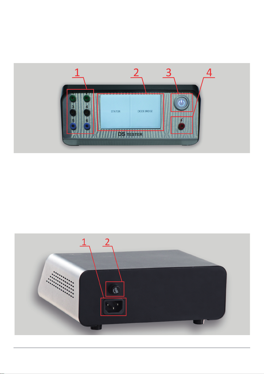
3. CONTROL UNITS
Fig. 1. Tester – Front panel
The tester is performed in black metallic frame with inclined front panel, made of stainless steel.
The front panel (Fig.1.) consists of:
1 - connection ports to connect tested stator windings or diode bridges and stator windings through
1-6 connecting cables (included in the tester set);
2 - colored LCD display;
3 - tester on/off switch;
4 - connection port to detect insulation resistance level of stator windings.
Fig. 2. Tester – Back panel
6

User Manual - Tester
The back panel (Fig. 2) consists of:
1 - mains cable connection slot;
2 - fuse (2A).
4. ALTERNATOR STATOR WINDING TESTING
4.1 G I
Stator is a fixed element of electric unit, interacting with its moving part, the rotor. It consists of
magnetically conductive core with coil windings fixed circle-wise.
Rotating inside of the stator, the rotor generates alternating current in it. The frequency of generated
alternating current equals the rotor frequency, multiplied by the number of poles (usually 6).
Description of alternator stator winding (Fig. 3):
1 - winding terminals, phases: А, В, С;
2 - stator winding;
3 - magnetically conductive core.
Fig. 3. Description of alternator stator winding
7
User Manual - Tester
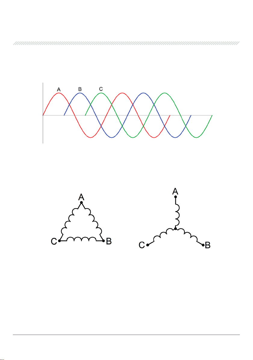
Three-phase stator winding consists of three separate windings, called phase windings or simply
phases, wound in a certain order on the magnetic core. Current phases in the windings are displaced
by one third of a period respectively one another, i.e. by 120 degrees (Fig. 4).
Fig. 4. Alternator stator winding phase displacement
Phase winding can be connected through ‘delta’ (Рic. 5, to the left) or ‘star’ diagram (Fig. 5, to the
right):
Fig. 5. Winding connection types
The windings are placed into steel frame slots, the magnetic core, to conduct magnetic flow from
the exciting winding to the stator windings directly and to reduce area dissipation of magnetic
flow. Magnetic field is created both in coils and stator magnetic core, thus, parasitic eddy currents
appear, causing loss of power and stator heating.
Thus, the magnetic core is produced from the set of steel plates (laminated iron) to reduce the
effect.
Several types of stator windings are presented below.
8
 Loading...