

Page 1

MRC Controller
ArcWorld 6200
Two-Controller
Operator's Manual
for SK-Series Robots
Part Number 133676-8
Revised 9/13/99
February 27, 1997
MOTOMAN
805 Liberty Lane
West Carrollton, OH 45449
TEL: 937-847-6200 FAX: 937-847-6277
24-HOUR SERVICE HOTLINE: 937-847-3200
The information contained within this document is the proprietary property of Motoman, Inc., and
may not be copied, reproduced or transmitted to other parties without the expressed written
Because we are constantly improving our products, we reserve the right to change specifications without
notice. MOTOMAN is a registered trademark of YASKAWA Electric Manufacturing.
authorization of Motoman, Inc.
© 1997 by MOTOMAN
All Rights Reserved
Page 2

TABLE OF CONTENTS
Section Page
LIST OF FIGURES ................................................................................................. iv
LIST OF TABLES................................................................................................... iv
1.0 INTRODUCTION.......................................................................................... 1
1.1 ABOUT THIS DOCUMENT.................................................................. 1
1.2 SYSTEM OVERVIEW............................................................................. 1
1.2.1 System Layout........................................................................... 2
1.2.2 Optional Equipment.................................................................... 3
1.3 REFERENCE TO OTHER DOCUMENTATION ...................................... 3
1.4 CUSTOMER SERVICE INFORMATION ................................................ 4
2.0 SAFETY......................................................................................................... 5
2.1 STANDARD CONVENTIONS................................................................ 6
2.2 GENERAL SAFEGUARDING TIPS........................................................ 7
2.3 MECHANICAL SAFETY DEVICES......................................................... 7
2.4 INSTALLATION SAFETY....................................................................... 8
2.5 PROGRAMMING SAFETY ................................................................... 8
2.6 OPERATION SAFETY ........................................................................... 9
2.7 MAINTENANCE SAFETY.................................................................... 10
3.0 DESCRIPTION OF EQUIPMENT ................................................................ 11
3.1 SK-SERIES ROBOT DESCRIPTION................................................... 11
3.2 MRC CONTROLLER........................................................................... 11
3.2.1 Servo Power........................................................................... 12
3.2.2 Mode Select............................................................................ 12
3.2.3 Cycle Select............................................................................ 13
3.2.4 Emergency Stop ...................................................................... 13
3.2.5 Alarm/Error............................................................................ 13
3.2.6 Hold........................................................................................ 13
3.2.7 Start....................................................................................... 13
3.2.8 Playback Box Subpanel............................................................ 13
3.3 PROGRAMMING PENDANT............................................................. 14
3.3.1 Display.................................................................................... 14
3.3.2 Robot Speed Indicators............................................................ 14
3.3.3 Emergency Stop ...................................................................... 15
3.3.4 Keypad.................................................................................... 15
3.3.5 Servo Power........................................................................... 15
3.3.6 Coordinate System Indicators.................................................. 15
ArcWorld 6200 Two-Controller Operator's Manual Page i MOTOMAN
Page 3

Section Page
3.4 MRM2-SERIES POSITIONERS.......................................................... 15
3.4.1 Welding Ground System........................................................... 17
3.4.2 Locking Pins............................................................................ 17
3.4.3 Arc Shield............................................................................... 17
3.5 OPERATOR STATION ........................................................................ 18
3.5.1 Emergency Stop...................................................................... 18
3.5.2 Hold ...................................................................................... 18
3.5.3 Cycle Start............................................................................. 18
3.5.4 Station Ready.......................................................................... 19
3.5.5 Alarm..................................................................................... 19
3.5.6 Servo On................................................................................ 19
3.5.7 Auto/Manual ........................................................................... 19
3.5.8 Master Job Start.................................................................... 19
3.5.9 Operator Station Enable/Disable.............................................. 19
3.5.10 Reset...................................................................................... 20
3.6 WELDING POWER SOURCE.............................................................. 20
3.6.1 Main Power............................................................................ 20
3.6.2 Volt/Amp Settings.................................................................... 20
3.6.3 Terminal Connectors............................................................... 21
3.6.4 Local/Remote Operation........................................................... 21
3.6.5 Feeder Control Receptacles..................................................... 21
3.6.6 Circuit Breakers..................................................................... 21
3.6.7 AC Receptacles....................................................................... 21
3.7 WELDING EQUIPMENT..................................................................... 21
3.7.1 PWF4 Wire Feeder.................................................................. 21
3.7.2 Universal Welding Interface (UWI)......................................... 22
3.7.3 MIG Torch............................................................................. 22
3.7.4 Tregaskiss Gun Mount ............................................................ 22
3.8 SAFETY EQUIPMENT ........................................................................ 22
3.8.1 Arc Screens............................................................................ 22
3.8.2 Fencing................................................................................... 23
3.8.3 Interlocks............................................................................... 23
3.8.4 Safety Mats............................................................................ 23
3.8.5 Emergency Stops..................................................................... 23
4.0 OPERATION............................................................................................... 25
4.1 OPERATING PROCEDURES.............................................................. 25
4.1.1 Start-up.................................................................................. 25
ArcWorld 6200 Two-Controller Operator's Manual Page ii MOTOMAN
Page 4

Section Page
4.1.2 Normal Operating Procedures................................................. 26
4.1.3 Emergency Stop Recovery....................................................... 26
4.1.4 Shock Sensor Recovery........................................................... 27
4.1.5 Fault Recovery........................................................................ 28
4.1.6 Shutdown................................................................................ 28
4.2 ALARMS AND ERRORS..................................................................... 28
4.2.1 Error Messages...................................................................... 28
4.2.2 Minor Alarms......................................................................... 29
4.2.3 Major Alarms......................................................................... 29
4.3 PROGRAMMING............................................................................... 29
4.3.1 Cube Assignment..................................................................... 29
4.3.2 Sweeping Positioner to Side A.................................................. 30
4.3.3 Sweeping Positioner to Side B.................................................. 31
4.3.4 Rotating Headstock ................................................................. 32
4.3.5 Programming Specific Jobs...................................................... 32
4.3.6 Rotating the Positioner During Air Cut Moves ......................... 32
4.3.7 Robot Motion with the Positioner Stationary............................ 33
4.3.8 Rotation of the Positioner During Welding................................ 33
4.3.9 Converting Programs from Side A to
Side B—Master Robot Only............................................... 33
4.3.10 I/O Assignment....................................................................... 34
4.4 SAMPLE JOBS................................................................................... 35
4.4.1 Master Controller—Master Job............................................. 35
4.4.2 Master Controller—Cube Job................................................. 36
4.4.3 Master Controller—SweepToA Job........................................ 36
4.4.4 Master Controller—SweepToB Job........................................ 37
4.4.5 Master Controller—WeldA Job.............................................. 38
4.4.6 Master Controller—WeldB Job.............................................. 39
4.4.7 Slave Controller—Cube Job.................................................... 40
4.4.8 Slave Controller—WeldA Job.................................................. 40
4.4.9 Slave Controller—WeldB Job................................................. 41
5.0 MAINTENANCE.......................................................................................... 43
5.1 PERIODIC MAINTENANCE............................................................... 43
5.2 SPARE PARTS LIST............................................................................ 44
5.3 FUSE AND CIRCUIT BREAKER PROTECTION.................................. 44
APPENDIX — RISK ASSESSMENT ....................................................... Appendix–1
INDEX
ArcWorld 6200 Two-Controller Operator's Manual Page iii MOTOMAN
Page 5

LIST OF FIGURES
Figure Page
Figure 1-1 System Layout, Top-Down View............................................................ 2
Figure 3-1 MRC Controller................................................................................ 11
Figure 3-2 MRC Playback Box............................................................................ 12
Figure 3-3 Programming Pendant....................................................................... 14
Figure 3-4 Operator Station................................................................................ 18
Figure 3-5 MotoArc Controls............................................................................. 20
LIST OF TABLES
Table Page
Table 3-1 MRM2-550 (RM2-250) Positioner Specifications............................... 16
Table 3-2 MRM2-1100 (RM2-500) Positioner Specifications............................. 16
Table 3-3 MRM2-1650 (RM2-750) Positioner Specifications............................. 17
Table 5-1 Periodic Maintenance......................................................................... 43
Table 5-2 Spare Parts....................................................................................... 44
Table 5-3 MotoArc 450 CV Fuses and Circuit Breakers..................................... 44
Table 5-4 MRC Cabinet Fuses and Circuit Breakers........................................... 45
Table 5-5 Universal Welding Interface (UWI) Fuses and Circuit Breakers.......... 46
Table 5-6 MRC System Fuses............................................................................ 46
Table 5-7 Com-Arc III Fuses and Circuit Breakers............................................ 46
ArcWorld 6200 Two-Controller Operator's Manual Page iv MOTOMAN
Page 6

1.0 INTRODUCTION
The ArcWorld 6200 Two-Controller system is part of the ArcWorld family of
standardized arc welding solutions. It is a fully integrated welding system, and is
supported from wire to weld by Motoman, Inc.
The ArcWorld 6200 features two Motoman arc welding robots, two MRC
controllers with menu-driven arc welding application software, two complete
welding packages, a 180˚ reciprocating positioner, an operator interface, and a total
safety environment.
1.1 ABOUT THIS DOCUMENT
This manual provides operation instructions for the ArcWorld 6200 TwoController system. In addition to this introduction, the manual includes the
following sections:
• SECTION 2: SAFETY
Provides information regarding the safe use and operation of the ArcWorld
6200 system.
• SECTION 3: DESCRIPTION OF EQUIPMENT
Provides a detailed description of the major components of the ArcWorld
system. This section includes a table of component specifications.
• SECTION 4: OPERATION
Provides instructions to operate the ArcWorld system. This section describes
the various operator controls and indicators. It also provides procedures for
start-up, loading, normal operation, fault recovery, and shutdown. This section
also contains a number of sample robot programs.
• SECTION 5: MAINTENANCE
Contains a table listing periodic maintenance requirements for the ArcWorld
6200 cell. It also includes a list of recommended spare parts.
• APPENDIX
The Appendix is a Risk Assessment document.
1.2 SYSTEM OVERVIEW
The ArcWorld 6200 Two-Controller system provides a complete arc welding
solution in a standardized configuration. The system is designed around two
Motoman arc welding robots and two MRC controllers, and includes two
complete welding packages. A dual station reciprocating positioner allows an
operator to prepare and set up parts on one side while the robots weld on the other
side. The cell provides a full complement of safety features designed to protect
both personnel and equipment.
ArcWorld 6200 Two-Controller Operator's Manual Page 1 MOTOMAN
Page 7
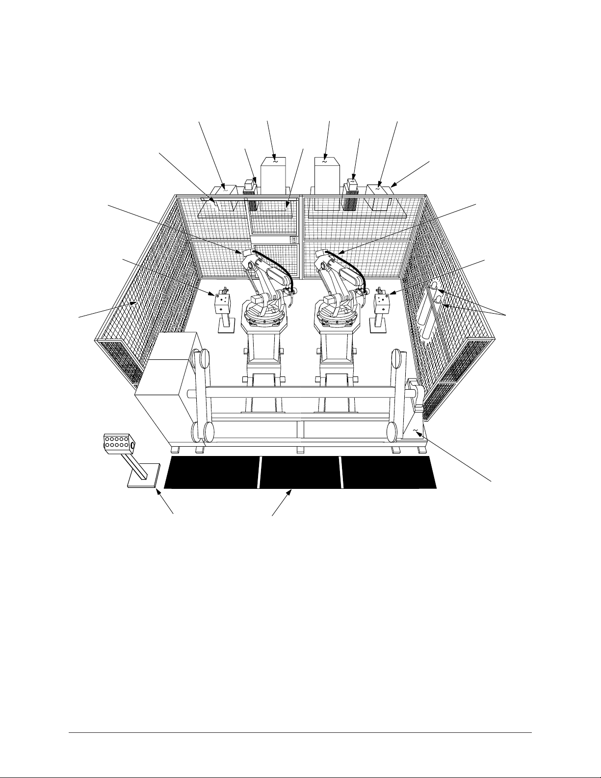
1.2.1 System Layout
Figure 1-1 shows a top-down view of the system layout for the ArcWorld 6200
Two-Controller cell.
Master
Robot
Assembled
Safety
Fence
T orch
T ender
MotoArc Welding
Power Source
Disconnect
Master Controller
MRC Cabinet
Water
Circulator
Slave Controller
MRC Cabinet
Cell
Door
MotoArc Welding
Power Source
Com-Arc III
Auxiliary Equipment
Common Base
Slave
Robot
T orch
T ender
Gas Bottles
(customer
supplied)
Positioner
Operator
Station
Safety Mat
Figure 1-1 System Layout, Top-Down View
The ArcWorld 6200 Two-Controller cell includes the following major components:
• Two Motoman robot manipulators
• Two MRC controllers
• MRM2-series dual station reciprocating positioner
• Master operator station
• Welding equipment, including the following:
— Two MotoArc welding power sources
— Two torches (water-cooled or air-cooled)
ArcWorld 6200 Two-Controller Operator's Manual Page 2 MOTOMAN
Page 8

— Two wire feeders
— Two universal welding interfaces (UWIs)
— Two Tregaskiss gun mounts
• Safety equipment, including the following:
— Safety fencing with arc curtains
— Interlocked safety mats
— Interlocked cell door
— Positioner arc screen
The robot manipulators and positioner share a common base for ease of installation
and to help maintain proper alignment between these components. Each MRC
controller shares a common base with its welding power source. Additional
auxiliary components, such as the water circulator and the Com-Arc III seam
tracking unit, can be located on the bases with the controllers.
NOTE: Arc shield on positioner and arc curtains not shown for clarity.
The robotic cell is fully enclosed by safety fencing and is entered only through an
interlocking door. Safety mats prevent the positioner from cycling while anyone is
standing directly on the mats. All operator controls, including those on the MRC
and welding power supply, are accessible from outside of the safety fencing that
encloses the robotic cell.
1.2.2 Optional Equipment
The following optional equipment is available for use with the ArcWorld 6200:
• Torch tender
• Wire cutter
• Com-Arc III through-the-arc seam tracking unit
• Heavy duty positioners
• Stationary tables
1.3 REFERENCE TO OTHER DOCUMENTATION
For additional information refer to the following:
• Motoman SK6 Manipulator Manual (P/N 133680-2)
• Motoman SK16 Manipulator Manual (P/N 133680-3)
• Motoman MRC Operator’s Manual for Arc Welding (P/N 132332-1)
• Motoman MRC User Functions Manual (P/N 132331-1)
• Motoman ArcWorld 6200 Installation Manual (P/N 133677-8)
• Motoman MRC Operator’s Manual for Jigless (P/N 132332-3)
• Com-Arc III Instruction Manual (P/N 132753-1)
• Vendor manuals for system components not manufactured by Motoman
ArcWorld 6200 Two-Controller Operator's Manual Page 3 MOTOMAN
Page 9

1.4 CUSTOMER SERVICE INFORMATION
If you need technical assistance, contact the Motoman service staff at
(937) 847-3200. Please have the following information ready before you call:
• Robot Type (SK6 or SK16)
• Serial Number (located on the back side of the robot arm)
• Application Type (welding)
• Order Numbers (located on back side of robots and MRC controllers)
ArcWorld 6200 Two-Controller Operator's Manual Page 4 MOTOMAN
Page 10

2.0 SAFETY
It is the purchaser's responsibility to ensure that all local, county,
state, and national codes, regulations, rules, or laws relating to
safety and safe operating conditions for each installation are met
and followed.
We suggest that you obtain and review a copy of the ANSI/RIA National Safety
Standard for Industrial Robots and Robot Systems. This information can be
obtained from the Robotic Industries Association by requesting ANSI/RIA
R15.06. The address is as follows:
Robotic Industries Association
900 Victors Way
P.O. Box 3724
Ann Arbor, Michigan 48106
TEL: 313/994-6088
FAX: 313/994-3338
Ultimately, the best safeguard is trained personnel. The user is responsible for
providing personnel who are adequately trained to operate, program, and maintain
the robot cell. The robot must not be operated by personnel who have not
been trained!
We recommend that all personnel who intend to operate, program, repair, or use
the robot system be trained in an approved Motoman training course and become
familiar with the proper operation of the system.
This safety section addresses the following:
• Standard Conventions (Section 2.1)
• General Safeguarding Tips (Section 2.2)
• Mechanical Safety Devices (Section 2.3)
• Installation Safety (Section 2.4)
• Programming Safety (Section 2.5)
• Operation Safety (Section 2.6)
• Maintenance Safety (Section 2.7)
ArcWorld 6200 Two-Controller Operator's Manual Page 5 MOTOMAN
Page 11

2.1 STANDARD CONVENTIONS
This manual includes information essential to the safety of personnel and
equipment. As you read through this manual, be alert to the four signal words:
• DANGER
• WARNING
• CAUTION
• NOTE
Pay particular attention to the information provided under these headings which are
defined below (in descending order of severity).
DANGER!
Information appearing under the DANGER caption concerns the
protection of personnel from the immediate and imminent
hazards that, if not avoided, will result in immediate, serious
personal injury or loss of life in addition to equipment damage.
WARNING!
Information appearing under the WARNING caption concerns the
protection of personnel and equipment from potential hazards
that can result in personal injury or loss of life in addition to
equipment damage.
CAUTION!
Information appearing under the CAUTION caption concerns the
protection of personnel and equipment, software, and data from
hazards that can result in minor personal injury or equipment
damage.
NOTE: Information appearing in a NOTE caption provides additional information which is helpful in
understanding the item being explained.
ArcWorld 6200 Two-Controller Operator's Manual Page 6 MOTOMAN
Page 12

2.2 GENERAL SAFEGUARDING TIPS
All operators, programmers, plant and tooling engineers, maintenance personnel,
supervisors, and anyone working near the robot must become familiar with the
operation of this equipment. All personnel involved with the operation of the
equipment must understand potential dangers of operation. General safeguarding
tips are as follows:
• Improper operation can result in personal injury and/or damage to the
equipment. Only trained personnel familiar with the operation of this robot, the
operator's manuals, the system equipment, and options and accessories should
be permitted to operate this robot system.
• Do not enter the robot cell while it is in automatic operation. Programmers
must have the teach pendant when they enter the robot cell.
• Improper connections can damage the robot. All connections must be made
within the standard voltage and current ratings of the robot I/O (Inputs and
Outputs).
• The robot must be placed in Emergency Stop (E-Stop) mode whenever it is not
in use.
• In accordance with ANSI/RIA R15.06, section 6.13.4 and 6.13.5, use
lockout/tagout procedures during equipment maintenance. Refer also to Section
1910.147 (29CFR, Part 1910), Occupational Safety and Health Standards for
General Industry (OSHA).
2.3 MECHANICAL SAFETY DEVICES
The safe operation of the robot, positioner, auxiliary equipment, and system is
ultimately the user's responsibility. The conditions under which the equipment will
be operated safely should be reviewed by the user. The user must be aware of the
various national codes, ANSI/RIA R15.06 safety standards, and other local codes
that may pertain to the installation and use of industrial equipment. Additional
safety measures for personnel and equipment may be required depending on
system installation, operation, and/or location. The following safety measures are
available:
• Safety fences and barriers
• Light curtains
• Door interlocks
• Safety mats
• Floor markings
• Warning lights
Check all safety equipment frequently for proper operation. Repair or replace any
non-functioning safety equipment immediately.
ArcWorld 6200 Two-Controller Operator's Manual Page 7 MOTOMAN
Page 13

2.4 INSTALLATION SAFETY
Safe installation is essential for protection of people and equipment. The following
suggestions are intended to supplement, but not replace, existing federal, local, and
state laws and regulations. Additional safety measures for personnel and
equipment may be required depending on system installation, operation, and/or
location. Installation tips are as follows:
• Be sure that only qualified personnel familiar with national codes, local codes,
and ANSI/RIA R15.06 safety standards are permitted to install the equipment.
• Identify the work envelope of each robot with floor markings, signs, and
barriers.
• Position all controllers outside the robot work envelope.
• Whenever possible, install safety fences to protect against unauthorized entry
into the work envelope.
• Eliminate areas where personnel might get trapped between a moving robot and
other equipment (pinch points).
• Provide sufficient room inside the workcell to permit safe teaching and
maintenance procedures.
2.5 PROGRAMMING SAFETY
All operators, programmers, plant and tooling engineers, maintenance personnel,
supervisors, and anyone working near the robot must become familiar with the
operation of this equipment. All personnel involved with the operation of the
equipment must understand potential dangers of operation. Programming tips are
as follows:
• Any modifications to PART 1 of the MRC controller PLC can cause severe
personal injury or death, as well as damage to the robot! Do not make any
modifications to PART 1. Making any changes without the written permission
of Motoman will VOID YOUR WARRANTY!
• Some operations require standard passwords and some require special
passwords. Special passwords are for Motoman use only. YOUR
WARRANTY WILL BE VOID if you use these special passwords.
• Back up all programs and jobs onto a floppy disk whenever program changes
are made. To avoid loss of information, programs, or jobs, a backup must
always be made before any service procedures are done and before any changes
are made to options, accessories, or equipment.
• The concurrent I/O (Input and Output) function allows the customer to modify
the internal ladder inputs and outputs for maximum robot performance. Great
care must be taken when making these modifications. Double-check all
modifications under every mode of robot operation to ensure that you have not
created hazards or dangerous situations that may damage the robot or other
parts of the system.
• Improper operation can result in personal injury and/or damage to the
equipment. Only trained personnel familiar with the operation, manuals,
electrical design, and equipment interconnections of this robot should be
permitted to operate the system.
ArcWorld 6200 Two-Controller Operator's Manual Page 8 MOTOMAN
Page 14

• Inspect the robot and work envelope to be sure no potentially hazardous
conditions exist. Be sure the area is clean and free of water, oil, debris, etc.
• Be sure that all safeguards are in place.
• Check the E-STOP button on the teach pendant for proper operation before
programming.
• Carry the teach pendant with you when you enter the workcell.
• Be sure that only the person holding the teach pendant enters the workcell.
• Test any new or modified program at low speed for at least one full cycle.
2.6 OPERATION SAFETY
All operators, programmers, plant and tooling engineers, maintenance personnel,
supervisors, and anyone working near the robot must become familiar with the
operation of this equipment. All personnel involved with the operation of the
equipment must understand potential dangers of operation. Operation tips are as
follows:
• Be sure that only trained personnel familiar with the operation of this robot, the
operator's manuals, the system equipment, and options and accessories are
permitted to operate this robot system.
• Check all safety equipment for proper operation. Repair or replace any nonfunctioning safety equipment immediately.
• Inspect the robot and work envelope to ensure no potentially hazardous
conditions exist. Be sure the area is clean and free of water, oil, debris, etc.
• Ensure that all safeguards are in place.
• Improper operation can result in personal injury and/or damage to the
equipment. Only trained personnel familiar with the operation, manuals,
electrical design, and equipment interconnections of this robot should be
permitted to operate the system.
• Do not enter the robot cell while it is in automatic operation. Programmers
must have the teach pendant when they enter the cell.
• The robot must be placed in Emergency Stop (E-Stop) mode whenever it is not
in use.
• This equipment has multiple sources of electrical supply. Electrical
interconnections are made between the controller, external servo box, and other
equipment. Disconnect and lockout/tagout all electrical circuits before making
any modifications or connections.
• All modifications made to the controller will change the way the robot operates
and can cause severe personal injury or death, as well as damage the robot. This
includes controller parameters, ladder parts 1 and 2, and I/O (Input and Output)
modifications. Check and test all changes at slow speed.
ArcWorld 6200 Two-Controller Operator's Manual Page 9 MOTOMAN
Page 15

2.7 MAINTENANCE SAFETY
All operators, programmers, plant and tooling engineers, maintenance personnel,
supervisors, and anyone working near the robot must become familiar with the
operation of this equipment. All personnel involved with the operation of the
equipment must understand potential dangers of operation. Maintenance tips are as
follows:
• Do not perform any maintenance procedures before reading and understanding
the proper procedures in the appropriate manual.
• Check all safety equipment for proper operation. Repair or replace any nonfunctioning safety equipment immediately.
• Improper operation can result in personal injury and/or damage to the
equipment. Only trained personnel familiar with the operation, manuals,
electrical design, and equipment interconnections of this robot should be
permitted to operate the system.
• Back up all your programs and jobs onto a floppy disk whenever program
changes are made. A backup must always be made before any servicing or
changes are made to options, accessories, or equipment to avoid loss of
information, programs, or jobs.
• Do not enter the robot cell while it is in automatic operation. Programmers
must have the teach pendant when they enter the cell.
• The robot must be placed in Emergency Stop (E-Stop) mode whenever it is not
in use.
• Be sure all safeguards are in place.
• Use proper replacement parts.
• This equipment has multiple sources of electrical supply. Electrical
interconnections are made between the controller, external servo box, and other
equipment. Disconnect and lockout/tagout all electrical circuits before making
any modifications or connections.
• All modifications made to the controller will change the way the robot operates
and can cause severe personal injury or death, as well as damage the robot.
This includes controller parameters, ladder parts 1 and 2, and I/O (Input and
Output) modifications. Check and test all changes at slow speed.
• Improper connections can damage the robot. All connections must be made
within the standard voltage and current ratings of the robot I/O (Inputs and
Outputs).
ArcWorld 6200 Two-Controller Operator's Manual Page 10 MOTOMAN
Page 16
3.0 DESCRIPTION OF EQUIPMENT
3.1 SK-SERIES ROBOT DESCRIPTION
The Motoman SK6 and SK16 robots and MRC controller represent state-of-theart technology in robotics today. The six-axis SK6 robot has a payload of 6 kg
(13.2 lbs). It features a 1,325 mm (52.1 in.) reach and has a relative positioning
accuracy of ± 0.1 mm (0.004 in.). The six-axis SK16 robot has a payload of
16 kg (35.2 lbs). It features a 1,555 mm (61.2 in.) reach and has a relative
positioning accuracy of ± 0.1 mm (0.004 in.).
Each robot can reach below its own base as well as behind itself. These robots can
also be mounted in floor, wall, or ceiling configurations with few hardware
modifications. The replacement life for the lithium battery is approximately three
years.
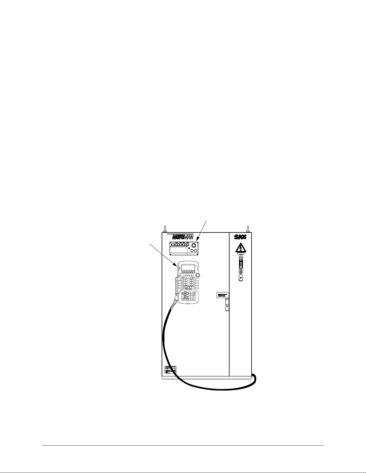
3.2 MRC CONTROLLER
The MRC controller (see Figure 3-1) coordinates the operation of the ArcWorld
system. It controls the movement of the manipulator, processes input and output
signals, controls the operation of the welding power supply, and provides the
signals to operate the welding system. The ArcWorld 6200 Two-Controller
system is configured so that each controller directs the action of its respective robot.
PROGRAMMING PENDANT
SERVO POWER
YASNAC MRC
MODE
CYCLE
E.STOP
REMOTETEACHPLAY
1 CYCLE
STEP
AUTO
S
E
R
T
E
S
E
R
ALARM/
ERROR
HOLD
PLAYBACK BOX
E
T
R
E
S
E
T
START
WARNING
480 VOLTS
Figure 3-1 MRC Controller
ArcWorld 6200 Two-Controller Operator's Manual Page 11 MOTOMAN
Page 17
The Master controller coordinates the operation of the entire cell and directs the
action of the Master robot manipulator. The Slave controller directs the action
of the Slave robot manipulator. The Master controller delegates tasks to the Slave
controller and monitors task completion by sending output to and receiving output
from the Slave controller.
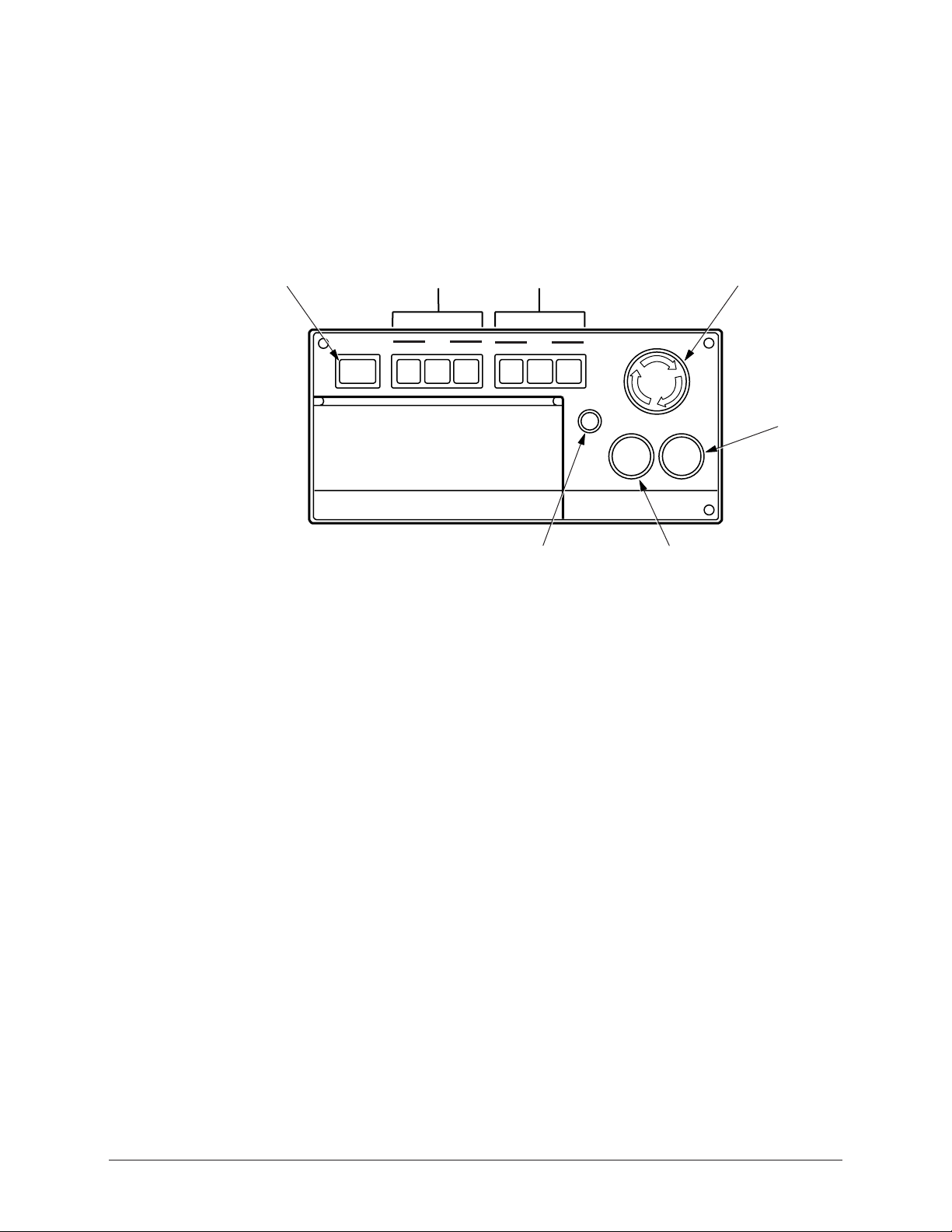
The playback box (see Figure 3-2) has the primary system controls for the MRC.
Control buttons are grouped on the front panel and the subpanel. The following
paragraphs describe the MRC controls.
SERVO
POWER
3.2.1 Servo Power
On each MRC, the SERVO POWER button on the front panel turns on the robot
servo power to the robot controlled by that controller. An indicator lamp in the
switch lights when servo power is on. The SERVO POWER button on one
controller does NOT turn on servo power to the other controller or its robot. Only
by pressing the SERVO ON button on the operator station can you turn on servo
power of both the Master and Slave controllers at the same time.
SERVO POWER
MODE
BUTTONS
MODE
REMOTETEACHPLAY
CYCLE
BUTTONS
CYCLE
1 CYCLE
AUTO
STEP
ALARM/
ERROR
HOLD
ALARM/ERROR
INDICATOR
Figure 3-2 MRC Playback Box
E.STOP
S
E
R
T
E
S
E
R
HOLD
BUTTON
E-STOP
E
T
R
E
S
E
T
START
START
BUTTON
3.2.2 Mode Select
The MODE SELECT buttons (PLAY, TEACH, and REMOTE) set the robot’s
mode of operation. Indicator lamps light to show the current mode of operation.
Pressing the TEACH or REMOTE button on one controller will also place the
other MRC controller into the TEACH or REMOTE mode. The PLAY mode
button on the Slave controller has been disabled to allow for a single point of
control and added safety; however, pressing the PLAY mode button on the Master
controller WILL place the Slave controller into the PLAY mode. Refer to your
MRC Operator’s Manual for more information.
ArcWorld 6200 Two-Controller Operator's Manual Page 12 MOTOMAN
Page 18

3.2.3 Cycle Select
The CYCLE SELECT button switches (AUTO, 1-CYCLE, and STEP) set the
operating method for playback operations. Indicator lamps in the CYCLE
SELECT switches light to show the selected playback method. These buttons need
to be set individually on each MRC controller. In other words, pressing the AUTO
switch on one controller does NOT place the other controller into the AUTO cycle
mode. These buttons should typically be set the same on both controllers. Refer to
your MRC Operator’s Manual for more information.
3.2.4 Emergency Stop
The Emergency Stop (E-STOP) button is connected to the system Emergency
Stop circuit. Interrupting the Emergency Stop circuit causes the robot to go into the
Emergency Stop condition. Pressing the E-STOP button on EITHER CONTROLLER immediately cuts servo power and engages the brakes on BOTH
ROBOTS and the positioner.
3.2.5 Alarm/Error
The ALARM/ERROR indicator lights whenever an alarm or error condition
occurs. The indicator also lights when servo power is cut to the system, as in the
case of an E-STOP condition. After you reset the alarm or error condition or
restore servo power, the indictor lamp turns off.
3.2.6 Hold
Pressing the HOLD button on EITHER CONTROLLER stops the operation of
BOTH robot manipulators and the positioner momentarily. The indicator lamps
light whenever the robots are in a HOLD state. The RESET button on the operator
station must be pressed to clear the HOLD state. Then the MASTER JOB START
button on the operator station must be pressed in order to start both robots at the
same time. Operation will resume at the point in the program where the HOLD
state was initiated. The HOLD button is normally closed. Refer to your MRC
Operator’s Manual for more information.
CAUTION!
If instead of pressing the MASTER JOB START button on the
operator station, you press the green START button on either
playback box, only that robot will start. This could lead to a
possible crash with the other robot.
3.2.7 Start
Pressing the START button on one MRC controller causes the manipulator
playback operation to start ONLY for that controller. In other words, pressing the
START button on the Master controller will NOT cause the Slave controller to start
and vice versa. The indicator lamp lights during playback. The MASTER JOB
START button on the operator station is used to start both controllers at the same
time. This is explained later in the manual.
3.2.8 Playback Box Subpanel
The playback box has a subpanel that contains additional user controls. Refer to
your MRC Operator’s Manual for more information.
ArcWorld 6200 Two-Controller Operator's Manual Page 13 MOTOMAN
Page 19

3.3 PROGRAMMING PENDANT
The programming pendant (see Figure 3-3) provides the primary user interface
with the system. The pendant has a 12-line LCD display and keypad. The system
uses the INFORM robot language and a menu driven interface to simplify operator
interaction with the robot. By using the pendant, the operator can teach the robot a
series of motions and perform programming, editing, maintenance, and diagnostic
functions. The pendants for both the Master and Slave manipulators can be
programmed at the same time, reducing the time needed to teach jobs to the
manipulators.
COORDINATE
SYSTEM
INDICATORS
SERVO
POWER ON
COORD
USER
YASNAC MRC
S:
J:
JOINT
WLD
CYL
TOOL
=>
!
F2
SERVO
POWER ON
F1
DISP EDIT SELECT
GROUP
AXIS
ENABLE
X- X+
1
Y-
2
Z-
3
GROUP
AXIS
MODIFY
CANCEL
MOTION
TYPE
S-
L- L+
U-
RELEASE
DELETE
PLAY
SPD
S+
Y+
Z+
U+
HOLD
TEACH AUTO
F3
HIGH
COORD
SPD
TEST
START
INSERT MODIFY
7
WEAV ON
4
WEAV OFF
1
TIMER
0
POS
REF PNT
LVL
F4 F5
FUNC
SLW FST
x
R-
y
B- B+
z
T-
BWD
8
ARC ON FEED
5
ARC OFF RETRACT
2
VOLT
.
VOLT
STOP
CUSTOMER
MAN SPD
x
R+
y
z
T+
FWD
ENTER
MORE
E.STOP
9
6
3
CUR
-
CUR
DISPLAY
MAN SPD
FST
MED
SLW
INCHING
S
E
E
T
R
T
E
S
E
R
R
E
S
E
T
ROBOT
SPEED
INDICATORS
E-STOP
4
5
6
KEYPAD
Figure 3-3 Programming Pendant
3.3.1 Display
The programming pendant has a 12-line LCD display. The display provides status
information, system messages and prompts, and a graphic work area. Refer to
your MRC Operator’s Manual for more information.
3.3.2 Robot Speed Indicators
The MAN SPD (Manipulator Speed) indicators light to show the speed of the
selected robot manipulator. SLW indicates slow speed and FST indicates fast.
ArcWorld 6200 Two-Controller Operator's Manual Page 14 MOTOMAN
Page 20

3.3.3 Emergency Stop
The E-STOP button is connected to the system Emergency Stop circuit.
Interrupting the Emergency Stop circuit from EITHER PENDANT causes BOTH
robots to go into the Emergency Stop condition. Pressing the E-STOP button on
EITHER PENDANT immediately cuts servo power and engages the brakes on
BOTH robots and on the positioner.
3.3.4 Keypad
The user keypad on the programming pendant serves as an input device. The keys
are grouped into different functional sections to simplify operator use. For more
information, refer to your MRC Operator’s Manual.
3.3.5 Servo Power
The SERVO POWER button switch turns on the robot servo power. An indicator
lamp in the switch lights when servo power is on. The SERVO POWER button
on one controller will NOT turn on servo power to the other MRC controller.
NOTE: The SERVO POWER button on the Master controller also turns on servo power to
the positioner.
3.3.6 Coordinate System Indicators
The COORD indicators light to show the currently active coordinate system.
3.4 MRM2-SERIES POSITIONERS
The ArcWorld 6200 cell uses one of three different reciprocating positioners: the
MRM2-550 (RM2-250), the MRM2-1100 (RM2-500), or the MRM2-1650
(RM2-750). The MRM2-series positioners are AC servo controlled by the Master
robot to provide coordinated motion while welding or between welds. The
standard distance between the headstock and tailstock faceplates on the MRM2-550
(RM2-250) positioner is 2.6 meters (approximately 102 in.). The standard distance
between the headstock and tailstock faceplates on the MRM2-1100 (RM2-500) and
MRM2-1650 (RM2-750) positioners is 3.0 meters (approximately 118 in.).
Tables 3-1, 3-2, and 3-3 provide specifications for the MRM2-550, MRM2-1100,
and MRM2-1650 positioners, respectively. The load side of the positioner is fixed
for loading and unloading parts. The patented servo motor is used to sweep the
positioner workstations into and out of the robot envelope, and also to turn the weld
side of the positioner during welding.
A fixture frame is typically mounted between the headstock and tailstock faceplates
to provide a highly flexible system. Fixtures are either mounted on or integrated to
these frames for positioning and clamping of production parts. Pneumatic and
electrical signals can be run to the fixtures if required. Depending on part size(s)
and weight(s), you can mount single, multiple, or a combination of parts to the
fixture frame.
The ArcWorld 6200 system is capable of synchronized motion between the Master
robot and the positioner only; the Master robot and positioner move at the same
time to do the welding. The system is also capable of coordinated motion between
the Master robot and the positioner only, where the positioner rotates the parts
while the Master robot does the welding. The Slave controller is not coordinated
with the positioner or with the Master robot.
ArcWorld 6200 Two-Controller Operator's Manual Page 15 MOTOMAN
Page 21

NOTE: In high humidity areas, use surface protection to prevent corrosion of the tooling plates.
Table 3-1 MRM2-550 (RM2-250) Positioner Specifications
Capacity
Maximum Weight
Differential per Side
Swing Diameter
Temperature Operating
Range
Humidity
Shock Rating
Sweep Speed
(Torque/Time)
Servo Headstock Speed
(Torque/ Speed)
Air Requirements
Electrical Requirements
Welding Current Rating
249.5 kg (550 lbs) combined part/fixture weight per side
499 kg (1100 lbs) total
190.6 kg (375 lbs)
0.98 m (37.4 in.)
4–43°C (40–110°F)
Non-condensing 10–90% relative humidity
Less than 0.5 G
1000 Nm/4 sec.
1050 Nm/0 - 16.8 rpm
80 psi
24 VDC for interface
208 VAC, 6.2 amp
Positioner power supplied by the MRC controller
700 amperes at 100% duty cycle
Table 3-2 MRM2-1100 (RM2-500) Positioner Specifications
Capacity
Maximum Weight
Differential per Side
Swing Diameter
Temperature Operating
Range
Humidity
Shock Rating
Sweep Speed
(Torque/Time)
Servo Headstock Speed
(Torque/ Speed)
Air Requirements
Electrical Requirements
Welding Current Rating
499 kg (1100 lbs) combined part/fixture weight per side
998 kg (2200 lbs) total
289.8 kg (639 lbs)
1.1 m (43.3 in.)
4–43°C (40–110°F)
Non-condensing 10–90% relative humidity
Less than 0.5 G
2000 Nm/5 sec.
1050 Nm/0 - 16.8 rpm
80 psi
24 VDC for interface
208 VAC, 9.0 amp
Positioner power supplied by the MRC controller
800 amperes at 100% duty cycle
ArcWorld 6200 Two-Controller Operator's Manual Page 16 MOTOMAN
Page 22

Table 3-3 MRM2-1650 (RM2-750) Positioner Specifications
Capacity
Swing Diameter
Temperature Operating
Range
Humidity
Shock Rating
Sweep Speed
(Torque/Time)
Servo Headstock Speed
(Torque/Speed)
Air Requirements
Electrical Requirements
Welding Current Rating
750 kg (1650 lbs) combined part/fixture weight per side
1500 kg (3300 lbs) total
1.3 m (51.2 in.)
4–43°C (40–110°F)
Non-condensing 10–90% relative humidity
Less than 0.5 G
2770 Nm/8 sec.
900–1100 Nm/9 rpm
80 psi
24 VDC for interface
208 VAC, 9.0 amp
Positioner power supplied by the MRC controller
800 amperes at 100% duty cycle
3.4.1 Welding Ground System
The welding ground system consists of a spring-loaded copper brush that contacts
a ring mounted behind the surface of the faceplate. The ground cable to the welding
power source is connected to the ground stud located on the right side of the
positioner base as you face the back of the ArcWorld 6200 cell.
CAUTION!
The ground cable connection to the insulated stud must be tight.
If the connection is loose, arcing can occur and cause the
insulator to melt.
3.4.2 Locking Pins
The MRM2-series positioners are equipped with fixture locking pins that prevent
the headstock/tailstock faceplates from turning when the servo motor retracts. The
fixture locking pins are spring loaded, so when the servo motor withdraws, the pins
engage. Each headstock and tailstock faceplate on the RM2-series positioners has
one locking pin.
The MRM2-1100 (RM2-500) and MRM2-1650 (RM2-750) positioners are also
equipped with a pair of sweep lock drive pins that prevent the sweep axis from
turning during the welding and loading cycles. One sweep lock drive pin is located
on the headstock drive base and the other is located on the tailstock drive base.
3.4.3 Arc Shield
CAUTION!
Do not operate this system unless the arc shield is in place.
The MRM2-series positioners are provided with a sheet metal screen for arc
radiation protection between the operator loading zone and the welding zone.
ArcWorld 6200 Two-Controller Operator's Manual Page 17 MOTOMAN
Page 23

3.5 OPERATOR STATION
T
The operator station (OP-station) includes a NEMA enclosure on a stand-alone
pedestal. The following paragraphs describe each of the OP-station controls.
CYCLE START
ALARM
RESET
3.5.1 Emergency Stop
ROBOT HOLD
MASTER JOB
START
MOTOMAN
STATION READY
POSITIONER
AUTO/MAN
WARNING!
OPERATOR STATION
ENABLE/DISABLE
ESTOP
SERVO ON
Figure 3-4 Operator Station
CYCLE STAR
The operator station E-STOP, the robot E-STOP, the sliding door interlocks, and
the ArcWorld 6200 safety mats are connected in series in the Emergency Stop
circuit. If the Emergency Stop circuit is interrupted, the robots and the Motoman
MRM2-series positioner will go into the Emergency Stop condition and all table
motion stops. The operator station E-STOP light will come on when the E-STOP
button is pressed.
3.5.2 Hold
The operator station HOLD button is a normally closed button connected to both
MRC controllers. Both robots and the positioner go into the HOLD condition
when this button is pressed.
3.5.3 Cycle Start
The palm buttons in the operator station use an anti-tiedown technique for robot
input. The anti-tiedown timer is set for 10 seconds. Holding the palm buttons
down for more than 10 seconds causes the system to time out and prevents the
CYCLE START input from reaching the robot a second time after the initial start.
The CYCLE START buttons are connected to robot Input #1 on the Master
controller only.
ArcWorld 6200 Two-Controller Operator's Manual Page 18 MOTOMAN
Page 24

3.5.4 Station Ready
The STATION READY lamp is interlocked with the robot Cube #1 output (safe
position). When the robots are in Cube #1, Output #1 in the Master controller turns
on the STATION READY lamp. Refer to your MRC User Functions and
Operator’s Manuals for more information about the cube function.
3.5.5 Alarm
The ALARM lamp is connected to the Master robot ALARM OCCURRENCE
output. The ALARM lamp turns on when EITHER robot encounters a major or
minor alarm condition or when power is cut to the servos.
3.5.6 Servo On
The SERVO ON button is connected to the robot SERVO ON input on both
controllers. The servo motors on both robots will turn on when all four of these
conditions are met:
• The SERVO ON button is pressed
• Air is supplied to the positioner
• An Emergency Stop condition does not exist
• The operator station is enabled
3.5.7 Auto/Manual
The function of this button is dependent on the structure of the Master job.
The selector switch is connected to robot Input #2 on the Master controller only.
The AUTO/MANUAL selector switch is used to select AUTOMATIC or
MANUAL mode for the positioners. When the selector switch is in the
AUTOMATIC position, the robot will process the part after the positioner sweeps.
In MANUAL mode, the robot will not process the part after the positioner sweeps,
but will return the robot to the home position to wait until CYCLE START buttons
are pressed. Examples of how to use this switch are shown later in the manual.
3.5.8 Master Job Start
The MASTER JOB START button is connected to the robot external start input on
both the Master and Slave controllers. The robots will start the current active job,
once the MASTER JOB START is pressed, as long as
• The robots are in PLAY mode
• The operator station is enabled
• The servo motors are on
• All HOLDS and ALARMS are reset
3.5.9 Operator Station Enable/Disable
The OPERATOR STATION ENABLE/DISABLE selector switch is used to
transfer primary control of the ArcWorld cell from the MRC to the operator station.
The REMOTE MODE buttons on the MRC playback boxes light when the
operator station is enabled. Most programming pendant functions are disabled
while in REMOTE.
ArcWorld 6200 Two-Controller Operator's Manual Page 19 MOTOMAN
Page 25

3.5.10 Reset
The RESET button is connected to the robot alarm reset input on both controllers.
A minor alarm or error condition will be cleared when this button is pressed. In
addition, the RESET button and the RIGHT CYCLE START buttons are
interlocked and, when pressed simultaneously, enable the MRM2-series positioner
if the robot servo motors are on. The entire robotic cell needs to be enabled at initial
power up or after an Emergency Stop or Shock Sensor condition.
3.6 WELDING POWER SOURCE
The MotoArc 450 power source (see Figure 3-5) is a constant-voltage,
transformer-rectifier, welding power supply. It provides volt-current characteristic
curves that are essentially flat. This power source can be used with most MIG
applications from thin sheet metal to heavy gauge plate.
The MotoArc 450 is the standard power source configuration for the ArcWorld
cell. Other models are available to meet the client company’s needs. These include
the MotoArc 350i, MotoArc 500i, and MotoArc 650.
12
5
6
4
3
INPUT
V
POWER
LOCAL
REMOTE
ON
OFFIO
7
6
7
2
1
9
0
10
3
A
8
V
8
WIRE FEED#1 WIRE FEED#2
REMOTE
CONTROL
CIRCUIT BREAKERS
10 AMPS 10 AMPS
110 V 9A
9
10
11
4
5
CC CV
1 Main Power Pilot Light 8 Feeder Cont. Receptacle Panel
2 Welding Voltage/Amperage Control 9 10 A Circuit Breaker
3 Volt/Amp Meter and Switch 10 10 A Circuit Breaker
4 Positive Terminal 11 115 V AC Receptacle
5 Negative Terminal
6 Local/Remote Output Control Select.
7 Input Power Switch
Figure 3-5 MotoArc Controls
3.6.1 Main Power
The INPUT POWER Switch (7, Figure 3-5) turns on the main power. The main
power must be on before any other section of the power source can operate. The
Main Power Pilot Light (1) illuminates when main power is on.
3.6.2 Volt/Amp Settings
The Welding Voltage/Amperage Control (2, Figure 3-5) adjusts the welding output
and open circuit voltage. The Volt/Amp Meter and Switch (3) display either DC
voltage or DC current depending on the position of the switch. Refer to your
MotoArc manual for additional information.
ArcWorld 6200 Two-Controller Operator's Manual Page 20 MOTOMAN
Page 26

3.6.3 Terminal Connectors
The two terminals on the front of the MotoArc power source serve as connection
points for the welding leads. The Positive Terminal (4, Figure 3-5) connects
positive welding lead (to the wire feeder). The Negative Terminal (5) connects to
the negative welding lead (to the positioner ground lug).
3.6.4 Local/Remote Operation
The LOCAL/REMOTE Output Control Selector Switch (6, Figure 3-5) sets
the mode of operation for the power source. For ArcWorld applications,
this switch should be set to REMOTE. Refer to your MotoArc manual for
additional information.
3.6.5 Feeder Control Receptacles
The Feeder Control Receptacle Panel (8, Figure 3-5) located in the back of the
power source provides connectors for use with remote voltage control applications.
For ArcWorld applications, the MRC connects to the 19-pin connector.
3.6.6 Circuit Breakers
The MotoArc power source uses two 10-amp Circuit Breakers (9 and 10,
Figure 3-5). One circuit breaker protects the 24-volt circuit, the other protects the
115-volt circuit.
3.6.7 AC Receptacles
The MotoArc unit has two standard 115 V AC Receptacles (11, Figure 3-5). These
provide auxiliary power at a maximum current of 10 amps. For applications using
the water-cooled torch, the water circulator plugs into either of these receptacles.
3.7 WELDING EQUIPMENT
In addition to the MotoArc power source, the ArcWorld 6200 system provides a
complete complement of arc welding equipment. In its standard configuration, the
ArcWorld system includes the following:
• Two PWF4 wire feeders
• Two universal welding interfaces (UWIs)
• A pair of air-cooled or water-cooled MIG torches
• Two Tregaskiss gun mounts
3.7.1 PWF4 Wire Feeder
The PWF4 wire feeder mounts on the robot arm. This 4-roll wire feeder provides
reliable wire feeding at rates up to 600 inches per minute (IPM) and can achieve a
rate of 750 IPM. An integral gas valve provides fast gas response time. The
PWF4 feeder has an inch-forward button to help simplify setup and reduce
changeover time. The PWF4 wire feeder uses interchangeable feed rolls to
accommodate different types and sizes of wire.
ArcWorld 6200 Two-Controller Operator's Manual Page 21 MOTOMAN
Page 27

3.7.2 Universal Welding Interface (UWI)
The universal welding interface (UWI) provides microprocessor control to the wire
feeder and power source. It scales the signals from the MRC to the appropriate
levels required for control of the welding components. It also provides isolation of
the power source analog signals.
3.7.3 MIG Torch
The ArcWorld 6200 uses a pair of air-cooled or water-cooled robotic/automatic
MIG torches. These are heavy duty torches designed for quick replacement while
requiring minimum robot reprogramming. The MIG torch mounts on the end of
the robot wrist. For applications that use the water-cooled torch, the ArcWorld
6200 includes a suitable water circulator kit.
3.7.4 Tregaskiss Gun Mount
A Tregaskiss gun mount protects the robot, workpiece, fixture, and positioner. It
provides multidirectional impact detection, including Z-axis collisions. The
Tregaskiss gun mount causes the robot to stop immediately upon impact.
3.8 SAFETY EQUIPMENT
The ArcWorld 6200 system incorporates a host of safety equipment. When all
standard safety precautions are taken, the safety equipment helps to ensure safe
operation of the robotic cell. The ANSI/RIA R15.06 Robot Safety Standard
stipulates the user is responsible for safeguarding.
determining whether the provided safeguards are adequate for plant
conditions. Users must also ensure that safeguards are maintained in
working order.
Users are responsible for
The ArcWorld 6200 safety features include the following:
• Arc screens
• Safety fencing
• Dual-interlocked cell door
• Interlocked safety mats
• Emergency Stop (E-STOP) buttons
3.8.1 Arc Screens
WARNING!
Although arc screens block dangerous arc radiation, you should
not look directly at the arc during operation without protective
eyewear!
Two separate arc screens are used on the ArcWorld 6200. The first is a metal arc
screen on the reciprocating positioner. This screen blocks arc radiation and sparks
from the welding operation. The arc curtain material used to cover the safety
fencing around the entire robotic cell acts as the second arc screen. This material
reduces the amount of ultraviolet radiation that escapes from the robotic cell.
ArcWorld 6200 Two-Controller Operator's Manual Page 22 MOTOMAN
Page 28

3.8.2 Fencing
The safety fencing provided with the ArcWorld 6200 encloses the entire robotic
cell. It forms a physical barrier to prevent entry into the robot envelopes.
3.8.3 Interlocks
Dual safety interlocks on the cell entrance door prevent entry into the cell during
PLAY mode. Opening the cell door with the robot in PLAY mode causes an
Emergency Stop and shuts down the entire system.
3.8.4 Safety Mats
The safety mats provided with the ArcWorld 6200 help prevent serious injury to
anyone entering the reciprocating positioner area during the sweeping process. If a
person steps on one of these mats while the positioner is in motion, an Emergency
Stop occurs, causing the entire system to shut down.
3.8.5 Emergency Stops
In addition to the interlocking devices described above, the ArcWorld 6200 has
strategically placed Emergency Stops (E-STOPs). These are operator-actuated
devices that, when activated, immediately cause the system to shut down. E-STOP
buttons are located on the:
• MRC control panel
• MRC programming pendant
• Positioner operator station
ArcWorld 6200 Two-Controller Operator's Manual Page 23 MOTOMAN
Page 29

NOTES
ArcWorld 6200 Two-Controller Operator's Manual Page 24 MOTOMAN
Page 30

4.0 OPERATION
This section provides operation instructions for the ArcWorld 6200 system.
Operation procedures include the following:
• System start-up
• Normal operation (includes loading, part setup, and unloading)
• System recovery
• System shutdown
This section contains a number of sample programs. These programs illustrate the
proper format and instruction sequences for different operations. Use these
programs as guidelines when creating programs for your specific applications.
4.1 OPERATING PROCEDURES
The ArcWorld 6200 is a fully integrated robotic GMAW welding cell. The robots
weld parts on one side of the 180˚ reciprocating positioner while the operator loads
parts on the opposite side. Once the robots are finished with the welding process,
they return to the home (safe) position. The operator can then initiate the positioner
sweep, enabling the robots to start welding on the next part.
The door interlocks prevent anyone from entering the cell while the robots are in
PLAY mode. If anyone steps on the safety mats in front of the part loading area
during the positioner sweep, an Emergency Stop occurs.
4.1.1 Start-up
To start up the ArcWorld 6200 from a Power Off condition:
1. Turn on the two power source disconnects.
2. Set the MAIN POWER switches on the MRC controllers to ON.
3. Set the INPUT POWER switches on both welding power sources to ON. The
indicator lights on the power sources should glow.
4. Open the regulator valve on the welding gas supply.
5. Open the air supply valve on the positioner.
6. Press the TEACH mode button on either MRC playback box. The indicator
lamp in the switch should light on both controllers.
7. Enable the operator station by setting the ENABLE/DISABLE switch on the
operator station to ENABLE.
8. Press the SERVO POWER button on the operator station. The indicator light
in the switch should turn on.
9. Press the RESET button and the RIGHT CYCLE START button on the
operator station at the same time to initialize the entire robotic cell. The
ALARM light should turn off.
10. Disable the operator station.
11. Use the programming pendants to move the robots to the starting position
(Cube #1 position). This should typically be the first Move in the job.
ArcWorld 6200 Two-Controller Operator's Manual Page 25 MOTOMAN
Page 31

12. Call up the Master job on each controller using the programming pendants.
13. Make sure that the cell entry door is closed, the safety plug is connected, and
that the safety mats are clear.
14. Press the PLAY mode button on the Master MRC playback box, and then
press the AUTO CYCLE button on both controllers. The indicator lamps in
the switches should light.
15. Enable the operator station.
16. Press the MASTER JOB START button on the operator station.
17. Wait for the STATION READY indicator light to turn on.
The ArcWorld 6200 cell is now ready for operation.
4.1.2 Normal Operating Procedures
Following is a typical sequence of normal operation for the ArcWorld 6200 cell
after start-up:
1. Load the parts to be welded into the fixture on the operator side of the
positioner.
2. Step off the safety mats and wait for the STATION READY indicator light to
turn on.
3. Press BOTH CYCLE START palm buttons on the operator station. The
positioner sweeps to the other side and places the unwelded parts in the robots’
work area.
4. Load more parts to be welded into the fixture on the operator side of the
positioner.
5. Press BOTH CYCLE START palm buttons on the operator station. The
positioner sweeps, returning the welded part outside the cell and placing the
newly loaded, unwelded parts in the robots’ work area.
6. Unload the welded parts from the fixture on the operator side.
7. Repeat Steps 1 through 6 to continue production.
4.1.3 Emergency Stop Recovery
An Emergency Stop can occur under any one of the following conditions:
• Pressing the E-STOP button on the operator station, the programming pendant,
or the MRC playback box.
• Opening the sliding door on the robot enclosure or removing the safety plug
when the robot is not in TEACH mode.
• Stepping on the safety mat when the MRM2 positioner is sweeping.
• Activation of the Shock Sensor, indicating a robot crash.
• Loss of air system pressure.
ArcWorld 6200 Two-Controller Operator's Manual Page 26 MOTOMAN
Page 32

To restart the ArcWorld 6200 cell after an Emergency Stop condition occurs,
follow these procedures:
1. To clear the Emergency Stop condition, perform the following that apply:
• Release the E-STOP button on the operator station, the programming
pendant, or the MRC playback box.
• Close the sliding door and connect the safety plug.
• Step off the safety mat.
• Clear the Shock Sensor condition (refer to Section 4.1.4).
• Restore operating air pressure.
2. Press the SERVO ON button on the operator station.
CAUTION!
Make sure the robots are in a clear position to continue motion.
A crash may occur if the robots cannot clear the part or fixtures
when they resume motion.
NOTE: If an Emergency Stop condition occurs while the positioner is sweeping, the positioner will
continue to move when initialized.
3. Press the RESET button and the RIGHT CYCLE START button on the
operator station at the same time to initialize the system.
4. Ensure that the operator station is enabled.
5. Press the MASTER JOB START button on the operator station.
The ArcWorld 6200 cell will continue its operation.
4.1.4 Shock Sensor Recovery
The standard ArcWorld welding package includes a Tregaskiss gun mount. This
mount is designed to protect the torch from damage during a crash. A slight
deflection of the torch activates a Shock Sensor error, which triggers an Emergency
Stop condition.
To override the Shock Sensor, perform the following:
1. Press and hold the OVERRUN RECOVERY button inside the playback box.
Continue to hold the OVERRUN RECOVERY button through Step 6.
2. Press F5 (RESET) on the programming pendant or the RESET button on the
operator station.
3. Press the SERVO ON button on the programming pendant, playback box, or
operator station.
4. Press the RIGHT CYCLE START and RESET on the operator station.
5. Make sure the operator station is disabled.
6. Use the programming pendant to operate the manipulator out of the impact
position.
7. Release the OVERRUN RECOVERY button.
ArcWorld 6200 Two-Controller Operator's Manual Page 27 MOTOMAN
Page 33

To resume operation after clearing the Shock Sensor condition, proceed as
follows:
1. Close the interlocked enclosure doors.
2. Press the SERVO ON button on the MRC or programming pendant.
3. Press the RESET and the RIGHT CYCLE START buttons on the operator
station at the same time. This initializes the positioner.
4. Enable the operator station.
5. Press the MASTER JOB START button.
4.1.5 Fault Recovery
Under varying conditions, an alarm or error can occur. Clearing an alarm or error
condition may require different operator intervention, depending on the nature of
the alarm or error. In some cases, simply resetting the robot and restarting the
operation is sufficient. In most cases, you must first correct the condition causing
the alarm or error. Refer to Section 4.2, Alarms and Errors.
4.1.6 Shutdown
Use the following procedure to shut down the ArcWorld 6200 cell after operation
is complete:
1. Make sure both the robots are in the starting positions, that is, in their Cube #1
zones).
2. To turn off the robot servo motors, press the E-STOP button on the operator
station, programming pendant, or MRC playback box.
3. Disable the operator station.
4. Press the TEACH mode button on either MRC playback box.
5. Set the MRC Main Power switch to the OFF position on both controllers.
6. Turn off the MRC disconnect.
7. Set the INPUT POWER switches on the welding power sources to the
OFF position.
8. Turn off the two power source disconnects.
9. Close the regulator valves on the welding gas supply.
The ArcWorld 6200 cell is now shutdown.
4.2 ALARMS AND ERRORS
Alarms and errors will cause the program to stop. There are three levels of alarms
and errors: Error Messages, Minor Alarms, and Major Alarms.
For more detailed information about alarm recovery, refer to your Motoman SK6
or SK16 Manipulator Manual (MRC controller version).
4.2.1 Error Messages
Error messages are caused by simple errors such as pressing the START button
when the robot is not in PLAY mode, or enabling the programming pendant
without the servo power.
ArcWorld 6200 Two-Controller Operator's Manual Page 28 MOTOMAN
Page 34

To clear error messages, press the RESET button on the operator station or the
CANCEL button on the programming pendant.
4.2.2 Minor Alarms
Minor alarms are usually programming errors. Minor alarms might occur if a
circle has been programmed with fewer than three circular points, or for a similar
programming error.
Clear minor alarms by pressing the RESET button on the operator station or the
CANCEL button on the programming pendant
4.2.3 Major Alarms
Major alarms are caused by hardware failures. Major alarms might occur because
of a servo tracking error or an abnormal speed associated with crashes.
To clear major alarms, you must turn off the controller and then turn it on again.
4.3 PROGRAMMING
The MRM2 positioner, with its programmable axis, offers a high degree of
programming flexibility. The robots can be programmed to weld a part with the
headstock stationary, or the robots and headstock can move simultaneously to weld
a part while turning. Both robots may be programmed to weld different seams on
the same part or each robot may be programmed to execute a completely different
job at the same time.
You can program the Master robot independently (R1 job), the station axis
independently (S1 job), or Master robot and station axis together (R1 + S1 job
combinations). You must select the axis combination when teaching the job
initially. We recommend programming the robot and station axis together
(R1 + S1 S1 jobs) to reduce the risk of interference.
WARNING!
If the robots are working on a part and the headstock is not
turning, DO NOT assume that the headstock will not turn. The
robots are executing programmed steps which could index the
headstock at any time.
NOTE: The ArcWorld 6200 robot S-axes are restricted by hardstops on the robot bases and internal
soft stops. Do not change.
4.3.1 Cube Assignment
The cube function defines spatial boundaries or software zones around the robots.
Cubes are designed to keep the robots clear of the positioner sweep and of
each other. An output is produced when the robot is in the assigned cube (that is,
within established boundaries). The cube position is factory set to be clear of the
table. To redefine the cube position, refer to the MRC User Functions and
Operator’s Manuals.
ArcWorld 6200 Two-Controller Operator's Manual Page 29 MOTOMAN
Page 35

Cube #1: Positioner Sweep—In the ArcWorld 6200 Two-Controller configuration, each robot has its own Cube #1. These cubes are separate and do not intersect.
The system uses these cube outputs as an interlock for sweeping. The Master robot
must be in its Cube #1 and the Slave robot must be in its Cube #1 before the
positioner can sweep. The cubes are software zones around the tool center points
(TCPs). Each cube should be defined with the robot clear of the positioner sweep
motion. The cube outputs can be viewed in diagnostics under Specified Outputs.
To assign the SK6 or SK16 robot manipulator positions to Cube #1, refer to the
MRC User Functions and Operator’s Manuals.
NOTE: If the robot moves outside of its assigned cube, the cube output is lost and the positioner will
not sweep.
Cube #2: Robot Motion—The ArcWorld 6200 uses Cube #2 outputs as an
interlock for robot motion. Cube #2 is an interference zone, a software zone
between the robots in which it is possible for the robot paths to intersect. However,
when one robot is operating in Cube #2, the other robot is prevented from entering
the area and vice versa.
NOTE: Redefinition of Cube #2 parameters will probably be required after a fixture change.
CAUTION!
Do not change cube positions unless absolutely necessary, as
such changes increase the possibility that the paths of the robot
arms may intersect with the loading fixtures or with each other.
4.3.2 Sweeping Positioner to Side A
In order for the positioner to sweep, the Master robot must be in Cube #1, the Slave
robot must be in Cube #1, and Output #1 of the Master controller must be ON to
enable the operator station.
To sweep the positioner to Side A:
1. Press the SERVO ON button on the operator station.
2. Call the SweepToA job on the Master controller.
3. Enable the positioner. Make sure that the calibration marks on the headstock
line up to show that the positioner is in the sweep position.
4. Make sure that both the Master and the Slave robots are in their Cube #1 zones.
5. Master controller Output #1 “STATION READY” must be ON.
6. Press the PLAY mode button on the MRC playback box. The indicator light in
the switch should turn on.
7. If this is the first power up, or an Emergency Stop recovery, press the RESET
button and RIGHT CYCLE START button at the same time.
8. Select ENABLE on the operator station.
9. Press the MASTER JOB START button on the operator station.
10. Press the CYCLE START palm buttons. The drive unit disengages the
headstock and engages the sweep axis.
ArcWorld 6200 Two-Controller Operator's Manual Page 30 MOTOMAN
Page 36

11. The sweep axis locking pin retracts and the MRC moves the external sweep
axis (S1) 180˚ to align Side A.
12. The sweep locking pin engages Side A.
13. The drive unit engages.
When the positioner sweeps into position at Side A, the drive unit engages the
headstock. IN #9 turns off. Side B faces toward the operator, and IN #10 “LOCK
FIX. B ON” turns on.
NOTE: Before sweeping, make sure the weight of parts and fixturing is approximately equal on
Sides A and B of the positioner (refer to Section 3.4.).
NOTE: Before sweeping at first power up, make sure the correct job has been loaded.
4.3.3 Sweeping Positioner to Side B
In order for the positioner to sweep, the Master robot must be in Cube #1, the Slave
robot must be in Cube#1, and Output #1 of the Master controller must be ON to
enable the operator station.
To sweep the positioner to Side B:
1. Press the SERVO ON button on the operator station.
2. Call the SweepToB job on the Master controller.
3. Enable the positioner. Make sure that the calibration marks on the headstock
line up to show that the positioner is in the sweep position.
4. Make sure that both robots are in Cube #1.
5. Master controller Output #1 “STATION READY” must be ON.
6. Press the PLAY mode button on the MRC playback box. The indicator light in
the switch should turn on.
7. If this is the first power up, or an Emergency Stop recovery, press the RESET
button and RIGHT CYCLE START button at the same time.
8. Select ENABLE on the operator station.
9. Press the MASTER JOB START button on the operator station.
10. Press the CYCLE START palm buttons. The drive unit disengages the
headstock and engages the sweep axis.
11. The sweep axis locking pin retracts and the MRC moves the external sweep
axis (S1) 180˚ to align Side B.
12. The sweep locking pin engages Side B.
13. The drive unit engages.
When the positioner sweeps into position at Side B, the drive unit engages the
headstock. IN #10 turns off. Side A faces toward the operator, and IN #9 “LOCK
FIX. A ON” turns on.
ArcWorld 6200 Two-Controller Operator's Manual Page 31 MOTOMAN
Page 37

4.3.4 Rotating Headstock
To rotate the positioner headstock:
1. Enable the programming pendant.
2. Press the GROUP AXES key.
NOTE: The Group Axis LED only lights when R1 + S1 is selected and S1 is the Master.
3. Press the X+ or X- keys to move the headstock. Jog speed is set on the
programming pendant.
NOTE: The GROUP AXES key must be turned off to move the Master robot with the motion keys.
4.3.5 Programming Specific Jobs
You can program three types of moves:
• Rotation of the positioner during air cut moves
• Robot motion with positioner stationary
• Rotation of the positioner during welding
The job you create may consist of a combination of the above. The first two types
of moves assume a robot plus station group axis specification (for example,
R1 + S1). The last type of move is called station synchronous and should be
programmed with a station plus robot group axis specification (for example,
R1 + S1 S1).
CAUTION!
Remember that the robots only know where the Tool Center
Points (TCPs) are, and if not programmed carefully, the arms
could still intersect.
NOTE: Refer to the Operator’s Manual for Jigless for information on coordinated motion, selecting
synchronization, group axes, and tooling calibration.
4.3.6 Rotating the Positioner During Air Cut Moves
1. Teach the robot to the desired position.
2. Rotate the positioner to the desired position.
a. Press the GROUP AXES button on the programming pendant.
NOTE: The Group Axis LED only lights when R1 + S1 is selected and S1 is the Master.
b. Press MAN SPEED button to select the desired axis speed while teaching.
c. Press the first set of motion keys, +X or -X, to move the axis in the desired
direction.
3. Record the step after designating the motion type and playback speed.
4. Check the path with the step FWD or step BWD keys. The position for the
robot or positioner may have to be altered to prevent torch interference.
ArcWorld 6200 Two-Controller Operator's Manual Page 32 MOTOMAN
Page 38

WARNING!
)
The positioner axis operates as another robot axis and has the
potential for hazardous motion. The Slave robot does
when the positioner is moving except in PLAY mode and with
proper I/O communication.
NOTE: The GROUP AXES button must be turned off to move the robot.
NOTE: Normally, air cut moves are taught as Joint moves. The speed for Joint moves is specified as a
percentage of maximum speed (VJ=0.01 to 100.00). The axis which takes the longest time to
complete the programmed motion automatically determines the speed of the system. This
might be a wrist axis, a major robot axis, or the positioner axis. Cycle times can be reduced by
changing wrist orientation, robot position, and headstock position simultaneously between
program points rather than making the moves independently. Setting the speed at 100.00 will
normally establish the quickest time between steps.
4.3.7 Robot Motion with the Positioner Stationary
1. Program the robot position without moving the positioner axis.
2. Set motion type and speeds in the normal fashion.
not know
4.3.8 Rotation of the Positioner During Welding
The MRC controller can coordinate motion with the external axis. This requires
calibration of the headstock and robot at the time of installation. Jobs programmed
for coordinated motion must be taught as R1 + S1 jobs.
Move instructions for coordinated motion are registered using the following
format:
COORDINATED
MOTION
INSTRUCTION
In coordinated motion instructions, an “S” prefixes the instruction to the slave side.
SMOVL=138
MOVL
SLAVE SIDE
(MANIPULATOR WITH TORCH)
MASTER SIDE
(POSITIONER WITH WORKPIECE
4.3.9 Converting Programs from Side A to Side B—Master Robot Only
The positioner uses the external axis to sweep the positioner in addition to driving
the headstock. This results in the external axis position being 180˚ offset from the
other side. This offset amount can be determined from the difference in the
external axis pulse counts at the two sweep positions. Software can be used to
modify the position of the external axis in a job copied to run on the opposite side.
This may be of particular importance to the ArcWorld 6200 user, as it facilitates the
development of duplicate jobs on opposite sides of the positioner.
1. Determine the pulse count difference of the external axis between Sides A
and B. To do this, display the position (POSN) screen.
2. Set the pulse count offset amount into an EX variable.
3. Make a copy of the original job. Designate the proper side in the original and
copied job name.
ArcWorld 6200 Two-Controller Operator's Manual Page 33 MOTOMAN
Page 39

4. Use the modify position (MODPS) function to change the position of the
external axis in the program.
5. Step through the new program to verify the path.
4.3.10 I/O Assignment
The ArcWorld 6200 positioner and ArcWorld operator station use the following
Motoman MRC user and dedicated inputs and outputs:
MRC User Inputs
IN#1 CYCLE START interlocked with both the Master and Slave robots in
their Cube #1 zones
IN#2 Auto/Manual Selector Switch
IN#9 Fixture A Lock On
IN#10 Fixture B Lock On
IN#11 Servo Drive Return
IN#12 Servo Drive Forward
For MRM2-550 (RM2-250) Positioner only:
IN#13 In Position On
For MRM2-1100 (RM2-500) Positioner only:
IN#13 Sweep Lock On
IN#14 Sweep Lock Off
MRC User Outputs
OUT#1 STATION READY interlocked with both the Master and Slave
robots in Cube #1
ÑMaster Controller Only
ÑMaster Robot Only
OUT#4 Wire Cutter (optional)
OUT#9 Withdraw Servo
OUT#10 Advance Servo
OUT#11 Sweep Lock On (not used on MRM2-550 positioners)
OUT#12 Sweep Lock Off (not used on MRM2-550 positioners)
In order for the positioner to sweep, the Master robot must be in its Cube #1, the
Slave robot must be in its Cube #1, and OUT#1 of the Master controller must be
ON to enable the operator station.
MRC Dedicated Inputs
• External Emergency Stop
• External Over Travel
• External Servo On
• External Hold
• Anti-Tiedown
ÑBoth Master and Slave Controllers
ArcWorld 6200 Two-Controller Operator's Manual Page 34 MOTOMAN
Page 40

• Master Job Start
• Alarm Reset
• Remote Mode
MRC Dedicated Outputs
• Servo On
• Alarm Occurrence
• Teach Mode
• CUBE #1
• CUBE #2
For more information on the user and dedicated I/O's, refer to the MRC User
Functions Manual (Motoman P/N 132331-1), the MRC Operator’s Manual for Arc
Welding (Motoman P/N 132332-1).
4.4 SAMPLE JOBS
The following jobs are based on the MRM2-1100 (RM2-500) and MRM21650 (RM2-750) positioners and are shown as examples only. Your system may
have other features and/or options requiring program changes. Double-check your
system before running these jobs.
The job structure shown is designed to allow the two robots to work independently.
You should not change the structure of the Master Job and Sweep jobs. You can
change the A-Side and B-Side jobs to accomplish a particular task or tasks on each
side. Refer to the Independent Control instruction manual for more information on
programming parallel jobs.
ÑBoth Master and Slave Robots
You must teach all of the jobs listed below as concurrent jobs, except for the actual
motion jobs. Specify the concurrent option when you teach a new job. Lines in
italics are comments added for clarification only and do not appear in the actual
program listing.
4.4.1 Master Controller—Master Job
Line Step Function
000 000 NOP
001 CALL JOB:SWEEPTOA IF IN#(9)=ON
Call the SweepToA job if Fixture A lock is on.
002 CALL JOB:SWEEPTOB IF IN#(10)=ON
Call the SweepToB job if Fixture B lock is on.
003 END
ArcWorld 6200 Two-Controller Operator's Manual Page 35 MOTOMAN
Page 41

4.4.2 Master Controller—Cube Job
Line Step Function
000 000 NO P
001 001 MOVJ C0000 VJ=25.00
Move to home position in CUBE #1 at a velocity of 25%.
002 END
4.4.3 Master Controller—SweepToA Job
Line Step Function
000 000 NO P
001 001 MOVJ P040 EX042 VJ=100.00
Move to position 40 and execute operation 42 at 100% velocity.
002 DOUT OT#(1) ON
Turn on STATION READY lamp on operator station.
003 WAIT IN#(1)=ON
Wait for CYCLE START palm buttons.
004 WAIT IN#(9)=ON
Verify that locking pin on Side A is engaged.
005 DOUT OT#(10) OFF
Turn off ADVANCE SERVO.
006 DOUT OT#(9) ON
Turn on WITHDRAW SERVO to retract drive unit.
007 WAIT IN#(11)=ON
Wait for SERVO DRIVE RTN input indicating the drive unit is
fully retracted.
008 WAIT IN#(10)=ON
Wait for FIX B LOCK ON input to verify that the locking pin
has engaged the headstock.
009 DOUT OT#(11) OFF
Turn off SWEEP LOCK ON output.
010 DOUT OT#(12) ON
Turn on SWEEP LOCK OFF output to retract the locking pin
from the sweep axis.
011 WAIT IN#(14)=ON
Wait for SWEEP LOCK OFF input to verify the sweep locking
pin has been retracted.
012 002 MOVJ P040 EX041 VJ=100.00
Move to position 40 and execute operation 41 at 100% velocity.
013 DOUT OT#(12) OFF
Turns off the SWEEP LOCK OFF output.
ArcWorld 6200 Two-Controller Operator's Manual Page 36 MOTOMAN
Page 42

014 DOUT OT#(11) ON
Turns on the SWEEP LOCK ON output. This is necessary to
keep the sweep axis from turning.
015 WAIT IN#(13)=ON
Wait for SWEEP LOCK ON input to verify that pin is engaged.
016 DOUT OT#(9) OFF
Turn off WITHDRAW SERVO output.
017 DOUT OT#(10) ON
Turn on ADVANCE SERVO output to send the drive unit
forward to engage the headstock.
018 WAIT IN#(12)=ON
Wait for SERVO DRIVE FORWARD input to verify the drive
unit is fully forward.
019 WAIT IN#(9)=OFF
Turn off WITHDRAW SERVO output.
020 DOUT OT#(1) OFF
Turn off the STATION READY lamp.
021 DOUT OT#(7) ON
022 CALL JOB:WELDA IF IN#(2)=ON
Call the WeldA job if in AUTO mode.
023 RET
Return to the Master job.
024 END
4.4.4 Master Controller—SweepToB Job
Line Step Function
000 000 NO P
001 001 MOVJ P040 EX041 VJ=100.00
Move to position 40 and execute operation 41 at 100% velocity.
002 DOUT OT#(1) ON
003 WAIT IN#(1)=ON
004 WAIT IN#(10)=ON
005 DOUT OT#(10) OFF
006 DOUT OT#(9) ON
007 WAIT IN#(11)=ON
008 DOUT OT#(11) OFF
009 DOUT OT#(12) ON
010 WAIT IN#(14)=ON
ArcWorld 6200 Two-Controller Operator's Manual Page 37 MOTOMAN
Page 43

Master Controller—SweepToB Job (Continued)
Line Step Function
011 WAIT IN#(9)=ON
012 002 MOVJ P040 EX042 VJ=100.00
Move to position 40 and execute operation 42 at 100% velocity.
013 DOUT OT#(12) OFF
014 DOUT OT#(11) ON
015 WAIT IN#(13)=ON
016 DOUT OT#(9) OFF
017 DOUT OT#(10) ON
018 WAIT IN#(12)=ON
019 WAIT IN#(10)=OFF
020 DOUT OT#(1) OFF
021 DOUT OT#(5) ON
022 CALL JOB:WELDB IF IN#(2)=ON
Call the WeldB job if in AUTO mode.
023 RET
Return to the Master job.
024 END
4.4.5 Master Controller—WeldA Job
NOTE: WeldA and WeldB jobs do not weld. They are for demonstration purposes only.
Line Step Function
000 000 NOP
001 001 MOVJ C0000 VJ=50.00
Move to home position in CUBE #1 at a velocity of 50%.
002 002 MOVJ C0001 VJ=50.00
Move to first point at 50% velocity.
003 003 MOVJ C0002 VJ=6.25
Move to second point at 6.25% velocity.
004 ARCON ASF#(1)
Call the Welding Start file. Refer to the MRC Operator’s
Manual for more information about weld condition files.
005 004 MOVL C0003
Move to third point and begin welding.
ArcWorld 6200 Two-Controller Operator's Manual Page 38 MOTOMAN
Page 44

006 ARCOF AEF#(1)
Call the Arc Off file to end the welding.
007 005 MOVJ C0004 VJ=50.00
Move to fourth point at 50% velocity.
008 006 MOVJ C0005 VJ=50.00
Move to fifth point at 50% velocity.
009 RET
Return to the Master job.
010 END
4.4.6 Master Controller—WeldB Job
Line Step Function
000 000 NOP
001 001 MOVJ C0000 VJ=50.00
Move to home position in CUBE #1 at a velocity of 50%.
002 002 MOVJ C0001 VJ=50.00
Move to first point at 50% velocity.
003 003 MOVJ C0002 VJ=6.25
Move to second point at 6.25% velocity.
004 ARCON ASF#(1)
Call the Welding Start file. Refer to the MRC Operator’s
Manual for more information about weld condition files.
005 004 MOVL C0003
Move to third point and begin welding.
006 ARCOF AEF#(1)
Call the Arc Off file to end the welding.
007 005 MOVJ C0004 VJ=50.00
Move to fourth point at 50% velocity.
008 006 MOVJ C0005 VJ=50.00
Move to fifth point at 50% velocity.
009 RET
Return to the Master job.
010 END
ArcWorld 6200 Two-Controller Operator's Manual Page 39 MOTOMAN
Page 45

4.4.7 Slave Controller—Cube Job
Line Step Function
000 000 NO P
001 001 MOVJ C0000 VJ=0.78
Move to home position in CUBE #1 at .78% velocity.
002 END
4.4.8 Slave Controller—WeldA Job
NOTE: WeldA and WeldB jobs do not weld. They are for demonstration purposes only.
Line Step Function
000 000 NOP
001 001 MOVJ C0000 VJ=25.00
Move to home position in CUBE #1 at a velocity of 25%.
002 002 MOVJ C0001 VJ=25.00
Move to first point at 25% velocity.
003 003 MOVJ C0002 VJ=6.25
Move to second point at 6.25% velocity.
004 ARCON ASF#(1)
Call the Welding Start file. Refer to the MRC Operator’s
Manual for more information about weld condition files.
005 004 MOVL C0003
Move to third point and begin welding.
006 ARCOF AEF#(1)
Call the Arc Off file to end the welding.
007 005 MOVJ C0004 VJ=25.00
Move to fourth point at 25% velocity.
008 006 MOVJ C0005 VJ=25.00
Move to fifth point at 25% velocity.
009 RET
Return to the Master job.
010 END
ArcWorld 6200 Two-Controller Operator's Manual Page 40 MOTOMAN
Page 46

4.4.9 Slave Controller—WeldB Job
Line Step Function
000 000 NOP
001 001 MOVJ C0000 VJ=25.00
Move to home position in CUBE #1 at a velocity of 25%.
002 002 MOVJ C0001 VJ=25.00
Move to first point at 25% velocity.
003 003 MOVJ C0002 VJ=6.25
Move to second point at 6.25% velocity.
004 ARCON ASF#(1)
Call the Welding Start file. Refer to the MRC Operator’s
Manual for more information about weld condition files.
005 004 MOVL C0003
Move to third point and begin welding.
006 ARCOF AEF#(1)
Call the Arc Off file to end the welding.
007 005 MOVJ C0004 VJ=25.00
Move to fourth point at 25% velocity.
008 006 MOVJ C0005 VJ=25.00
Move to fifth point at 25% velocity.
009 RET
Return to the Master job.
010 END
ArcWorld 6200 Two-Controller Operator's Manual Page 41 MOTOMAN
Page 47

NOTES
ArcWorld 6200 Two-Controller Operator's Manual Page 42 MOTOMAN
Page 48

5.0 MAINTENANCE
5.1 PERIODIC MAINTENANCE
For periodic maintenance procedures and schedules for the SK6 robot, the SK16
robot, and the MRC controller, refer to your SK6 Manipulator Manual or SK16
Manipulator Manual (MRC controller version).
For additional maintenance information regarding the reciprocating positioners,
refer to your positioner manual.
For maintenance information regarding the welding power source, refer to your
MotoArc Owner’s Manual.
Table 5-1 provides a list of periodic maintenance to be performed on the ArcWorld
6200 cell. Keep in mind that the maintenance intervals given serve as guidelines
only. You should adjust the frequency of maintenance to suit your specific work
conditions.
Table 5-1 Periodic Maintenance
INTERVAL EQUIPMENT ACTION REQUIRED
Regularly MRM2-550 (RM2-
250) servo headstock
RV drive unit
Daily Water circulator
(water-cooled torch
application only)
Daily Air system water trap
on the front of MRM2
positioner
Monthly MRM2 weld grounds Lubricate with Burndy Penetrox E
500 operating hrs MRM2 drive pins and
locking pins
1,000 operating hrs MRM2 positioner
gears
20,000 operating hrs MRM2-550 (RM2-
250) servo headstock
RV drive
Check for proper grease levels and
quality. Use Epinoc APO grease
(Motoman P/N 132434-1) as
required.
Check the fluid in the water circulator.
Add fluid as required. Use only
distilled water and approved antifreeze
(Motoman P/N 131224-1).
Check water trap and empty if
required.
conductive copper lubricant (P/N
PEN-E-8).
Spray the drive and locking pins with
a Molykote BR2 grease or equivalent.
Lubricate with Shell 1029 or
equivalent.
Change the grease in the drive unit.
Use Epinoc APO grease (Motoman
P/N 132434-1).
20,000 operating hrs MRM2-1100 (RM2-
500) and MRM2-1650
(RM2-750) servo
headstock Cyclo drive
unit
ArcWorld 6200 Two-Controller Operator's Manual Page 43 MOTOMAN
Change the grease in the drive unit.
Use Shell Alvania RA.
Page 49

CAUTION!
Use only antifreeze provided by Motoman. Automotive
antifreeze contains stop-leak additives that will clog the small
torch water-cooling ports and damage the gaskets in the water
circulator pump.
5.2 SPARE PARTS LIST
Table 5-2 Spare Parts
DESCRIPTION PART NO.
ArcWorld 6200 safety mat kit 130157-5
Safety mat controller box 131038-1
Positioner interface 4-pole relay, 24V DC 470108-5
Positioner interface fuse, 2A 250V 400647-3
Positioner interface fuse, 1/2A 250V 130293-2
Valve, 4-way, double solenoid 132108-1
5.3 FUSE AND CIRCUIT BREAKER PROTECTION
Tables 5-3 through 5-7 give the locations of fuses and circuit breakers. In most
cases, MRC spare fuses are placed in the accessory bag with the MRC.
WARNING!
Replace fuses with fuses of the same type and rating.
Replacement with fuses of a higher amperage rating or lower
voltage will damage the robot controller and/or auxiliary
equipment, necessitating costly replacement.
Table 5-3 MotoArc 450 CV Fuses and Circuit Breakers
DEVICE
DESIGNATOR RATING
CB1 10A
115V
CB2 10A
24V
F1 0.5A W-11166-11 On contactor box Protects contactor
PART
NUMBER LOCATION PURPOSE
203627-7 Upper rear panel Protects 115V circuit
203627-7 Upper rear panel Protects 24V circuit
circuit
Abbreviations:
CB—Circuit breaker
F, FU or 101FU—Fuse
ArcWorld 6200 Two-Controller Operator's Manual Page 44 MOTOMAN
Page 50

Table 5-4 MRC Cabinet Fuses and Circuit Breakers
DEVICE
DESIGNATOR RATING
CB (1MCCB) 30A
15A
CB (1SV) 30A Lower left side of
CB (2SV) 30A Lower left side of
FU1 5A GDL-5
FU2 5A GDL-5
FU4 4A GP-40 250V MTU-01 Protects robot brake
FU5 4A GP-40 250V MTU-01 Protects robot brake
PART
NUMBER LOCATION PURPOSE
NF30-SS-30
NF30-SS-15
250V
250V
Upper left front
SK16
Upper left front
SK6
servo pack
servo pack
MTU-01 Protects CPT10199
MTU-01 Protects CPT10199
Main circuit breaker
for incoming 200V
AC, 3-phase for MRC
cabinet
Protects input for
servopack 1SV for S,
L, and U axes
Protects input for
servopack 2SV for R,
B, and T axes
transformer, brake,
and fan circuits
transformer, brake,
and fan circuits
circuits
circuits
1FU 1A GDL-1 250V Top/left/rear Protects the four fan
FU3 2A GDL-2 125V Top/left/rear Protects the 100V AC
FU1 3A SM1101 MBB-02 External voltage
FU2 3A SM1101 MBB-02 External voltage
Abbreviations:
CB—Circuit breaker
F, FU or 101FU—Fuse
circuits of the MRC
supply to the AC
receptacle for the
floppy disk controller
power
protection - 24V
protection - 24V
ArcWorld 6200 Two-Controller Operator's Manual Page 45 MOTOMAN
Page 51

Table 5-5 Universal Welding Interface (UWI) Fuses and Circuit Breakers
DEVICE
DESIGNATOR RATING
F1 8A 250V On KXA motor
FU1 4A 250V Wickman
19374K-4A
FU2 0.25A
125V
Wickman
19303K250A
FU3 0.5A
125V
Wickman
19303K500A
Table 5-6 MRC System Fuses
DEVICE
DESIGNATOR RATING
1FU 1A GDL-1
125V
PART
NUMBER LOCATION PURPOSE
Limits damage from
speed control
shorts or component
breakdowns in DC
power supply module
On interface board Protects 115V circuit
On interface board Protects Shock Sensor
circuit
On interface board Protects 24V circuit
PART
NUMBER LOCATION PURPOSE
Bottom/left/rear Protects 24V DC
circuit
2FU 1A GDL-1
Bottom/left/rear Protects fan circuit
125V
3FU 2 A MDL-2
Bottom/left/rear Protects safety mat
125V
4FU 2 A MDL-2
Bottom/left/rear Protects safety mat
125V
5FU 2 A MDL-2
Bottom/left/rear Protects safety mat
125V
Table 5-7 Com-Arc III Fuses and Circuit Breakers
DEVICE
DESIGNATOR RATING
Fuse 1A
250V
PART
NUMBER LOCATION PURPOSE
TD-1 Front of Com-Arc
III box
circuit
circuit
circuit
Protects 200V circuit
ArcWorld 6200 Two-Controller Operator's Manual Page 46 MOTOMAN
Page 52

APPENDIX — RISK ASSESSMENT
ArcWorld 6200 System
Application: Arc Welding Robot Type: SK6 or SK16
Customer: Varies Plant Loc.: Varies
This document was prepared to explain the rationale behind the safeguarding of
MOTOMAN’s ArcWorld 6200 robot cell.
review this document and verify that the safeguards are adequate for their
plant conditions. This review should include the current revision of ANSI/RIA
R15.06 American National Standard for Industrial Robot Systems - Safety
Requirements. The user must also ensure that safeguards are used and maintained.
SAFEGUARDING PERSONNEL
Safeguarding Plant Personnel
• Barrier around robot work envelope
• Interlocked gate for access to cell
• Curtain around cell blocks ultraviolet radiation from arc
It is the user’s responsibility to
• Hazards are identified by warning labels
Safeguarding Operator
• Interlocked gates stop robot motion if opened in PLAY mode.
• Dual sensors on interlocked gates make safeguards difficult for operator
to defeat.
• Emergency Stop button on operator station.
• Two-station positioner keeps operator out of robot work envelope.
• Extended length safety mats are interlocked to stop positioner motion when
activated—requires reset at operator station to restart.
• Robot program will wait for CYCLE START buttons before sweeping
positioner.
• CYCLE START has dual palm buttons, anti-tiedown, positioned for two-hand
operation.
Safeguarding Teacher
• Interlocked gate: Active in PLAY mode; Inactive in TEACH mode.
• Clearance of 24" between robot and fencing.
• Emergency Stop button on programming pendant.
• S-axis motion restricted by hardstops.
• TEACH LOCK prevents operation from controller while programming
pendant is enabled.
• Sweeping of positioner from pendant requires deliberate action.
• Continuous stepping at reduced speed.
ArcWorld 6200 Two-Controller Operator's Manual Appendix–1 MOTOMAN
Page 53

Safeguarding Maintenance Personnel
• Robot controls are outside barrier.
• Positioner controls are inside cell, but do not require robot drive power
to troubleshoot.
• Electrical energy sources equipped with lockout/tagout.
• Programming pendant displays I/O status and other diagnostic functions.
SOURCES OF HAZARDS
Unauthorized Access
• Interlocked barrier
• Dual interlocks—difficult to defeat by operator.
Human Errors
• Safety mat interlocked with positioner.
• Dual palm cycle start.
• Emergency Stops on operator station, robot controller, and programming
pendant.
Control Errors
• Most safety features independent of program logic.
• Program must have instructions to wait for palm buttons to sweep.
Mechanical/Electrical Failures
• Safety mat supplied with fail-safe circuit.
• Redundant door interlocks.
• Interlocks designed to fail-safe.
• Robot has sophisticated control loop designed to remove drive power in case of
positioning error.
Environmental
• Sheet metal partition and UV curtain to help prevent eye damage from
ultraviolet radiation.
• UV curtain helps contain welding sparks.
NOTE: Fume ventilation may be required depending on application and plant conditions. (To be
determined and provided by USER.)
NOTE: Care must be used when handling and securing compressed and combustible gases. (User
supplied.)
ArcWorld 6200 Two-Controller Operator's Manual Appendix–2 MOTOMAN
Page 54

Installation Defects
• Safeguards will place the robot in Emergency Stop unless they are correctly
connected.
• Safety fence is self-supporting when fully erected (fencing should be lagged).
• Equipment is shipped on bases to ease installation and provide a secure
mounting surface (robot base needs to be leveled and lagged).
Power System Failure or Inadvertent Power Initiation
• Easy recovery from power failure.
• Different levels of power up; primary power on, controller power on, servo
power on, and robot start—difficult to inadvertently start.
EQUIPMENT PROTECTION
Human Errors
• Tregaskiss gun mount protects robot and torch in the case of a torch crash.
• Cube #1 interlock requires the robot to be in a “safe” position before the
positioner can index.
• Cube #2 output is used as an interlock for robot motion. This is a software
zone between the robots in which it would be possible for the paths of the
robots to intersect. When one robot is operating in this cube, the other is
prohibited from entry, and vice versa.
Power Faults
• The isolation transformer built into the MRC controller and the circuit breaker
protect the robot from power surges (additional surge control may be required
at your facility).
• Robot “remembers” its position and place in program at power down.
• Data have battery backup and can be saved on optional floppy disk drive.
WHAT-IF CONSIDERATIONS
What if personnel reach over safety mat and pinch an arm on
moving parts?
Extended length mats are provided to help prevent inadvertent access to
moving parts.
What if there is a hazard not covered by a warning label?
Labels are provided on positioner, robot, power source, feeder, and robot controller.
Persons working on equipment should have adequate training to identify hazards.
ArcWorld 6200 Two-Controller Operator's Manual Appendix–3 MOTOMAN
Page 55

NOTES
ArcWorld 6200 Two-Controller Operator's Manual Appendix–4 MOTOMAN
Page 56

INDEX
A
ABOUT THIS DOCUMENT, 1
AC RECEPTACLES, 21
ALARM, 19
ALARM/ERROR, 13
ALARMS AND ERRORS, 28
APPENDIX — RISK ASSESSMENT, APPENDIX–1
ARC SCREENS, 22
ARC SHIELD, 17
AUTO/MANUAL, 19
C
CIRCUIT BREAKERS, 21
CONVERTING PROGRAMS FROM SIDE A TO
SIDE B—MASTER ROBOT ONLY, 33
COORDINATE SYSTEM INDICATORS, 15
CUBE ASSIGNMENT, 29
CUSTOMER SERVICE INFORMATION, 4
CYCLE SELECT, 13
CYCLE START, 18
D
DESCRIPTION OF EQUIPMENT, 11
DISPLAY, 14
E
EMERGENCY STOP RECOVERY, 26
EMERGENCY STOP, 13, 15, 18
EMERGENCY STOPS, 23
ERROR MESSAGES, 28
F
FAULT RECOVERY, 28
FEEDER CONTROL RECEPTACLES, 21
FENCING, 23
FUSE AND CIRCUIT BREAKER PROTECTION, 44
I
I/O ASSIGNMENT, 34
INSTALLATION SAFETY, 8
INTERLOCKS, 23
INTRODUCTION, 1
K
KEYPAD, 15
L
LIST OF FIGURES, IV
LIST OF TABLES, IV
LOCAL/REMOTE OPERATION, 21
LOCKING PINS, 17
M
MAIN POWER, 20
MAINTENANCE SAFETY, 10
MAINTENANCE, 43
MAJOR ALARMS, 29
MASTER CONTROLLER—CUBE JOB, 36
MASTER CONTROLLER—MASTER JOB, 35
MASTER CONTROLLER—SWEEPTOA JOB, 36
MASTER CONTROLLER—SWEEPTOB JOB, 37
MASTER CONTROLLER—WELDA JOB, 38
MASTER CONTROLLER—WELDB JOB, 39
MASTER JOB START, 19
MECHANICAL SAFETY DEVICES, 7
MIG TORCH, 22
MINOR ALARMS, 29
MODE SELECT, 12
MRC CONTROLLER, 11
MRM2-SERIES POSITIONERS, 15
N
NORMAL OPERATING PROCEDURES, 26
G
GENERAL SAFEGUARDING TIPS, 7
H
HOLD, 13, 18
ArcWorld 6200 Two-Controller Operator's Manual MOTOMAN
O
OPERATING PROCEDURES, 25
OPERATION SAFETY, 9
OPERATION, 25
OPERATOR STATION ENABLE/DISABLE, 19
OPERATOR STATION, 18
OPTIONAL EQUIPMENT, 3
Page 57

P
PERIODIC MAINTENANCE, 43
PLAYBACK BOX SUBPANEL, 13
PROGRAMMING PENDANT, 14
PROGRAMMING SAFETY, 8
PROGRAMMING SPECIFIC JOBS, 32
PROGRAMMING, 29
PWF4 WIRE FEEDER, 21
R
REFERENCE TO OTHER DOCUMENTATION, 3
RESET, 20
RISK ASSESSMENT, Appendix-1
ROBOT MOTION WITH THE
POSITIONER STATIONARY, 33
ROBOT SPEED INDICATORS, 14
ROTATING HEADSTOCK, 32
ROTATING THE POSITIONER
DURING AIR CUT MOVES, 32
ROTATION OF THE POSITIONER
DURING WELDING, 33
INDEX
SLAVE CONTROLLER—CUBE JOB, 40
SLAVE CONTROLLER—WELDA JOB, 40
SLAVE CONTROLLER—WELDB JOB, 41
SPARE PARTS LIST, 44
STANDARD CONVENTIONS, 6
START, 13
START-UP, 25
STATION READY, 19
SWEEPING POSITIONER TO SIDE A, 30
SWEEPING POSITIONER TO SIDE B, 31
SYSTEM LAYOUT, 2
SYSTEM OVERVIEW, 1
T
TERMINAL CONNECTORS, 21
TREGASKISS GUN MOUNT, 22
U
UNIVERSAL WELDING INTERFACE (UWI), 22
S
SAFETY EQUIPMENT, 22
SAFETY MATS, 23
SAFETY, 5
SAMPLE JOBS, 35
SERVO ON, 19
SERVO POWER, 12
SERVO POWER, 15
SHOCK SENSOR RECOVERY, 27
SHUTDOWN, 28
SK-SERIES ROBOT DESCRIPTION, 11
V
VOLT/AMP SETTINGS, 20
W
WELDING EQUIPMENT, 21
WELDING GROUND SYSTEM, 17
WELDING POWER SOURCE, 20
ArcWorld 6200 Two-Controller Operator's Manual MOTOMAN
 Loading...