

Page 1

/QVQOCP/4%%QPVTQNNGT
#TE9QTNF
1RGTCVQT
Part Number: 132340-2
Release Date: February 17, 1995
Document Version: 1
Document Status: Final
U/CPWCN
Motoman, Incorporated
805 Liberty Lane
West Carrollton, OH 45449
TEL: (937) 847-6200
FAX: (937) 847-6277
24-Hour Service Hotline: (937) 847-3200
Page 2

The information contained within this document is the proprietary property of Motoman, Inc., and may not be
copied, reproduced or transmitted to other parties without the expressed written authorization of Motoman,
©2003 by MOTOMAN
Because we are constantly improving our products, we reserve the right to change specifications without
notice. MOTOMAN is a registered trademark of YASKAWA Electric Manufacturing.
Inc.
All Rights Reserved
Page 3

TABLE OF CONTENTS
Section Page
1.0 INTRODUCTION............................................................................................ 1
1.1 ABOUT THIS DOCUMENT............................................................... 1
1.2 SYSTEM OVERVIEW.......................................................................... 1
1.2.1 System Layout..................................................................... 3
1.2.2 Optional Equipment.............................................................. 3
1.3 REFERENCE TO OTHER DOCUMENTATION ................................... 4
1.4 CUSTOMER SERVICE INFORMATION ............................................. 4
2.0 SAFETY.......................................................................................................... 5
2.1 STANDARD CONVENTIONS............................................................. 6
2.2 GENERAL SAFEGUARDING TIPS..................................................... 7
2.3 MECHANICAL SAFETY DEVICES ...................................................... 7
2.4 INSTALLATION SAFETY.................................................................... 8
2.5 PROGRAMMING SAFETY ................................................................ 8
2.6 OPERATION SAFETY ........................................................................ 9
2.7 MAINTENANCE SAFETY................................................................. 10
3.0 DESCRIPTION OF EQUIPMENT................................................................. 11
3.1 K-SERIES ROBOT DESCRIPTION.................................................. 11
3.2 MRC CONTROLLER........................................................................ 11
3.2.1 Servo Power..................................................................... 12
3.2.2 Mode Select...................................................................... 13
3.2.3 Cycle Select...................................................................... 13
3.2.4 Emergency Stop................................................................ 13
3.2.5 Alarm / Error.................................................................... 13
3.2.6 Hold.................................................................................. 13
3.2.7 Start................................................................................. 13
3.2.8 Playback Box Sub-Panel.................................................... 13
3.3 PROGRAMMING PENDANT.......................................................... 14
3.3.1 Display.............................................................................. 15
3.3.2 Robot Speed Indicators...................................................... 15
3.3.3 Emergency Stop................................................................ 15
3.3.4 Keypad.............................................................................. 15
3.3.5 Servo Power..................................................................... 15
Page 4

3.4 POSITIONER.................................................................................. 15
3.4.1 Part / Fixture Rating......................................................... 15
3.4.2 Part Center of Gravity...................................................... 16
3.4.3 Temperature Operating Range........................................... 16
Page 5

3.4.4 Humidity............................................................................ 16
3.4.5 Shock................................................................................ 16
3.4.6 Sweep Speed ..................................................................... 16
3.4.7 Electrical Requirements..................................................... 16
3.4.8 Welding Current Rating..................................................... 16
3.4.9 Hard Stops and Shock Absorbers....................................... 17
3.4.10 Arc Shield......................................................................... 17
3.5 OP-STATION.................................................................................. 17
3.5.1 Emergency Stop................................................................ 17
3.5.2 Hold.................................................................................. 18
3.5.3 Cycle Start....................................................................... 18
3.5.4 Station Ready.................................................................... 18
3.5.5 Alarm............................................................................... 18
3.5.6 Servo On.......................................................................... 18
3.5.7 Positioner Auto / Manual................................................... 18
3.5.8 Master Job Start .............................................................. 18
3.5.9 Operator Station Enable / Disable...................................... 19
3.5.10 Reset................................................................................ 19
3.6 WELDING POWER SOURCE........................................................... 19
3.6.1 Main Power...................................................................... 19
3.6.2 Volt / Amp Settings............................................................ 19
3.6.3 Terminal Connectors......................................................... 19
3.6.4 Local / Remote Operation................................................... 20
3.6.5 Feeder Control Receptacles............................................... 21
3.6.6 Circuit Breakers............................................................... 21
3.6.7 AC Receptacles................................................................. 21
3.7 WELDING EQUIPMENT.................................................................. 21
3.7.1 PWF4 Wire Feeder............................................................ 21
3.7.2 Universal Welding Interface (UWI)................................... 21
3.7.3 MIG Torch....................................................................... 22
3.7.4 RAM Breakaway Mount.................................................... 22
3.8 SAFETY EQUIPMENT ..................................................................... 22
3.8.1 Arc Screens...................................................................... 22
3.8.2 Fencing............................................................................. 23
3.8.3 Interlocks......................................................................... 23
3.8.4 Safety Mats...................................................................... 23
3.8.5 Emergency Stops............................................................... 23
4.0 OPERATION................................................................................................ 24
4.1 OPERATION................................................................................... 24
4.1.1 Start Up........................................................................... 24
4.1.2 Fault Recovery.................................................................. 25
Page 6

4.1.3 E-STOP Recovery............................................................. 25
4.1.4 Shock Sensor Recovery..................................................... 26
4.1.5 Shut Down........................................................................ 28
Page 7

4.2 ALARMS AND ERRORS.................................................................. 28
4.2.1 Error Messages................................................................ 28
4.2.2 Minor Alarms................................................................... 28
4.2.3 Major Alarms................................................................... 29
4.3 PROGRAMMING............................................................................ 29
4.3.1 Cube Assignment............................................................... 29
4.3.2 Sweeping Table to Side A................................................... 29
4.3.3 Sweeping Table to Side B................................................... 30
4.3.4 I/O Assignment................................................................. 30
4.4 SAMPLE JOBS................................................................................ 31
4.4.1 Master Job (Concurrent Job)........................................... 32
4.4.2 Sweep to A Job (Concurrent Job)...................................... 32
4.4.3 Sweep to B Job (Concurrent Job)..................................... 33
4.4.4 Master Robot WeldA Job (Concurrent Job)....................... 33
4.4.5 Master Robot WeldB Job (Concurrent Job)....................... 34
5.0 MAINTENANCE ........................................................................................... 35
5.1 PERIODIC MAINTENANCE............................................................ 35
5.2 MAINTENANCE PROCEDURES...................................................... 36
5.2.1 MR-500 Shock Absorber................................................... 37
5.2.2 MR-500 DC Motor Speed Control Unit............................. 37
5.3 SPARE PARTS LIST......................................................................... 37
5.4 FUSE AND CIRCUIT BREAKER PROTECTION............................... 37
APPX. A RISK ASSESSMENT.......................................................................... A-1
APPX. B SYSTEM OUTLINE ............................................................................ B-1
APPX. C ELECTRICAL DRAWINGS.................................................................. C-1
APPX. D MECHANICAL DRAWINGS.............................................................. D-1
INDEX ......................................................................................................... Index 1
Page 8

LIST OF FIGURES
Figure Page
Figure 1-1 System Layout...................................................................................... 2
Figure 3-1 MRC Controller................................................................................. 12
Figure 3-2 MRC Playback Box............................................................................ 12
Figure 3-3 Programming Pendant........................................................................ 14
Figure 3-4 Operator Control Panel (Op-Station)................................................. 17
Figure 3-5 Excel-Arc Controls............................................................................ 20
Figure 4-1 Shock Sensor Override...................................................................... 27
LIST OF TABLES
Table Page
Table 5-1 Periodic Maintenance.......................................................................... 35
Table 5-2 Spare Parts........................................................................................ 37
Table 5-3 Excel-Arc 6045 CV Fuses and Circuit Breakers.................................. 38
Table 5-4 MRC Cabinet Fuses and Circuit Breakers............................................ 38
Table 5-5 Universal Welding Interface (UWI) Fuses and Circuit Breakers........... 39
Table 5-6 Com-Arc III Fuses and Circuit Breakers............................................. 40
Table 5-7 MR-500 Positioner Fuses and Circuit Breakers................................... 40
Page 9

ArcWorld 1200 MRC Operator's Manual Page 1 MOTOMAN
1.0 INTRODUCTION
The ArcWorld 1200 is part of the ArcWorld family of standardized arc welding
solutions. It is a fully integrated welding system, and is supported from wire to
weld by Motoman, Inc.
The ArcWorld 1200 features two Motoman arc welding robots and MRC
controller with menu-driven arc welding application software, complete welding
package, indexing rotary positioner, operator interface, and total safety
environment.
1.1 ABOUT THIS DOCUMENT
This manual provides operation instructions for the ArcWorld 1200 system. In
addition to this introduction, the manual includes the following sections:
• Section 2: Safety
• Section 3: Description of Equipment
• Section 4: Operation
• Section 5: Maintenance
• Appendices
The Safety Section of the manual provides information regarding the safe use and
operation of the ArcWorld 1200 system.
Section 3 of this manual provides a detailed description of the major components of
the ArcWorld system.
The Operation Section of the manual provides instructions to operate the ArcWorld
system. In this section, we provide procedures for start-up, loading, normal
operation, fault recovery, and shut-down. The section also contains a number of
sample robot programs.
In the Maintenance Section, you will find a table listing periodic maintenance
requirements for the ArcWorld 1200 cell. It also includes a list of recommended
spare parts.
Appendix A is a Risk Assessment document. The remaining appendices to this
manual contain a full set of reference drawings.
1.2 SYSTEM OVERVIEW
The ArcWorld 1200 provides a complete arc welding solution in a standardized
configuration. The system is designed around two Motoman arc welding robots
and includes a complete welding package. An indexing rotary positioner allows an
Page 10

ArcWorld 1200 MRC Operator's Manual Page 2 MOTOMAN
operator to prepare and set up parts on one side while the robots weld on the other
side. The cell provides a full complement of safety features designed to protect
both personnel and equipment.
Page 11
ArcWorld 1200 MRC Operator's Manual Page 3 MOTOMAN
Positioner
Welding
Power
Sources
Com-Arcs
Water
Circulators
Operator
Station
Safety Mats
Door
#2
Robot
Sentrol
Unit
Door
Interlock
Programming
Pendant
Transformer
Feeder
Housings
Torch
Assembly
Fencing
#1
Robot
YASNAC MRC
MRC
Cabinet
External
Axis
Cabinet
Figure 1-1 System Layout
Page 12

ArcWorld 1200 MRC Operator's Manual Page 4 MOTOMAN
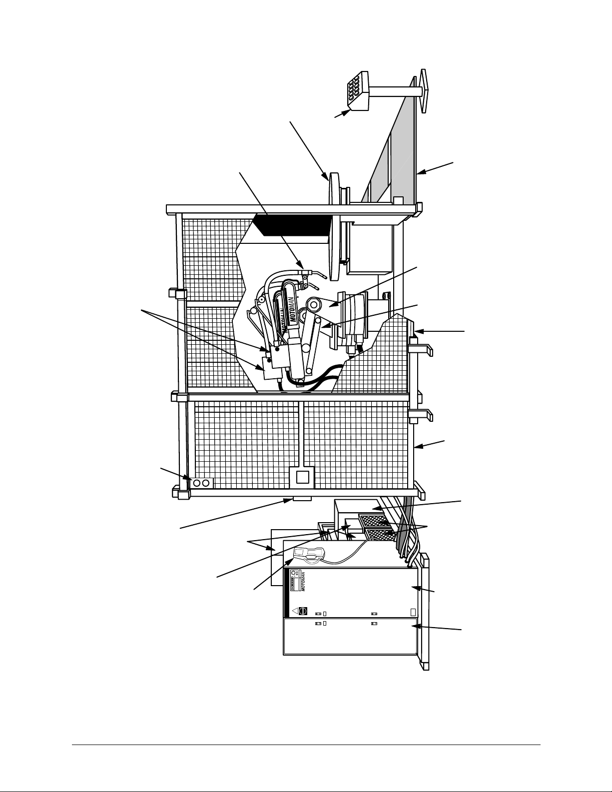
1.2.1 System Layout
The illustration in Figure 1-1 shows the system layout for the ArcWorld 1200 cell.
The ArcWorld 1200 includes the following major components:
• Motoman robot manipulators and MRC controller
• MR series indexing rotary positioner
• Operator station
• Welding equipment, including the following:
• Excel-Arc welding power source
• Torch (water-cooled or air-cooled)
• Wire feeder
• Welding interface
• Torch breakaway
• Safety equipment, including the following:
• Safety fencing with arc curtains
• Interlocked safety mats
• Interlocked cell door
• Positioner arc screen
The robot manipulators and positioner share a common base for ease of installation
and to help maintain proper alignment between these components. The MRC
controller and welding power sources also share a common base. The robotic cell
is fully enclosed by safety fencing and an interlocking door. Safety mats prevent
positioner cycling while anyone stands in front of the positioner. All operator
controls, including those on the MRC and welding power supply, are accessible
from outside of the robotic enclosure.
1.2.2 Optional Equipment
The following optional equipment is available for use with the ArcWorld 1200:
• Torch tender
• Wire cutter
• Com-Arc III
• Heavy duty positioner
• Stationary tables
Page 13

ArcWorld 1200 MRC Operator's Manual Page 5 MOTOMAN
1.3 REFERENCE TO OTHER DOCUMENTATION
For additional information refer to the following:
• Motoman K10 MRC Manipulator Manual (Part Number 132330-7)
• Motoman K6 MRC Manipulator Manual (Part Number 132330-4)
• Motoman MRC Operator's Manual for Arc Welding (Part Number 132332-1)
• Motoman MRC User Functions Manual (Part Number 132331-1)
• Motoman ArcWorld 1200 Installation Manual (Part Number 132341-2)
• Additional vendors' manuals
1.4 CUSTOMER SERVICE INFORMATION
If you are in need of technical assistance, contact the Motoman service staff at
(513) 847-3200. Have the following information ready before you call:
• Robot Type (K3, K6, K10, etc.)
• Robot Serial Number (located on the back side of the robot arm)
• Application Type (palletizing, welding, handling, etc.)
• Robot Sales Order Number (located on back side of robot and MRC controller)
Page 14

ArcWorld 1200 MRC Operator's Manual Page 6 MOTOMAN
2.0 SAFETY
It is the purchaser's responsibility to ensure that all local, county, state, and national
codes, regulations, rules, or laws relating to safety and safe operating conditions for
each installation are met and followed.
We suggest that you obtain and review a copy of the ANSI/RIA National Safety
Standard for Industrial Robots and Robot Systems. This information can be
obtained from the Robotic Industries Association by requesting ANSI/RIA
R15.06. The address is as follows:
Robotic Industries Association
900 Victors Way
P.O. Box 3724
Ann Arbor, Michigan 48106
TEL: 313/994-6088
FAX: 313/994-3338
Ultimately, the best safeguard is trained personnel. The user is responsible for
providing personnel who are adequately trained to operate, program, and maintain
the robot cell. The robot must not be operated by personnel who have not
been trained!
We recommend that all personnel who intend to operate, program, repair, or use
the robot system be trained in an approved Motoman training course and become
familiar with the proper operation of the system.
This safety section addresses the following:
• Standard Conventions (see Section 2.1)
• General Cautions and Warnings (see Section 2.2)
• Mechanical Safety Devices (see Section 2.3)
• Installation Safety (see Section 2.4)
• Programming Safety (see Section 2.5)
• Operation Safety (see Section 2.6)
• Maintenance Safety (see Section 2.7)
Page 15

ArcWorld 1200 MRC Operator's Manual Page 7 MOTOMAN
2.1 STANDARD CONVENTIONS
This manual includes information essential to the safety of personnel and
equipment. As you read through this manual, be alert to the four signal words:
• DANGER
• WARNING
• CAUTION
• NOTE
Pay particular attention to the information provided under these headings which are
defined below (in descending order of severity).
➪
DANGER!
Information appearing under the DANGER caption concerns the
protection of personnel from the immediate and imminent
hazards that, if not avoided, will result in immediate, serious
personal injury or loss of life in addition to equipment damage.
➪
WARNING!
Information appearing under the WARNING caption concerns the
protection of personnel and equipment from potential hazards
that can result in personal injury or loss of life in addition to
equipment damage.
➪
CAUTION!
Information appearing under the CAUTION caption concerns the
protection of equipment, software, and data from hazards that
can result in minor personal injury or equipment damage.
NOTE: Information appearing in a NOTE caption provides additional information which is helpful in
understanding the item being explained.
Page 16

ArcWorld 1200 MRC Operator's Manual Page 8 MOTOMAN
2.2 GENERAL SAFEGUARDING TIPS
All operators, programmers, plant and tooling engineers, maintenance
personnel, supervisors, and anyone working near the robot must become
familiar with the operation of this equipment. All personnel involved with the
operation of the equipment must understand potential dangers of operation.
General safeguarding tips are as follows:
• Improper operation can damage the equipment. Only trained personnel familiar
with the operation of this robot, the operator's manuals, the system equipment,
and options and accessories should be permitted to operate this robot system.
• Do not enter the robot cell while it is in operation. Place the robot in
Emergency Stop (E-Stop) mode and ensure that all motion has stopped before
entering the cell.
• Improper connections can damage the robot. All connections must be made
within the standard voltage and current ratings of the robot I/O (Inputs and
Outputs).
• The robot must be placed in Emergency Stop (E-Stop) mode whenever it is not
in use.
2.3 MECHANICAL SAFETY DEVICES
The safe operation of the robot, positioner, auxiliary equipment, and system is
ultimately the user's responsibility. The conditions under which the equipment will
be operated safely should be reviewed by the user. The user must be aware of the
various national codes, RIA safety recommendations, and other local codes that
may pertain to the installation and use of industrial equipment. Additional safety
measures for personnel and equipment may be required depending on system
installation, operation, and/or location. The following safety measures are available:
• Safety fences and barriers
• Light curtains
• Door interlocks
• Safety mats
• Floor markings
• Warning lights
Check all safety equipment frequently for proper operation. Repair or replace any
non-functioning safety equipment immediately.
Page 17

ArcWorld 1200 MRC Operator's Manual Page 9 MOTOMAN
2.4 INSTALLATION SAFETY
Safe installation is essential for protection of people and equipment. The user must
be aware of the various national codes, RIA safety recommendations, and other
local codes that may pertain to the installation and use of industrial equipment.
Additional safety measures for personnel and equipment may be required
depending on system installation, operation, and/or location. The following
suggestions are intended to supplement, but not replace, existing federal, local, and
state laws and regulations.
• Ensure that only trained personnel familiar with the operation of this robot, the
operator's manuals, the system equipment, and options and accessories are
permitted to operate this robot system.
• Identify the work envelope of each robot with floor markings, signs, and
barriers.
• Position all controllers outside the robot work envelope.
• Whenever possible, install safety fences to protect against unauthorized entry
into the work envelope.
• Eliminate areas where personnel might get trapped between a moving robot and
other equipment (pinch points).
• Provide sufficient room inside the workcell to permit safe teaching and
maintenance procedures.
2.5 PROGRAMMING SAFETY
All operators, programmers, plant and tooling engineers, maintenance personnel,
supervisors, and anyone working near the robot must become familiar with the
operation of this equipment. All personnel involved with the operation of the
equipment must understand potential dangers of operation. General safeguarding
tips are as follows:
• Any modifications to PART 1 of the controller PLC can cause severe personal
injury or death, as well as damage to the robot! Do not make any modifications
to PART 1. Making any changes without the written permission of Motoman
will VOID YOUR WARRANTY!
• Some operations require standard passwords and some require special
passwords. Special passwords are for Motoman use only. YOUR
WARRANTY WILL BE VOID if you use these special passwords.
• Back up all programs and jobs onto a floppy disk whenever program changes
are made. To avoid loss of information, programs, or jobs, a backup must
always be made before any service procedures are done and before any changes
are made to options, accessories, or equipment.
• The concurrent I/O (Input and Output) function allows the customer to modify
the internal ladder inputs and outputs for maximum robot performance. Great
Page 18

ArcWorld 1200 MRC Operator's Manual Page 10 MOTOMAN
care must be taken when making these modifications. Double-check all
modifications under every mode of robot operation to ensure that you have not
created hazards or dangerous situations that may damage the robot or other
parts of the system.
• Improper operation can damage the equipment. Only trained personnel familiar
with the operation, manuals, electrical design, and equipment interconnections
of this robot should be permitted to operate the system.
• Inspect the robot and work envelope to ensure no potentially hazardous
conditions exist. Be sure the area is clean and free of water, oil, debris, etc.
• Ensure that all safeguards are in place.
• Check the E-STOP button on the teach pendant for proper operation before
programming.
• Keep the teach pendant with you when you enter the workcell.
• Ensure that only the person holding the teach pendant enters the workcell.
• Test any new or modified program at low speed for at least one full cycle.
2.6 OPERATION SAFETY
All operators, programmers, plant and tooling engineers, maintenance personnel,
supervisors, and anyone working near the robot must become familiar with the
operation of this equipment. All personnel involved with the operation of the
equipment must understand potential dangers of operation. General safeguarding
tips are as follows:
• Check all safety equipment for proper operation. Repair or replace any nonfunctioning safety equipment immediately.
• Inspect the robot and work envelope to ensure no potentially hazardous
conditions exist. Be sure the area is clean and free of water, oil, debris, etc.
• Ensure that all safeguards are in place.
• Improper operation can damage the equipment. Only trained personnel familiar
with the operation, manuals, electrical design, and equipment interconnections
of this robot should be permitted to operate the system.
• Do not enter the robot cell while it is in operation. Place the robot in
Emergency Stop (E-Stop) mode and ensure that all motion has stopped before
entering the cell.
• The robot must be placed in Emergency Stop (E-Stop) mode whenever it is not
in use.
• This equipment has multiple sources of electrical supply. Electrical
interconnections are made between the controller, external servo box, and other
equipment. Disconnect and lockout/tagout all electrical circuits before making
any modifications or connections.
• All modifications made to the controller will change the way the robot operates
and can cause severe personal injury or death, as well as damage the robot.
Page 19

ArcWorld 1200 MRC Operator's Manual Page 11 MOTOMAN
This includes controller parameters; ladder nodes, parts 1 and 2; and I/O (Input
and Output) modifications. Check and test all changes at slow speed.
Page 20

ArcWorld 1200 MRC Operator's Manual Page 12 MOTOMAN
2.7 MAINTENANCE SAFETY
All operators, programmers, plant and tooling engineers, maintenance personnel,
supervisors, and anyone working near the robot must become familiar with the
operation of this equipment. All personnel involved with the operation of the
equipment must understand potential dangers of operation. General safeguarding
tips are as follows:
• Do not perform any maintenance procedures before reading and understanding
the proper procedures in the appropriate manual.
• Check all safety equipment for proper operation. Repair or replace any nonfunctioning safety equipment immediately.
• Improper operation can damage the equipment. Only trained personnel familiar
with the operation, manuals, electrical design, and equipment interconnections
of this robot should be permitted to operate the system.
• Back up all your programs and jobs onto a floppy disk whenever program
changes are made. A backup must always be made before any servicing or
changes are made to options, accessories, or equipment to avoid loss of
information, programs, or jobs.
• Do not enter the robot cell while it is in operation. Place the robot in
Emergency Stop (E-Stop) mode and ensure that all motion has stopped before
entering the cell.
• The robot must be placed in Emergency Stop (E-Stop) mode whenever it is not
in use.
• Ensure all safeguards are in place.
• Use proper replacement parts.
• This equipment has multiple sources of electrical supply. Electrical
interconnections are made between the controller, external servo box, and other
equipment. Disconnect and lockout/tagout all electrical circuits before making
any modifications or connections.
• All modifications made to the controller will change the way the robot operates
and can cause severe personal injury or death, as well as damage the robot.
This includes controller parameters; ladder nodes, parts 1 and 2; and I/O (Input
and Output) modifications. Check and test all changes at slow speed.
• Improper connections can damage the robot. All connections must be made
within the standard voltage and current ratings of the robot I/O (Inputs and
Outputs).
Page 21

ArcWorld 1200 MRC Operator's Manual Page 13 MOTOMAN
3.0 DESCRIPTION OF EQUIPMENT
3.1 K-SERIES ROBOT DESCRIPTION
The standard ArcWorld 1200 uses either two Motoman K6 or two K10 robot
manipulators. The Motoman K6 and K10 robots and YASNAC MRC Controller
represent state-of-the-art technology in robotics today. The six-axis K6 robot has a
payload of 6 kg (13.2 lbs). It features a 1,322 mm (52.01 in) reach and has a
relative positioning accuracy of ± 0.1 mm (0.004 in.). The six-axis K10 robot has
a payload of 10 kg (22 lbs). It features a 1,555 mm (61.2 in) reach and has a
relative positioning accuracy of ± 0.1 mm (0.004 in.).
Each robot can reach below its own base as well as behind itself. These robots can
also be mounted in floor, wall, or ceiling configurations with few hardware
modifications. The Motoman K-Series robots have been constructed for ease of
maintenance, utilizing brushless AC servo motors with absolute positioning
encoders. All motors are readily accessible. A combination of capacitance and
lithium batteries in both the robot encoder assemblies and in the Motoman
YASNAC MRC controller protects program position data for up to one year. The
replacement life for the lithium battery is approximately three years.
3.2 MRC CONTROLLER
The MRC controller (Figure 3-1) coordinates the operation of the ArcWorld
system. It provides the following control functions:
• User interface
• Main logic functions
• Input / output control
• Servo control
• Numeric processing
• Variable data memory
• Program and constant data memory
• Analog welding command functions
• Welding interface
• Power distribution
The MRC controls the movement of the manipulator, processes input and output
signals, controls the operation of the welding power supply, and provides the
signals to operate the welding system. It maintains variable data and performs the
numeric processing to convert to and from different coordinate systems.
Page 22

ArcWorld 1200 MRC Operator's Manual Page 14 MOTOMAN
Figure 3-1 MRC Controller
The playback box (Figure 3-2) on the MRC has the primary system controls. The
following paragraphs describe the MRC controls.
Figure 3-2 MRC Playback Box
3.2.1 Servo Power
The SERVO POWER pushbutton switch turns on the robot servo power. An
indicator lamp in the switch lights when servo power is on.
Page 23

ArcWorld 1200 MRC Operator's Manual Page 15 MOTOMAN
3.2.2 Mode Select
The Mode Select pushbutton switches (PLAY, TEACH and REMOTE) set the
robot's mode of operation. Indicator lamps in the Mode Select switches light to
show the current mode of operation. Refer to your MRC Operator's Manual for
more information.
3.2.3 Cycle Select
The Cycle Select pushbutton switches (AUTO, 1-CYCLE, and STEP) set the
operating method for playback operations. Indicator lamps in the Cycle Select
switches light to show the selected playback method. Refer to your MRC
Operator's Manual for more information.
3.2.4 Emergency Stop
The E. STOP button is connected to the system emergency stop circuit.
Interrupting the E-Stop circuit causes the robot to go into the E-Stop condition.
Pressing the E. STOP pushbutton immediately turns off servo power.
3.2.5 Alarm / Error
The ALARM / ERROR indicator lights whenever an alarm or error condition
occurs. After you reset the alarm or error condition, the indicator lamp goes off.
3.2.6 Hold
The HOLD button is a normally closed, momentarily actuated switch. Pressing the
HOLD button stops the operation of the manipulator. The Hold state is active only
while the switch is held down. The indicator lamp lights whenever the robot is in a
Hold state. Refer to your MRC Operator's Manual for more information.
3.2.7 Start
Pressing the START button causes the manipulator playback operation to start.
The indicator lamp lights during playback.
3.2.8 Playback Box Sub-Panel
The playback box has an inside sub-panel that contains additional user controls.
Refer to your MRC Operator's Manual for more information.
Page 24
ArcWorld 1200 MRC Operator's Manual Page 16 MOTOMAN
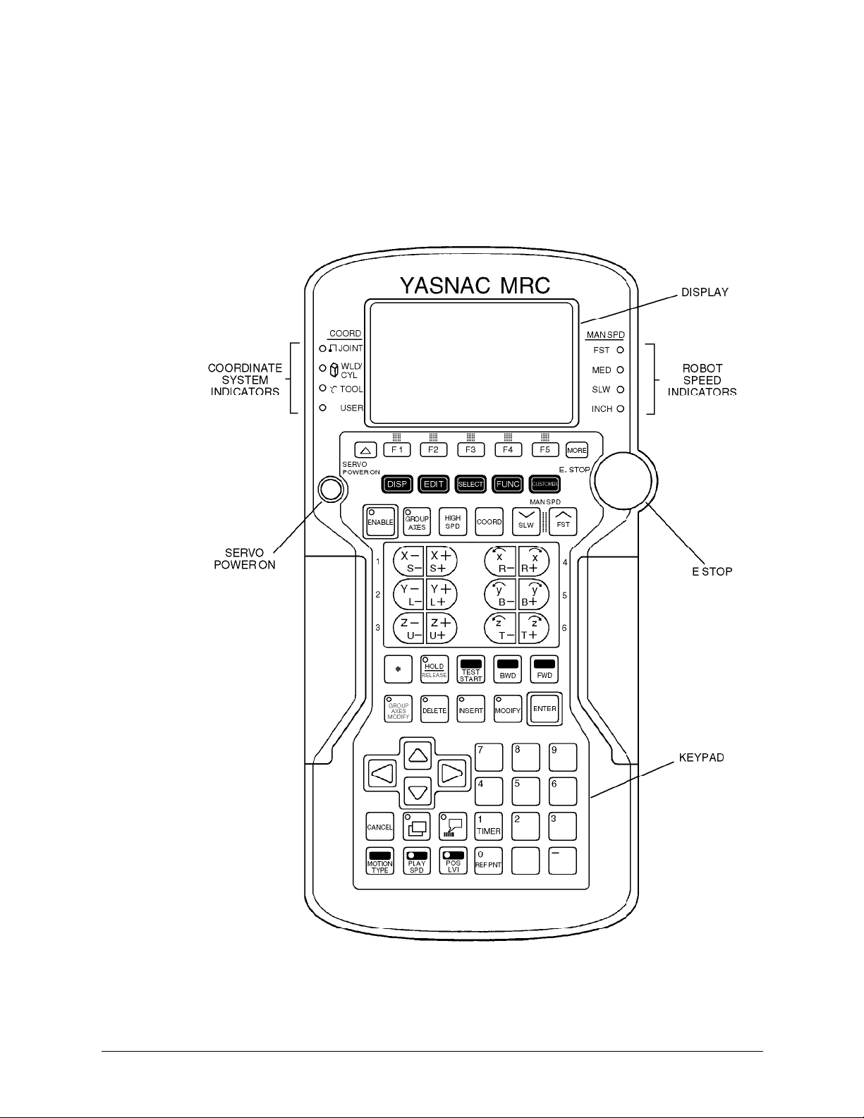
3.3 PROGRAMMING PENDANT
A programming pendant (Figure 3-3) provides the primary user interface with the
system. The pendant has a 12-line LCD display and keypad. The system uses the
INFORM II robot language and a menu driven interface to simplify operator
interaction with the robot. By using the pendant, the operator can teach robot
motion, and perform programming, editing, maintenance, and diagnostic functions.
Figure 3-3 Programming Pendant
Page 25

ArcWorld 1200 MRC Operator's Manual Page 17 MOTOMAN
3.3.1 Display
The programming pendant has a 12-line LCD display. The display provides status
information, system messages and prompts, and a graphic work area. Refer to
your MRC Operator's Manual for more information.
3.3.2 Robot Speed Indicators
The MAN SPD indicators light to show the selected robot manipulator speed.
3.3.3 Emergency Stop
The E. STOP button is connected to the system emergency stop circuit.
Interrupting the E-Stop circuit causes the robot to go into the E-Stop condition.
Pressing the E. STOP pushbutton immediately turns off servo power.
3.3.4 Keypad
The user keypad on the programming pendant serves as an input device. The keys
are grouped into different functional sections to simplify operator use. For more
information, refer to your MRC Operator's Manual.
3.3.5 Servo Power
The SERVO POWER pushbutton switch turns on the robot servo power. An
indicator lamp in the switch lights when servo power is on.
3.3.6 Coordinate System Indicators
The COORD indicators light to show the currently active coordinate system.
3.4 POSITIONER
The MR-500 is a DC motor-driven, turntable positioner. A steel arc screen divides
the standard 60-inch diameter table in half, providing two work stations. The rotary
table sweeps back and forth between two positions; one located inside the robot
cell, the other outside. Hard stops and shock absorbers built into the positioner
ensure accurate and repeatable parts positioning.
3.4.1 Part / Fixture Rating
This is the combined weight of part and fixture - 500 pounds on each side of the
Motoman MR-500 Positioner.
Page 26

ArcWorld 1200 MRC Operator's Manual Page 18 MOTOMAN
3.4.2 Part Center of Gravity
The Motoman MR-500 Positioner is rated for a maximum load with a center of
gravity of 500 pounds located 10 inches above the table tooling plate surface at a
radius of 20 inches.
3.4.3 Temperature Operating Range
40 - 110˚ Fahrenheit.
3.4.4 Humidity
Non-condensing 10 - 90% relative humidity.
NOTE: In high humidity areas, the table tooling plate may rust or corrode. Surface protection should
be used.
3.4.5 Shock
Less than 0.5 G.
3.4.6 Sweep Speed
Typically 5 seconds.
3.4.7 Electrical Requirements
All electrical power required to operate the Motoman MR-500 is supplied from the
MRC controller and consists of a 115 VAC / 60 Hz / Single-Phase circuit to
provide power for the drive system and interface.
3.4.8 Welding Current Rating
The Motoman MR-500 Positioner has a welding current capacity of 600 amperes at
100% duty cycle. The welding ground system consists of a spring loaded copper
brush that contacts a large ring mounted below the surface of the table. The ground
cable to the welding power source is connected to the insulated ground lug located
on the lower right side of the positioner base when facing the front of the ArcWorld
1200 cell.
NOTE: The ground cable connection to the insulated stud must be tight. If the connection is loose,
arcing can occur and cause the insulator to melt.
Page 27

ArcWorld 1200 MRC Operator's Manual Page 19 MOTOMAN
3.4.9 Hard Stops and Shock Absorbers
The Motoman MR-500 positioner is equipped with two hard stops and two shock
absorbers. The hard stops and shock absorbers are located on the right side of the
positioner base beneath the table top. The hard stops and the shock absorbers are
adjustable for Side A and Side B.
3.4.10 Arc Shield
The Motoman MR-500 positioner is provided with a sheet metal screen for arc
radiation protection between the operator loading zone and the welding zone. Do
not operate this equipment unless the arc shield is in place.
3.5 OP-STATION
The operator control station (Figure 3-4) includes a NEMA enclosure on a standalone pedestal. The following paragraphs describe each of the Op-station controls.
ALARM
RESET
ROBOT HOLD
MASTER JOB
START
MOTOMAN
STATION READY
POSITIONER
AUTO/MAN
SERVO ON
ESTOP
OPERATOR STATION
ENABLE/DISABLE
WARNING!
CYCLE START
CYCLE START
Figure 3-4 Operator Control Panel (Op-Station)
3.5.1 Emergency Stop
The operator station E-STOP, the robot E-STOP, the sliding door interlocks, and
the ArcWorld 1200 safety mats are connected in series in the Emergency Stop
circuit. If the E-Stop circuit is interrupted, the robot and the Motoman MR-500
positioner will go into the E-Stop condition. The operator station E-STOP light
Page 28

ArcWorld 1200 MRC Operator's Manual Page 20 MOTOMAN
will come on when the E-STOP button is pressed. In the E-Stop condition, power
to the Motoman MR-500 positioner interface is removed. This stops the table
sweep.
3.5.2 Hold
The operator station HOLD button is a normally closed pushbutton and is
connected to the MRC to cause the robots to go into the Hold condition when the
button is pressed.
3.5.3 Cycle Start
The palm buttons in the operator station use an anti tie-down technique for robot
input. The anti tie-down timer is set for 10 seconds. Holding the palm buttons
down for more than 10 seconds, causes the timer to time out and prevents the input
from reaching the robot. The CYCLE START buttons are connected to robot Input
#1.
3.5.4 Station Ready
The STATION READY lamp is interlocked with the robot CUBE #1 output. The
robots' Output #1 in conjunction with the Cube 1 relay turns on the STATION
READY lamp.
3.5.5 Alarm
The ALARM lamp is connected to the robot Alarm Occurrence output. The
ALARM lamp turns on when the robot encounters a major or minor alarm
condition.
3.5.6 Servo On
The SERVO ON pushbutton is connected to the robot Servo On input. The robot
servo motors will turn on when the SERVO ON pushbutton is pressed and an EStop condition does not exist.
3.5.7 Positioner Auto / Manual
The POSITIONER AUTO / MANUAL selector switch is used to select Automatic
or Manual Mode for the Motoman MR-500 positioner. The selector switch is
connected to robot Input #2. When the selector switch is in the Automatic position,
the robot will process the part after the positioner sweeps. In Manual Mode, the
robot will not process the part after the positioner sweeps. This function is
dependent on the structure of the master job.
Page 29

ArcWorld 1200 MRC Operator's Manual Page 21 MOTOMAN
3.5.8 Master Job Start
The MASTER JOB START pushbutton is connected to the robot external start
input. The robot will start the current active job when pressed if the robot is in Play
Mode and the servo motors are on.
3.5.9 Operator Station Enable / Disable
The OPERATOR STATION ENABLE / DISABLE selector switch is used to
transfer primary control of the ArcWorld cell from the MRC to the Op-Station.
The REMOTE MODE button on the MRC playback box lights when the opstation is enabled. Most programming pendant functions are disabled.
3.5.10 Reset
The RESET pushbutton is connected to the robot alarm reset input. Any alarm or
error condition will be cleared when this button is pressed. In addition, the RESET
pushbutton and the RIGHT CYCLE START pushbuttons are interlocked and,
when pressed simultaneously, enable the MR-500 positioner if the robot servo
motors are on. The positioner needs to be enabled at initial power up or emergency
stop or shock sensor condition.
NOTE: Resetting the positioner may cause some table motion. You must be careful when you reset
the positioner with the robot close to tooling. If an E-Stop occurs during programming, be sure
to reset the table before resuming programming.
3.6 WELDING POWER SOURCE
The Excel-Arc power source (Figure 3-5) is a constant voltage transformer-rectifier
type welding machine. It provides volt-current characteristic curves that are
essentially flat. This power source can be used with most MIG applications from
thin sheet metal to heavy gauge plate.
3.6.1 Main Power
The Input Power switch (7) turns on the main power to the Excel-Arc unit. The
main power must be on before any other section of the power source can operate.
The pilot light (1) illuminates when main power is on.
3.6.2 Volt / Amp Settings
The Welding Voltage / Amperes Control (2) adjusts the welding output and open
circuit voltage. The Volt / Amp Meter and Switch (3) display either DC voltage or
Page 30

ArcWorld 1200 MRC Operator's Manual Page 22 MOTOMAN
DC current depending on the position of the switch. Refer to your Excel-Arc
manual for additional information.
3.6.3 Terminal Connectors
The two terminals on the front of the Excel-Arc power source serve as connection
points for the welding leads. The Positive Terminal (4) connects positive welding
lead (to the wire feeder). The Negative Terminal (5) connects to the negative
welding lead (to the workpiece).
Page 31

ArcWorld 1200 MRC Operator's Manual Page 23 MOTOMAN
Figure 3-5 Excel-Arc Controls
3.6.4 Local / Remote Operation
The Local / Remote Output Control Selector Switch (6) sets the mode of operation
for the power source. For ArcWorld applications this switch should be set to
REMOTE. Refer to your Excel-Arc manual for additional information.
3.6.5 Feeder Control Receptacles
The Feeder Control Receptacle Panel (8) located in the back of the power source
provides connectors for use with remote voltage control applications. For
ArcWorld applications, the MRC connects to the 19-pin connector.
3.6.6 Circuit Breakers
The Excel-Arc power source uses two 10 amp circuit breakers (9 and 10). One
circuit breaker protects the 24 volt circuit, the other protects the 115 volt circuit.
3.6.7 AC Receptacles
The Excel-Arc unit has two standard 115 V AC Receptacles (11). These provide
auxiliary power at a maximum current of 10 amps. For applications using the
water-cooled torch, the water circulator plugs into one of these receptacles.
3.7 WELDING EQUIPMENT
In addition to the Excel-Arc power source, the ArcWorld 1200 system provides a
complete complement of arc welding equipment. In its standard configuration, the
ArcWorld system includes the following:
• PWF-600 wire feeder
• UWI welding interface
• Either an air cooled or water cooled MIG torch
• Torch breakaway mount
3.7.1 PWF4 Wire Feeder
The PWF4 wire feeder mounts on the robot arm. This 4-roll wire feeder provides
reliable wire feeding at rates up to 750 IPM. An integral gas valve provides fast
gas response time. The PWF4 feeder has an inch forward button to help simplify
set-up and reduce change-over time. The PWF4 wire feeder uses interchangeable
feed rolls to accommodate different types and sizes of wire.
Page 32

ArcWorld 1200 MRC Operator's Manual Page 24 MOTOMAN
3.7.2 Universal Welding Interface (UWI)
The UWI interface provides microprocessor control to the wire feeder and power
source. It scales the signals from the MRC to the appropriate levels required for
control of the welding components. It also provides isolation of the power source
analog signals.
Page 33

ArcWorld 1200 MRC Operator's Manual Page 25 MOTOMAN
3.7.3 MIG Torch
The ArcWorld 1200 uses either an air-cooled or water-cooled robotic/automatic
MIG torch. These are heavy-duty torches designed for quick replacement while
requiring minimum robot reprogramming. The MIG torch mounts on the end of
the robot wrist. For applications that use the water-cooled torch, the ArcWorld
1200 includes a suitable water circulator kit.
3.7.4 RAM Breakaway Mount
A Motoman RAM torch breakaway mount protects the robot, workpiece, fixture,
and positioner. It provides multi-directional impact detection, including Z-axis
collisions. The torch breakaway causes the robot to stop immediately upon impact.
Keyed joints assure accurate re-alignment of components.
3.8 SAFETY EQUIPMENT
The ArcWorld 1200 system incorporates a host of safety equipment. When all
standard safety precautions are taken, the safety equipment helps to ensure safe
operation of the robotic cell. The ANSI/RIA R15.06 Robot Safety Standard
stipulates the user is responsible for safeguarding.
Users are responsible for
determining whether the provided safeguards are adequate for plant
conditions. Users must also ensure that safeguards are maintained in
working order.
The ArcWorld 1200 safety features include the following:
• Arc screens
• Safety fencing
• Dual interlocking cell door
• Interlocked safety mats
• Emergency stop (E-STOP) buttons
3.8.1 Arc Screens
Two separate arc screens are used on the ArcWorld 1200. The first is a metal arc
screen on the turntable positioner. This screen blocks arc radiation and sparks from
the welding operation. The material used to cover the safety fencing of the entire
robotic cell acts as the second arc screen. This material reduces the amount of ultraviolet radiation that escapes from the robotic cell.
Page 34

ArcWorld 1200 MRC Operator's Manual Page 26 MOTOMAN
➪
WARNING!
Although this screen blocks dangerous arc radiation, you should
not look directly at the arc during operation without protective
eyewear!
3.8.2 Fencing
The safety fencing provided with the ArcWorld 1200 encloses the entire robotic
cell. It forms a physical barrier to prevent entry into the robot envelope.
3.8.3 Interlocks
Dual safety interlocks on the cell entrance door prevent entry into the cell during
Play mode. Opening the cell door with the robot in Play causes an E-Stop and
shuts down the entire system.
3.8.4 Safety Mats
The safety mat provided with the ArcWorld 1200 helps prevent serious injury to
anyone entering the turntable positioner area during the sweeping process. If a
person steps on this mat when the positioner is in motion, an E-Stop occurs
causing the entire system to shut down.
3.8.5 Emergency Stops
In addition to the interlocking devices described above, the ArcWorld 1200 has
strategically placed emergency stops (E-STOPS). These are operator actuated
devices that, when activated, immediately cause the system to shut down. The
following is a list of their locations:
• The MRC control panel has one E-STOP button.
• The MRC programming pendant has one E-STOP button.
• The turntable positioner operator station has one E-STOP button.
Page 35

ArcWorld 1200 MRC Operator's Manual Page 27 MOTOMAN
4.0 OPERATION
This section provides operation instructions for the ArcWorld 1200 system.
Operation procedures include the following:
• System start up
• Part set up
• Normal operation
• Fault recovery
• System shut down
We have included several sample programs. The listed programs demonstrate the
proper format and instruction sequences for different operations. You can use
these programs as guidelines when creating programs for your specific
applications.
4.1 OPERATION
The ArcWorld 1200 is a fully integrated robotic MIG welding cell. The robots
weld on one side of the turntable positioner while the operator loads the opposite
side with parts. Once the robots are finished with their process, they return to the
home position. The operator sweeps the turntable enabling the robots to start
welding on the next part.
The safety entrance door interlocks prevent anyone from entering the cell while the
robot is in Play mode. Stepping on the safety mat in front of the turntable
positioner during sweeping causes an E-stop.
The following is the typical sequence of operations for the ArcWorld 1200 Cell
after startup:
1. Load the fixture on the operator side of the positioner with the parts to be
welded.
2. Wait for the STATION READY indicator to light.
3. Press both CYCLE START palm buttons on the operator station. The
positioner sweeps to the other side and places the unwelded parts in the robot
work area. The robots then begin welding the unwelded parts.
4. Unload the welded parts from the fixture.
5. Repeat Steps 1 through 4.
4.1.1 Start Up
To start up the ArcWorld 1200 Cell from a Power Off condition, proceed as
follows:
Page 36

ArcWorld 1200 MRC Operator's Manual Page 28 MOTOMAN
1. Make sure that the disconnect from the transformer to the MRC is ON.
2. Turn on the two power source disconnects.
3. Set the Main Power switch on the MRC to ON.
4. Set the INPUT POWER switches on the welding power sources to ON. The
pilot lights on the power sources should glow.
5. Make sure that the enclosure door is closed, and the safety plug is connected.
6. Open the regulator valve on the welding gas supply.
7. Press the TEACH MODE button on the MRC playback box. The indicator
lamp in the switch should light.
8. Press the SERVO POWER button on the MRC playback box. The indicator
lamp in the switch should light.
9. Make sure the robots are in the starting positions (R1 in CUBE #1 and R2 in
CUBE #2).
10. Press the RESET button and the right CYCLE START button on the operator
station at the same time to initialize the positioner.
11. Call up the master job.
12. Press the PLAY MODE button on the MRC playback box, and then press the
AUTO CYCLE button. The indicator lamps in the switches should light.
13. Press the MASTER JOB START button on the operator station.
14. Wait for the STATION READY indicator to light.
The ArcWorld 1200 Cell is now ready for operation.
4.1.2 Fault Recovery
Under varying conditions an alarm or error can occur. Clearing an alarm or error
condition may require different operator intervention depending on the nature of the
alarm or error. In some cases, simply resetting the robot and restarting the
operation is sufficient. In other instances, you must first remedy the condition
causing the alarm or error. Refer to paragraph 4.2, Alarms and Errors.
4.1.3 E-STOP Recovery
An E-Stop can occur under one of the following conditions:
• Pressing the E-STOP button on the operator station, the programming pendant,
or the MRC playback box.
• Opening the sliding door on the robot enclosure or removing the safety plug
when the robot is not in Teach Mode.
• Stepping on the safety mat when the MR-500 positioner is sweeping.
• Activation of the shock sensor, indicating a robot crash.
Page 37

ArcWorld 1200 MRC Operator's Manual Page 29 MOTOMAN
To restart the ArcWorld 1200 Cell after an E-Stop condition occurs, follow the
procedure below.
Page 38

ArcWorld 1200 MRC Operator's Manual Page 30 MOTOMAN
1. To clear the E-Stop condition, do any of the following actions that apply:
• Release the E-STOP button on the operator station, the programming
pendant, or the MRC playback box.
• Close the sliding door and connect the safety plug.
• Step off the safety mat.
• Clear the Shock Sensor condition (refer to paragraph 4.1.4).
2. Press the SERVO ON button on operator station.
➪
CAUTION!
If an E-STOP condition occurs while the positioner is sweeping,
the positioner will continue the sweep when initialized.
3. Press the RESET button and the right CYCLE START button on the operator
station to initialize the system.
4. Press the MASTER JOB START button on the operator station.
The ArcWorld 1200 Cell will continue its operation.
4.1.4 Shock Sensor Recovery
The ArcWorld welding package includes a RAM breakaway torch mount. This
mount is designed to protect the torch from damage in case of a crash. A slight
deflection of the torch activates a SHOCK SENSOR error. A more severe crash
separates the torch mount from the robot arm. The SHOCK SENSOR error is
factory set to an E-Stop condition.
To override the shock sensor, do the following:
1. Disconnect the shock sensor plug from the connector at the front of the wire
feeder (see Figure 4-1).
2. Connect the shock sensor jumper (Motoman P/N 132601-1) to the connector at
the front of the wire feeder.
3. Press the RESET and right CYCLE START buttons on the operator's station at
the same time.
4. Use the programming pendant to operate the manipulator out of the impact
position.
5. Re-attach the sections of the torch breakaway mount if the impact caused them
to separate.
Page 39

ArcWorld 1200 MRC Operator's Manual Page 31 MOTOMAN
Feeder
Housing
Shock Sensor
Cord
Torch
Assembly
Breakaway
Shock
Sensor Plug
Shock Sensor
Jumper
Figure 4-1 Shock Sensor Override
To resume operation after clearing the Shock Sensor condition, proceed as follows:
1. Disconnect the shock sensor jumper from the connector at the front of the wire
feeder (see Figure 4-1).
➪
CAUTION!
You must remove the shock sensor jumper during normal
operation. Failure to do so can result in equipment damage.
2. Connect the shock sensor plug to the connector at the front of the wire feeder.
3. Close the interlocked enclosure doors.
4. Press the SERVO ON button on the MRC or programming pendant.
5. Press the RESET and right CYCLE START buttons on the operator's station at
the same time. This initializes the positioner.
Page 40

ArcWorld 1200 MRC Operator's Manual Page 32 MOTOMAN
➪
CAUTION!
You may need to move the robot to recover from a crash. To avoid
another crash, make sure that the robot has a clear path to the
next step.
6. Press the MASTER JOB START button.
4.1.5 Shut Down
To shut down the ArcWorld 1200 Cell after operation is complete, do the
following:
1. Make sure the robots are in the starting positions (R1 in CUBE #1 and R2 in
CUBE #2).
2. To turn off the robot servo motors, press the E-STOP button on either the
operator station, programming pendant, or MRC playback box.
3. Press the TEACH MODE button on the MRC playback box.
4. Set the MRC Main Power switch to the OFF position.
5. Turn off the MRC disconnect.
6. Set the INPUT POWER switch on the welding power sources to the OFF
position.
7. Turn off the two power source disconnects.
8. Close the regulator valve on the welding gas supply.
The ArcWorld 1200 Cell is now shut down.
4.2 ALARMS AND ERRORS
Alarms and errors will cause the program to stop. There are three levels of alarms
and errors: Error Messages, Minor Alarms, and Major Alarms.
For more detailed information about alarm recovery, refer to your Motoman MRC
Manipulator Manual.
4.2.1 Error Messages
These are simple errors such as pressing the START button when the robot is not
in Play mode, or enabling the programming pendant without the servo power being
live.
Errors like these are cleared by pressing the CANCEL or ENABLE button on the
programming pendant.
Page 41

ArcWorld 1200 MRC Operator's Manual Page 33 MOTOMAN
4.2.2 Minor Alarms
Minor alarms are usually programming errors. Minor alarms might occur if a
circle has been programmed with fewer than three circular points, etc.
These alarms are cleared by pressing one of the following:
• RELEASE soft key on the programming pendant
• RESET button on the operator's station
• ENABLE button on the programming pendant twice
4.2.3 Major Alarms
Major alarms are hardware failures. Major alarms might occur because of a servo
tracking error or an abnormal speed associated with crashes.
To clear these alarms, you must turn off the controller and then turn it on again.
4.3 PROGRAMMING
The robots may be programmed to execute synchronous jobs, simultaneous mirror
opposite jobs, both robots may be programmed to weld different seams on the
same part, or each robot may be programmed to execute a completely different job
at the same time.
NOTE: The ArcWorld 1200 robot S-axes are restricted by hard stops on the robot bases and internal
soft stops. Do not change.
4.3.1 Cube Assignment
The system uses the Cube #1 and Cube #2 Outputs as interlocks for sweeping.
These are software zones around the tool center points (TCP). They should be
defined with the robots clear of the positioner sweep motion. The Cube #1 and
Cube #2 Outputs can be viewed in the diagnostics under Specified Outputs.
The ArcWorld 1200 uses the Cube #3 Output as an interlock for robot motion.
This is a software zone between the robots in which it is possible for the robot
paths to intersect. However, when one robot is operating in this cube, the other is
prohibited from entry and vice versa.
NOTE: Redefinition of Cube #3 parameters will probably be required after a fixture change.
To assign the K6 or K10 robot manipulator positions to Cube #1, Cube #2, or
Cube #3, refer to your MRC User Functions and Operator's Manuals.
Do not
change cube positions unless absolutely necessary, as such changes increase
Page 42

ArcWorld 1200 MRC Operator's Manual Page 34 MOTOMAN
the possibility that the paths of the robot arms may intersect with fixtures or
each other.
NOTE: If the robot moves outside of the cube, the output is lost and the positioner will not sweep.
4.3.2 Sweeping Table to Side A
To sweep the Motoman MR-500 positioner to Side A:
1. Press the SERVO ON button on the operator station.
2. Make sure that robot R1 is in Cube #1 and robot R2 is in Cube #2.
3. Press the PLAY MODE button on the MRC playback box. The indicator lamp
in the switch should light.
4. If this is the first power up, or an E-Stop recovery, press the RESET button
and the right CYCLE START button.
5. Press the MASTER JOB START button.
6. Press the CYCLE START palm buttons.
7. The robot Output #2 must be on.
When the table sweeps into position at Side A, the positioner provides an input to
IN #3 "AT SIDE A". When this input turns on, robot Output #2 turns off.
NOTE: Before sweeping, make sure the weight of the part and fixturing on each side of the positioner
is approximately equal.
NOTE: Before sweeping at first power up, make sure the correct job has been loaded.
4.3.3 Sweeping Table to Side B
To sweep the Motoman MR-500 positioner to Side B:
1. Press the SERVO ON button on the operator station.
2. Make sure that robot R1 is in Cube #1 and robot R2 is in Cube #2.
3. Press the PLAY MODE button on the MRC playback box. The indicator lamp
in the switch should light.
4. If this is the first power up, or an E-Stop recovery, press the RESET button
and the right CYCLE START button.
5. Press the MASTER JOB START button.
6. Press the CYCLE START palm buttons.
Page 43

ArcWorld 1200 MRC Operator's Manual Page 35 MOTOMAN
7. The robot Output #3 must be on.
When the table sweeps into position at Side B, the positioner provides an input to
IN #4 "AT SIDE B". When this input turns on, robot Output #3 turns off.
4.3.4 I/O Assignment
The ArcWorld 1200 positioner and the ArcWorld operator station use the
following Motoman MRC user and dedicated inputs and outputs:
MRC User Inputs
• IN#1 Cycle Start Interlocked with CUBE #1
• IN#2 Auto/Manual Selector Switch
• IN#3 At Side A
• IN#4 At Side B
MRC User Outputs
• OUT#1 Station Ready Interlocked with CUBE #1
• OUT#2 Sweep to A Interlocked with CUBE #1 and CUBE #2
• OUT#3 Sweep to B Interlocked with CUBE #1 and CUBE #2
• OUT#4 Wire Cutter (optional)
MRC Dedicated Inputs
• External Emergency Stop
• External Servo On
• External Hold
• Anti-Tie Down
• In Cube 1
• In Cube 2
• External Start
• Alarm Reset
• Remote Mode On
MRC Dedicated Outputs
• Servo Power On
• Alarm Occurrence
Page 44

ArcWorld 1200 MRC Operator's Manual Page 36 MOTOMAN
• Teach Mode
• Cube 1
• Cube 2
4.4 SAMPLE JOBS
The following jobs are shown as examples only. Your system may have other
features and / or options requiring program changes. Double-check your system
before running these jobs. Lines that begin with an apostrophe (') are comments
added for clarification only and do not appear in the actual program listing.
Page 45

ArcWorld 1200 MRC Operator's Manual Page 37 MOTOMAN
4.4.1 Master Job (Concurrent Job)
Line Step Function
000 000 NOP
001 001 MOVJ P001 VJ=100.00
002 CALL JOB:SWEEPA IF IN#(04)=ON
003 CALL JOB:SWEEPB IF IN#(03)=ON
004 END
4.4.2 Sweep to A Job (Concurrent Job)
Line Step Function
000 000 NOP
001 PSTART JOB:HOME1 SUB1
002 PSTART JOB:HOME2 SUB2
003 PWAIT SUB1
004 PWAIT SUB2
005 DOUT OT#(01) ON
006 WAIT IN#(01)=ON
007 DOUT OT#(02) ON
008 WAIT IN#(03)=ON
009 DOUT OT#(02) OFF
010 DOUT OT#(01) OFF
011 CALL JOB:WELDA IF IN IN#(02)=ON
012 RET
013 END
Sweeps positioner to Side A, jumps to job WELDA, then returns to Master Job.
Page 46

ArcWorld 1200 MRC Operator's Manual Page 38 MOTOMAN
4.4.3 Sweep to B Job (Concurrent Job)
Line Step Function
000 000 NOP
001 PSTART JOB:HOME1 SUB1
002 PSTART JOB:HOME2 SUB2
003 PWAIT SUB1
004 PWAIT SUB2
005 DOUT OT#(01) ON
006 WAIT IN#(01)=ON
007 DOUT OT#(02) ON
008 WAIT IN#(03)=ON
009 DOUT OT#(02) OFF
010 DOUT OT#(01) OFF
011 CALL JOB:WELDB IF IN IN#(02)=ON
012 RET
013 END
Sweeps positioner to Side B, jumps to job WELDB, then returns to Master Job.
4.4.4 Master Robot WeldA Job (Concurrent Job)
Line Step Function
000 000 NOP
001 PSTART JOB:WELDA SUB1
'WeldA subroutine for robot R1
002 PSTART JOB:WELDAR2 SUB2
'WeldA subroutine for robot R2
003 PWAIT SUB1
004 PWAIT SUB2
005 RET
006 END
Page 47

ArcWorld 1200 MRC Operator's Manual Page 39 MOTOMAN
4.4.5 Master Robot WeldB Job (Concurrent Job)
Line Step Function
000 000 NOP
001 PSTART JOB:WELDB SUB1
'WeldB subroutine for robot R1
002 PSTART JOB:WELDBR2 SUB2
'WeldB subroutine for robot R2
003 PWAIT SUB1
004 PWAIT SUB2
005 RET
006 END
Page 48

ArcWorld 1200 MRC Operator's Manual Page 40 MOTOMAN
5.0 MAINTENANCE
5.1 PERIODIC MAINTENANCE
For periodic maintenance procedures and schedules for the K6 robot, the K10
robot, and the MRC controller, refer to your K6 MRC Manipulator Manual or K10
MRC Manipulator Manual.
For maintenance information regarding the welding power source, refer to your
Excel-Arc Owner's Manual.
Table 5-1 provides a list of periodic maintenance to be performed on the ArcWorld
1200 cell. Keep in mind that the maintenance intervals given serve as guidelines
only, you should adjust the frequency of maintenance to suit your specific work
conditions.
➪
CAUTION!
Use only the anti-freeze provided by Motoman. Automotive antifreeze contains stop-leak additives that will clog the small
torch water-cooling ports, and damage the gaskets in the
circulator pump.
Table 5-1 Periodic Maintenance
Frequency Component Procedure
Daily Water circulator
(water-cooled torch
application only)
Check the fluid in the water
circulator. Add fluid as required.
Use only distilled water and
approved antifreeze (Motoman part
number 131224-1).
Weekly MR-500 Brake Make sure positioner stops
properly at end of sweep. Adjust
brake per instruction label on brake
assembly if required.
Monthly MR-500 Turntable
Nylon Ground
Insulator
Check ground insulator for signs
of electrical breakdown (melting).
Replace the insulator as required.
Page 49

ArcWorld 1200 MRC Operator's Manual Page 41 MOTOMAN
Table 5-1 Periodic Maintenance (Continued)
Frequency Component Procedure
Monthly MR-500 Turntable
Welding Ground
There is an insulated lug at the base
of the positioner for a welding
ground. This lug is connected to
carbon brushes located under the
table top. Check the brushes for
proper lubrication and signs of
wear. Excessive heat buildup in
the brushes indicates uneven wear
or the lack of grease. Keep the
contact area lubricated with Burndy
Penetrox E conductive copper
lubricant (part no. PEN-E-8).
3 - 6 months MR-500 Flexible
Coupling
Make sure that the flange bolts are
tight. Torque to 40 ft-lbs
Regularly (based on
usage)
MR-500 Helical
Gear Unit
Check oil level and quality. Add
or change oil as required using
Shell Omala Oil #220 or
equivalent.
10,000 operating hrs MR-500 Helical
Gear Unit
Change oil using Shell Omala Oil
#220 or equivalent.
10,000 operating hrs Bearing on MR-500
Helical Gear Unit
Clean the bearing and then grease
with Shell Alvania Grease #R3.
5.2 MAINTENANCE PROCEDURES
The following procedures should be performed only as required. Read through the
instructions completely before performing any maintenance procedure. Be sure
that you understand the procedure, have the proper tools, and observe all applicable
safety precautions.
➪
WARNING!
Make sure that servo power is off before performing the following
procedures. Observe standard lockout/tagout practices.
Page 50

ArcWorld 1200 MRC Operator's Manual Page 42 MOTOMAN
5.2.1 MR-500 Shock Absorber
Proper adjustment of the shock absorber is important to achieve efficient operation.
All units are preset at the factory for maximum performance before shipping. If
deceleration becomes a problem, adjust the shock to achieve the desired declaration
rate:
1. Loosen the adjusting ring lock screw.
2. Turn the adjusting ring towards zero to achieve more cushioning and towards
nine to achieve less cushioning.
3. Tighten the adjusting ring lock screw.
5.2.2 MR-500 DC Motor Speed Control Unit
The DC Motor Speed Control Unit is factory set and serviceable by Motoman
ONLY! Opening the DC Motor Speed Controller will VOID YOUR
WARRANTY.
5.3 SPARE PARTS LIST
Table 5-2 Spare Parts
Description Part No.
AW1000 Safety Mat Kit 130157-2
MR-500 Positioner Table Shock Absorber 130592-3
Positioner Table Interface 2 Pole Relay, 24 VAC 130134-6
Positioner Table Interface 4 Pole Relay, 120 VAC 130134-5
5.4 FUSE AND CIRCUIT BREAKER PROTECTION
Tables 5-3 through 5-7 give the locations of fuses and circuit breakers that are
significant to the operation of the total system. In most cases, MRC spare fuses are
placed in the accessory bag with the MRC.
➪
WARNING!
Replace fuses with the same type and rating. Replacement of
fuses with higher amperage rating or lower voltage will damage
the robot controller and/or auxiliary equipment necessitating
costly replacement.
Page 51

ArcWorld 1200 MRC Operator's Manual Page 43 MOTOMAN
Abbreviations:
CB – designates circuit breaker
F, FU or 101FU – designates fuse
Table 5-3 Excel-Arc 6045 CV Fuses and Circuit Breakers
Device
Designator Rating Part Number Location Purpose
CB1 10A
115V
203627-7 Upper rear panel Protect 115V circuit
CB2 10A 24V 203627-7 Upper rear panel Protect 24V circuit
F1 .5 A W-11166-11 On contactor box Protect contactor
circuit
Table 5-4 MRC Cabinet Fuses and Circuit Breakers
Device
Designator Rating Part Number Location Purpose
CB
(1MCCB)
50 A
30 A
NF50-SS
NF30-SS
Upper left front
K10
Upper left front
K6
Main circuit breaker
for incoming 200 V
AC, 3 phase for
MRC cabinet
CB (1SV) 30 A Lower left side
of servo pack
Protects input for
servo pack 1SV for
S, L, and U axes
CB (2SV) 30 A Lower left side
of servo pack
Protects input for
servo pack 2SV for
R, B, and T axes
FU1 5 A GDL-5 MTU-01 Protects CPT10199
transformer, brake,
and fan circuits
FU2 5 A GDL-5 MTU-01 Protects CPT10199
transformer, brake,
and fan circuits
FU4 4 A GP-40 MTU-01 Protects robot brake
circuits
FU5 4 A GP-40 MTU-01 Protects robot brake
circuits
Page 52

ArcWorld 1200 MRC Operator's Manual Page 44 MOTOMAN
1FU 1 A GDL-1 Top/left/rear Protects the four fan
circuits of the MRC
2FU 1 A GDL-1 Top/left/rear Protects the control
transformer and fan
(above computer
rack) in the MRC
Table 5-4 MRC Cabinet Fuses and Circuit Breakers (Continued)
Device
Designator Rating Part Number Location Purpose
3FU 1 A GDL-1 Top/left/rear Protects the control
transformer and fan
(above computer
rack) in the MRC
4FU 1 A GDL-1 Top/left/rear Protects the 100 V
AC supply to the
AC receptacle for the
floppy disk
controller power
FU1 3 A SM1101 MBB-02 External voltage
protection - 24V
FU2 3 A SM1101 MBB-02 External voltage
protection - 24V
Table 5-5 Universal Welding Interface (UWI) Fuses and Circuit Breakers
Device
Designator Rating Part Number Location Purpose
F1 8A 250V On KXA motor
speed control
Limits damage from
shorts or component
breakdowns in DC
power supply
module
FU1 4A 250V Wickman
19374K-4A
On interface
board
Protects 115V circuit
Page 53

ArcWorld 1200 MRC Operator's Manual Page 45 MOTOMAN
FU2 .25A
125V
Wickman
19303K250A
On interface
board
Protects shock
sensor circuit
FU3 .5A 125V Wickman
19303K500A
On interface
board
Protects 24V circuit
Page 54

ArcWorld 1200 MRC Operator's Manual Page 46 MOTOMAN
Table 5-6 Com-Arc III Fuses and Circuit Breakers
Device
Designator Rating Part Number Location Purpose
Fuse 1A 250V TD-1 Front of
Com-Arc box
Protect 200V circuit
Table 5-7 MR-500 Positioner Fuses and Circuit Breakers
Device
Designator Rating Part Number Location Purpose
Fuse 30A
600V
Amptrap
ATM-30
Top of ratiotrol
under table
Protects input line to
ratiotrol
Page 55

ArcWorld 1200 MRC Operator's Manual Appx. A MOTOMAN
APPX. A RISK ASSESSMENT
Page 56

Risk Assessment Page 1 MOTOMAN
ArcWorld 1200 MRC
MOTOMAN Risk Assessment
ArcWorld 1200 System
Application: Arc Welding Robot Type: K6 or K10
Customer: Varies Plant Loc.: Varies
See cell layout
This document was prepared to explain the rationale behind the safeguarding of
MOTOMAN's ArcWorld 1200 robot cell.
It is the User's responsibility to
review this document and verify that the safeguards are adequate for their
plant conditions. This review should include the current revision of ANSI/RIA
R15.06 American National Standard for Industrial Robot Systems - Safety
Requirements. The User must also ensure that safeguards are used and maintained.
SAFEGUARDING PERSONNEL
Safeguarding Plant Personnel
• Barrier around robot work envelope.
• Interlocked gate for access to cell.
• Curtain around cell blocks ultra-violet radiation from arc.
• Serious hazards are identified by warning labels.
Safeguarding Operator
• Interlocked gates stop robot motion if opened in PLAY mode.
• Dual sensors on interlocked gate make safeguards difficult for operator to
defeat.
• Emergency Stop button on operator station.
• Two station positioner keeps operator out of robot work envelope.
• Extended length safety mats are interlocked to stop positioner motion when
activated. Requires reset at operator station to restart.
• Robot program will wait for Cycle Start buttons before sweeping positioner.
Page 57

Risk Assessment Page 2 MOTOMAN
ArcWorld 1200 MRC
• Cycle Start has dual palm buttons, anti-tie down, positioned for two hand
operation.
Safeguarding Teacher
• Interlocked gate: Active in PLAY mode; Inactive in TEACH mode.
• Clearance of 24" between robot and fencing.
• Emergency Stop button on programming pendant.
• S-axis motion restricted by hardstops.
• TEACH LOCK prevents operation from controller while programming
pendant is enabled.
• Continuous stepping is at reduced speed.
Safeguarding Maintenance Personnel
• Robot controls are outside barrier.
• Positioner controls are inside cell, but do not require robot drive power to
troubleshoot.
• Electrical energy sources equipped with lockout/tagout.
• Programming pendant displays I/O status and other diagnostic functions.
SOURCES OF HAZARDS
Unauthorized Access
• Interlocked barrier.
• Dual interlocks, difficult to defeat by operator.
Human Errors in Judgment
• Safety mat interlocked with positioner.
• Dual palm cycle start.
• Emergency Stops on operator station, robot controller, and programming
pendant.
Control Errors
• Most Safety features independent of program logic.
• Program must have instructions to wait for palm buttons to sweep.
Page 58

Risk Assessment Page 3 MOTOMAN
ArcWorld 1200 MRC
Mechanical / Electrical Failures
• Safety mat supplied with fail-safe circuit.
• Redundant door interlocks.
• Interlocks designed to fail-safe.
• Robot has sophisticated control loop designed to remove drive power in case of
positioning error.
Environmental
• Sheet metal partition and UV curtain to help prevent eye damage from ultra-
violet radiation.
• UV curtain helps contain welding sparks.
NOTE: Fume ventilation may be required depending on application and plant conditions. (To be
determined and provided by USER.)
NOTE: Care must be used when handling and securing compressed and combustible gasses. (User
supplied.)
Installation Defects
• Safeguards will place the robot in Emergency Stop unless they are correctly
connected.
• Safety fence is self supporting when fully erected (fencing should be lagged).
• Equipment is shipped on bases to ease installation and provide a secure
mounting surface (robot base needs to be leveled and lagged).
Power System Failure or
Inadvertent Power Initiation
• Easy recovery from power failure.
• Different levels of power up; primary power on, controller power on, servo
power on, and robot start. Difficult to inadvertently start.
Page 59

Risk Assessment Page 4 MOTOMAN
ArcWorld 1200 MRC
EQUIPMENT PROTECTION
Human Errors
• Torch breakaway protects robot and torch in the case of a torch crash.
• Cube #1 interlock requires the robot to be in a "safe" position before the
positioner can index.
• Cube #2 output is used as an interlock for robot motion. This is a software
zone between the robots in which it would be possible for the paths of the
robots to intersect. When one robot is operating in this cube, the other is
prohibited from entry, and vice versa.
Power Faults
• Isolation transformer and circuit breaker protect robot from power surges
(additional surge control may be required at your facility).
• Robot "remembers" its position and place in program at power down.
• Data has battery backup and can be saved on optional floppy disk drive.
WHAT-IF CONSIDERATIONS
What if personnel reach over safety mat and pinch an arm on moving parts?
Extended length mats are provided to help prevent inadvertent access to moving
parts.
What if there is a hazard not covered by a warning label?
Labels are provided on positioner, robot, power source, feeder, transformer, and
robot controller. Persons working on equipment should have adequate training to
identify hazards.
Page 60

ArcWorld 1200 MRC Operator's Manual Appx. B MOTOMAN
APPX. B SYSTEM OUTLINE
This section contains the following outline drawings:
Drawing Number Title Sheet Number
131927 Cell Layout Sheet 1 of 15
131927 Bill of Material Sheet 2 of 15
Page 61

ArcWorld 1200 MRC Operator's Manual Appx. C MOTOMAN
APPX. C ELECTRICAL DRAWINGS
This section contains the following electrical drawings:
Drawing Number Title Sheet Number
131927 Power Distribution Sheet 3 of 15
131927 MRC I/O MRY01-3 Board Sheet 4 of 15
131927 MRC I/O MEW01 Board Sheet 5 of 15
131927 MRC I/O MI004 Board Sheet 6 of 15
131927 MRC I/O MI004 Board Sheet 7 of 15
131927 Cable Layout Sheet 8 of 15
131927 Cable Charts Sheet 9 of 15
131927 Ladder Diagram Sheet 10 of 15
131927 Ladder Diagram Sheet 11 of 15
131927 Ladder Diagram Sheet 12 of 15
131927 Ladder Diagram Sheet 13 of 15
131927 Ladder Diagram Sheet 14 of 15
131927 Ladder Diagram Sheet 15 of 15
132209 PLC Controller Sheet 1 of 4
132209 PLC Controller Sheet 3 of 4
132209 PLC Controller Sheet 4 of 4
130161 Connection/Schematic Diagram Sheet 6 of 7
Page 62

ArcWorld 1200 MRC Operator's Manual Appx. D MOTOMAN
APPX. D MECHANICAL DRAWINGS
This section contains the following mechanical drawings:
Drawing Number Title Sheet Number
132349 MRC Common Base Sheet 1 of 1
131069 Positioner with Interface Sheet 1 of 1
130174 Positioner, Turntable, 180˚ Sheet 1 of 2
and Drive
130174 Positioner, Turntable, 180˚ Sheet 2 of 2
and Drive
130156 Positioner, Turntable, 180˚ Sheet 2 of 3
130156 Positioner, Turntable, 180˚ Sheet 3 of 3
130101 Common Base Sheet 1 of 1
130227 Robot Spanner Base Sheet 1 of 1
130157 Safety Mat Sheet 2
130158 Interlock, Entry Access Sheet 1 of 1
130161 Station, Operator Sheet 1 of 7
130161 Station, Operator Sheet 2 of 7
Page 63

ArcWorld 1200 MRC Operator's Manual Index 1 MOTOMAN
INDEX
A
About This Document, 1
AC Receptacles, 21
Alarm / Error, 13
Alarm, 18
Alarms and Errors, 28
Arc Screens, 22
Arc Shield, 17
C
Circuit Breakers, 21
Coordinate System Indicators, 15
Cube Assignment, 29
Customer Service Information, 4
Cycle Select, 13
Cycle Start, 18
D
Description of Equipment, 11
Display, 15
E
E-Stop Recovery, 25
Electrical Requirements, 16
Emergency Stop, 13, 15, 17
Emergency Stops, 23
Error Messages, 28
Excel-Arc Controls, 20
F
Fault Recovery, 25
Feeder Control Receptacles, 21
Fencing, 23
Page 64

ArcWorld 1200 MRC Operator's Manual Index 2 MOTOMAN
Fuse and Circuit Breaker Protection, 37
G
General Safeguarding Tips, 7
H
Hard Stops and Shock Absorbers, 17
Hold, 13, 18
Humidity, 16
I
I/O Assignment, 30
Installation Safety, 8
Interlocks, 23
Introduction, 1
K
K-Series Robot Description, 11
Keypad, 15
L
Local / Remote Operation, 20
M
Main Power, 19
Maintenance Procedures, 36
Maintenance Safety, 10
Maintenance, 35
Major Alarms, 29
Master Job (Concurrent Job), 32
Master Job Start, 18
Master Robot WeldA Job (Concurrent Job), 33
Master Robot WeldB Job (Concurrent Job), 34
Mechanical Safety Devices, 7
MIG Torch, 22
Minor Alarms, 28
Mode Select, 13
Page 65

ArcWorld 1200 MRC Operator's Manual Index 3 MOTOMAN
MR-500 DC Motor Speed Control Unit, 37
MR-500 Shock Absorber, 37
MRC Controller, 11, 12
MRC Playback Box, 12
Page 66

ArcWorld 1200 MRC Operator's Manual Index 4 MOTOMAN
O
Op-Station, 17
Operation Safety, 9
Operation, 24
Operator Control Panel (Op-Station), 17
Operator Station Enable / Disable, 19
Optional Equipment, 3
P
Part / Fixture Rating, 15
Part Center of Gravity, 16
Periodic Maintenance, 35
Playback Box Sub-Panel, 13
Positioner Auto / Manual, 18
Positioner, 15
Programming Pendant, 14
Programming Safety, 8
Programming, 29
PWF4 Wire Feeder, 21
R
RAM Breakaway Mount, 22
Reference to Other Documentation, 4
Reset, 19
Robot Speed Indicators, 15
S
Safety Equipment, 22
Safety Mats, 23
Safety, 5
Sample Jobs, 31
Servo On, 18
Servo Power, 12, 15
Shock Sensor Override, 27
Shock Sensor Recovery, 26
Shock, 16
Page 67

ArcWorld 1200 MRC Operator's Manual Index 5 MOTOMAN
Shut Down, 28
Spare Parts List, 37
Standard Conventions, 6
Start Up, 24
Start, 13
Station Ready, 18
Sweep Speed, 16
Sweep to A Job (Concurrent Job), 32
Sweep to B Job (Concurrent Job), 33
Sweeping Table to Side A, 29
Sweeping Table to Side B, 30
System Layout, 2, 3
System Overview, 1
T
Temperature Operating Range, 16
Terminal Connectors, 19
U
Universal Welding Interface (UWI), 21
V
Volt / Amp Settings, 19
W
Welding Current Rating, 16
Welding Equipment, 21
Welding Power Source, 19
 Loading...