

Motoman PX2850, PX2750 User Manual

March 15, 2002
MOTO MAN
805 Liberty Lane
West Carrollton, OH 45449
TEL: (937) 847-6200 FAX: (937) 847-6277
24-HOUR SERVICE HOTLINE: (937) 847-3200
The information contained within this document is the proprietary property of Motoman, Inc., and may
not be copied, reproduced or transmitted to other parties without the expressed written authorization of
Motoman, Inc.
©2002 by MOTO MAN
All Rights Reserved
Because we are constantly improving our products, we reserve the right to change specifications without notice.
MOTOMAN is a registered trademark of YASKAWA Electric Manufacturing.
XRC 2001 Controller
PX2850/PX2750
Manipulator Manual
Part Number 147197-1


TABLE OF CONTENTS
MOTO MAN i PX2850/PX2750 Manipulator Manual
Section
Page
1 INTRODUCTION ..........................................................................................................................1-1
2 SAFETY .......................................................................................................................................2-1
3 XRC SETUP................................................................................................................................. 3-1
4 PX2850/PX2750 INSTRUCTIONS ...............................................................................................4-1
5 XRC INSTRUCTIONS (SUPPLEMENT FOR PX -SERIES)............................................................. 5-1
6 XRC INSTRUCTIONS (NAS 2001) ...............................................................................................6-1
7 XRC INSTRUCTIONS-GENERAL (R2).......................................................................................... 7-1
8 PX2850/PX2750 ELEMENTARY DIAGRAMS............................................................................... 8-1

PX2850/PX2750 Manipulator Manual ii
MOTO MAN
NOTES

MOTO MAN 1-1 PX2850/PX2750 Manipulator Manual
SECTION 1
INTRODUCTION
The Motoman PX2850/PX2750 paint robot and XRC controller represent state-ofthe-art technology in robotics today. The Motoman PX2850/PX2750 has six
individual axes: Sweep, Lower arm, Upper arm, Rotate, Bend, and Twist.
The XRC controller coodinates the operation of the PX2850/PX2750 paint robot
with external equipment such as spray guns, conveyors, positioning tables, etc. The
XRC processes input and output signals, maintains variable data, and performs
numeric processing to convert to and from different coordinate systems.
Furthermore, it provides main logic functions, servo control, program and constant
data memory, and power distribution. Please read this manual thoroughly to
familiarize yourself with the many aspects of the PX2850/PX2750 paint robot and
XRC controller.
1.1 About this Document
This manual provides system information for PX2850/PX2750 paint robot and
XRC controller and contains the following sections:
SECTION 1 – INTRODUCTION
Provides general information about the structure of this manual, a list of reference
documents, and customer service information.
SECTION 2 – SAFETY
Provides information regarding the safe use and operation of the PX2850/PX2750
paint robot.
SECTION 3 — SET-UP MANUAL
Provides basic information about the installation, intitial operation, and
calibrationof the PX2850/PX2750 paint robot and XRC controller.
SECTION 4 — PX2850/PX2750 INSTRUCTIONS
Provides detailed information about the PX2850/PX2750 paint robot, including
installation, wiring, specifications, parts lists, and maintenance.
SECTION 5 — XRC INSTRUCTIONS - SUPPLEMENT FOR PX-SERIES
Provides detailed information about the XRC for PX-series paint robots, including
configuration, ladder descriptions, and parts replacement.
SECTION 6 — XRC INSTRUCTIONS–NORTH AMERICAN STANDARD 2001
Provides detailed information about the NAS XRC 2001 controller, including
descriptions, inspections, and parts replacement.
SECTION 7 — XRC INSTRUCTIONS - GENERAL
Provides general information about the XRC controller, including system set-up,
inspections, diagnosis, and configuration, as well as specifications, maintenance,
and alarm/error message lists.
SECTION 8 — PX2850/PX2750 ELEMENTARY DIAGRAMS
Provides detailed information about XRC wiring and system configuration with
regard to the PX2850/PX2750 paint robot.
1.2 Reference to Other Documentation
For additional information refer to the following:
• Concurrent I/O Parameters Manual (P/N 142102-1)
• Vendor manuals for system components not manufactured by Motoman.

INTRODUCTION
PX2850/PX2750 Manipulator Manual 1-2
MOTO MAN
1.3 Customer Service Information
If you are in need of technical assistance, contact the Motoman service staff at
(937) 847-3200. Please have the following information ready before you call:
• Robot Type (PX2850, etc.)
• Application Type (assembly, handling, etc.)
• Software Version (5.101A, etc.)
• Robot Serial Number (located on the back side of the robot arm)
• Robot Sales Order Number (located on back side of XRC controller)

MOTO MAN 2-1 PX2850/PX2750 Manipulator Manual
SECTION 2
SAFETY
2.1 Introduction
.
We suggest that you obtain and review a copy of the ANSI/RIA National Safety
Standard for Industrial Robots and Robot Systems. This information can be
obtained from the Robotic Industries Association by requesting ANSI/RIA
R15.06. The address is as follows:
Robotic Industries Association
900 Victors Way
P.O. Box 3724
Ann Arbor, Michigan 48106
TEL: (734) 994-6088
FAX: (734) 994-3338
Ultimately, the best safeguard is trained personnel. The user is responsible for
providing personnel who are adequately trained to operate, program, and maintain
the robot cell. The robot must not be operated by personnel who have not been
trained!
We recommend that all personnel who intend to operate, program, repair, or use
the robot system be trained in an approved Motoman training course and become
familiar with the proper operation of the system.
This safety section addresses the following:
• Standard Conventions (Section 2.2)
• General Safeguarding Tips (Section 2.3)
• Mechanical Safety Devices (Section 2.4)
• Installation Safety (Section 2.5)
• Programming Safety (Section 2.6)
• Operation Safety (Section 2.7)
• Maintenance Safety (Section 2.8)
It is the purchaser's responsibility to ensure that all local, county,
state, and national codes, regulations, rules, or laws relating to
safety and safe operating conditions for each installation are met
and followed.
SAFETY
PX2850/PX2750 Manipulator Manual 2-2
MOTO MAN
2.2 Standard Conventions
This manual includes information essential to the safety of personnel and
equipment. As you read through this manual, be alert to the four signal words:
• DANGER
• WARNING
• CAUTION
•NOTE
Pay particular attention to the information provided under these headings which
are defined below (in descending order of severity).
DANGER!
Information appearing under the DANGER caption concerns the
protection of personnel from the immediate and imminent hazards
that, if not avoided, will result in immediate, serious personal injury
or loss of life in addition to equipment damage.
WARNING!
Information appearing under the WARNING caption concerns the
protection of personnel and equipment from potential hazards that
can result in personal injury or loss of life in addition to equipment
damage.
CAUTION!
Information appearing under the CAUTION caption concerns the
protection of personnel and equipment, software, and data from
hazards that can result in minor personal injury or equipment
damage.
NOTE: Information appearing in a NOTE caption provides additional information which is helpful in
understanding the item being explained.

SAFETY
MOTO MAN 2-3 PX2850/PX2750 Manipulator Manual
2.3 General Safeguarding Tips
All operators, programmers, plant and tooling engineers, maintenance personnel,
supervisors, and anyone working near the robot must become familiar with the
operation of this equipment. All personnel involved with the operation of the
equipment must understand potential dangers of operation. General safeguarding
tips are as follows:
• Improper operation can result in personal injury and/or damage to the
equipment. Only trained personnel familiar with the operation of this robot,
the operator's manuals, the system equipment, and options and accessories
should be permitted to operate this robot system.
• Do not enter the robot cell while it is in automatic operation. Programmers
must have the teach pendant when they enter the robot cell.
• Improper connections can damage the robot. All connections must be made
within the standard voltage and current ratings of the robot I/O (Inputs and
Outputs).
• The robot must be placed in Emergency Stop (E-STOP) mode whenever it is
not in use.
• In accordance with ANSI/RIA R15.06, section 6.13.4 and 6.13.5, use
lockout/tagout procedures during equipment maintenance. Refer also to
Section 1910.147 (29CFR, Part 1910), Occupational Safety and Health
Standards for General Industry (OSHA).
2.4 Mechanical Safety Devices
The safe operation of the robot, positioner, auxiliary equipment, and system is
ultimately the user's responsibility. The conditions under which the equipment
will be operated safely should be reviewed by the user. The user must be aware of
the various national codes, ANSI/RIA R15.06 safety standards, and other local
codes that may pertain to the installation and use of industrial equipment.
Additional safety measures for personnel and equipment may be required
depending on system installation, operation, and/or location. The following safety
measures are available:
• Safety fences and barriers
• Light curtains
• Door interlocks
• Safety mats
• Floor markings
• Warning lights
Check all safety equipment frequently for proper operation. Repair or replace any
non-functioning safety equipment immediately.

SAFETY
PX2850/PX2750 Manipulator Manual 2-4
MOTO MAN
2.5 Installation Safety
Safe installation is essential for protection of people and equipment. The
following suggestions are intended to supplement, but not replace, existing federal,
local, and state laws and regulations. Additional safety measures for personnel and
equipment may be required depending on system installation, operation, and/or
location. Installation tips are as follows:
• Be sure that only qualified personnel familiar with national codes, local
codes, and ANSI/RIA R15.06 safety standards are permitted to install the
equipment.
• Identify the work envelope of each robot with floor markings, signs, and
barriers.
• Position all controllers outside the robot work envelope.
• Whenever possible, install safety fences to protect against unauthorized entry
into the work envelope.
• Eliminate areas where personnel might get trapped between a moving robot
and other equipment (pinch points).
• Provide sufficient room inside the workcell to permit safe teaching and
maintenance procedures.
2.6 Programming Safety
All operators, programmers, plant and tooling engineers, maintenance personnel,
supervisors, and anyone working near the robot must become familiar with the
operation of this equipment. All personnel involved with the operation of the
equipment must understand potential dangers of operation. Programming tips are
as follows:
• Any modifications to the controller PLC can cause severe personal injury or
death, as well as damage to the robot! Do not make any modifications to the
PLC. Making any changes without the written permission of Motoman will
VOID Y OUR WARRANTY!
• Some operations require standard passwords and some require special
passwords. Special passwords are for Motoman use only. YOUR
WARRANTY WILL BE VOID if you use these special passwords.
• Back up all programs and jobs onto a floppy disk whenever program changes
are made. To avoid loss of information, programs, or jobs, a backup must
always be made before any service procedures are done and before any
changes are made to options, accessories, or equipment.
• The concurrent I/O (Input and Output) function allows the customer to
modify the internal ladder inputs and outputs for maximum robot
performance. Great care must be taken when making these modifications.
Double-check all modifications under every mode of robot operation to
ensure that you have not created hazards or dangerous situations that may
damage the robot or other parts of the system.
• Improper operation can result in personal injury and/or damage to the
equipment. Only trained personnel familiar with the operation, manuals,
electrical design, and equipment interconnections of this robot should be
permitted to operate the system.

SAFETY
MOTO MAN 2-5 PX2850/PX2750 Manipulator Manual
• Inspect the robot and work envelope to be sure no potentially hazardous
conditions exist. Be sure the area is clean and free of water, oil, debris, etc.
• Be sure that all safeguards are in place.
• Check the E-STOP button on the teach pendant for proper operation before
programming.
• Carry the teach pendant with you when you enter the workcell.
• Be sure that only the person holding the teach pendant enters the workcell.
• Test any new or modified program at low speed for at least one full cycle.
2.7 Operation Safety
All operators, programmers, plant and tooling engineers, maintenance personnel,
supervisors, and anyone working near the robot must become familiar with the
operation of this equipment. All personnel involved with the operation of the
equipment must understand potential dangers of operation. Operation tips are as
follows:
• Be sure that only trained personnel familiar with the operation of this robot,
the operator's manuals, the system equipment, and options and accessories
are permitted to operate this robot system.
• Check all safety equipment for proper operation. Repair or replace any nonfunctioning safety equipment immediately.
• Inspect the robot and work envelope to ensure no potentially hazardous
conditions exist. Be sure the area is clean and free of water, oil, debris, etc.
• Ensure that all safeguards are in place.
• Improper operation can result in personal injury and/or damage to the
equipment. Only trained personnel familiar with the operation, manuals,
electrical design, and equipment interconnections of this robot should be
permitted to operate the system.
• Do not enter the robot cell while it is in automatic operation. Programmers
must have the teach pendant when they enter the cell.
• The robot must be placed in Emergency Stop (E-STOP) mode whenever it is
not in use.
• This equipment has multiple sources of electrical supply. Electrical
interconnections are made between the controller, external servo box, and
other equipment. Disconnect and lockout/tagout all electrical circuits before
making any modifications or connections.
• All modifications made to the controller will change the way the robot
operates and can cause severe personal injury or death, as well as damage the
robot. This includes controller parameters, and I/O (Input and Output)
modifications. Check and test all changes at slow speed.

SAFETY
PX2850/PX2750 Manipulator Manual 2-6
MOTO MAN
2.8 Maintenance Safety
All operators, programmers, plant and tooling engineers, maintenance personnel,
supervisors, and anyone working near the robot must become familiar with the
operation of this equipment. All personnel involved with the operation of the
equipment must understand potential dangers of operation. Maintenance tips are
as follows:
• Do not perform any maintenance procedures before reading and
understanding the proper procedures in the appropriate manual.
• Check all safety equipment for proper operation. Repair or replace any nonfunctioning safety equipment immediately.
• Improper operation can result in personal injury and/or damage to the
equipment. Only trained personnel familiar with the operation, manuals,
electrical design, and equipment interconnections of this robot should be
permitted to operate the system.
• Back up all your programs and jobs onto a floppy disk whenever program
changes are made. A backup must always be made before any servicing or
changes are made to options, accessories, or equipment to avoid loss of
information, programs, or jobs.
• Do not enter the robot cell while it is in automatic operation. Programmers
must have the teach pendant when they enter the cell.
• The robot must be placed in Emergency Stop (E-STOP) mode whenever it is
not in use.
• Be sure all safeguards are in place.
• Use proper replacement parts.
• This equipment has multiple sources of electrical supply. Electrical
interconnections are made between the controller, external servo box, and
other equipment. Disconnect and lockout/tagout all electrical circuits before
making any modifications or connections.
• All modifications made to the controller will change the way the robot
operates and can cause severe personal injury or death, as well as damage the
robot. This includes controller parameters and I/O (Input and Output)
modifications. Check and test all changes at slow speed.
• Improper connections can damage the robot. All connections must be made
within the standard voltage and current ratings of the robot I/O (Inputs and
Outputs).

MOTOMAN
SETUP MANUAL
Upon receipt of the product and prior to initial operation, read these instructions
thoroughly, and retain for future ref erence .
MOT OMAN INSTR UCTIONS
MOT OMAN SETUP MANU AL
MOT OMANYASNAC XRC INSTRUCTION MANUAL
YASNAC XRC OPERA TOR’S MANUAL
YASNAC XRC OPERA TOR’S MANUAL FOR BEGINNERS
MANIPULATOR INSTRUCTION MANU AL
ooo
YASKAWA
The YASNAC XRC operator’s manuals above correspond to specific usage.
Please be sure to use the appropriate manual.
YASKAWA
MANUAL NO. RE-TA-A503
1
• This manual explains the various components of the YASNAC XRC system and general operations. Read this manual carefully and be sure to
understand its contents before handling the YASNAC XRC.
• General items related to safety are listed in Section 1: Safety of the
Setup Manual. To ensure correct and safe operation, carefully read the
Setup Manual before reading this manual.
• Some drawings in this manual are shown with the protective covers or
shields removed for clarity. Be sure all covers and shields are replaced
before operating this product.
• The drawings and photos in this manual are representative examples
and differences may exist between them and the delivered product.
• Y ASKA W A may modify this model without notice when necessary due to
product improvements, modifications, or changes in specifications. If
such modification is made, the manual number will also be revised.
• If your copy of the manual is damaged or lost, contact a YASKAWA representative to order a new copy. The representatives are listed on the
back cover. Be sure to tell the repr esentative the manual number listed
on the front cover.
• YASKAWA is not responsible for incidents arising from unauthorized
modification of its products. Unauthorized modification voids your product’s warranty.
ii
NOTES FOR SAFE OPERATION
Read this manual carefully before installation, operation, maintenance, or inspection of the
YASNAC XRC.
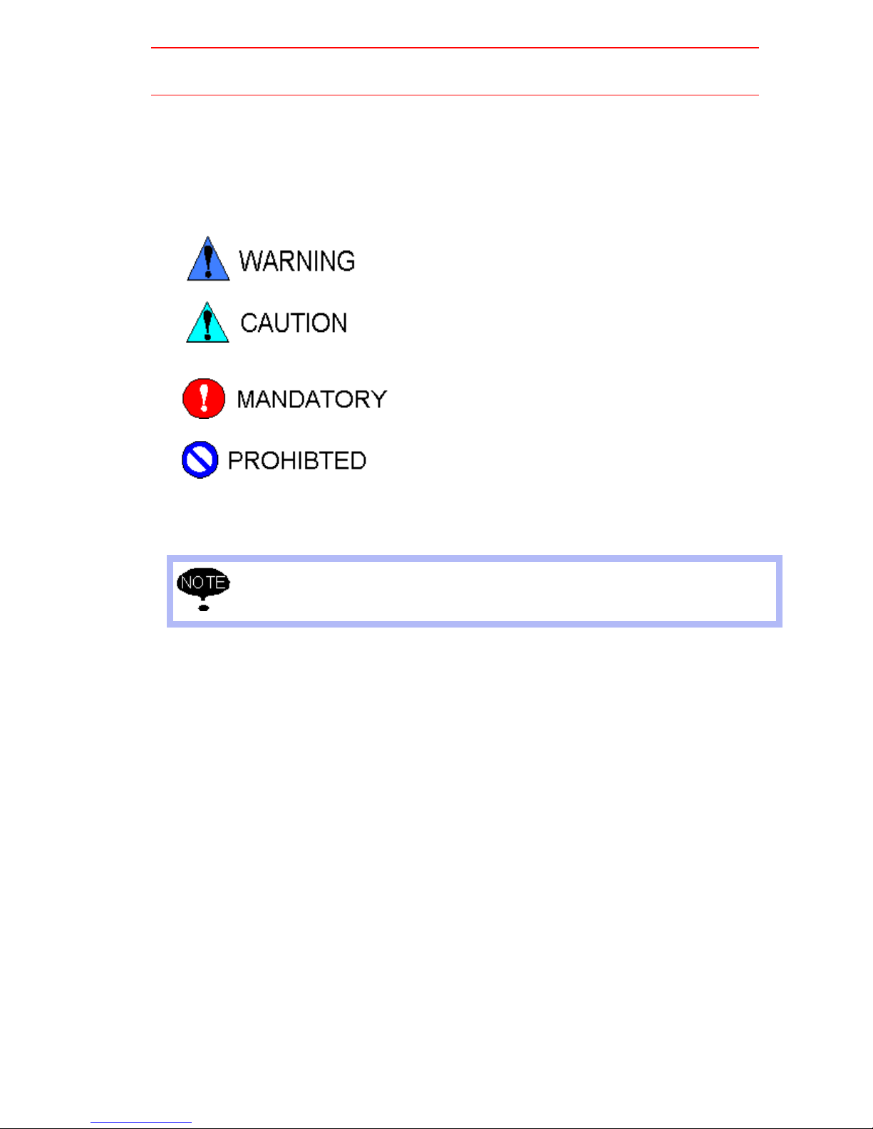
In this manual, the Notes for Saf e Oper ation are classified as “WARNING,” “CA UTION,” “MANDATORY,” or “PROHIBITED.”
Indicates a potentially hazardous situation which, if not avoided,
could result in death or serious injury to personnel.
Indicates a potentially hazardous situation which, if not avoided,
could result in minor or moderate injury to personnel and damage to equipment. It may also be used to alert against unsafe
practices.
Always be sure to follow explicitly the items listed under this
heading.
Must never be performed.
Even items described as “CAUTION” may result in a serious accident in some situations. At
any rate, be sure to follow these important items.
To ensure safe and efficient operation at all times, be sure to follow all instructions, e ven if
not designated as “CAUTION” and “WARNING.”
iii
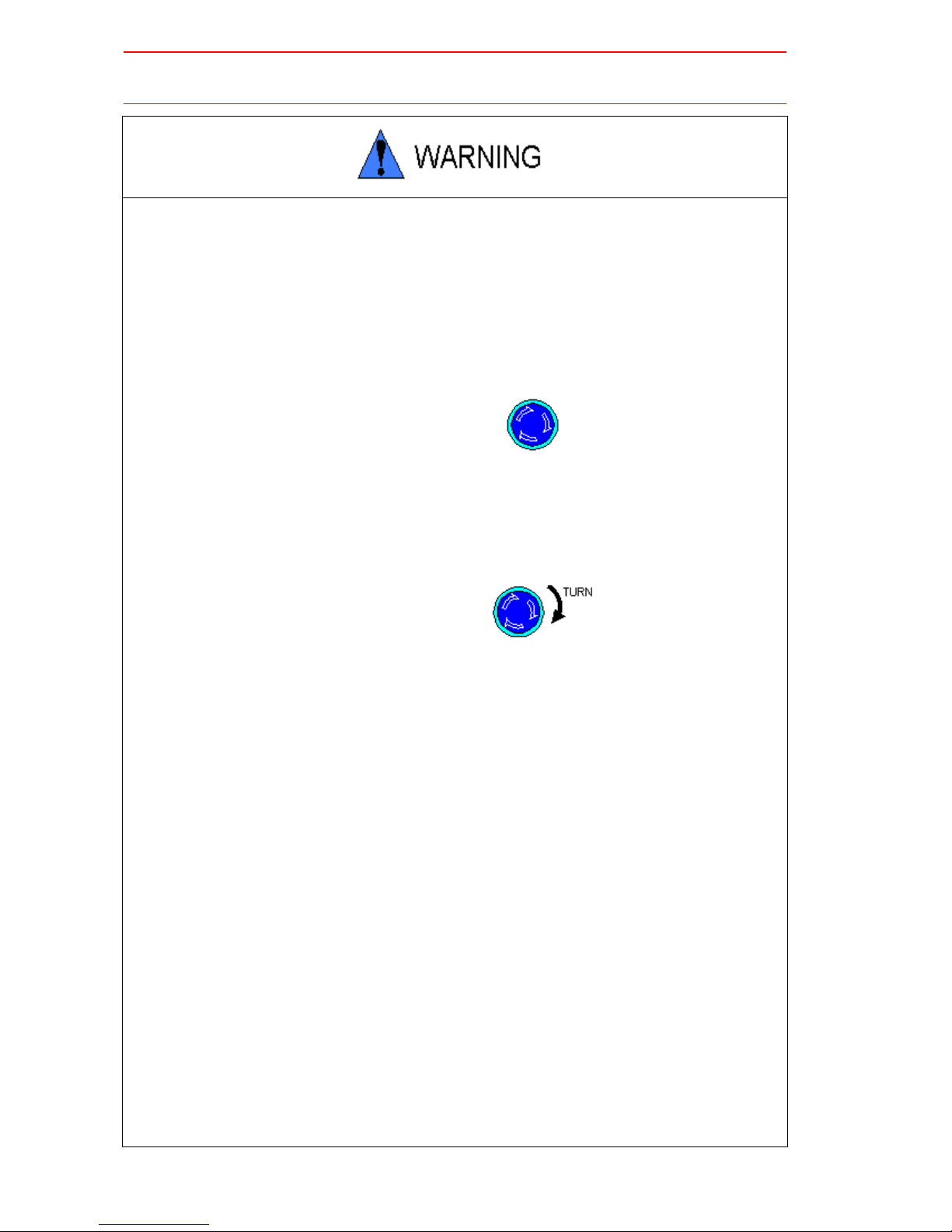
• Before operating the manipulator, check that the servo power is turned
off when the emergency stop buttons on the playback panel or programming pendant are pressed.
When the servo power is turned off, the SERVO ON READY lamp on the
playback panel and the SERVO ON LED on the programming pendant are
turned off.
Injury or damage to machinery may result if the emergency stop circuit cannot stop the
manipulator during an emergency. The manipulator should not be used if the emergency
stop buttons do not function.
Emergency Stop Button
• Once the emergency stop button is released, clear the cell of all items
which could interfere with the operation of the manipulator. Then turn
the servo power ON
Injury may result from unintentional or unexpected manipulator motion.
Release of Emergency Stop
• Always set the Teach Lock before entering the robot work envelope to
teach a job.
Operator injury can occur if the Teach Lock is not set and the manipulator is started from
the playback panel.
• Observe the following precautions when performing teaching operations
within the working envelope of the manipulator:
- View the manipulator from the front whenever possible.
- Always follow the predetermined operating procedure.
- Ensure that you have a safe place to retreat in case of emergency.
Improper or unintended manipulator operation may result in injury.
• Confirm that no persons are present in the manipulator’s work envelope
and that you are in a safe location before:
- Turning on the YASNAC XRC power
- Moving the manipulator with the programming pendant
- Running check operations
- Performing automatic operations
Injury may result if anyone enters the working envelope of the manipulator during operation. Always press an emergency stop button immediately if there are problems. The
emergency stop button is located on the right side of both the YASNAC XRC playback
panel and programming pendant.
iv
• Perform the following inspection procedures prior to conducting manipulator teaching. If problems are found, repair them immediately, and be
sure that all other necessary processing has been performed.
-Check for problems in manipulator movement.
-Check for damage to insulation and sheathing of external wires.
• Always return the programming pendant to the hook on the XRC cabinet
after use.
The programming pendant can be damaged if it is left in the manipulator’s work area, on
the floor, or near fixtures.
• Read and understand the Explanation of the Alarm Display in the Setup
Manual before operating the manipulator.
Definition of Terms Used Often in This Manual
The MOTOMAN manipulator is the YASKAWA industrial robot product.
The manipulator usually consists of the controller, the playback panel, the programming pendant, and supply cables.
In this manual, the equipment is designated as follows:
Equipment Manual Designation
Manipulator Manipulator
Power Cable Power Cable
YASNAC XRC Controller XRC
YASNAC XRC Playback Panel Playback Panel
YASNAC XRC Programming Pendant Programming Pendant
v
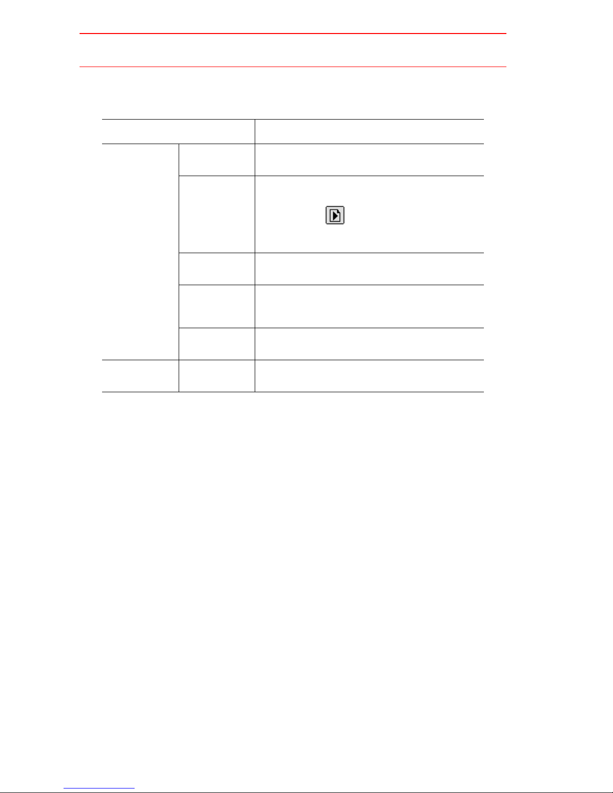
Descriptions of the programming pendant and playback panel k e ys, b uttons, and displa ys are
shown as follows:
Equipment Manual Designation
Programming
Pendant
Playback Panel Buttons Playback panel buttons are enclosed in brackets,
Character Keys The keys which hav e characters printed on them are
denoted with [ ], e.g., [ENTER].
Symbol Keys The keys which have a symbol printed on them are
not denoted with [ ] but depicted with a small picture.
e.g., page key
The cursor key is an exception, and a picture is not
shown.
Axis Keys
Number Keys
Keys pressed
simultaneously
Displays The menu displayed in the programming pendant is
“Axis Keys” and “Number Keys” are generic names
for the keys for axis operation and number input.
When two keys are to be pressed simultaneously,
the keys are shown with a “+” sign between them,
e.g., [SHIFT]+[COORD].
denoted with { }, e.g., {JOB}.
e.g., [TEACH] on the playback panel.
Description of the Operation Procedure
In the explanation of the operation procedure, the e xpression "Select • • • " means that the cursor is moved to the object item and the SELECT key is pressed.
vi
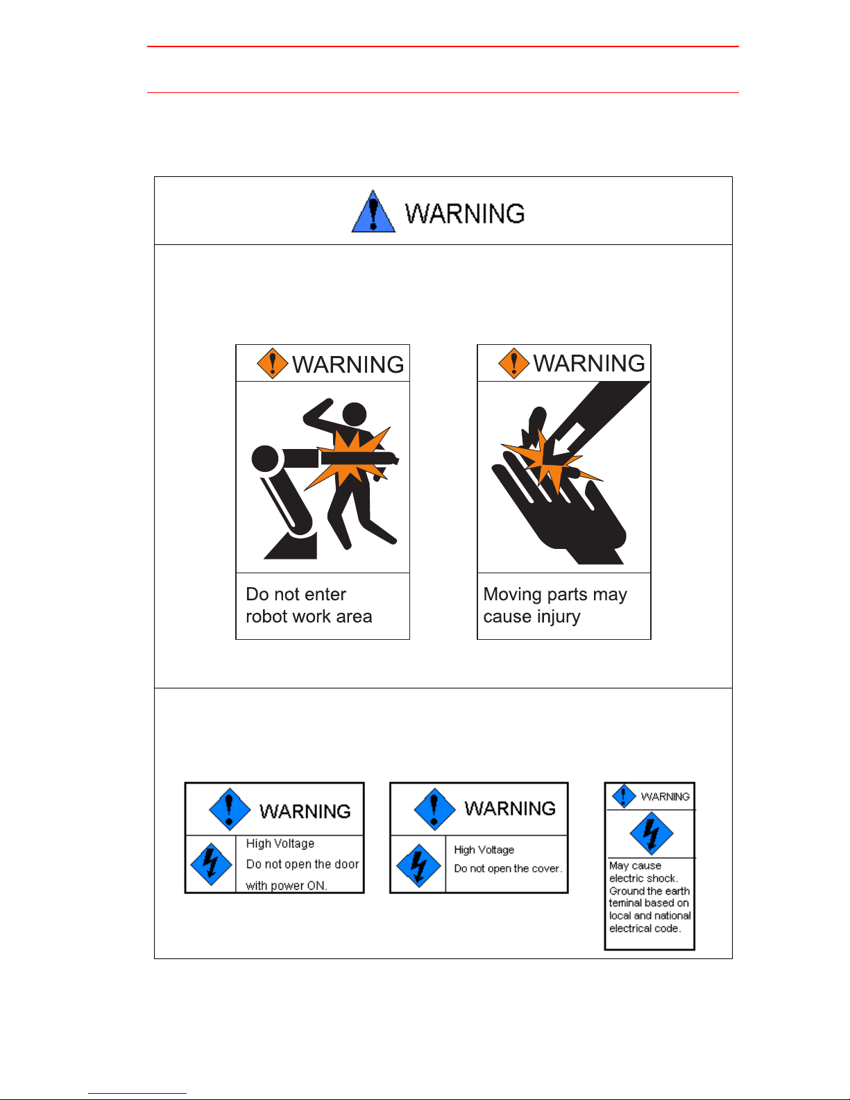
Explanation of warning labels
The following warning labels are attached to the manipulator and XRC.
Fully comply with the precautions on the warning labels.
• The label described below is attached to the manipulator.
Observe the precautions on the warning labels.
Failure to observe this caution may result in injury or damage to equipment.
Refer to the manipulator manual for the warning label location.
• The following warning labels are attached to XRC.
Fully comply with the precautions on the warning labels.
Failure to observe this warning may result in injury or damage to equipment.
vii

viii

1
Safety
1.1
1.2
For Your Safety
Special Training
. . . . . . . . . . . . . . . . . . . . . . . . . . . . . . . . . . . . . . . . . . . .1-1
. . . . . . . . . . . . . . . . . . . . . . . . . . . . . . . . . . . . . . . . . . . .1-3
1.3
Motoman Manual List
1.4
Personnel Safety
1.5
Motoman Safety
1.5.1
Installation and Wiring Safety . . . . . . . . . . . . . . . . . . . . . . . . . . . . . . .1-6
1.5.2
Work Area Safety. . . . . . . . . . . . . . . . . . . . . . . . . . . . . . . . . . . . . . . .1-10
1.5.3
Operation Safety . . . . . . . . . . . . . . . . . . . . . . . . . . . . . . . . . . . . . . . .1-11
1.6
Notes for Moving and Transferring the MOTOMAN
1.7
Notes on MOTOMAN Disposal
2
Product Confirmation
2.1
Contents Confirmation
2.2
Order Number Confirmation
3
Installation
3.1
Handling Procedure
3.1.1
Using a Crane to Move the Controller . . . . . . . . . . . . . . . . . . . . . . . . .3-1
3.1.2
Using a Forklift to Move the Controller . . . . . . . . . . . . . . . . . . . . . . . .3-2
3.2
Place of Installation
. . . . . . . . . . . . . . . . . . . . . . . . . . . . . . . . . . . . . .1-3
. . . . . . . . . . . . . . . . . . . . . . . . . . . . . . . . . . . . . . . . . . .1-4
. . . . . . . . . . . . . . . . . . . . . . . . . . . . . . . . . . . . . . . . . . . .1-6
. . . . . . . .1-14
. . . . . . . . . . . . . . . . . . . . . . . . . . . .1-15
. . . . . . . . . . . . . . . . . . . . . . . . . . . . . . . . . . . . . .2-1
. . . . . . . . . . . . . . . . . . . . . . . . . . . . . . . .2-2
. . . . . . . . . . . . . . . . . . . . . . . . . . . . . . . . . . . . . . . .3-1
. . . . . . . . . . . . . . . . . . . . . . . . . . . . . . . . . . . . . . . . .3-2
3.3
Location
3.4
Mounting the Controller
4
Connection
4.1
Notes on Cable Junctions
4.2
Power Supply
4.2.1
4.2.2
4.2.3
4.2.4
4.3
Connection Methods
4.3.1
4.3.2
4.3.3
. . . . . . . . . . . . . . . . . . . . . . . . . . . . . . . . . . . . . . . . . . . . . . . . . . . .3-3
. . . . . . . . . . . . . . . . . . . . . . . . . . . . . . . . . . . . .3-4
. . . . . . . . . . . . . . . . . . . . . . . . . . . . . . . . . .4-2
. . . . . . . . . . . . . . . . . . . . . . . . . . . . . . . . . . . . . . . . . . . . . .4-3
Three-Phase Power Supply. . . . . . . . . . . . . . . . . . . . . . . . . . . . . . . . .4-3
Noise Filter Installation . . . . . . . . . . . . . . . . . . . . . . . . . . . . . . . . . . . .4-4
Leakage Breaker Installation . . . . . . . . . . . . . . . . . . . . . . . . . . . . . . .4-4
Primary Power Supply Switch Installation . . . . . . . . . . . . . . . . . . . . . .4-5
. . . . . . . . . . . . . . . . . . . . . . . . . . . . . . . . . . . . . . .4-6
Connecting the Primary Power Supply . . . . . . . . . . . . . . . . . . . . . . . .4-6
Connecting the Power Supply . . . . . . . . . . . . . . . . . . . . . . . . . . . . . .4-9
Connecting the Programming Pendant . . . . . . . . . . . . . . . . . . . . . . .4-11
ix

5
Turning on the Power Supply
5.1
Turning on the Main Power Supply
5.1.1
Startup Diagnostics. . . . . . . . . . . . . . . . . . . . . . . . . . . . . . . . . . . . . . . 5-1
5.1.2
When Startup Diagnostics are Complete . . . . . . . . . . . . . . . . . . . . . . 5-2
5.2
Turning on the Servo Power
5.2.1
During Play Mode . . . . . . . . . . . . . . . . . . . . . . . . . . . . . . . . . . . . . . . .5-2
5.2.2
During Teach Mode . . . . . . . . . . . . . . . . . . . . . . . . . . . . . . . . . . . . . .5-3
5.3
Turning the Power Off
5.3.1
Turning the Servo Power Off (Emergency Stop) . . . . . . . . . . . . . . . .5-4
5.3.2
Turning the Main Power Off . . . . . . . . . . . . . . . . . . . . . . . . . . . . . . . .5-4
6
Test of Program Operation
6.1
Movement of the Axes
7
Home Position Confirmation
. . . . . . . . . . . . . . . . . . . . . . . . . . . . . . . . . . . . . .5-4
. . . . . . . . . . . . . . . . . . . . . . . . . . . . . . . . . . . . .6-3
. . . . . . . . . . . . . . . . . . . . . . . . .5-1
. . . . . . . . . . . . . . . . . . . . . . . . . . . . . . . .5-2
7.1
Home Position Confirmation
7.1.1
8
Final Notes
. . . . . . . . . . . . . . . . . . . . . . . . . . . . . . . .7-3
Operating Procedure. . . . . . . . . . . . . . . . . . . . . . . . . . . . . . . . . . . . . . 7-3
x

About Setup Manual Configuration
Thank you very much for purchasing Yaskawa Electric Mfg. Co., Ltd.’s manipulator .
This Setup Manual contains instructions for the safe use of the manipulator, and safe installation and wiring.
This manual is arranged as follows:
Chapter 1 includes general notes for safe and proper oper ation of the MOTOMAN.
Chapter 2 explains how to receive the manipulator and its support equipment.
Chapter 3 explains XRC installation, location, and setup.
Chapter 4 explains how to connect the primary power supply and power cables.
Chapter 5 explains how to turn the power supply on/off.
Chapter 6 explains the check operation and manipulator handling.
Chapter 7 explains home position registration and confirmation.
Chapter 8 lists all the manuals and their relevant uses.
xi

xii

1
1.1 For Your Safety
Safety
1.1
Robots generally have requirements which are different from other manufacturing equipment,
such as larger working areas, high-speed operation, rapid arm movements, etc., which can
pose safety hazards.
Read and understand the instruction manuals and related documents, and observe all precautions in order to avoid the risk of injury to personnel and damage to equipment.
It is the user’s responsibility to ensure that all local, state, and national codes, regulations
rules, or laws relating to safety and safe operating conditions are met and followed.
For Your Saf ety
1-1

1.1 For Your Safety
• Teaching maintenance of the robot must conform to:
-Industrial Safety and Health Law
-Enforcement Order of Industrial Safety and Health Law
-Ordinance of Industrial Safety and Health Law
Other related laws are:
-Occupational Safety and Health Act in USA
-Factory Act (Gewerbeordnung) in Germany
-Health and Safety at Work, etc. Act in UK
-EC Directive 89/392 Machinery and 91/368 EEC
• Prepare
-SAFETY WORK REGULATIONS
based on concrete policies for safety management complying with related laws.
• Observe the
-MANIPULATING INDUSTRIAL ROBOTS-SAFETY (ISO 10218)
for safe operation of the robot. (Japan Only) (JIS B 8433)
• Reinforce the
-SAFETY MANAGEMENT SYSTEM
by designating authorized workers and safety managers, as well as giving continuing
safety education.
• Teaching and maintaining the robot are specified as
"Hazardous Operations" in the Industrial Safety and Health Law
(Japan only).
Workers employed in these above operations are requested to attend special training
offered by YASKAWA.
1-2
1.2 Special Training
1.2
• Persons who teach or inspect the manipulator must undergo required
training before using the manipulator.
• For more information on training, inquire at the nearest YASKAWA
branch office.
The telephone numbers are listed on the back cover of this manual.
1.3
Special Training
Motoman Manual List
• It is important to have and be familiar with all manuals concerning the
MOTOMAN.
You should have the four manuals listed below:
-MOTOMAN SETUP MANUAL
-MOTOMAN-
-YASNAC XRC INSTRUCTIONS
-YASNAC XRC OPERATOR’S MANUAL FOR BEGINNERS
-YASNAC XRC OPERATOR’S MANUAL
Confirm that you have all these manuals on hand.
If any manuals are missing, contact your salesman from YASKAWA’s local branch office.
The relevant telephone numbers are listed on the back cover.
ooo
INSTRUCTIONS
1-3
1.4 Personnel Safety
1.4
The entire manipulator working envelope is potentially dangerous.
All personnel working with the MOTOMAN (safety administration, installation, operation, and
maintenance personnel) must always be prepared and "Safety First" minded, to ensure the
safety of all personnel.
• Avoid any dangerous actions in the area where the MOTOMAN is
installed.
There is a danger of injury if there is contact with the manipulator or peripheral equipment.
• Please take strict safety precautions by placing signs such as "Flammable," "High Voltage," "Waiting," and "Off-limits to Unauthorized Personnel" in necessary areas in the factory.
Failure to observe these cautions ma y result in fire, electric shock, or injury due to contact
with the manipulator and other equipment.
Personnel Safety
• Strictly observe the following items:
-Always wear approved work clothes (no loose-fitting clothes).
-Do not wear gloves when operating the MOTOMAN.
-Do not allow underwear , shirts, or neckties to hang out from the work
clothes.
-Do not wear large jewelry, such as earrings, rings, or pendants.
Always wear protective safety equipment such as helmets, safety shoes (with slip-proof
soles),face shields, safety glasses, and gloves as necessary.
Improper clothing may result in injury.
• Unauthorized persons should not approach the manipulator or associated peripheral equipment.
Failure to observe this caution may result in injury due to contact with XRC, playback
panel, the workpiece, the positioner, etc.
1-4
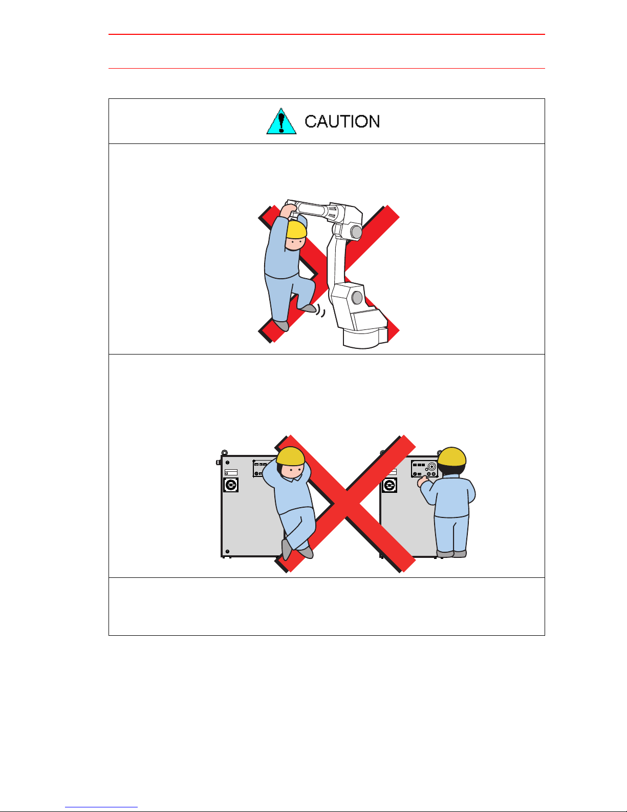
• Never forcibly move the manipulator axes.
Failure to observe this caution may result in injury or equipment damage.
1.4 Personnel Safety
• Never lean on XRC or other controllers, and avoid inadvertently pushing
buttons.
Failure to observe this caution may result in injury or damage by unexpected movement
of the manipulator.
• Never allow unauthorized personnel to touch the XRC during operation.
Failure to observe this caution may result in injury or damage resulting from unexpected
movement of the manipulator.
1-5
1.5 Motoman Safety
1.5 Motoman Safety
1.5.1
Installation and Wiring Safety
Refer to the MOTOMAN-ooo Instructions manual and XRC Instructions for details on installation and wiring.
In planning installation, adapt an easy to observe arrangement to ensure safety. Take safety
into consideration when planning the installation. Observe the following when installing the
manipulator:
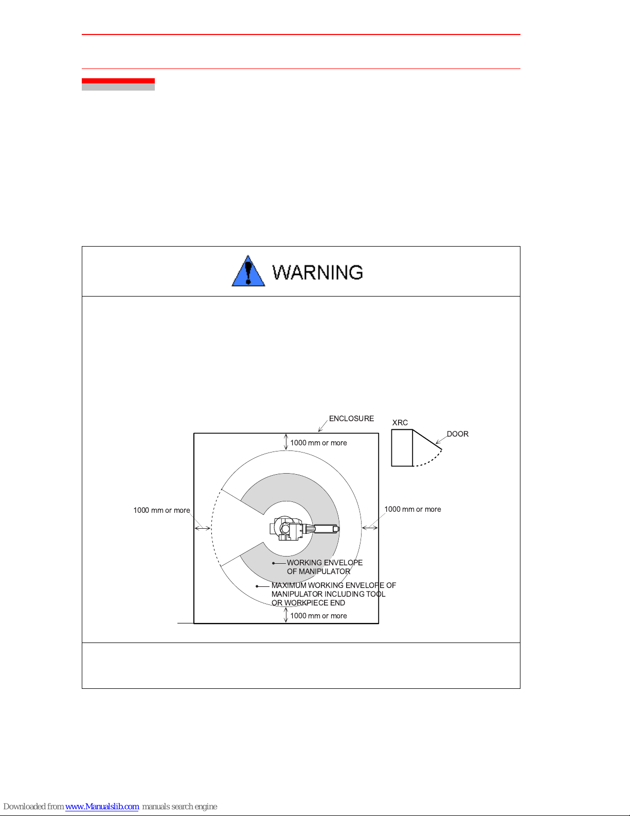
• Select an area such as that described below to install the manipulator:
Confirm that the area is large enough so that the fully extended manipulator arm with tool will not reach a side wall, safeguards, or the controller.
Failure to observe this caution may result in injury or damage resulting from unexpected
movement of the manipulator.
ENCLOSURE
1000 mm or more
XRC
DOOR
1000 mm or more
• Perform grounding in accordance with all applicable electrical codes.
Failure to observe this caution may result in fire or electric shock.
1000 mm or more
WORKING ENVELOPE
OF MANIPULATOR
MAXIMUM WORKING ENVELOPE OF
MANIPULATOR INCLUDING TOOL
OR WORKPIECE END
1000 mm or more
1-6
 Loading...