

Page 1

Motoman NX 100 Controller
Data Transmission
Function Manual
Part Number: 152388-1CD
Revision: 0
Motoman, Incorporated
805 Liberty Lane
West Carrollton, OH 45449
TEL: (937) 847-6200
FAX: (937) 847-6277
24-Hour Service Hotline: (937) 847-3200
Page 2

The information contained within this document is the proprietary property of Motoman, Inc., and may not be
copied, reproduced or transmitted to other parties without the expressed written authorization of Motoman,
©2006 by MOTOMAN
Because we are constantly improving our products, we reserve the right to change specifications without
notice. MOTOMAN is a registered trademark of YASKAWA Electric Manufacturing.
Inc.
All Rights Reserved
Page 3

Data Transmission
152388-1
Chapter 1
Introduction
1.1 About This Document
This manual provides information for the Data Transmission function and contains the following sections:
CHAPTER 1 - INTRODUCTION
Provides general information about the structure of this manual, a list of reference documents, and
customer service information.
CHAPTER 2 - SAFETY
This section provides information regarding the safe use and operation of Motoman products.
CHAPTER 3 - DATA TRANSMISSION INSTRUCTIONS
Provides detailed information for the Data Transmission function.
1.2 Reference to Other Documentation
For additional information refer to the following:
• NX100 Controller Manual (P/N 149201-1)
• Concurrent I/O Manual (P/N 149230-1)
• Operator’s Manual for your application
• Vendor manuals for system components not manufactured by Motoman
1.3 Customer Service Information
If you are in need of technical assistance, contact the Motoman service staff at (937) 847-3200. Please have
the following information ready before you call:
• Robot Type (IA20)
• Application Type (welding, handling, etc.)
• Robot Serial Number (located on back side of robot arm)
• Robot Sales Order Number (located on back of controller)
Final page 1
Page 4

Function Manual
Chapter 1 Introduction
Notes
page 2 Final
Page 5

Data Transmission
152388-1
Chapter 2
Safety
2.1 Introduction
It is the purchaser’s responsibility to ensure that all local, county, state,
and national codes, regulations, rules, or laws relating to safety and safe
operating conditions for each installation are met and followed.
We suggest that you obtain and review a copy of the ANSI/RIA National Safety Standard for
Industrial Robots and Robot Systems. This information can be obtained from the Robotic Industries
Association by requesting ANSI/RIA R15.06-1999. The address is as follows:
Robotic Industries Association
900 Victors Way
P.O. Box 3724
Ann Arbor, Michigan 48106
TEL: (734) 994-6088
FAX: (734) 994-3338
INTERNET: www.roboticsonline.com
Ultimately, the best safeguard is trained personnel. The user is responsible for providing personnel
who are adequately trained to operate, program, and maintain the robot cell. The robot must not be
operated by personnel who have not been trained!
We recommend that all personnel who intend to operate, program, repair, or use the robot system be
trained in an approved Motoman training course and become familiar with the proper operation of the
system.
Final page 3
Page 6

Function Manual
Chapter 2 Safety
This safety section addresses the following:
• Standard Conventions (Section 2.2)
• General Safeguarding Tips (Section 2.3)
• Mechanical Safety Devices (Section 2.4)
• Installation Safety (Section 2.5)
• Programming, Operation, and Maintenance Safety (Section 2.6)
2.2 Standard Conventions
This manual includes the following alerts – in descending order of severity – that are essential to the
safety of personnel and equipment. As you read this manual, pay close attention to these alerts to
insure safety when installing, operating, programming, and maintaining this equipment.
DANGER!
Information appearing in a DANGER concerns the protection of personnel from the immediate
and imminent hazards that, if not avoided, will result in immediate, serious personal injury or
loss of life in addition to equipment damage.
WARNING!
Information appearing in a WARNING concerns the protection of personnel and equipment from
potential hazards that can result in personal injury or loss of life in addition to equipment
damage.
CAUTION!
Information appearing in a CAUTION concerns the protection of personnel and equipment,
software, and data from hazards that can result in minor personal injury or equipment damage.
Note: Information appearing in a Note provides additional information which is helpful in understanding the item being
explained.
page 4 Final
Page 7

Data Transmission
152388-1
2.3 General Safeguarding Tips
All operators, programmers, plant and tooling engineers, maintenance personnel, supervisors, and
anyone working near the robot must become familiar with the operation of this equipment. All
personnel involved with the operation of the equipment must understand potential dangers of
operation. General safeguarding tips are as follows:
• Improper operation can result in personal injury and/or damage to the equipment. Only
trained personnel familiar with the operation of this robot, the operator's manuals, the system
equipment, and options and accessories should be permitted to operate this robot system.
• Do not enter the robot cell while it is in automatic operation. Programmers must have the
teach pendant when they enter the robot cell.
• Improper connections can damage the robot. All connections must be made within the
standard voltage and current ratings of the robot I/O (Inputs and Outputs).
• The robot must be placed in Emergency Stop (E-STOP) mode whenever it is not in use.
• In accordance with ANSI/RIA R15.06-1999, section 4.2.5, Sources of Energy, use
lockout/tagout procedures during equipment maintenance. Refer also to Section 1910.147
(29CFR, Part 1910), Occupational Safety and Health Standards for General Industry
(OSHA).
2.4 Mechanical Safety Devices
The safe operation of the robot, positioner, auxiliary equipment, and system is ultimately the user's
responsibility. The conditions under which the equipment will be operated safely should be reviewed
by the user. The user must be aware of the various national codes, ANSI/RIA R15.06-1999 safety
standards, and other local codes that may pertain to the installation and use of industrial equipment.
Additional safety measures for personnel and equipment may be required depending on system
installation, operation, and/or location. The following safety equipment is provided as standard:
• Safety fences and barriers
• Light curtains and/or safety mats
• Door interlocks
• Emergency stop palm buttons located on operator station, robot controller, and
programming pendant
Check all safety equipment frequently for proper operation. Repair or replace any non-functioning
safety equipment immediately.
Final page 5
Page 8

Function Manual
Chapter 2 Safety
2.5 Installation Safety
Safe installation is essential for protection of people and equipment. The following suggestions are
intended to supplement, but not replace, existing federal, local, and state laws and regulations.
Additional safety measures for personnel and equipment may be required depending on system
installation, operation, and/or location. Installation tips are as follows:
• Be sure that only qualified personnel familiar with national codes, local codes, and
ANSI/RIA R15.06-1999 safety standards are permitted to install the equipment.
• Identify the work envelope of each robot with floor markings, signs, and barriers.
• Position all controllers outside the robot work envelope.
• Whenever possible, install safety fences to protect against unauthorized entry into the work
envelope.
• Eliminate areas where personnel might get trapped between a moving robot and other
equipment (pinch points).
• Provide sufficient room inside the workcell to permit safe teaching and maintenance
procedures.
2.6 Programming, Operation, and Maintenance Safety
All operators, programmers, plant and tooling engineers, maintenance personnel, supervisors, and
anyone working near the robot must become familiar with the operation of this equipment. Improper
operation can result in personal injury and/or damage to the equipment. Only trained personnel
familiar with the operation, manuals, electrical design, and equipment interconnections of this robot
should be permitted to program, operate, and maintain the system. All personnel involved with the
operation of the equipment must understand potential dangers of operation.
• Inspect the robot and work envelope to be sure no potentially hazardous conditions exist. Be
sure the area is clean and free of water, oil, debris, etc.
• Be sure that all safeguards are in place. Check all safety equipment for proper operation.
Repair or replace any non-functioning safety equipment immediately.
• Do not enter the robot cell while it is in automatic operation. Be sure that only the person
holding the programming pendant enters the workcell.
• Check the E-STOP button on the programming pendant for proper operation before
programming. The robot must be placed in Emergency Stop (E-STOP) mode whenever it is
not in use.
• Back up all programs and jobs onto suitable media before program changes are made. To
avoid loss of information, programs, or jobs, a backup must always be made before any
service procedures are done and before any changes are made to options, accessories, or
equipment.
page 6 Final
Page 9

Data Transmission
152388-1
• Any modifications to PART 1, System Section, of the robot controller concurrent I/O
program can cause severe personal injury or death, as well as damage to the robot! Do not
make any modifications to PART 1, System Section. Making any changes without the written
permission of Motoman will VOID YOUR WARRANTY!
• Some operations require standard passwords and some require special passwords. Special
passwords are for Motoman use only. YOUR WARRANTY WILL BE VOID if you use
these special passwords.
• The robot controller allows modifications of PART 2, User Section, of the concurrent I/O
program and modifications to controller parameters for maximum robot performance. Great
care must be taken when making these modifications. All modifications made to the
controller will change the way the robot operates and can cause severe personal injury or
death, as well as damage the robot and other parts of the system. Double-check all
modifications under every mode of robot operation to ensure that you have not created
hazards or dangerous situations.
• Check and test any new or modified program at low speed for at least one full cycle.
• This equipment has multiple sources of electrical supply. Electrical interconnections are
made between the controller and other equipment. Disconnect and lockout/tagout all
electrical circuits before making any modifications or connections.
• Do not perform any maintenance procedures before reading and understanding the proper
procedures in the appropriate manual.
• Use proper replacement parts.
• Improper connections can damage the robot. All connections must be made within the
standard voltage and current ratings of the robot I/O (Inputs and Outputs).
Final page 7
Page 10

Function Manual
Chapter 2 Safety
Notes
page 8 Final
Page 11

YASKAWA
NX100 OPTIONS
INSTRUCTIONS
FOR DATA TRANSMISSION FUNCTION
Upon receipt of the product and prior to initial operation, read these instructions thoroughly, and retain
for future reference.
MOTOMAN INSTRUCTIONS
MOTOMAN-!!! INSTRUCTIONS
NX100 INSTRUCTIONS
NX100 OPERATOR’S MANUAL
NX100 MAINTENANCE MANUAL
The NX100 operator’s manuals above correspond to specific usage.
Be sure to use the appropriate manual.
YASKAWA
MANUAL NO. RE-CKI-A445
Page 12
MANDATORY
• This manual explains the data transmission function of the NX100 system. Read this manual carefully and be sure to understand its contents
before handling the NX100.
• General items related to safety are listed in the Section 1: Safety of the
NX100 Instructions. To ensure correct and safe operation, carefully
read the NX100 Instructions before reading this manual.
CAUTION
• Some drawings in this manual are shown with the protective covers or
shields removed for clarity. Be sure all covers and shields are replaced
before operating this product.
• The drawings and photos in this manual are representative examples
and differences may exist between them and the delivered product.
• YASKAWA may modify this model without notice when necessary due to
product improvements, modifications, or changes in specifications. If
such modification is made, the manual number will also be revised.
• If your copy of the manual is damaged or lost, contact a YASKAWA representative to order a new copy. The representatives are listed on the
back cover. Be sure to tell the representative the manual number listed
on the front cover.
• YASKAWA is not responsible for incidents arising from unauthorized
modification of its products. Unauthorized modification voids your product’s warranty.
ii
Page 13
Notes for Safe Operation
Read this manual carefully before installation, operation, maintenance, or inspection of the
NX100.
In this manual, the Notes for Safe Operation are classified as “WARNING”, “CAUTION”,
“MANDATORY”, or ”PROHIBITED”.
Indicates a potentially hazardous situation which, if not avoided,
WARNING
CAUTION
could result in death or serious injury to personnel.
Indicates a potentially hazardous situation which, if not avoided,
could result in minor or moderate injury to personnel and damage to equipment. It may also be used to alert against unsafe
practices.
MANDATORY
PROHIBITED
Even items described as “CAUTION” may result in a serious accident in some situations. At
any rate, be sure to follow these important items.
NOTE
To ensure safe and efficient operation at all times, be sure to follow all instructions, even if
not designated as “CAUTION” and “WARNING”.
Always be sure to follow explicitly the items listed under this
heading.
Must never be performed.
iii
Page 14
WARNING
• Before operating the manipulator, check that servo power is turned OFF
when the emergency stop buttons on the front door of the NX100 and
programming pendant are pressed.
When the servo power is turned OFF, the SERVO ON LED on the programming pendant is turned OFF.
Injury or damage to machinery may result if the emergency stop circuit cannot stop the
manipulator during an emergency. The manipulator should not be used if the emergency
stop buttons do not function.
Emergency Stop Button
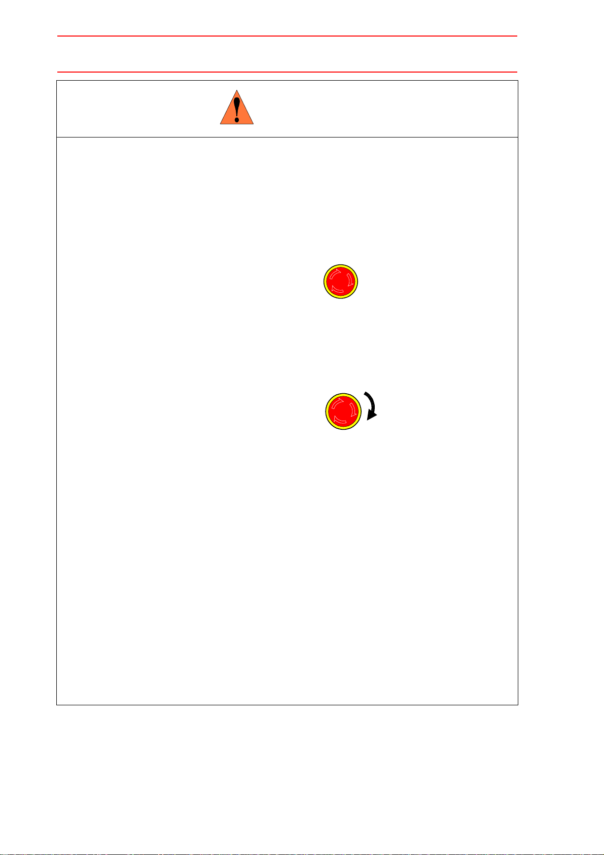
• Once the emergency stop button is released, clear the cell of all items
which could interfere with the operation of the manipulator. Then turn
the servo power ON
Injury may result from unintentional or unexpected manipulator motion.
TURN
Release of Emergency Stop
• Observe the following precautions when performing teaching operations
within the P-point maximum envelope of the manipulator:
- View the manipulator from the front whenever possible.
- Always follow the predetermined operating procedure.
- Ensure that you have a safe place to retreat in case of emergency.
Improper or unintended manipulator operation may result in injury.
• Confirm that no person is present in the P-point maximum envelope of
the manipulator and that you are in a safe location before:
- Turning ON the NX100 power
- Moving the manipulator with the programming pendant
- Running the system in the check mode
- Performing automatic operations
Injury may result if anyone enters the P-point maximum envelope of the manipulator during operation. Always press an emergency stop button immediately if there is a problem.
The emergency stop buttons are located on the right of the front door of the NX100 and
the programming pendant.
iv
Page 15

CAUTION
• Perform the following inspection procedures prior to conducting manipulator teaching. If problems are found, repair them immediately, and be
sure that all other necessary processing has been performed.
-Check for problems in manipulator movement.
-Check for damage to insulation and sheathing of external wires.
• Always return the programming pendant to the hook on the NX100 cabinet after use.
The programming pendant can be damaged if it is left in the manipulator’s work area, on
the floor, or near fixtures.
• Read and understand the Explanation of the Warning Labels in the
NX100 Instructions before operating the manipulator.
Definition of Terms Used Often in This Manual
The MOTOMAN manipulator is the YASKAWA industrial robot product.
The manipulator usually consists of the controller, the programming pendant, and supply
cables.
In this manual, the equipment is designated as follows.
Equipment Manual Designation
NX100 Controller NX100
NX100 Programming Pendant Programming Pendant
Cable between the manipulator and the controller Manipulator Cable
v
Page 16

Descriptions of the programming pendant keys, buttons, and displays are shown as follows:
Equipment Manual Designation
Programming
Pendant
Character Keys The keys which have characters printed on them are
denoted with [ ].
ex. [ENTER]
Symbol Keys The keys which have a symbol printed on them are
not denoted with [ ] but depicted with a small picture.
GO BACK
ex. page key
PAGE
The cursor key is an exception, and a picture is not
shown.
Axis Keys
Numeric Keys
Keys pressed
simultaneously
“Axis Keys” and “Numeric Keys” are generic names
for the keys for axis operation and number input.
When two keys are to be pressed simultaneously,
the keys are shown with a “+” sign between them,
ex. [SHIFT]+[COORD]
Displays The menu displayed in the programming pendant is
denoted with { }.
ex. {JOB}
Description of the Operation Procedure
In the explanation of the operation procedure, the expression "Select • • • " means that the
cursor is moved to the object item and the SELECT key is pressed.
vi
Page 17

1 Outline
1.1 DCI Function . . . . . . . . . . . . . . . . . . . . . . . . . . . . . . . . . . . . . . .1-2
1.2 Stand-alone Function . . . . . . . . . . . . . . . . . . . . . . . . . . . . . . .1-3
1.3 Host Control Function . . . . . . . . . . . . . . . . . . . . . . . . . . . . . .1-4
2 For Using Data Transmission Function
2.1 Remote Mode . . . . . . . . . . . . . . . . . . . . . . . . . . . . . . . . . . . . . .2-1
2.1.1 Remote Mode . . . . . . . . . . . . . . . . . . . . . . . . . . . . . . . . . . . . . .2-1
2.1.2 Command Remote Valid/Invalid . . . . . . . . . . . . . . . . . . . . . . . .2-3
2.1.3 Display in Command Remote Mode . . . . . . . . . . . . . . . . . . . . .2-3
2.2 Serial I/F Port Assignment . . . . . . . . . . . . . . . . . . . . . . . . . .2-4
2.3 Parallel Operation of NX100 . . . . . . . . . . . . . . . . . . . . . . . .2-6
2.3.1 No Multiple-operation of DCI, Stand-alone, and Host Control
Functions . . . . . . . . . . . . . . . . . . . . . . . . . . . . . . . . . . . . . . . . . .2-6
2.3.2 File Access and Editing for a Single Target. . . . . . . . . . . . . . . .2-6
2.4 Differences from MRC/XRC . . . . . . . . . . . . . . . . . . . . . . . .2-7
2.4.1 Multiport Processing . . . . . . . . . . . . . . . . . . . . . . . . . . . . . . . . .2-7
2.4.2 Group Axes . . . . . . . . . . . . . . . . . . . . . . . . . . . . . . . . . . . . . . . .2-7
2.4.3 Coordinated Operation and Independent Operation . . . . . . . . .2-7
2.4.4 Condition Data and System Data . . . . . . . . . . . . . . . . . . . . . . .2-7
2.5 Transmission Specifications . . . . . . . . . . . . . . . . . . . . . . . .2-8
2.5.1 Basic Specifications. . . . . . . . . . . . . . . . . . . . . . . . . . . . . . . . . .2-8
2.5.2 Transmission Control Characters . . . . . . . . . . . . . . . . . . . . . . .2-8
2.5.3 Transmission Format. . . . . . . . . . . . . . . . . . . . . . . . . . . . . . . . .2-9
2.5.4 Error Control System . . . . . . . . . . . . . . . . . . . . . . . . . . . . . . . .2-10
2.5.5 Character Configuration . . . . . . . . . . . . . . . . . . . . . . . . . . . . .2-10
2.5.6 Data Link Establishment . . . . . . . . . . . . . . . . . . . . . . . . . . . . .2-10
2.5.7 Configuration of Heading and Text . . . . . . . . . . . . . . . . . . . . .2-11
2.5.8 Transmission Parameters . . . . . . . . . . . . . . . . . . . . . . . . . . . .2-11
" Transmission Control Monitoring Timer. . . . . . . . . . . . . . . .2-11
" Transmission Control Resending Sequence . . . . . . . . . . . .2-12
2.5.9 Connection of D-SUB Connector Pins. . . . . . . . . . . . . . . . . . .2-13
2.5.10 Connection . . . . . . . . . . . . . . . . . . . . . . . . . . . . . . . . . . . . . .2-13
3 DCI Function
3.1 Outline . . . . . . . . . . . . . . . . . . . . . . . . . . . . . . . . . . . . . . . . . . . . .3-1
3.2 Commands for Job Transmission . . . . . . . . . . . . . . . . . . .3-1
3.2.1 LOADJ . . . . . . . . . . . . . . . . . . . . . . . . . . . . . . . . . . . . . . . . . . . .3-1
" Function. . . . . . . . . . . . . . . . . . . . . . . . . . . . . . . . . . . . . . . . .3-1
" Configuration . . . . . . . . . . . . . . . . . . . . . . . . . . . . . . . . . . . . .3-2
3.2.2 SAVEJ . . . . . . . . . . . . . . . . . . . . . . . . . . . . . . . . . . . . . . . . . . . .3-3
vii
Page 18

" Function . . . . . . . . . . . . . . . . . . . . . . . . . . . . . . . . . . . . . . . . 3-3
" Configuration . . . . . . . . . . . . . . . . . . . . . . . . . . . . . . . . . . . . 3-3
3.2.3 DELETEJ . . . . . . . . . . . . . . . . . . . . . . . . . . . . . . . . . . . . . . . . . 3-3
" Function . . . . . . . . . . . . . . . . . . . . . . . . . . . . . . . . . . . . . . . . 3-3
" Configuration . . . . . . . . . . . . . . . . . . . . . . . . . . . . . . . . . . . . 3-3
3.2.4 SWAIT . . . . . . . . . . . . . . . . . . . . . . . . . . . . . . . . . . . . . . . . . . . 3-4
" Function . . . . . . . . . . . . . . . . . . . . . . . . . . . . . . . . . . . . . . . . 3-4
" Configuration . . . . . . . . . . . . . . . . . . . . . . . . . . . . . . . . . . . . 3-4
3.3 Commands for Variable Transmission . . . . . . . . . . . . . . 3-4
3.3.1 LOADV . . . . . . . . . . . . . . . . . . . . . . . . . . . . . . . . . . . . . . . . . . . 3-4
" Function . . . . . . . . . . . . . . . . . . . . . . . . . . . . . . . . . . . . . . . . 3-4
" Configuration . . . . . . . . . . . . . . . . . . . . . . . . . . . . . . . . . . . . 3-4
3.3.2 SAVEV . . . . . . . . . . . . . . . . . . . . . . . . . . . . . . . . . . . . . . . . . . . 3-4
" Function . . . . . . . . . . . . . . . . . . . . . . . . . . . . . . . . . . . . . . . . 3-4
" Configuration . . . . . . . . . . . . . . . . . . . . . . . . . . . . . . . . . . . . 3-4
3.4 Registering DCI Instruction . . . . . . . . . . . . . . . . . . . . . . . . . 3-5
3.5 Concurrent Tasks from Multiple Jobs . . . . . . . . . . . . . . . 3-7
3.6 DCI Parallel Execution . . . . . . . . . . . . . . . . . . . . . . . . . . . . . 3-8
" Parallel Execution Using NWAIT . . . . . . . . . . . . . . . . . . . . . 3-8
" Parallel Execution Using PSTART (Optional). . . . . . . . . . . . 3-9
3.7 Transmission Procedure . . . . . . . . . . . . . . . . . . . . . . . . . . . 3-9
3.7.1 Job Transmission . . . . . . . . . . . . . . . . . . . . . . . . . . . . . . . . . . . 3-9
" Saving Procedure . . . . . . . . . . . . . . . . . . . . . . . . . . . . . . . . . 3-9
" Loading Procedure . . . . . . . . . . . . . . . . . . . . . . . . . . . . . . . 3-10
3.7.2 Variable Transmission . . . . . . . . . . . . . . . . . . . . . . . . . . . . . . 3-12
" Saving Procedure . . . . . . . . . . . . . . . . . . . . . . . . . . . . . . . . 3-12
" Loading Procedure . . . . . . . . . . . . . . . . . . . . . . . . . . . . . . . 3-12
3.8 Axis Data Transmission Format . . . . . . . . . . . . . . . . . . . 3-14
3.9 Alarm Codes . . . . . . . . . . . . . . . . . . . . . . . . . . . . . . . . . . . . . . 3-15
4 Stand-alone Function
4.1 Outline . . . . . . . . . . . . . . . . . . . . . . . . . . . . . . . . . . . . . . . . . . . . . 4-1
4.2 Operation Flow. . . . . . . . . . . . . . . . . . . . . . . . . . . . . . . . . . . . . 4-2
4.3 Operation . . . . . . . . . . . . . . . . . . . . . . . . . . . . . . . . . . . . . . . . . . 4-3
4.3.1 Selecting External Memory Unit . . . . . . . . . . . . . . . . . . . . . . . . 4-3
4.3.2 Save . . . . . . . . . . . . . . . . . . . . . . . . . . . . . . . . . . . . . . . . . . . . . 4-4
" Saving Job . . . . . . . . . . . . . . . . . . . . . . . . . . . . . . . . . . . . . . 4-4
" Saving File . . . . . . . . . . . . . . . . . . . . . . . . . . . . . . . . . . . . . . 4-6
4.3.3 Load . . . . . . . . . . . . . . . . . . . . . . . . . . . . . . . . . . . . . . . . . . . . . 4-8
" Loading Job . . . . . . . . . . . . . . . . . . . . . . . . . . . . . . . . . . . . . 4-8
" Loading File . . . . . . . . . . . . . . . . . . . . . . . . . . . . . . . . . . . . . 4-9
4.3.4 Job Selection Mode . . . . . . . . . . . . . . . . . . . . . . . . . . . . . . . . 4-10
" Single Selection Mode . . . . . . . . . . . . . . . . . . . . . . . . . . . . 4-10
" Related Selection Mode . . . . . . . . . . . . . . . . . . . . . . . . . . . 4-10
viii
Page 19

" Switching Selection Mode . . . . . . . . . . . . . . . . . . . . . . . . . .4-11
4.3.5 Selecting Job and Data File. . . . . . . . . . . . . . . . . . . . . . . . . . .4-12
" EACH Selection. . . . . . . . . . . . . . . . . . . . . . . . . . . . . . . . . .4-12
" BATCH Selection . . . . . . . . . . . . . . . . . . . . . . . . . . . . . . . .4-12
4.4 Transmission Procedure. . . . . . . . . . . . . . . . . . . . . . . . . . .4-12
5 Host Control Function
5.1 File Data Transmission Function. . . . . . . . . . . . . . . . . . . .5-1
5.1.1 Transmission Procedure . . . . . . . . . . . . . . . . . . . . . . . . . . . . . .5-1
" Load . . . . . . . . . . . . . . . . . . . . . . . . . . . . . . . . . . . . . . . . . . .5-1
" Save . . . . . . . . . . . . . . . . . . . . . . . . . . . . . . . . . . . . . . . . . . .5-2
5.1.2 Data Management . . . . . . . . . . . . . . . . . . . . . . . . . . . . . . . . . . .5-3
5.2 Robot Control Function . . . . . . . . . . . . . . . . . . . . . . . . . . . . .5-4
5.2.1 Command Transmission . . . . . . . . . . . . . . . . . . . . . . . . . . . . . .5-4
5.2.2 List of Interlock for Commands of Host Control Function . . . . .5-5
5.2.3 Command that Handle Axis Data . . . . . . . . . . . . . . . . . . . . . . .5-7
5.2.4 Response to MOV-type Command . . . . . . . . . . . . . . . . . . . . . .5-7
5.2.5 Status Read Function . . . . . . . . . . . . . . . . . . . . . . . . . . . . . . . .5-8
" Read/Monitor Command . . . . . . . . . . . . . . . . . . . . . . . . . . . .5-8
" Read/Data Access System Commands . . . . . . . . . . . . . . .5-13
5.2.6 System Control Function . . . . . . . . . . . . . . . . . . . . . . . . . . . . .5-17
" Operation System Commands . . . . . . . . . . . . . . . . . . . . . .5-17
" Start-up System Commands . . . . . . . . . . . . . . . . . . . . . . . .5-22
" Editing System Commands . . . . . . . . . . . . . . . . . . . . . . . .5-26
" Job Selection System Commands . . . . . . . . . . . . . . . . . . .5-30
5.2.7 I/O Read/Write Function . . . . . . . . . . . . . . . . . . . . . . . . . . . . .5-31
" Transmission Procedure . . . . . . . . . . . . . . . . . . . . . . . . . . .5-32
" Read-out of I/O Signal Status . . . . . . . . . . . . . . . . . . . . . . .5-32
" Write-in of I/O Signal Status . . . . . . . . . . . . . . . . . . . . . . . .5-33
5.3 Commands for Multi-control Group and
5.4 Alarm Codes . . . . . . . . . . . . . . . . . . . . . . . . . . . . . . . . . . . . . .5-37
5.5 Interpreter Message List . . . . . . . . . . . . . . . . . . . . . . . . . . .5-38
6 Data List
6.1 Header Number List . . . . . . . . . . . . . . . . . . . . . . . . . . . . . . . .6-1
6.2 Parameter List. . . . . . . . . . . . . . . . . . . . . . . . . . . . . . . . . . . . . .6-4
Independent Control Functions
5.3.1 Commands for Multi-control Group . . . . . . . . . . . . . . . . . . . . .5-35
5.3.2 Commands for Independent Control Function. . . . . . . . . . . . .5-36
ix
. . . . . . . . . . . . . . . . . . . .5-35
Page 20

7 Comparison of Data Transmission Functions
8 Remote Function Setting
x
Page 21
1 Outline
The data transmission function is for communication with a host computer such as a personal
computer in BSC complying protocol.
The data transmission function adopts a serial transmission line and standard protocol, making easy connection to a host computer.
The data transmission function is not only for transmission of job but also for controlling robot
system by a host computer using a set of commands.
The robot commands in the ASCII code command format are easy to use and helpful for a
quick development of necessary software to be run on the host computer.
The data transmission function is divided into the following three functions.
• DCI (Data Communication by Instruction)
• Stand-alone function
• Host control function
NX100
Host computer
(personal computer, etc.)
Data transmission
1-1
Page 22
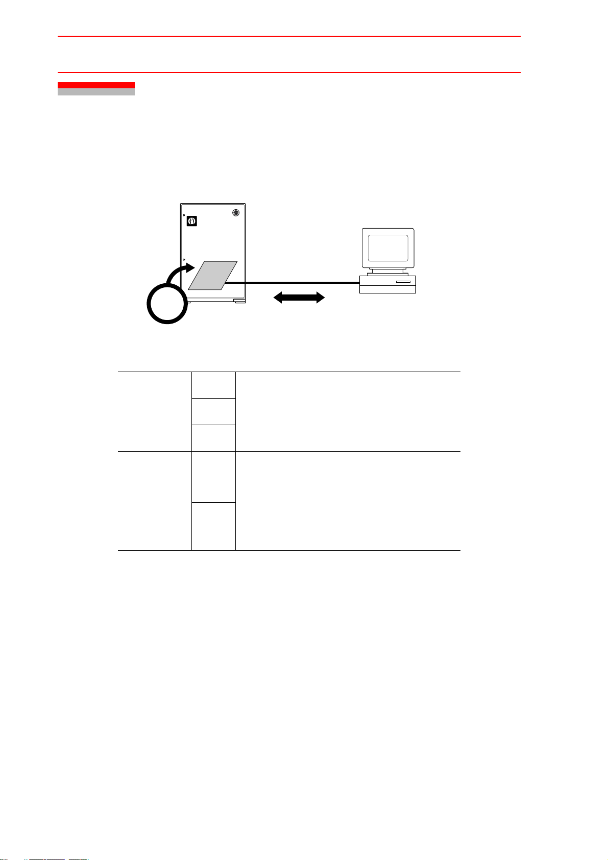
1.1 DCI Function
1.1 DCI Function
The DCI function executes instructions described in a job to perform data transmission with a
host computer. This function loads and saves jobs and variables.
NX100
Host computer
(personal computer, etc.)
Job
Execute
Job
Transmission
Variab le
Transmission
Load
Save
Delete
Load
Save
DCI Function
Job can be transmitted in either mode.
• Single job
• Related job
• Byte type global variables
• Integer type global variables
• Double precision type global variables
• Real number type global variables
• Position type global variables
(Robot axes, base axes, station axes)
1-2
Page 23
1.2 Stand-alone Function
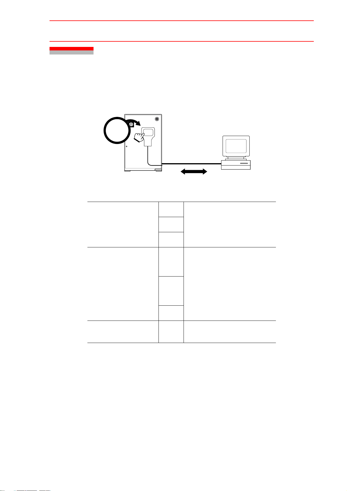
1.2 Stand-alone Function
The stand-alone function is for data transmission with host computer by operation on the programming pendant. This function loads and saves jobs and condition data.
NX100
Operation
Job Transmission
Condition Data/
General Data
Transmission
Stand-alone Function
Load
Save
Verify
Load
Save
Job can be transmitted in either
mode.
• Single job
• Related job
• Tool data
• Weaving data
• User coordinate data
• Welding data
• Variable data
Host computer
(personal computer, etc.)
System Information
Transmission
Verify
Save
• System information
• Alarm history
1-3
Page 24
1.3 Host Control Function
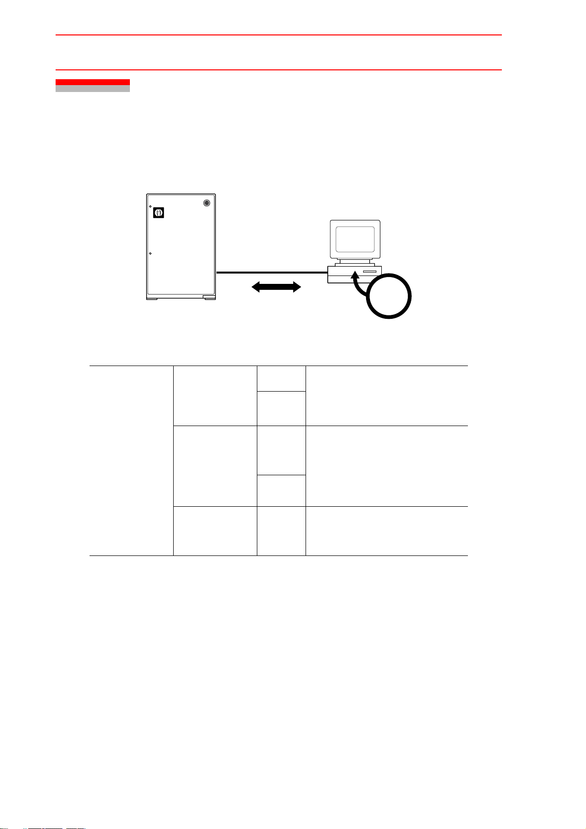
1.3 Host Control Function
The host control function is for loading and saving jobs, reading robot status, and controlling
the system by sending a command from a host computer.
NX100
Host computer
(personal computer, etc.)
Operation
File Data
Transmission
Function
Host Control Function
Job
Transmission
Condition Data/
General Data
Transmission
System
Information
Transmission
Load
Save
Load
Save
Save
Jobs can be transmitted in either
mode :
• Single job
• Related job
• Tool data
• Weaving data
• User coordinate data
• Welding data
• Variable data
• System information
• Alarm history
1-4
Page 25

Host Control Function
Status Reading
1.3 Host Control Function
• Read of error and alarm codes
• Read of current position in a joint coordinate
system
• Read of current position in a specified Carte-
sian coordinate system
• Read of mode, cycle, motion, alarm error
and servo status
• Read of current job name, line No. and step
No.
• Read of all job names or related job names
• Monitoring completion of manipulator opera-
tion
• Read of specified user coordinate data
• Read of control group and task selected sta-
tus
• Read of variable data
Robot Control
Function
System Control
• Start, hold
• Reset, cancel
• Job deletion
• Master job setup
• Job, line No. and step No. setup
• Mode and cycle selection
• Servo power supply ON/OFF
• Programming pendant interlock setup/
release
• Message display
• Joint motion and linear motion to a specified
Cartesian coordinate system
• Linear motion by increments in a specified
coordinate system
• Joint motion and linear motion to a specified
joint coordinate system
• Conversion/reverse conversion of related
job of a specified job (Relative job function is
necessary)
• Write of specified user coordinate data
• Change of control group
• Change of task to be controlled
• Write of variable data
1-5
Page 26
2.1 Remote Mode
2 For Using Data Transmission Function
2.1 Remote Mode
The data transmission function can be used with NX100 in remote mode.
2.1.1 Remote Mode
To use the data transmission function, set NX100 to remote mode.
In remote mode, the operation is ordered from a host computer ; whereas in local mode, teach
mode, and play mode, the programming pendant is used for operating the system.
To switch to the remote mode or the local mode, either
• Set the mode key on the programming pendant to [REMOTE] .
REMOTE
PLAY
TEACH
The remote mode has two sub-modes ; “I/O remote enable” and “Command remote enable”.
Which sub-mode takes effect in remote mode is set in the pseudo input display. Refer to Section 8 “Remote Function Setting”.
Teach mode
Local mode
Remote mode
Play mode
!I/O remote enable
!Command remote enable
2-1
Page 27

2.1 Remote Mode
Operation-site Mode Operation-site Condition to Enable the Operation
Local Mode Programming pendant The remote lamp is OFF, or “INHIBIT PP/
PANEL” in the pseudo input display is set to
invalid.
Remote Mode
I/O remote enable
External I/O control board
The remote lamp is ON, and “INHBIT IO” in
the pseudo input display is set invalid.
Command remote
enable
In remote mode, usually operations of the programming pendant or the playback panel is
NOTE
disabled, but they can be also enabled. To enable all operations, refer to Section 8
“Remote Function Setting”. To selectively enable some of the operations, set the parameter S2C182. For details, refer to Section 6.2 “Parameter List”.
External computer
The remote lamp is ON, and “CMD
REMOTE SEL” in the pseudo input display is
set valid.
In remote mode, operations on the programming pendant are valid except the operationrelated entries. This holds true in “I/O remote enable” and “Command remote enable” submodes. The concept is based on the conventional I/O control introduced to command control.
Note that the edit-related operations cannot be entered from more than one operating device.
In “Command remote enable” submode, to enable command remote controls only, issue the
HLOCK command. When the HLOCK command is ON, operations on the programming pendant are valid only hold and emergency stop. Also the following I/O operations are disabled :
selection between remote mode and local mode, external start, external servo ON, cycle
selection, I/O prohibit, P.P/PANEL prohibit, and master job call. Other I/O operations are valid.
2-2
Page 28

2.1 Remote Mode
2.1.2 Command Remote Valid/Invalid
Availability of each function of data transmission differs depending on the command remote
setting (Enabled / Disabled).
When the command remote is set invalid, the read/monitor system commands (hereinafter
called read-only function) in the host control function in addition to the DCI function and standalone function can be used. For the details of read/monitor system commands, refer to Section 5.2.2 “List of Interlock for Commands of Host Control Function”..
Command Remote Setting Function Availability
Invalid DCI function available
Stand-alone function available
Host control function (only read-only function) available
Valid Host control function (all commands) available
To validate the read-only function in the above host control function, set the parameter RS005
to “1”. When the command remote is validated by pressing [REMOTE] with the read-only
function valid, the command remote status is entered so that all commands can be used.
When the command remote is invalidated by pressing [REMOTE] again, the read-only function becomes validated again.
Parameter Contents and Set Value
BSC port function specification when the command
RS005
remote is invalidated
0 : DCI or stand-alone function
1 : Read-only function in host control
Initial
Value
0
2.1.3 Display in Command Remote Mode
Even in command remote enabled submode, it is not necessary to call the command remote
display because operations from NX100 is available. To call the command remote display,
select “REMOTE” from “I/O” under the top menu.
This display is used in common with the I/O remote mode display.
The message in the remote display changes according to the remote function selection.
(Refer to Chapter 8 “Remote Function Setting”.)
2-3
Page 29

REMOTE
IO and Command mode
CURR
PREV
DISP
2.2 Serial I/F Port Assignment
EDIT DISPLAY UTILITYDATA
A message shown in
the table below is displayed.
Main Menu
ShortCut
Remote Select Status
I/O
Remote
Command
Remote
Message Remarks
×דRemote mode not specified” Same when the remote lamp
is OFF.
# × “I/O mode” Only when the remote lamp
is ON.
× # “Command mode”
# # “I/O and Command mode”
Read-only Function
Valid
“Remote mode not specified” “CURR” and “PREV” are dis-
played.
# : Valid, × : Invalid
2.2 Serial I/F Port Assignment
The NX100 has one serial interface port. The FC1 protocol and the BSC complying protocol
(for data transmission function : option) can be assigned to the port to communicate with
external devices.
A change in assignment can be made only in local mode.
Parameter Contents and Set Value
Standard port protocol specification
0 : NON
RS000
1 : System reserved
2 : BSC LIKE (Data transmission
function
3 : FC1
2-4
Initial
Value
2
Page 30
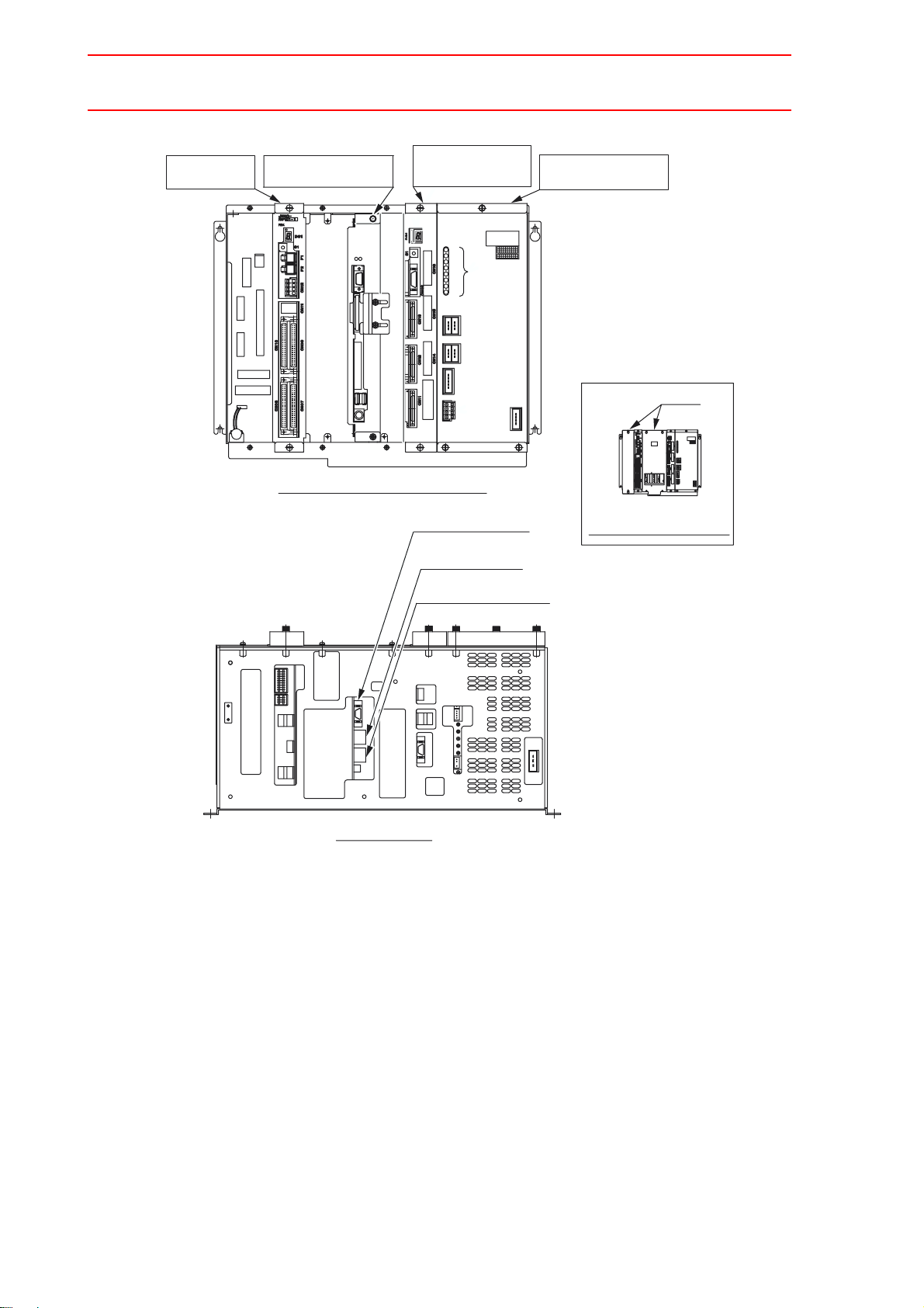
2.2 Serial I/F Port Assignment
TYPE JANCD-NCP01
Robot I/F Unit
JZNC-NIF01
CNBAT
Control Circuit Board
JANCD-NCP01
CPU
TYPE JANCD-NCP01
TYPE JANCD-NCP01
DATE
REV
LED
0
CNSP1
CNTU
CNRI
CNM
CNRO
CNFAN
ATX
1
VIDEO
IDE
USB1(L)
USB1(R)
PS2
Front View (without the cover)
Major Axes Control
Circuit Board
SGDR-AXA01A
SUPPLY
POWER
CPS-NX1
No.
DATE
Fuji
Co.,Ltd.
JAPAN
Electric
080910
03040506
07
01
02
181920
13141516
17
11
SOURCE
+5VSB
PON
+5V
+24V
OTHER
FAN
OHT
CN05
(+24V1)
CN04
(+24V2)
(REMOTE)
12
282930
23242526
27
21
22
GFEDC
BA
KJH
SRQPN
ML
VUT
CN03
(TU)
CN02
200-240V AC
CN01
(AC IN)
INPUT
50/60Hz
3A
Serial port interface
(RS-232C I/F)
(LAN2)
Ethernet function
(LAN1)
Programming Pendant
Control Circuit Board
CPS-420F
Cover
Front View
(with the cover supplied)
Bottom View
CPU Unit Configuration (JZNC-NRK 01!-!)
2-5
Page 31

2.3 Parallel Operation of NX100
2.3 Parallel Operation of NX100
The NX100 is capable of parallel processing. For instance, it can check signals with programming pendant while saving files to YASNAC FC2, or can edit files with the programming pendant while monitoring operation status by the host control function.
The parallel operation has the following restrictions. When an operation against these restrictions is made, a warning message is displayed.
Operation Warning
YASNAC FC2
Stand-alone
Programming pendant
DCI Alarm
Host control Interpreter message
Error message for 3 seconds
(or error message)
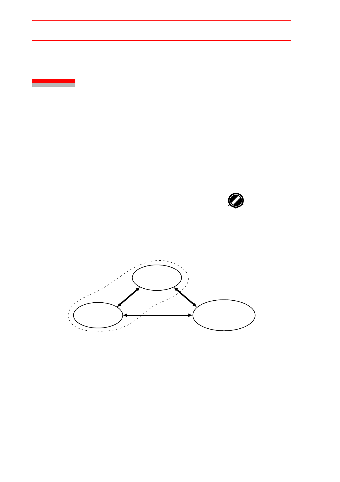
2.3.1 No Multiple-operation of DCI, Stand-alone, and Host Control Functions
All DCI, stand-alone, and host control use BSC LIKE protocol and the same port, therefore
these functions cannot be performed by parallel processing.
Warning message : Serial port not defined
Warning message : Serial port being used
Warning message : Protocol being used
2.3.2 File Access and Editing for a Single Target
Access to a single target file is available. Parallel processing of reads from two or more
sources is impossible.
During access to a file for other function, the HLOCK command of the host control function
cannot be issued.
Key operations are ignored while the HLOCK command is ON.
Warning message : Data accessed with other functions
2-6
Page 32

2.4 Differences from MRC/XRC
2.4 Differences from MRC/XRC
The data transmission function in NX100 is intended to reuse basically the user applications
with succession to the data transmission of MRC/XRC.
There are some differences resulted from functional differences between the MRC/XRC and
the NX100.
2.4.1 Multiport Processing
The XRC is not applicable for multiport processing.
2.4.2 Group Axes
The control group information used for the CGROUP and RGROUP commands in the host
control function differs depending on the number of manipulators.
2.4.3 Coordinated Operation and Independent Operation
Up to 8 tasks (6 tasks for XRC) can be changed by the CTASK command. No command
related to coordinated operation is available.
2.4.4 Condition Data and System Data
Condition data and system data have different file name in option function, accordingly their
communication header differ.
2-7
Page 33

2.5 Transmission Specifications
2.5 Transmission Specifications
This section explains the transmission specifications for the data transmission.
2.5.1 Basic Specifications
Interface Complies to RS-232C (RS/CS method)
Transmission Speed
Transmission Mode
Synchronization
system
Protocol
Transmission Code
Error Check
Response Method
9600 bps
Half-duplex transmission system (point-topoint)
Asynchronous (stop bit 1 *
BSC LIKE
ASCII, shift JIS
8-bit data length *
Even parity *
Nontransparent
BCC
ACK alternating response
1
1
1
*1 Can be changed by transmission parameter setting
2.5.2 Transmission Control Characters
)
The transmission control characters are shown in the table below.
Transmission Control Characters and Codes
Control
Character
DLE
SOH
STX
ETX
EOT
ENQ
NAK
ETB
ACK0
ACK1
Code
(hexadecimal)
10
01
02
03
04
05
15
17
10, 30
10, 31
Meanings of Control Character
Data Link Escape
Start of Heading
Start of Text
End of Text
End of Transmission
Enquiry
Negative Acknowledgment
End of Text Block
Even Affirmative Acknowledgment
Odd Affirmative Acknowledgment
2-8
Page 34

2.5 Transmission Specifications
2.5.3 Transmission Format
The transmission format is as follows.
S
HEADING
O
H
S
O
HEADING
H
S
T
X
S
T
X
E
N
Q
E
O
T
TEXT
TEXT
S
T
X
S
T
X
TEXT
TEXT
E
T
B
E
T
X
BCC
BCC
E
BCC
T
B
E
T
BCC
X
N
A
K
ACK0
ACK1
2-9
Page 35

2.5 Transmission Specifications
2.5.4 Error Control System
The error control is performed by a check sum of all the characters from SOH or STX to ETB
or ETX.
The check sum is calculated as shown below.
<Example>
E
BCC
T
X
+
0000 0001 1101 1011
0000 0101
0000 0000
0011 0110
1010 1100
1111 0001
0000 0011
S
TEXT
T
X
• Start of calculation : Calculation is started when SOH or STX used as the block start
sequence appears. These block start sequence are not included in
the sum. As for a STX led by a SOH, STX is included in the sum.
• End of calculation : Calculation is ended when ETB or ETX used as the block end
sequence appears, with the ETB or ETX included in the sum.
2.5.5 Character Configuration
The character configuration is as follows.
Start bit
b1 b2 b3 b4 b5 b6 b7 b8 bp
2.5.6 Data Link Establishment
A data link is established by responding ACK0 to ENQ.
Stop bit
Parity bit
2-10
Page 36

2.5 Transmission Specifications
2.5.7 Configuration of Heading and Text
The configuration of heading and text is as follows.
Heading 6 characters fixed Max. 256 characters
S
O
H
S
T
X
Subcode No.
, (comma)
Header No.
TEXT BCC
E
T
B
2.5.8 Transmission Parameters
" Transmission Control Monitoring Timer
Two timers are provided for transmission control monitoring. Both are transmission parameters so that their settings can be changed for each system.
Timer A : Sequence monitoring timer. Serves as protection against invalid or no response.
Recommended value is 3 sec.
Timer B : Text reception monitoring timer. Serves as protection against no response of text
end character. Recommended value is 20 sec.
Timer B
Timer B
NX100
ACK0
ACK1
ENQ
Data
EOT
Host
computer
Timer A
Timer A
NX100
ENQ
Data
EOT
Host
computer
ACK0
ACK1
2-11
Page 37

2.5 Transmission Specifications
" Transmission Control Resending Sequence
Two constants below are related to the transmission control resending sequence. Both are
transmission parameters like the transmission control monitoring timers, whose settings can
be changed for each system.
Retry 1 : Number of resendings of a sequence character at an invalid or no response
at all. Recommended value is 10 times.
Retry 2 : Number of resendings of a text at a block check error (reception of NAK).
Recommended value is 3 times.
Parameter Contents and Set Value
RS030 Number of data bits 7 : 7 (bit)
8 : 8 (bit)
RS031 Number of stop bits 0 : 1 (bit)
1 : 1.5
2 : 2
RS032 Parity specification 0 : No specification
1 : Odd parity
2 : Even parity
RS033 Transmission speed specification 1 : 150 (baud rate)
2 : 300
3 : 600
4 : 1200
5 : 2400
6 : 4800
7 : 9600
8 : 19200
RS034 Timer A Sequence monitoring timer
Serves as protection against invalid or no response
Unit : 0.1 sec. (Setting range : 0 to 100)
Initial
Value
8
0
2
7
30
RS035 Timer B Text reception monitoring timer
Serves as protection against no response of text end character
Unit : 0.1 sec. (Setting range : 0 to 255)
RS036 Retry 1 Number of resendings of a sequence character at an invalid or
no response (Setting range : 0 to 30)
RS037 Retry 2 Number of resendings of a text at a block check error (reception
of NAK). (Setting range : 0 to 10)
RS038 Block check method 0 : Check sum 0
2-12
200
10
3
Page 38

2.5 Transmission Specifications
2.5.9 Connection of D-SUB Connector Pins
The connection of D-SUB connector pins is shown below.
NCP01 board (D-SUB9P)
NX100
Carrier detect
1
CD
Data receive
2
RD
Data send
3
SD
Data terminal ready
4
ER
Grounding for signal
5
SG
Request to send
7
RS
Sending enabled
8
CS
Protective grounding
9
FG
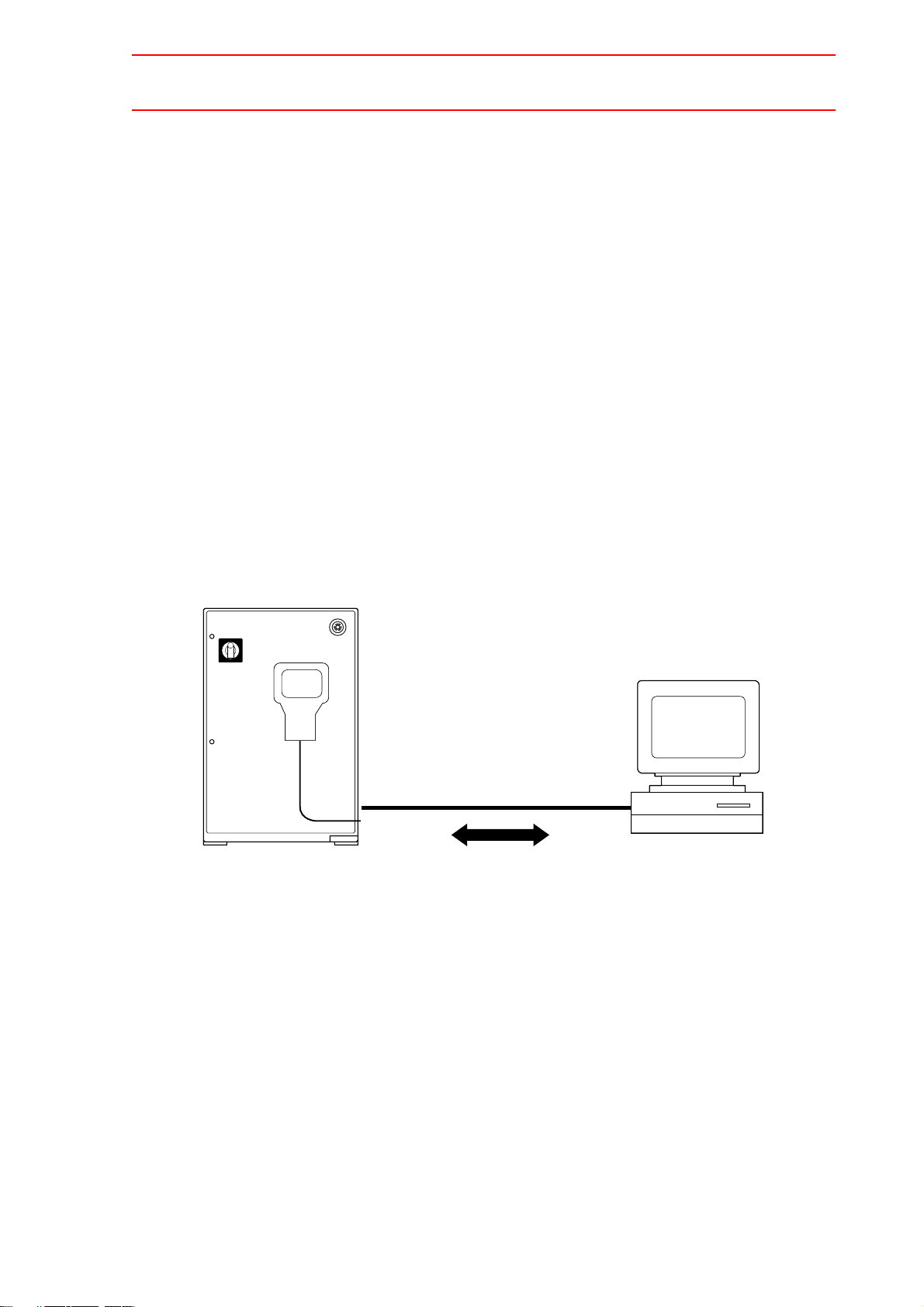
2.5.10 Connection
Since the system is “null-modem”, connect the pins as shown below.
XCP01 board
Host Computer
3
SD
2
RD
7
RS
8
CS
5
SG
NX100
2
3
5
7
8
9
RD
SD
SG
RS
CS
FG
• Connect “RS” of the NX100 to “CS” of a host computer. This prevents data overrun when
reception processing speed of the NX100 cannot catch up with data sending from the
host computer. In other words, “RS” signal from the NX100 controls start-hold of data
transmission from the host computer. The sending interface controller must be capable of
coping with CS input displacement in units of a single byte.
• The NX100 sends data when the “CS” signal is ON.
2-13
Page 39

3.1 Outline
3 DCI Function
3.1 Outline
The data communication by instruction (DCI) function loads, saves jobs and variables according to an instruction that executes data transmission with a host computer. The DCI function
is classified as follows.
• Job load, save and delete functions
• Variable load and save functions
NX100
Host computer
(personal computer, etc.)
Job
Execute
3.2 Commands for Job Transmission
3.2.1 LOADJ
" Function
Loads specified jobs as single or related jobs, from the external memory unit to the memory of
the NX100.
3-1
Page 40

3.2 Commands for Job Transmission
" Configuration
LOADJ
JOB:<Job name>
IG#<Input group No.>
B<Variable No.>
Unit of
loading
JBI, JBR
NWAIT
IF statement
• If the NX100 memory already contains a job having the same name as the job to be
loaded, the existing job is deleted and the new job is loaded. However, if the job to be
loaded is as follows, an alarm occurs.
• Execution starting job
• Job under execution/halting
• Job registered in job call stack
• Specify input group numbers (BCD/BIN, parity specification), and variable numbers in the
same way as for the CALL command. If the pattern input value is 0, the operation is not
executed. A variable number 0 is valid.
• Unit of loading : Select either a single job (JBI) or related jobs (JBR)
• When the NWAIT is specified, the next instruction is executed without waiting completion
of job loading.
• While a job is being loaded by the LOADJ command for which NWAIT is specified, if an
access is attempted to a job called by the CALL command or JUMP command, an alarm
occurs. If a LOADJ or SAVEJ command has already been executed, a job is loaded after
completion of the execution.
3-2
Page 41

3.2 Commands for Job Transmission
3.2.2 SAVEJ
" Function
Saves a specified job as single or related jobs, from the memory of the NX100 to the external
memory unit.
" Configuration
SAVEJ
JOB:<Job name>
IG#<Input group No.>
B<Variable No.>
Unit of saving
JBI, JBR
NWAIT
IF statement
• Specify input group numbers (BCD/BIN, parity specification), and variable numbers in the
same way as for the CALL command. If the pattern input value is 0, the operation is not
executed. A variable number 0 is valid.
• Unit of saving : Select either a single job (JBI) or related jobs (JBR).
• When the NWAIT is specified, the next command is executed without waiting completion
of job saving. When a LOADJ or SAVEJ command has already been executed, a job is
saved after completion of the execution.
3.2.3 DELETEJ
" Function
Deletes all jobs except its own job or specified jobs as single or related jobs, from the memory
of the NX100.
" Configuration
DELETEJ
Unit of
JOB:<Job name>
deleting
JBI, JBR
• Unit of deleting : Select either a single job (JBI) or related jobs (JBR).
• The following jobs cannot be deleted.
• Execution starting job
• Job under execution/halting
• Job registered in job call stack
3-3
IF
statement
Page 42

3.3 Commands for Variable Transmission
3.2.4 SWAIT
" Function
Waits for completion of loading or saving jobs or variables.
Use this command to recognize a completion of LOADJ, SAVEJ, LOADV, and SAVEV commands when a NWAIT is specified for these instructions.
" Configuration
SWAIT
3.3 Commands for Variable Transmission
3.3.1 LOADV
" Function
Loads the specified global variables from an external memory unit to the NX100 memory.
" Configuration
LOADV
Byte type global variable
Integer type global variable
Double precision type global variable
Real number type global variable
Position type (robot axis) global variable
Position type (base axis) global variable
Position type (station axis) global
variable
NWAIT
3.3.2 SAVEV
" Function
Saves the specified global variables from the NX100 memory to a external memory unit.
" Configuration
SAVEV
Byte type global variable
Integer type global variable
Double precision type global variable
Real number type global variable
Position type (robot axis) global variable
Position type (base axis) global variable
Position type (station axis) global
variable
3-4
NWAIT
Page 43

3.4 Registering DCI Instruction
CONTROL GROUP R1 TOOL 00
CO O
Operation Explanation
1 Move the cursor to the
address area.
3.4 Registering DCI Instruction
2 Move the cursor to the line
where an instruction is to be
In the job content display in teach mode, move the cursor to the
line just above the place where an instruction is to be registered.
registered in the job content
0019
MOVJ
display.
Line just above
the place where
an instruction is
to be registered
0020
0021
0022
0023
0024
0025
0026
0027
MOVL
MOVL
MOVJ
DOUT
MOVJ
MOVL
MOVL
MOVL
VJ=50.00
V=138
V=138
VJ=100.00
OT#(1) ON
VJ100.00
V=138
V=138
V=138
LOADJ
SAVEJ
LOADV
SAVEV
DELETEJ
DEVICE
MOTION
ARITH
SHIFT
OTHER
SAME
3 Press [INFORM LIST]. The instruction list dialog is displayed. The cursor moves to the
instruction list dialog while the cursor in the address area
changed to an underline.
MOVJ
MOVL
MOVL
MOVJ
DOUT
MOVJ
MOVL
MOVL
MOVL
EDIT DISPLAY
TEST
R1
VJ=50.00
V=138
V=138
VJ=100.00
OT#(1) ON
VJ100.00
V=138
V=138
V=138
ShortCut
UTILITY
STEP NO.
TOOL
015
00
IN/OUT
CONTROL
DEVICE
LOADJ
MOTION
SAVEJ
ARITH
LOADV
SHIFT
SAVEV
OTHER
DELETEJ
SAME
PRIOR
SWAIT
JOB
JOB CONTENT
JOB NAME
CONTROL GROUP
0019
0020
0021
0022
0023
0024
0025
0026
0027
LOADJ JOB:JOB JBI
Main Menu
4 Select an instruction to be reg-
istered.
The instruction where the cursor is positioned is displayed with
the previously registered additional items in the input buffer line.
JOB CONTENT
JOB NAME
CONTROL GROUP
0019
0020
0021
0022
0023
0024
0025
0026
0027
MOVJ
MOVL
MOVL
MOVJ
DOUT
MOVJ
MOVL
MOVL
MOVL
LOADV B000
TEST
VJ=50.00
V=138
V=138
VJ=100.00
OT#(1) ON
VJ100.00
V=138
V=138
V=138
STEP NO.
TOOL
R1
015
00
LOADJ
SAVEJ
LOADV
SAVEV
DELETEJ
SWAIT
IN/OUT
CONTROL
DEVICE
MOTION
ARITH
SHIFT
OTHER
SAME
PRIOR
3-5
Page 44

3.4 Registering DCI Instruction
Operation Explanation
5 Change the additional items
and variable data.
<To register items as displayed in the input buffer>
Perform operation described in the step 6 below.
<To edit any additional items>
With the cursor on the instruction to be registered, press
[SELECT]. The cursor moves to the input buffer line.
LOADV B000
• Changing a numerical value data of additional items
Move the cursor to the additional item whose numerical value is to be
changed. Pressing simultaneously [SHIFT] and the cursor key increments or decrements the value.
LOADV B000
To enter a value by pressing the number key, press [SELECT] to display the input line.
B=
LOADV
Enter a value, then press [ENTER]. The value displayed in the input
line is changed.
• Adding, changing, or deleting the additional items
To add, change or delete the additional items, select an instruction in
the input buffer line to display the detail edit display.
EDIT DISPLAY UTILITYJOB
DETAIL EDIT
LOADV
VARIABLE
NWAIT
To add an additional item, select “NOT USED” of an additional item
selection status, then display the selection dialog to select an additional
item to be added.
To delete an additional item, move the cursor to an additional item to be
deleted, then select “NOT USED” to delete.
LOADV B000
B000
UNUSED
ShortCutMain Menu
DETAIL EDIT
LOADV
VARIABLE
NWAIT
3-6
B000
NWAIT
UNUSED
Page 45

3.5 Concurrent Tasks from Multiple Jobs
Operation Explanation
5 (cont’d) • Changing the data type
To change the data type of additional item, move the cursor to the of
the additional item and press [SELECT] to select a data type.
DISPLAY UTILITY
JOB
DETAIL EDIT
LOADV
VARIABLE
NWAIT
EDIT
B000
UNUSED
B
I
O
R
P
After having added, changed or deleted the addtional items, press
[ENTER]. The detail edit display is ended and the job content display
appears.
6 Press [INSERT] and [ENTER]. The instruction displayed in the input buffer line is registered.
To register an instruction just before an END instruction, it is not
necessary to press [INSERT].
JOB CONTENT
JOB NAME
CONTROL GROUP
0020
0021
0022
0023
0024
0025
0026
0027
0028
TEST
MOVL
V=138
MOVL
V=138
LOADV
I000
MOVJ
VJ=100.00
DOUT
OT#(1) ON
MOVJ
VJ100.00
MOVL
V=138
MOVL
V=138
MOVL
V=138
STEP NO.
TOOL
R1
015
00
IN/OUT
CONTROL
DEVICE
MOTION
ARITH
SHIFT
OTHER
SAME
PRIOR
3.5 Concurrent Tasks from Multiple Jobs
As an option, commands related to DCI function can be executed from more than one job
simultaneously. The operations are explained below.
• The DCI related commands can be executed in any job regardless of distinction among
the ordinary job, concurrent job (option), or job activated in series (option).
• Multiplexing of DCI transmission function is not supported. Therefore, it is impossible to
manipulate files on two or more external memory units (such as personal computer) connected to the NX100.
• If two or more commands related to DCI function are issued concurrently, the execution
starts after completion of processing of the currently executing command. Therefore, if a
module issues a command request while another module is executing DCI function, the
request has to wait until the ongoing processing completes.
3-7
Page 46

3.6 DCI Parallel Execution
3.6 DCI Parallel Execution
By using the function described below, the DCI instruction can be executed in parallel with
general instructions such as a move instruction and operating instruction. When this function
is used, the robot can be moved or the calculation is executed during data transmission ; this
function is effective for reduction of tact time, etc.
" Parallel Execution Using NWAIT
NOP
MOVJ VJ=50.00
MOVJ VJ=50.00
LOADJ JOB:ABC JBI NWAIT
MOVJ VJ=50.00
MOVJ VJ=50.00
SWAIT
CALL JOB:ABC
) ) )
END
$
%
&
'
(
In the above job, when the command $ is executed, loading of the host computer and the job
are executed. Normally, when NWAIT is not specified, the commands of % and after are not
executed until the job loading is completed. However, when NWAIT is specified, the commands % and & are executed sequentially during the job loading ; at execution of SWAIT
command ', the execution of command ( is waited for the job “ABC” loading is completed.
At the time of completion of job “ABC” loading, the command ( is executed to execute the
job “ABC”.
At this time, if SWAIT command is not specified before the command (, the command ( is
executed during the loading of job “ABC”, and an alarm occurs. Therefore, be sure to verify
that loading is completed before executing a job to be loaded, by using SWAIT command.
To load/save variables, be sure to input a SWAIT command before using variables to be
loaded/saved as shown below.
(Correct) (Wrong)
NOP
) ) )
LOADV B000 NWAIT
) ) )
SWAIT
SET B001 B000
NOP
) ) )
LOADV B000 NWAIT
) ) )
SET B001 B000
3-8
Page 47

3.7 Transmission Procedure
" Parallel Execution Using PSTART (Optional)
By using an independent control command (optional), DCI commands can be executed in parallel with general commands. For example, to execute the job “R1” for robot 1 is to be executed in parallel with the job “S1” for station 1 during job loading, the following procedure is
taken :
Job “R1” : Job for robot 1
Job “S1” : Job for station 1
[JOB:R1]
NOP
MOVJ VJ=50.00
MOVJ VJ=50.00
PSTART JOB:S1 SUB1
LOAD JOB:ABC
PWAIT
CALL JOB:ABC
END
When PSTART command $ is executed, the job “S1” starts execution in parallel with the job
“R1”. The job “ABC” is loaded by the command % during execution of the job “S1” ; when
loading is completed, the NX100 waits for the job “S1” to be completed by the command &.
When the execution of job “S1” is completed, the job “ABC” is executed by the command '.
$
%
&
'
[JOB:S1]
NOP
MOVJ VJ=50.00
MOVJ VJ=50.00
END
3.7 Transmission Procedure
3.7.1 Job Transmission
" Saving Procedure
The transmission from the NX100 to a host computer proceeds as follows.
NX100 → Host computer
1. The ENQ code is sent out to establish a data link.
2. After the data link is established, data are sent out to the host computer.
3. After the transmission completes, the NX100 waits for a response from the host com-
puter to verify the completion of transmission. Therefore, the host computer should
return a response.
4. The transmission is terminated upon receipt of the response from the host computer.
3-9
Page 48

3.7 Transmission Procedure
The data type is distinguished by the header number and the subcode number. Refer to the
header number list.
ENQ
ACK0
SOH 02, 001 STX File name
*1
ETB BCC
ACK1
STX
STX ETX BCCData
NX100
EOT
ACK0
ACK1
*1
File name : CR (File name does not include extension.)
ETB BCCData
SOH 90, 000 STX Data ETX BCC
*3
*2 ACK0 or ACK1
*3 Normal completion : 0000CR (ASCII code)
Abnormal completion : Integer except 0000 CR (ASCII code)
ACK0
*2
ACK
Host computer
ENQ
EOT
" Loading Procedure
The transmission from a host computer to the NX100 proceeds as follows.
Host computer → NX100
1. The ENQ code is sent out to establish a data link.
2. After the data link is established, a request to send is sent out to the host computer.
3. When the request to send is accepted, the NX100 enters receiving status, waiting for
the ENQ code from the host computer. Therefore, the host computer should send data
after the data link is established.
4. The transmission is terminated at completion of data reception from the host computer.
A request to send consists of a header number and a subcode number. Refer to the header
number list.
3-10
Page 49

3.7 Transmission Procedure
At transmission, memory capacity is checked and if received data cannot be stored, an alarm
occurs. If the transmission itself is normal, reception is continued and an alarm is displayed
after the transmission is terminated. If an error occurs during reception, the job data will not
be stored.
ENQ
ACK0
STX
*1
ETX BCC
1
*
ACK1
ENQ
Host computer
ETB BCCData
SOH 02, 051 STX File name
EOT
ACK0
SOH 02, 001 STX File name ETB BCC
NX100
ACK1
STX ETX BCCData
*2
ACK
*1
File name : CR (File name does not include extension.)
*2 ACK0 or ACK1
EOT
3-11
Page 50

3.7 Transmission Procedure
3.7.2 Variable Transmission
The variable transmission is performed in the same way as for the data as shown below.
" Saving Procedure
ENQ
ACK0
1
SOH 03,001 STX
EOT
Data
*
CR
ETX BCC
ACK1
NX100
ACK0
ACK1
" Loading Procedure
ENQ
SOH 03,051 STX
EOT
NX100
ACK0
SOH 90,000 STX Data
ETX BCC
SOH 03,001 STX
Data
ENQ
Host computer
*2
CR
ETX BCC
EOT
ACK0
ACK1
ENQ
Host computer
1
*
CR
ETX BCC
ACK1
For headers, refer to the header number list.
EOT
3-12
Page 51

3.7 Transmission Procedure
*1
Byte type global variable : +++ (0 to 255)
Integer type global variable : ± +++ (-32768 to +32767)
Double precision type global variable :
Real number type global
variable :
Position type (robot axis)
global variable :
Position type (base axis)
global variable :
± ++++++++++ (-2147483648 to 2137383647)
7 significant digits (-1.70141E+38 to +1.70141E+38)
Pulse type or XYZ type depending on the internal setting status
Pulse type
S, L, U, R, B, T (Unit : pulse)
(-999999999 to 999999999)
XYZ type
X, Y, Z, TX, TY, TZ, TYPE
d0 = 0 : Flip d0 = 1 : No flip
d2 = 0 : Up d2 = 1 : Back
Unit : degree (°), significant 2 decimal points
-9999.99 to 9999.99
Unit : mm, significant 3 decimal points
-999999.999 to 999999.999
Pulse type or XYZ type depending on the internal setting status
Pulse type
1, 2, 3 (Unit : pulse)
(-999999999 to 999999999)
Position type (station axis)
global variable :
*2
0000 or error code
The response is as follows when an error occurs in response.
SOH 90,000 STX DATA CR ETX BCC
If a stop operation (hold and emergency stop) is done during data transmission (while
jobs or variables are loaded or saved), the robot stops but the data transmission continues. In this case, the start lamp goes OFF. The restart will not be accepted until completion of the data transmission.
XYZ type
X, Y, Z (Unit : mm, significant 3 decimal points)
(-999999.999 to 999999.999)
Pulse type
1, 2, 3, 4, 5, 6 (Unit : pulse)
(-999999999 to 999999999)
3-13
Page 52

3.8 Axis Data Transmission Format
3.8 Axis Data Transmission Format
The NX100 data transmission function has the following restrictions on transmission of the
NX100 internal data.
The robot axes are fixed to a 6-axis set.
A base axis and a station axis are recognized as an external axis. Up to three base axes are
available. With station axis data added after base axis data, up to six axes can be handled.
For example, SAVEV BP005 is read as SAVEV BP005 + EX005.
If the system lacks one of the variables, only the existing one is used. If the system has both
variables but not registered, an error occurs.
The definition of the robot, base, and station axes is used as it is, free of the predetermined
axis data R1, B1, and S1.
<Example>
Transmission data of SAVEV in different system configurations are shown below.
• In a system having two base axes (X and Z) and no station axis
If BP005 is pulse type and 1st axis is 100 and 2nd axis is 200, then
SAVEV BP005 → 03, 007 100, 200, 0, 0, 0, 0
If BP005 is XYZ type and X-axis is 123.456 and Z-axis is 234.567, then
SAVEV BP005 → 03, 008 123.456, 234.567, 0,0, 0, 0
• In a system having no base axis and three station axes
If EX005 is pulse type and 1st axis is 500, 2nd axis is 600, and 3rd axis is 700
SAVES EX005 → 03, 007 500, 600, 700, 0, 0, 0
• In a system having two base axes (X and Z) and three station axes
If BP005 is pulse type, 1st axis is 100 and 2nd axis is 200, and
EX005 is pulse type, 1st axis is 500, 2nd axis is 600, and 3rd axis is 700, then
SAVEV BP005 → 03, 007 100, 200, 500, 600, 700, 0
(Same as for SAVEV EX005)
If BP005 is XYZ type, X axis is 123.456, and Z axis is 234.567, and
EX005 is pulse type, 1st axis is 500, 2nd axis is 600, and 3rd axis is 700, then
SAVEV BP005 → 03, 008 123.456, 234.567, 500, 600, 700, 0
(same as for SAVEV EX005)
3-14
Page 53

3.9 Alarm Codes
Code Message Data
3.9 Alarm Codes
4104
4105
4106
Data Contents
001
002
003
004
012
Insufficient memory capacity
Job editing prohibited
Attempted to load or delete a job being executed.
No specified job
Position data destroyed
WRONG EXECUTION OF
LOAD INST
WRONG EXECUTION OF
SAVE INST
WRONG EXECUTION OF
DELETE INST
Refer to the
table below.
013
017
019
020
023
024
090
104
111
112
113
117
118
Position variable not registered
Instruction destroyed
Invalid character in job name
Invalid character in label
Invalid character in this system
Syntax error
Control command sending/receiving error (Ethernet)
Error response from host computer
Syntax error
Error in position data
No NOP or END instruction
Format error
Invalid number of data
3-15
Page 54

3.9 Alarm Codes
Data Contents
120
122
125
126
127
128
211
212
213
214
221
222
223
Data range exceeded
Destroyed file exists
No serial port setting
This serial port already used.
This protocol already used.
File accessing in other function
System block error (Receiving EOT while waiting ACK)
System block error (Receiving EOT at starting receiving)
System block error (Receiving EOT before receiving the last block)
System block error (Receiving codes other than EOT before receiving the last block)
Sending error (Retry for NAK exceeded)
Sending error (Timeup for timer A retry)
Sending error (ACK0/ACK1 order error after retry)
231
232
233
234
235
236
237
240
241
242
243
Receiving error (Timeup for timer A while waiting ACK after ENQ, timeup for timer A while
waiting ENQ response)
Receiving error (Timeup for timer B while receiving a text)
Receiving error (Heading length is shorter than 6 characters)
Receiving error (Heading length is longer than 6 characters)
Receiving error (Header number error)
Receiving error (Text length exceeds 256 bytes)
Receiving error (Receiving other than ENQ while waiting ENQ, receiving other than control code while waiting control code, receiving other than STX, SOH, ENQ, EOT while
waiting text)
Software error
Hardware error (Overrun)
Hardware error (Parity error)
Hardware error (Framing error)
244
245
Hardware error (Sending timeup (timer A))
Hardware error (Sending timeup (timer B))
3-16
Page 55

4.1 Outline
4 Stand-alone Function
4.1 Outline
In stand-alone mode, the file data transmission function is available. By the operations on the
NX100 programming pendant, file data can be sent from the NX100 to a host computer such
as personal computer to be saved, and from a host computer to the NX100 memory to be
loaded.
Load : Transmits file data from a host computer to the NX100.
Save : Transmits file data from the NX100 to a host computer.
Verify : Verifies data between the NX100 and the host computer and informs if some parts are
not matched.
NX100
Operation
The following data can be transmitted between the NX100 and a host computer. System
information can be saved but not loaded.
• Job data
• Condition data/General data
• System information
Host computer
(personal computer, etc.)
4-1
Page 56

4.2 Operation Flow
4.2 Operation Flow
Transmission of file data is performed in the following manner.
<Top menu>
{EXT MEM}
Sub menu
{LOAD} {SAVE} {VERIFY} {DEVICE}
Select a data group
Select a data
Press "EXECUTE"
End
Select a
device
4-2
Page 57

4.3 Operation
4.3.1 Selecting External Memory Unit
Operation Explanation
1 Select {FD/PC CARD} under
the main menu.
2 Select {DEVICE}. The device selection display is shown.
4.3 Operation
EDIT
DATA
FLOPPY DISK/CompactFlash
DEVICE
DISPLAY
CompactFlash
ShortCutMain Menu
3 Select “DEVICE”. The selection dialog is shown.
EDIT DISPLAY UTILITYDATA
FLOPPY DISK/CompactFlash
DEVICE
FC1
FC2
PC
CompactFlash
UTILITY
4 Select the device to be
changed.
ShortCutMain Menu
The device is changed.
EDIT
FLOPPY DISK/CompactFlash
DEVICE
Main Menu
PC
ShortCut
4-3
DISPLAY
UTILITYDATA
Page 58

4.3 Operation
4.3.2 Save
The operation to transmit data from the NX100 to the external memory unit is explained in the
following.
" Saving Job
Operation Explanation
1 Select {FD/PC CARD} under
the main menu.
2 Select {SAVE}. The external memory menu display is shown.
EDIT DISPLAY UTILITYD ATA
FLOPPY DISK/CompactFlash
SAVE
PC
JOB
FILE/GENERAL DATA
SYSTEM INFORMATION
Main Menu
ShortCut
3 Select “JOB”. The external memory job list display is shown.
DISPLAY
EDIT
FLOPPY DISK/CompactFlash
PC (SAVE) SINGLE NO. 7
TEST001
TEST002
TEST004
TEST005
TEST007
TEST003
TEST006
UTILITYDATA
PAGE
ShortCutMain Menu
4 Select the job to be saved. The select job is marked with “,“.
DISPLAY
EDIT
FLOPPY DISK/CompactFlash
PC (SAVE) SINGLE NO. 7
TEST001
TEST002
TEST004
TEST005
TEST007
TEST003
TEST006
UTILITYDATA
4-4
PAGE
ShortCutMain Menu
Page 59

4.3 Operation
Operation Explanation
5 Press [ENTER]. The confirmation dialog is shown.
DISPLAY
EDIT
FLOPPY DISK/CompactFlash
PC (SAVE) SINGLE NO. 7
TEST001
TEST002
TEST004
TEST005
TEST007
UTILITYDATA
TEST003
TEST006
Save?
YES NO
PAGE
ShortCutMain Menu
6 Select “YES”. The job starts to be saved, and the transmission display is shown.
EDIT DISPLAY UTILITYDATA
FLOPPY DISK/CompactFlash
PC (SAVE)
TRANSMITTED FILE
TEST0001
STOP
Main Menu
ShortCut
To interrupt the saving, press [SELECT].
When the saving is completed or interrupted, the job content display appears.
4-5
Page 60

4.3 Operation
" Saving File
Operation Explanation
1 Select {FD/PC CARD} under
the main menu.
2 Select {SAVE}. The external memory menu display is shown.
DISPLAY
EDIT
FLOPPY DISK/CompactFlash
PC (SAVE)
JOB
FILE/GENERAL DATA
SYSTEM INFORMATION
UTILITYD ATA
ShortCutMain Menu
3 Select the file group to be
saved.
The file selection display is shown.
EDIT DISPLAY UTILITYDATA
FLOPPY DISK/CompactFlash
PC (SAVE)
TOOL DATA
WEAVING DATA
USER COORDINATE DATA
VARIABLE DATA
ARC START COND DATA
ARC END COND DATA
ARC AUXILIARY COND DATA
POWER SOURCE COND. DATA
POWER SOURCE USER DEF DAT
SHOCK DETECTION LEVEL
ShortCutMain Menu
4 Select the file to be saved. The select file is marked with “,“.
EDIT DISPLAY UTILITYDATA
FLOPPY DISK/CompactFlash
PC (SAVE)
TOOL DATA
WEAVING DATA
USER COORDINATE DATA
VARIBLE DATA
ARC START COND DATA
ARC END COND DATA
ARC AUXILIARY COND DATA
POWER SOURCE COND. DATA
POWER SOURCE USER DEF DAT
SHOCK DETECTION LEVLE
TOOL
WEAV
UFRAME
VAR
ARCSRT
ARCEND
ARCSUP
WELDER
WELDUDEF
SHOCKVL
TOOL
WEAV
UFRAME
VAR
ARCSRT
ARCEND
ARCSUP
WELDER
WELDUDEF
SHOCKVL
.CND
.CND
.CND
.DAT
.CND
.CND
.DAT
.DAT
.DAT
.CND
.CND
.CND
.CND
.DAT
.CND
.CND
.DAT
.DAT
.DAT
.CND
4-6
ShortCutMain Menu
Page 61

4.3 Operation
Operation Explanation
5 Press [ENTER]. The confirmation dialog is shown.
DISPLAY
EDIT
FLOPPY DISK/CompactFlash
PC (SAVE)
TOOL DATA
WEAVING DATA
USER COORDINATE DATA
VARIABLE DATA
ARC START COND DATA
ARC END COND DATA
ARC AUXILIARY COND DATA
POWER SOURCE COND. DATA
POWER SOURCE USER DEF DAT
SHOCK DETECTION LEVEL
YES
UTILITYDATA
TOOL
WEAV
UFRAME
VAR
Save?
ARCSRT
ARCEND
ARCSUP
WELDER
WELDUDEF
SHOCKVL
.CND
.CND
.CND
.DAT
.CND
.CND
.DAT
.DAT
.DAT
NO
.CND
PAGE
Main Menu
ShortCut
6 Select “YES”. The file starts to be saved, and the transmission display is shown.
EDIT DISPLAY UTILITYDATA
FLOPPY DISK/CompactFlash
PC (SAVE)
TRANSMITTED FILE
TOOL.CND
STOP
ShortCutMain Menu
To interrupt the saving, press [SELECT].
When the saving is completed or interrupted, the file selection
display reappears.
4-7
Page 62

4.3 Operation
4.3.3 Load
The operation to transmit data from the external memory unit to the NX100 is explained in the
following.
" Loading Job
Operation Explanation
1 Select {FD/PC CARD} under
the main menu.
2 Select {LOAD}. The external memory menu display is shown.
EDIT DISPLAY UTILITYD ATA
FLOPPY DISK/CompactFlash
PC (LOAD)
JOB
FILE/GENERAL DATA
SYSTEM INFORMATION
ShortCutMain Menu
3 Select “JOB”. The display to input the job name to be loaded is shown.
EDIT DISPLAY UTILITYDATA
FLOPPY DISK/CompactFlash
PC (LOAD)
JOB MODE
JOB NAME
SING
EXEC
ShortCutMain Menu
4 Enter the job to be loaded.
5 Select “EXEC”.
4-8
Page 63

" Loading File
Operation Explanation
1 Select {FD/PC CARD} under
the main menu.
2 Select {LOAD}. The external memory menu display is shown.
EDIT DISPLAY UTILITYDATA
FLOPPY DISK/CompactFlash
PC (LOAD)
JOB
FILE/GENERAL DATA
SYSTEM INFORMATION
4.3 Operation
3 Select the file group to be
Main Menu
The file selection display is shown.
ShortCut
loaded.
EDIT DISPLAY UTILITYDATA
FLOPPY DISK/CompactFlash
PC (LOAD)
TOOL DATA
WEAVING DATA
USER COORDINATE DATA
VARIABLE DATA
ARC START COND DATA
ARC END COND DATA
ARC AUXILIARY COND DATA
POWER SOURCE COND. DATA
POWER SOURCE USER DEF DAT
SHOCK DETECTION LEVEL
Main Menu
ShortCut
TOOL
WEAV
UFRAME
VAR
ARCSRT
ARCEND
ARCSUP
WELDER
WELDUDEF
SHOCKVL
4 Select the file to be loaded. The selected file is marked with “,“.
DISPLAY
EDIT
FLOPPY DISK/CompactFlash
PC (LOAD)
TOOL DATA
WEAVING DATA
USER COORDINATE DATA
VARIABLE DATA
ARC START COND DATA
ARC END COND DATA
ARC AUXILIARY COND DATA
POWER SOURCE COND. DATA
POWER SOURCE USER DEF DAT
SHOCK DETECTION LEVEL
UTILITYDATA
TOOL
WEAV
UFRAME
VAR
ARCSRT
ARCEND
ARCSUP
WELDER
WELDUDEF
SHOCKVL
.CND
.CND
.CND
.DAT
.CND
.CND
.DAT
.DAT
.DAT
.CND
.CND
.CND
.CND
.DAT
.CND
.CND
.DAT
.DAT
.DAT
.CND
Main Menu
4-9
ShortCut
Page 64

4.3 Operation
Operation Explanation
5 Press [ENTER]. The confirmation dialog is shown.
DISPLAY
EDIT
FLOPPY DISK/CompactFlash
PC (LOAD)
TOOL DATA
WEAVING DATA
USER COORDINATE DATA
VARIABLE DATA
ARC START COND DATA
ARC END COND DATA
ARC AUXILIARY COND DATA
POWER SOURCE COND. DATA
POWER SOURCE USER DEF DAT
SHOCK DETECTION LEVEL
Save?
YES
UTILITYDATA
TOOL
WEAV
UFRAME
VAR
ARCSRT
ARCEND
ARCSUP
WELDER
WELDUDEF
SHOCKVL
NO
.CND
.CND
.CND
.DAT
.CND
.CND
.DAT
.DAT
.DAT
.CND
Main Menu
ShortCut
6 Select “YES”. The file is starts to be loaded, and the transmission display is
shown.
EDIT DISPLAY UTILITYDATA
FLOPPY DISK/CompactFlash
PC (LOAD)
TRANSMITTED FILE
REST
Main Menu
TOOL.CND
ShortCut
1523
STOP
BYTE
4.3.4 Job Selection Mode
To select a job to save, load, or verify, the following selection modes are available.
" Single Selection Mode
Only the selected job is loaded, saved, or verified.
" Related Selection Mode
The selected job and the related jobs and data files are loaded, saved, or verified.
4-10
Page 65

4.3 Operation
For single selection mode
JOB
EDIT DISPLAY UTILITY
JOB CONTENT
JOB NAME
CONTROL GROUP
Main Menu
0000
NOP
0001
MOVJ
0002
MOVL
0003
WVON
0004
ARCON
0005
MOVL
0006
MOVL
MOVJ VJ=100.00
TEST
VJ=50.00
V=276
WEV#(1)
ASF#(1)
V=138
V=138
STEP NO.
TOOL
R1
ShortCut
Only the selected jobe is
loaded, saved, and collated.
For related selection mode
JOB
EDIT DISPLAY UTILITY
JOB CONTENT
JOB NAME
000
00
JOB-1
CONTROL GROUP
CALL JOB:JOB-11
0006
MOVJ
VJ=50.00
0007
MOVJ
VJ=50.00
0008
MOVJ
VJ=50.00
0009
MOVL
V=276
0010
MOVL
V=276
0011
WVON
WEV#(1)
0012
TIMER
T=0.5
0013
R1
ShortCutMain Menu
JOB
EDIT DISPLAY
JOB CONTENT
JOB NAME
JOB-11
JOB
EDIT
WEAVING CONDITION
WEAVING COND. NO.
MODE
SPEED TYPE
FREQUENCY
<PATTERN>
VERTICAL
HORIZONTAL
ANGLE
TRAVEL ANGLE
<TIMER MODE>
POINT
<MOTION TIME>
ShortCutMain Menu
CONTROL GROUP
0000
0001
0002
0003
0004
0005
0006
DISPLAY
: SINGLE
: SMOOTH
: FREQ
: 3.5 Hz
Main Menu
: 1234.567 mm
: 1234.567 mm
: 123.40 deg
: 0.00 deg
1: WEAV STOP 2: WEAV STOP
3: WEAV STOP 3: WEAV STOP
1: 0.1 sec 2: 0.1 sec
3: 0.1 sec 3: 0.1 sec
NOP
'CHILD JOB
MOVJ
MOVJ
MOVL
TIMER
DOUT
MOVJ VJ=100.00
VJ=50.00
VJ=12.50
V=276
T=1.00
OT#(1) ON
ShortCut
R1
The selected job and the data file
and related job are loaded, saved
and collated.
STEP NO.
TOOL
UTILITY
STEP NO.
TOOL
JOB
TOOL
TOOL NO.
NAME dhhh
-12345.678
X
Y
50.000
Z
W
9999.000
Xg
Yg
Zg
00
0.000
0.000
0.000
0.000
000
00
000
EDIT
00
mm
mm
mm
kg
mm
mm
mm
ShortCutMain Menu
UTILITY
DISPLAY
deg.
-123.45
Rx
deg.
0.000
Ry
deg.
0.000
Rz
kg.m2
0.000
Ix
kg.m2
0.000
Iy
kg.m2
0.000
Iz
" Switching Selection Mode
Operation Explanation
1 Press the page key in the
external memory job list display.
Each time the page key is pressed, the displays in “single
selection mode” and in “related selection mode” appears alternately.
GO BACK
PAGE
EDIT DISPLAY UTILITYDATA
FLOPPY DISK/CompactFlash
PC (SAVE) SINGLE NO. 7
TEST001
TEST002
TEST005
TEST003
TEST006
TEST004
TEST007
ShortCutMain Menu
PAGE
4-11
Page 66

4.4 Transmission Procedure
4.3.5 Selecting Job and Data File
There are two ways to select a job and various data files to be loaded, saved, verified, or
deleted.
" EACH Selection
Selects job and data file one by one.
" BATCH Selection
Selects all the jobs and data files at once.
For BATCH selection, proceeds the following operation.
Operation Explanation
1 Select {EDIT} of the menu in
The pull down menu is displayed.
the external memory job list
display or the file selection display.
FLOPPY DISK/CompactFlash
PC (SAVE)
1
2 Select {SELECT ALL}.
4.4 Transmission Procedure
DISPLAY
EDIT
SELECT ALL
SLECT MARKER (*)
TEST002
TEST005
CANCEL SELECT
ShortCutMain Menu
UTILITYDATA
NO. 7
PAGE
The transmission procedure is the same as for DCI function. Refer to Section 3.7 “Transmission Procedure”.
4-12
Page 67

5.1 File Data Transmission Function
5 Host Control Function
The NX100 supports the host control function which carries out the following file data transfer
or robot control according to the commands given by the host computer.
• File data transfer function
• Robot control function
To use the host control function, the following settings should be made.
• The “COMMAND REMOTE” described in Chapter 8 “Remote Function Setting”, should be
set valid (marked with “-”).
• The parameter RS000 should be set to “2”.
• The host control function should be validated. Whether the host control function is validated, can be verified in the “remote display” described in Section 2.1.3 “Display in Command Remote Mode”.
5.1 File Data Transmission Function
According to commands from a host computer, the host control function sends the stored data
of user memory of the NX100 to the host computer or receives data from the host computer.
The following data can be transmitted between the NX100 and a host computer. The system
information can be sent only to a host computer.
• Job data
• Condition file/General data
• System information
5.1.1 Transmission Procedure
" Load
The transmission from a host computer to the NX100 proceeds as follows.
Host computer → NX100
1. The ENQ code is sent from the host computer to establish a data link.
2. After the data link is established, the data is sent from the host computer.
3. After the transmission is completed, the host computer should get ready to receive.
4. After the data link is established, a response to the data sent from the host computer is
returned from the NX100 to terminate the transmission.
5-1
Page 68

5.1 File Data Transmission Function
The data type is distinguished by the header number and the subcode number. Refer to the
header number list.
ENQ
ACK0
SOH 02, 001 STX File name
*3
ETB BCC
ACK1
STX
STX ETX BCCData
Host computer
EOT
ACK0
ACK1
Loading File Data (Host Control Function)
ETB BCCData
SOH 90, 000 STX Data ETX BCC
*2
*1 ACK0 or ACK1
*2 Normal completion : 0000CR (ASCII code)
Abnormal completion : “Integer except 0000”CR (ASCII code)
*3 File name : CR (File name does not include extension)
ACK0
*1
ACK
ENQ
EOT
NX100
" Save
The transmission from the NX100 to a host computer proceeds as follows.
NX100 → Host computer
1. The ENQ is sent from the host computer to establish a data link.
2. After the data link is established, a request to send is sent from the host computer.
3. The request to send consists of a header number and a subcode number. Refer to the
header number list.
4. After the request to send is accepted, the host computer should get ready to receive
data. The NX100 sends the ENQ code to establish a data link
5. After the data link is established, receive the data sent from the NX100. The transmission terminates at completion of reception. If the data requested to send are not found,
or the header of the request to send has an error, the NX100 sends the following
response message instead of data. Check the header and take an appropriate action.
SOH 90,000 STX DATA CR ETX BCC
5-2
Page 69

5.1 File Data Transmission Function
ENQ
ACK0
2
STX
*
ETX BCC
ETB BCCData
ACK1
ENQ
NX100
Host computer
SOH 02, 051 STX File name
EOT
ACK0
SOH 02, 001 STX File name ETB BCC
ACK1
STX ETX BCCData
*1
ACK
EOT
Saving File Data (Host Control Function)
*1 ACK0 or ACK1
*2 File name : CR (File name does not include extension)
5.1.2 Data Management
The jobs for the NX100 may refer to another job or condition data according to instructions.
When saving a single job or condition data to the host computer, the correspondence between
job and files should be controlled.
To reduce this labor, the related jobs and condition data can be transmitted in a batch as the
related job data. When specification of “related job data” is made, the master job, the related
job, and the related condition data are transmitted sequentially. The header number and the
subcode number indicate that the related job data are added.
Refer to the header number list.
5-3
Page 70

5.2 Robot Control Function
5.2 Robot Control Function
To control manipulators by a host computer, the host control function can executes the commands listed in the outline.
5.2.1 Command Transmission
The command transmission proceeds as follows.
1. The ENQ code is sent from the host computer to establish a data link.
2. After the data link is established, commands are sent. Commands and file data are
distinguished by the header number. Refer to the header number list. The transmission of a command should be completed in a single block. The NX100 cannot receive
divided single command, nor receive to execute more than one command in a single
block.
3. After the sending is completed, the host computer should get ready to receive. The
NX100 sends the ENQ code to establish a data link.
4. After the data link is established, the NX100 sends the response for the command and
terminates the transmission. The command format and the response format are
explained in the following.
For the command that requires returning data as a response, the response format at normal
completion of transmission is as shown in (2).
Command Format
SOH 01,000 STX COMMAND Data1, Data2, Data3 CR ETX BCC
Response Format
(1)
SOH 90,000 STX {0000 or Error code} CR ETX BCC
0000 : Normal completion
Error code : Number with 4 digits other than 0000. In case of smaller than 1000, 0
is added before the number.
(2)
SOH 90,001 STX Data1, Data2, DataN CR ETX BCC
If the NX100 cannot execute the sent command, the NX100 returns an interpreter message.
An example of DELETE command (delete a job) is shown.
5-4
Page 71

ACK0
5.2 Robot Control Function
ENQ
DELETE WORK-A
CR
ETX BCC
CR
ETX BCC
EOT
ACK0
ACK1
Host computer
5.2.2
SOH 01,000 STX
ACK1
NX100
ENQ
SOH 90,000 STX 000
EOT
Sending Command from Host Computer
List of Interlock for Commands of Host Control Function
The executability of each command differs depending on the status of the NX100 as shown in
the following table.
Command Name
Read or
Monitor
Read or
Data
Access
RALARM
RPOSC
RPOSJ
RSTATS
RJSEQ
JWAIT
RGROUP
RJDIR
RUFRAME
UPLOAD
SAVEV
Read/Write Enabled
Non-alarm/Non-error
Teach Mode Play Mode
Stop
.
.
.
.
.
.
.
.
.
.
.
Operat-
ing
.
.
.
.
.
.
.
.
.
.
.
Stop
.
.
.
.
.
.
.
.
.
.
.
Operat-
ing
.
.
.
.
.
.
.
.
.
.
.
Alarm/
Error
.
.
.
.
.
A
.
.
.
.
.
Only Read
Enabled
Non-
alarm/
Nonerror
.
.
.
.
.
.
.
C
C
C
C
Alarm/
Error
.
.
.
.
.
A
.
C
C
C
C
5-5
Page 72

5.2 Robot Control Function
Command Name
Operation
Activation
HOLD
RESET
CANCE
MODE
CYCLE
SVON 0 (OFF)
SVON 1 (ON)
HLOCK
MDSP
CGROUP
CTASK
START
MOVJ
MOVL
IMOV
PMOVJ
PMOVL
Read/Write Enabled
Non-alarm/Non-error
Teach Mode Play Mode
Stop
.
.
.
.
.
.
.
.
.
.
.
M
M
M
M
M
M
Operat-
ing
.
.
.
.
.
.
.
.
.
.
.
M
M
M
M
M
M
Stop
.
.
.
.
.
.
.
.
.
.
.
./H*
./H*
./H*
./H*
./H*
./H*
1
1
1
1
1
1
Operat-
ing
.
.
.
.
.
.
.
.
.
.
.
MOVE/.
MOVE/.
MOVE/.
MOVE/.
MOVE/.
MOVE/.
Only Read
Enabled
Non-
Alarm/
Error
alarm/
Non-
Alarm/
Error
error
.
.
.
3
./A*
3
./A*
.
A
.
.
.
.
2
*
2
*
2
*
2
*
2
*
2
*
A
A
A
A
A
A
C
C
C
C
C
C
C
C
C
C
C
C
C
C
C
C
C
C
C
C
C
C
C
C
C
C
C
C
C
C
C
C
C
C
Editing
Job
selection
DELETE
CVTRJ
CVTSJ
WUFRAME
DOWNLOAD
LOADV
SETMJ
JSEQ
.
.
.
.
.
.
.
.
MOVE
MOVE
MOVE
MOVE
.
/MOVE*
.
MOVE
MOVE
M
M
M
M
4
.
.
.
.
M
M
M
M
.
/MOVE*
.
MOVE
MOVE
A
A
A
A
4
A
A
A
A
C
C
C
C
C
C
C
C
C
C
C
C
C
C
C
5-6
Page 73

. : Possible to execute
5.2 Robot Control Function
<Interpreter message>
A : Alarm/error occurring
M : Incorrect mode
H : Hold
MOVE : Manipulator moving
C : No command remote setting
2060
2080
2020 to 2050
2010
2100
*1 “.” if not being held ; “H” if being held
*2 “MOVE” if the manipulator is moving by operation other than command ; “.” if the
manipulator is moving by command since a single command can be accepted.
*3 “.” during an alarm ; “A” during error
5.2.3 Command that Handle Axis Data
The data transmission function of the NX100 has restrictions on handling control axis data.
Since the manipulator axes are fixed to a six-axis set, any manipulator having more than
seven axes cannot use the following commands.
A base axis and a station axis are recognized as an external axis. Up to three base axes can
be used. With station axis data added to the base axis data, up to six axes can be handled.
This applies to the following commands.
RPOSJ, RPOSC, RUFRAME
MOVJ, MOVL, IMOV, PMOVJ, PMOVL, WUFRAME
5.2.4 Response to MOV-type Command
The responses to MOV-type command are as follows.
• If the manipulator is moving by operations other than commands, the interpreter message
2010 (manipulator moving) is returned and the manipulator does not move.
• If the
• If the manipulator is moving according to the previous commands, only a single command
This applied to the following commands.
MOVJ, MOVL, IMOV, PMOVJ, PMOVL
manipulator is in stop status, it turns ON the start lamp and moves according to the
command, and returns a response immediately.
is accepted and the response is held up. After completing execution of the preceding
commands, when starting execution of the suspended command, the manipulator returns
a response.
5-7
Page 74

5.2 Robot Control Function
5.2.5 Status Read Function
The details of each command are described.
" Read/Monitor Command
RALARM
Reads the error alarm code. Although the NX100 has the subcode to error code, it cannot
read by RALARM because the command has no argument of the subcode.
Command format : RALARM
Response format : Data-1, Data-2, )))), Data-10 or Error code
Data-1 = Error code (0 to 9999)
Data-2 = Error data (0 to 256)
Data-3 = Alarm code (0 to 9999)
Data-4 = Alarm data (0 to 256)
Data-5 = Alarm code (0 to 9999)
Data-6 = Alarm data (0 to 256)
Data-7 = Alarm code (0 to 9999)
Data-8 = Alarm data (0 to 256)
Data-9 = Alarm code (0 to 9999)
Data-10 = Alarm data (0 to 256)
<Example>
Command RALARM
Response 0, 1234, 12, 0, 0, 0, 0, 0, 0
RPOSJ
Reads the current position in joint coordinate system.
Command format : RPOSJ
Response format : Data-1, Data-2, )))), Data-12 or Error code
Data-1 = Number of S-axis pulses
Data-2 = Number of L-axis pulses
Data-3 = Number of U-axis pulses
Data-4 = Number of R-axis pulses
Data-5 = Number of B-axis pulses
Data-6 = Number of T-axis pulses
Data-7 = Number of 7th axis pulses
Data-8 = Number of 8th axis pulses
Data-9 = Number of 9th axis pulses
Data-10 = Number of 10th axis pulses
Data-11 = Number of 11th axis pulses
Data-12 = Number of 12th axis pulses
5-8
Page 75

5.2 Robot Control Function
<Example>
Command RPOSJ
Response 500, 2600, 1250, 10789, 624, 36, 0, 0, 0, 0, 0, 0
RPOSC
Reads the current position in a specified coordinate system. Whether there is an external axis
or not can be specified.
Command format : RPOSC Data-1, Data-2
Data-1 = Specification of coordinate system
0 : Base coordinate
1 : Robot coordinate
2 : User coordinate 1
25 : User coordinate 24
Data-2 = With or Without external axis
0 : Without external axis
1 : With external axis
Response format : Data-1, Data-2, )))), Data-14
Data-1 = X coordinate value (unit : mm, significant 3 decimal points)
Data-2 = Y coordinate value (unit : mm, significant 3 decimal points)
Data-3 = Z coordinate value (unit : mm, significant 3 decimal points)
Data-4 = Wrist angle TX (unit : degree (°), significant 2 decimal points)
Data-5 = Wrist angle TY (unit : degree (°), significant 2 decimal points)
Data-6 = Wrist angle TZ (unit : degree (°), significant 2 decimal points)
Data-7 = Type
Data-8 = Tool number (0 to 23)
Data-9 = Number of 7th axis pulses (for travel axis, mm)
Data-10 = Number of 8th axis pulses (for travel axis, mm)
Data-11 = Number of 9th axis pulses (for travel axis, mm
Data-12 = Number of 10th axis pulses
Data-13 = Number of 11th axis pulses
Data-14 = Number of 12th axis pulses
• Data-9 to Data-14 are added only when “With external axis” is specified.
• If the specified user coordinate system is undefined, an error occurs.
• The data of type is represented by the following bit data coded into a decimal number.
5-9
Page 76

5.2 Robot Control Function
D4 D3 D2 D1 D0
D5
0 : Flip 1 : No flip
0 : Upper arm 1 : Lower arm
0 : Front 1 : Back
0 : R<180 1 : R>=180
0 : T<180 1 : T>=180
0 : S<180 1 : S>=180
<Example>
Command RPOSC 2, 0
Response 100.0, 50, 34, 12.34, 180.0, 0, 0, 0, 0, 0, 0
RSTATS
Reads the status of mode, cycle, operation, alarm error, and servo.
Command format : RSTATS
Response format : Data-1, Data-2 or Error code
Data-1
MSB
Data-2
MSB
LSB
LSB
Step
1 cycle
Auto
Running
Safety speed operation
Teach
Play
Command remote
<Example>
Command RSTATS
Response 1, 0
Hold (parogramming pendant)
Hold (external)
Hold (command)
Alarm occuring
Error occuring
Servo ON
5-10
Page 77

5.2 Robot Control Function
RJSEQ
Reads the current job name, line No. and step No.
Command format : RJSEQ
Response format : Data-1, Data-2, Data-3 or Error code
Data-1 = Read job name (8 characters which can be processed in MS-DOS)
Data-2 = Read line No. (0 to 9999)
Data-3 = Read step No. (0 to 999)
<Example>
Command RJSEQ
Response WORK-A, 10, 5
JWAIT
JWAIT is for checking operations (job) of the manipulator. If a response is returned immediately after the job is started, in such a case with START command, completion of the job cannot be known.
Specify a waiting time as an operand for JWAIT command.
No response is sent out until the operation of manipulator is completed or the specified waiting
time has elapsed. JWAIT returns as a response, the information whether the operation has
completed or not.
Command format : JWAIT Time
Time = Waiting time (-1.0 to 32767 sec.)
-1.0 indicates infinite time.
Response format : Data or Error code
Data = Operation status (0 : completed, -1 : not completed)
Waits for stop of job execution. The response varies depending on the following status.
<Status> <Response>
END or PAUSE execution during waiting time Completed
Step execution during waiting time Completed
Stopped by hold, alarm, emergency stop, servo OFF during
waiting time
Stopped by changing mode during waiting time Not completed
Test run is interrupted during waiting time Not completed
Not completed
5-11
Page 78

5.2 Robot Control Function
<Status> <Response>
Waiting timeup Not completed
Stopped (including when the control power ON) Completed
Stopped (hold) Interpreter message 2020 to 2050
Stopped (Elmer/error occurring) Interpreter message 2060
Stopped (servo OFF) Interpreter message 2070
<Example>
Command JWAIT 10
Response 0000
RGROUP
Reads the current control group set by CGROUP command or CTASK command, and the
task selection status.
Command format : RGOUP
Response format : Data-1, Data-2, Data-3 or Error code
Data-1 = Robot control group information. The control group information differs depending
on the number of manipulators in the system.
D00
D01D02D03D04D05D06D15 d07D08D09D10D11D12D13D14 D06
R1: Robot 1
R2: Robot 2
R3: Robot 3
R4: Robot 4
5-12
Page 79

5.2 Robot Control Function
Data-2 = Station control group information. The control group information differs depending
on the number of manipulators in the system.
D00
D01D02D03D04D05D06D15 d07D08D09D10D11D12D13D14 D06
S1: Station 1
S2: Station 2
S3: Station 3
S4: Station 4
S5: Station 5
S6: Station 6
S7: Station 7
S8: Station 8
S9: Station 9
S10: Station 10
S11: Station 11
S12: Station 12
Data-3 = Task information
0 : Master task
1 : Sub 1 task
2 : Sub 2 task
3 : Sub 3 task
4 : Sub 4 task
5 : Sub 5 task
In a system where independent control is not allowed, “0” is returned.
<Example>
Command RGROUP
Response 2, 1, 0
The above example shows that the current control group is robot1, robot 2 and station 1, and
the task selection status is master task.
" Read/Data Access System Commands
RJDIR
Reads all job names, or the names of jobs related to the parent job.
Command format : RJDIR Job-Name
Job-Name = All the job names currently registered
= Parent job name (8 characters which can be processed in MS-DOS)
If a parent job name is specified, RJDIR reads the name of related jobs excluding the parent
job. If there is no related child job, the command returns the null list. If the parent job has
related child jobs but they are not registered in the system, an error occurs.
5-13
Page 80

5.2 Robot Control Function
Response format : Name-1, Name-2, )))), Name-N or Error code
Name-1 = Job name-1 (8 characters)
Name-2 = Job name-2 (8 characters)
Name-N = Job name-N (8 characters)
<Example>
Command RJDIR MASTER-1
Response WORK-A, WORK-B, SAMPLE-1
RUFRAME
Reads a specified user coordinate data.
Command format : RUFRAME Data-1
Data-1 = User coordinate No.
0 : Reserved
1 : Reserved
2 : User coordinate 1
25 : User coordinate 24
Response format : Data-1, Data-2, )))) Data-28
Data-1 = ORG X coordinate value (unit : mm, significant 3 decimal points)
Data-2 = ORG Y coordinate value (unit : mm, significant 3 decimal points)
Data-3 = ORG Z coordinate value (unit : mm, significant 3 decimal points)
Data-4 = ORG wrist angle TX (unit : degree (°), significant 2 decimal points)
Data-5 = ORG wrist angle TY (unit : degree (°), significant 2 decimal points)
Data-6 = ORG wrist angle TZ (unit : degree (°), significant 2 decimal points)
Data-7 = ORG type
Data-8 = XX X coordinate value (unit : mm, significant 3 decimal points)
Data-9 = XX Y coordinate value (unit : mm, significant 3 decimal points)
Data-10 = XX Z coordinate value (unit : mm, significant 3 decimal points)
Data-11 = XX wrist angle TX (unit : degree (°), significant 2 decimal points)
Data-12 = XX wrist angle TY (unit : degree (°), significant 2 decimal points)
Data-13 = XX wrist angle TZ (unit : degree (°), significant 2 decimal points)
Data-14 = XX type
Data-15 = XY X coordinate value (unit : mm, significant 3 decimal points)
Data-16 = XY Y coordinate value (unit : mm, significant 3 decimal points)
Data-17 = XY Z coordinate value (unit : mm, significant 3 decimal points)
Data-18 = XY wrist angle TX (unit : degree (°), significant 2 decimal points)
Data-19 = XY wrist angle TY (unit : degree (°), significant 2 decimal points)
Data-20 = XY wrist angle TZ (unit : degree (°), significant 2 decimal points)
Data-21 = XY type
Data-22 = Tool No. (0 to 23)
5-14
Page 81

5.2 Robot Control Function
Data-23 = Number of 7th axis pulses (for travel axis, mm)
Data-24 = Number of 8th axis pulses (for travel axis, mm)
Data-25 = Number of 9th axis pulses (for travel axis, mm)
Data-26 = Number of 10th axis pulses
Data-27 = Number of 11th axis pulses
Data-28 = Number of 12th axis pulses
• ORG, XX, XY coordinates are read in the base coordinate system.
• In a system having no external axis, Data-23 to Data-28 are “0”.
• If the specified user coordinate system is not registered, an error occurs.
• If the group axis of the specified user coordinate system is not R1, an error occurs.
• If ORG, XX, and XY have different base axis data, an error occurs.
<Example>
Command RUFRAME 2
Response 600.0, 12.34, 500.0, 180.0, 0.0, 0.0, 0, )))), 0
SAVEV
Sends variable data to a host computer.
Command format : SAVEV Data-1, Data-2
Data-1 : Type of variables
0 : Byte type variables
1 : Integer type variables
2 : Double precision type variables
3 : Real number type variables
4 : Robot axis position type variables
5 : Base axis position type variables
6 : Station axis position type variables (only pulse type)
Data-2 : Variable No.
Response format : Data-1, Data-2, Data-3, )))), Data-10 or Error code
Data-1 = Byte value / Integer value / Double precision integer value / Real number value /
Position data type
Position data type = 0 : Pulse type
1 : Cartesian type
(When the position data type is “0”)
Data-2 = Number of S-axis pulses / Number of base 1st axis pulses / Number of station 1st
axis pulses
Data-3 = Number of L-axis pulses / Number of base 2nd axis pulses / Number of station 2nd
axis pulses
Data-4 = Number of U-axis pulses / Number of base 3rd axis pulses / Number of station 3rd
axis pulses
5-15
Page 82

5.2 Robot Control Function
Data-5 = Number of R-axis pulses / Number of base 4th axis pulses / Number of station 4th
axis pulses
Data-6 = Number of B-axis pulses / Number of base 5th axis pulses / Number of station 5th
axis pulses
Data-7 = Number of T-axis pulses / Number of base 6th axis pulses / Number of station 6th
axis pulses
Data-8 = Tool No.
(When the position data type is “1”)
Data-2 = Coordinate data
0 : Base coordinate
1 : Robot coordinate
2 : User coordinate 1
3 : User coordinate 2
25 : User coordinate 24
26 : Tool coordinate
27 : Master tool coordinate
Data-3 = X coordinate value / Base 1st Cartesian value (unit : mm, significant 3 decimal
points)
Data-4 = Y coordinate value / Base 2nd Cartesian value (unit : mm, significant 3 decimal
points)
Data-5 = Z coordinate value / Base 3rd Cartesian value (unit : mm, significant 3 decimal
points)
Data-6 = Wrist angle RX coordinate value (unit : degree (°), significant 2 decimal points)
Data-7 = Wrist angle RY coordinate value (unit : degree (°), significant 2 decimal points)
Data-8 = Wrist angle RZ coordinate value (unit : degree (°), significant 2 decimal points)
Data-9 = Form
Data of the form is a value obtained by converting the following bit data to decimal notation.
D5
D4 D3 D2 D1 D0
0 : Flip 1 : No flip
0 : Upper arm 1 : Lower arm
0 : Front 1 : Back
0 : R<180 1 : R>=180
0 : T<180 1 : T>=180
0 : S<180 1 : S>=180
Data-10 = Tool No.
<Example>
Command SAVEV 0, 0
Response 123
In the above example, 123, the value of byte type variable B000, is sent to the host computer.
5-16
Page 83

5.2.6 System Control Function
" Operation System Commands
HOLD
Turns HOLD ON/OFF
Command format : HOLD [Data]
Data = Specification of HOLD ON/OFF status
(0 : OFF, 1 : ON)
Response format : 0000 or Error code
<Example>
Command HOLD 1
Response 0000
5.2 Robot Control Function
RESET
Resets an alarm of manipulator.
The transmission alarms can be reset only by the programming pendant.
Command format : RESET
Response format : 0000 or Error code
<Example>
Command RESET
Response 0000
CANCEL
Cancels an error.
Command format : CANCEL
Response format : 0000 or Error code
<Example>
Command CANCEL
Response 0000
5-17
Page 84

5.2 Robot Control Function
MODE
Selects a mode.
Command format : MODE Mode-No
Mode-No.=1 or 2
1 : Teach mode
2 : Play mode
Response format : 0000 or Error code
<Example>
Command MODE 2
Response 0000
NOTE
This function can be used when the external mode switch is permitted on the OPERATING
CONDITION window.
CYCLE
Selects cycle.
Command format : CYCLE Cycle-No
Cycle-No = Cycle specification (1 to 3)
1 : Step
2 : 1 cycle
3 : Auto
Response format : 0000 or Error code
<Example>
Command CYCLE 2
Response 0000
SVON
Turns servo power supply ON/OFF.
To turn the servo ON/OFF by this command, connect the external servo ON (EXSVON) signal
29 of the input terminal block for the manipulator, to 30.
Command format : SVON Data
Data = Specification of servo power supply ON/OFF status
(0 : OFF, 1 : ON)
Response format : 0000 or Error code
5-18
Page 85

5.2 Robot Control Function
<Example>
Command SVON 1
Response 0000
HLOCK
Sets an interlock between the programming pendant and I/O operation signals. While the
interlock is ON, all operations except the followings are prohibited.
• Emergency stop from the programming pendant
• Hold and emergency stop from the playback panel
• Input signals except I/O mode change, external start, external servo ON, cycle change, I/
O prohibited, P.P/PANEL prohibited, and master call
HLOCK is invalid while the programming pendant is in edit mode or accessing to a file for
other function.
Command format : HLOCK Data
Data = Interlock status setting (0 : OFF, 1 : ON)
Response format : 0000 or Error code
<Example>
Command HLOCK 1
Response 0000
MDSP
Receives message data and displays the message in the remote display of the programming
pendant. If the currently shown display is not the remote display, it is changed forcibly to the
remote display to display the MDSP command message.
Command format : MDSP Data
Data = Message to be displayed (Max. 30 characters)
Response format : 0000 or Error code
<Example>
Command MDSP auto running
5-19
Page 86

5.2 Robot Control Function
Response 0000
EDIT DISPLAY UTILITYDATA
REMOTE
IO and Command mode
CURR
PREV
DISP
EXEC
CANCEL
ShortCutMain Menu
CGROUP
Changes an objective control group of various commands used in the host control function.
The NX100 can support multiple number of manipulators and stations. In this case, CGROUP
is used when any control group for commands such as RPOSC is to be changed.
When the power supply is started up, robot 1, base 1, and station 1 (when a base and a stations exist) are specified.
Command format : CGROUP Data-1, Data-2
Data-1 = Robot control group specification. A control group can be specified according to
the following data. However, the following settings cannot be made.
• Selection of control axis which does not exist
• Specification of multiple number of manipulators
In a system with a base axis (such as travel axis), when the manipulator with this base axis is
specified, this base axis is automatically specified.
D00
D01D02D03D04D05D06D15 d07D08D09D10D11D12D13D14 D06
R1: Robot 1
R2: Robot 2
R3: Robot 3
R4: Robot 4
Data-2 = Station control group specification. A control group can be specified according to
the following data. However, the following settings cannot be made.
• Selection of control axis which does not exist
• Specification of multiple number of manipulators
5-20
Page 87

Response format : 0000 or Error code
<Example>
Command CGROUP 2, 1
Response 0000
5.2 Robot Control Function
D00
D01D02D03D04D05D06D15 d07D08D09D10D11D12D13D14 D06
S1: Station 1
S2: Station 2
S3: Station 3
S4: Station 4
S5: Station 5
S6: Station 6
S7: Station 7
S8: Station 8
S9: Station 9
S10: Station 10
S11: Station 11
S12: Station 12
In the above example with two manipulators, robot 2 and station 1 are validated. By issuing
RPOS after this command is issued, the current positions of robot 2 and station 1 can be read.
CTASK (Optional)
Changes the task for control in the host control function.
When the power supply is started up or in a system where an independent control is not
allowed, this command is to be used as follows.
For details, refer to Section 5.3 “Commands for Multi-control Group and Independent Control
Functions”.
• When the power supply is started up, a master task is selected as an task to be controlled.
• CTASK cannot be used in a system where an independent control is not allowed.
Command format : CTASK Data-1
Data-1 = Specified task
0 : Master task
1 : Sub 1 task
2 : Sub 2 task
3 : Sub 3 task
4 : Sub 4 task
5 : Sub 5 task
6 : Sub 6 task
7 : Sub 7 task
5-21
Page 88

5.2 Robot Control Function
Response format : 0000 or Error code
<Example>
Command CTASK 1
Response 0000
" Start-up System Commands
START
Starts a job.
If a job name is specified for an operand, the relation between the job and the master job is
checked and the execution is started from the beginning of the job. If no job name is specified, the execution is started from the current line number of the set execution job.
Command format : START [Job-Name]
Job-Name = Starting job name (8 characters)
Can be omitted.
Response format : 0000 or Error code
<Example>
Command : START WORK-A
Response : 0000
MOVJ
Moves a manipulator to a specified coordinate position in joint motion.
Command format : MOVJ Data-1, Data-2, )))), Data-16
Data-1 = Motion speed (0.01 to 100.0%)
Data-2 = Coordinate specification
0 : Base coordinate
1 : Robot coordinate
2 : User coordinate 1
25 : User coordinate 24
Data-3 = X coordinate value (unit : mm, significant 3 decimal points)
Data- 4 = Y coordinate value (unit : mm, significant 3 decimal points)
Data-5 = Z coordinate value (unit : mm, significant 3 decimal points)
Data-6 = Wrist angle TX (unit : degree (°), significant 2 decimal points)
Data-7 = Wrist angle TY (unit : degree (°), significant 2 decimal points)
Data-8 = Wrist angle TZ (unit : degree (°), significant 2 decimal points)
Data-9 = Type
Data-10 = Tool No. (0 to 23)
Data-11 = Number of 7th axis pulses (for travel axis, mm)
5-22
Page 89

5.2 Robot Control Function
Data-12 = Number of 8th axis pulses (for travel axis, mm)
Data-13 = Number of 9th axis pulses (for travel axis, mm)
Data-14 = Number of 10th axis pulses
Data-15 = Number of 11th axis pulses
Data-16 = Number of 12th axis pulses
• In a system without external axis, Data-11 to Data-16 should be set to “0”.
• If a specified user coordinate is not defined, an error occurs.
Response format : 0000 or Error code
<Example>
Command MOVJ 50.0, 2, 123.1, 50.34, 10.8, 180.0, 0, 0, 0, 0, 0, 0, 0, 0, 0, 0
Response 0000
MOVL
Moves a manipulator to a specified coordinate position in linear motion.
Command format : MOVL Data-1, Data-2, )))), Data-17
Data-1 = Motion speed selection (0 : V (speed), 1 : VR (posture speed))
Data-2 = Motion speed (0.1 to +++.++ mm/s, 0.1 to +++.+° /s)
Data-3 = Coordinate specification
0 : Base coordinate
1 : Robot coordinate
2 : User coordinate 1
25 : User coordinate 24
Data-4 = X coordinate value (unit : mm, significant 3 decimal points)
Data-5 = Y coordinate value (unit : mm, significant 3 decimal points)
Data-6 = Z coordinate value (unit : mm, significant 3 decimal points)
Data-7 = Wrist angle TX (unit : degree (°), significant 2 decimal points)
Data-8 = Wrist angle TY (unit : degree (°), significant 2 decimal points)
Data-9 = Wrist angle TZ (unit : degree (°), significant 2 decimal points)
Data-10 = Type
Data-11 = Tool No. (0 to 23)
Data-12 = Number of 7th axis pulses (for travel axis, mm)
Data-13 = Number of 8th axis pulses (for travel axis, mm)
Data-14 = Number of 9th axis pulses (for travel axis, mm)
Data-15 = Number of 10th axis pulses
Data-16 = Number of 11th axis pulses
Data-17 = Number of 12th axis pulses
• In a system without external axis, Data-12 to Data-17 should be set to “0”.
• If a specified user coordinate is not defined, an error occurs.
5-23
Page 90

5.2 Robot Control Function
Response format : 0000 or Error code
<Example>
Command MOVL 0, 500.0, 2, 123.1, 50.34, 10.8, 180.0, 0, 0, 0, 0, 0, 0, 0, 0, 0, 0
Response 0000
IMOV
Moves a manipulator from the current position for a specified coordinate incremental value in
linear motion.
Command format : IMOV Data-1, Data-2, )))), Data-17
Data-1 = Motion speed selection (0 : V (speed), 1 : VR (posture speed))
Data-2 = Motion speed (0.1 to +++.++ mm/s, 0.1 to +++.+° /s)
Data-3 = Coordinate specification
0 : Base coordinate
1 : Robot coordinate
2 : User coordinate 1
25 : User coordinate 24
26 : Tool coordinate
Data-4 = X coordinate incremental value (unit : mm, significant 3 decimal points)
Data-5 = Y coordinate incremental value (unit : mm, significant 3 decimal points)
Data-6 = Z coordinate incremental value (unit : mm, significant 3 decimal points)
Data-7 = Wrist angle TX incremental value (unit : degree (°), significant 2 decimal points)
Data-8 = Wrist angle TY incremental value (unit : degree (°), significant 2 decimal points)
Data-9 = Wrist angle TZ incremental value (unit : degree (°), significant 2 decimal points)
Data-10 = Reserved
Data-11 = Tool No. (0 to 23)
Data-12 = Number of 7th axis pulses (for travel axis, mm)
Data-13 = Number of 8th axis pulses (for travel axis, mm)
Data-14 = Number of 9th axis pulses (for travel axis, mm)
Data-15 = Number of 10th axis pulses
Data-16 = Number of 11th axis pulses
Data-17 = Number of 12th axis pulses
• In a system without external axis, Data-12 to Data-17 should be set to “0”.
• If a specified user coordinate is not defined, an error occurs.
Response format : 0000 or Error code
<Example>
Command IMOV 0, 100.0, 2, 10.0, 10.0, 10.0, 0, 0, 0, 0, 0, 0, 0, 0, 0, 0, 0
Response 0000
5-24
Page 91

5.2 Robot Control Function
PMOVJ
Moves a manipulator to a specified pulse position in joint motion.
Command format : PMOVJ Data-1, Data-2, )))), Data-14
Data-1 = Motion speed (0.01 to 100.0 %)
Data-2 = Number of S-axis pulses
Data-3 = Number of L-axis pulses
Data-4 = Number of U-axis pulses
Data-5 = Number of R-axis pulses
Data-6 = Number of B-axis pulses
Data-7 = Number of T-axis pulses
Data-8 = Tool No. (0 to 23)
Data-9 = Number of 7th axis pulses
Data-10 = Number of 8th axis pulses
Data-11 = Number of 9th axis pulses
Data-12 = Number of 10th axis pulses
Data-13 = Number of 11th axis pulses
Data-14 = Number of 12th axis pulses
• In a system without external axis, Data-9 to Data-14 should be set to “0”.
Response format : 0000 or Error code
<Example>
Command PMOVJ 20.0, 100, 200, 300, 400, 500, 0, 0, 0, 0, 0, 0, 0, 0
Response 0000
PMOVL
Moves a manipulator to a specified pulse position in linear motion.
Command format : PMOVL Data-1, Data-2, )))), Data-15
Data-1 = Motion speed selection (0 : V (speed), 1 : VR (posture speed))
Data-2 = Motion speed (0.1 to +++.++ mm/s, 0.1 to +++.+° /s)
Data-3 = Number of S-axis pulses
Data-4 = Number of L-axis pulses
Data-5 = Number of U-axis pulses
Data-6 = Number of R-axis pulses
Data-7 = Number of B-axis pulses
Data-8 = Number of T-axis pulses
Data-9 = Tool No. (0 to 23)
Data-10 = Number of 7th axis pulses
Data-11 = Number of 8th axis pulses
Data-12 = Number of 9th axis pulses
Data-13 = Number of 10th axis pulses
5-25
Page 92

5.2 Robot Control Function
Data-14 = Number of 11th axis pulses
Data-15 = Number of 12th axis pulses
• In a system without external axis, Data-10 to Data-15 should be set to “0”.
Response format : 0000 or Error code
<Example>
Command PMOVL 0, 123.0, 10, 200, 300, 400, 500, 0, 0, 0, 0, 0, 0, 0, 0
Response 0000
" Editing System Commands
DELETE
Deletes a specified job.
Command format : DELETE Job-Name
Job-Name = Job name to be deleted (8 characters which can be processed in MS-DOS)
= * : Delete all jobs
Response format : 0000 or Error code
<Example>
Command DELETE WORK-B
Response 0000
CVTRJ (Optional)
Converts a specified job to a relative job of a specified coordinate.
Command format : CVTRJ Data-1, Data-2
Data-1 = Name of job to be converted
Data-2 = Conversion coordinate system specification
0 : Base coordinate
1 : Robot coordinate
2 : User coordinate 1
25 : User coordinate 24
26 : Reserved
• If the specified user coordinate is not defined, an error occurs.
Response format : 0000 or Error code
<Example>
Command CVTRJ TESTJOB, 2
Response 0000
5-26
Page 93

5.2 Robot Control Function
NOTE
This function requires the relative job function of the NX100.
CVTSJ (Optional)
Converts a specified job to a standard job (pulse job) in a specified converting method.
Command format : CVTSJ Data-1, Data-2, Data-3
Data-1 = Name of job to be converted
Data-2 = Converting method specification
0 : Previous step regarded (B-axis sign same)
1 : Form regarded
2 : Previous step regarded (R-axis travel amount minimum)
Data-3 = Reference position variable. Position variable No. indicating the first step conver-
sion reference position when the previous step is regarded.
Response format : 0000 or Error code
<Example>
Command CVTSJ SAMPLE01, 1, 0
Response 0000
In the above example, P000 is to be the reference point and the job “SAMPLE01” is converted
to a standard job with the form regarded.
NOTE
This function required the relative job function of the NX100.
WUFRAME
Writes a user coordinate data to a specified user coordinate system.
Command format : WUFRAME Data-1, Data-2, )))), Data-29
Data-1 = User coordinate No.
0 : Reserved
1 : Reserved
2 : User coordinate 1
25 : User coordinate 24
Data-2 = ORG X coordinate value (unit : mm, significant 3 decimal points)
Data-3 = ORG Y coordinate value (unit : mm, significant 3 decimal points)
5-27
Page 94

5.2 Robot Control Function
Data-4 = ORG Z coordinate value (unit : mm, significant 3 decimal points)
Data-5 = ORG wrist angle TX (unit : degree (°), significant 2 decimal points)
Data-6 = ORG wrist angle TY (unit : degree (°), significant 2 decimal points)
Data-7 = ORG wrist angle TZ (uunit : degree (°), significant 2 decimal points)
Data-8 = ORG type
Data-9 = XX X coordinate value (unit : mm, significant 3 decimal points)
Data-10 = XX Y coordinate value (unit : mm, significant 3 decimal points)
Data-11 = XX Z coordinate value (unit : mm, significant 3 decimal points)
Data-12 = XX wrist angle TX (unit : degree (°), significant 2 decimal points)
Data-13 = XX wrist angle TY (unit : degree (°), significant 2 decimal points)
Data-14 = XX wrist angle TZ (unit : degree (°), significant 2 decimal points)
Data-15 = XX type
Data-16 = XY X coordinate value (unit : mm, significant 3 decimal points)
Data-17 = XY Y coordinate value (unit : mm, significant 3 decimal points)
Data-18 = XY Z coordinate value (unit : mm, significant 3 decimal points)
Data-19 = XY wrist angle TX (unit : degree (°), significant 2 decimal points)
Data-20 = XY wrist angle TY (unit : degree (°), significant 2 decimal points)
Data-21 = XY wrist angle TZ (unit : degree (°), significant 2 decimal points)
Data-22 = XY type
Data-23 = Tool No. (0 to 23)
Data-24 = Number of 7th axis pulses (for travel axis, mm)
Data-25 = Number of 8th axis pulses (for travel axis, mm)
Data-26 = Number of 9th axis pulses (for travel axis, mm)
Data-27 = Number of 10th axis pulses
Data-28 = Number of 11th axis pulses
Data-29 = Number of 12th axis pulses
Response format : 0000 or Error code
• ORG, XX, and XY coordinate are written in the base coordinate system.
• In a system without external axis, Data-24 to Data-29 should be set to “0”.
• It the group axis of the specified user coordinate system is not R1, an error occurs.
• For base axis data of ORG, XX, and XY, the same data should be used.
<Example>
Command WUFRAME 2, 600.0, 12.34, 500.0, 180.0, 0.0, 0.0, 0, )))), 0
Response 0000
5-28
Page 95

5.2 Robot Control Function
LOADV
Receives variable data from a host computer and write it in a specified variable.
Command format : LOADV Data-1, Data-2, )))), Data-12
Data-1 = Type of variables
0 : Byte type variables
1 : Integer type variables
2 : Double precision type variables
3 : Real number type variables
4 : Robot axis position type variables
5 : Base axis position type variables
6 : Station axis position type variables (only pulse type)
Data-2 = Variable No.
Data-3 = Byte value / Integer value / Double precision type integer value / Real number value
/ Position data type
Position data type = 0 : Pulse type
1 : Cartesian type
(When the position data type is 0)
Data-4 = Number of S-axis pulses / Number of base 1st axis pulses / Number of station 1st
axis pulses
Data-5 = Number of L-axis pulses / Number of base 2nd axis pulses / Number of station 2nd
axis pulses
Data-6 = Number of U-axis pulses / Number of base 3rd axis pulses / Number of station 3rd
axis pulses
Data-7 = Number of R-axis pulses / Number of base 4th axis pulses / Number of station 4th
axis pulses
Data-8 = Number of B-axis pulses / Number of base 5th axis pulses / Number of station 5th
axis pulses
Data-9 = Number of T axis pulses / Number of base 6th axis pulses / Number of station 6th
axis pulses
Data-10 = Tool No.
(When the position data type is 1)
Data-4 = Coordinate data
Coordinate data = 0 : Base coordinate
1 : Robot coordinate
2 : User coordinate 1
3 : User coordinate 2
25 : User coordinate 24
26 : Tool coordinate
27 : Master tool coordinate
5-29
Page 96

5.2 Robot Control Function
Data-5 = X coordinate value / Base 1st axis Cartesian value (unit : mm, significant 3 decimal
points)
Data-6 = Y coordinate value / Base 2nd axis Cartesian value (unit : mm, significant 3 decimal
points)
Data-7 = Z coordinate value / Base 3rd axis Cartesian value (unit : mm, significant 3 decimal
points)
Data-8 = Wrist angle RX coordinate value (unit : degree (°), significant 2 decimal points)
Data-9 = Wrist angle RY coordinate value (unit : degree (°), significant 2 decimal points)
Data-10 = Wrist angle RZ coordinate value (unit : degree (°), significant 2 decimal points)
Data-11 = Form
Data of the form is a value obtained by converting the following bit data to decimal notation.
D5
D4 D3 D2 D1 D0
0 : Flip 1 : No flip
0 : Upper arm 1 : Lower arm
0 : Front 1 : Back
0 : R<180 1 : R>=180
0 : T<180 1 : T>=180
0 : S<180 1 : S>=180
Data-12 = Tool No.
Response format : 0000 or Error code
<Example>
Command LOADV 0, 0, 123
Response 0000
In the above example, 123 is stored in the NX100 byte type variable B000.
" Job Selection System Commands
SETMJ
Sets a specified job as a master job.
At the same time, the specified job is set as a execution job.
Command format : SETMJ Job-Name
Job-Name = Job name to be set (8 characters which can be processed in MS-DOS)
Response format : 0000 or Error code
<Example>
Command SETMJ WORK-C
Response 0000
5-30
Page 97

5.2 Robot Control Function
JSEQ
Sets a job name and a line No.
Command format : JSEQ Data-1, Data-2
Data-1 = Job name to be set (8 characters which can be processed in MS-DOS)
Data-2 = Line No. to be set (0 to 9999)
Response format : 0000 or Error code
<Example>
Command JSEQ WORK-A, 10
Response 0000
5.2.7 I/O Read/Write Function
The host control function can read out or write in (change) I/O signal status using the host
computer.
The following table shows the number of signals and the types of signals to be sent or
received by the host control function.
# : Possible to execute
Signal Signal Range (Qty) Classification Read-out Write-in
0xxxx
1xxxx
2xxxx
3xxxx
4xxxx
5xxxx
00010 to 01287 (1024) General input signal #
10010 to 11287 (1024) General output signal #
20010 to 21287 (1024) External input signal #
30010 to 31287 (1024) External output signal #
40010 to 40807 (640) Specific input signal #
50010 to 51007 (800) Specific output signal #
7xxxx
8xxxx
82xxx
22xxx
70010 to 79997 (7992) Auxiliary relay #
80010 to 80647 (512) Control status signal #
82010 to 82127 (96) Pseudo input signal #
22010 to 23287 (1024) Network input ##
5-31
Page 98

5.2 Robot Control Function
" Transmission Procedure
The transmission from the host computer proceeds as follows.
1. The ENQ code is sent from the host computer to establish a data link.
2. After the data link is established, the data is sent from the host computer. The data
transmission should be completed in a single block.
3. After the request to send is accepted, the host computer should be ready to receive.
The NX100 sends the ENQ code to establish the data link.
4. After the data link is established, the data sent from the NX100 is received to terminate
the transmission at completion of receipt.
The read/write function can be distinguished by the header number. Refer to the header number list.
" Read-out of I/O Signal Status
ENQ
SOH 04,051 STX DATA-1
EOT
Host computer
ACK0
SOH 90,001 STX DATA-2
ACK1
DATA-1
Command format : Data-1, Data-2
Data-1 = Start No.
Data-2 = Number of data points
CR
CR
ACK0
ETX BCC
ACK1
ENQ
ETX BCC
EOT
NX100
5-32
Page 99

5.2 Robot Control Function
DATA-2
Response format (at normal completion) : Data-1, Data-2, )))), Data-256
Data-1 = First 8 points of data
Data-2 = Second 8 points of data
Data-256 = Last (up to 256th) 8 points of data
Response format (at abnormal completion) :
SOH 90,000 STX Error code CR ETX BCC
Error code Number with 4 digits other than 0000
Number smaller than 1000, 0 is added before the number.
<Example>
When 3 points are read out from 70010
Command 70010, 3
Response 2, 0, 5
" Write-in of I/O Signal Status
ENQ
ACK0
CR
ETX BCC
ACK1
ENQ
Host computer
SOH 04,001 STX DATA-3
EOT
ACK0
NX100
SOH 90,000 STX DATA-4
ACK1
CR
ETX BCC
EOT
DATA-3
Command format : Data-1, Data-2, Data-3, Data-4, )))), Data-258
Data-1 = Start No.
Data-2 = Number of data points
Data-3 = First 8 points of data
Data-4 = Second 8 points of data
Data-258 = Last (up to 256th) 8 points of data
5-33
Page 100

5.2 Robot Control Function
DATA-4
Response format (at normal completion) : 0000
Response format (at abnormal completion) : Number with 4 digits other than 0000
Number smaller than 1000, 0 is added before the
number.
<Example>
When status of 3 points is changed from 22010
Command 22010, 3, 4, 3, 12
Response 0000
5-34
 Loading...