

Page 1

Motoman NXC100 Controller
HP3JC
Manipulator Manual
Part Number: 151562-1CD
Revision: 0
Motoman, Incorporated
805 Liberty Lane
West Carrollton, OH 45449
TEL: (937) 847-6200
FAX: (937) 847-6277
24-Hour Service Hotline: (937) 847-3200
Page 2

COMPLETE OUR ONLINE SURVEY
Motoman is committed to total customer satisfaction! Please give us your feedback on the technical manuals you
received with your Motoman robotic solution.
To participate, go to the following website:
http://www.motoman.com/forms/techpubs.asp
The information contained within this document is the proprietary property of Motoman, Inc., and may not be
copied, reproduced or transmitted to other parties without the expressed written authorization of Motoman,
©2007 by MOTOMAN
Because we are constantly improving our products, we reserve the right to change specifications without
notice. MOTOMAN is a registered trademark of YASKAWA Electric Manufacturing.
Inc.
All Rights Reserved
Page 3

HP3JC*
151562-1
Chapter 1
Introduction
1.1 About This Document
This manual provides information for the HP3JC manipulator and contains the following sections:
CHAPTER 1 - INTRODUCTION
Provides general information about the structure of this manual, a list of reference documents, and
customer service information.
CHAPTER 2 - SAFETY
This section provides information regarding the safe use and operation of Motoman products.
CHAPTER 3 - HP3JC* INSTRUCTIONS
Provides detailed information for the HP3JC manipulator.
1.2 Reference to Other Documentation
For additional information refer to the following:
• NXC100 Controller Manual (P/N 150975-1)
• Concurrent I/O Manual (P/N 149230-1)
• Operator’s Manual for your application
• Vendor manuals for system components not manufactured by Motoman
1.3 Customer Service Information
If you are in need of technical assistance, contact the Motoman service staff at (937) 847-3200. Please have
the following information ready before you call:
• Robot Type (HP3JC)
• Application Type (welding, handling, etc.)
• Robot Serial Number (located on back side of robot arm)
• Robot Sales Order Number (located on back of controller)
Final page 1
Page 4

User’s Manual
Chapter 1 Introduction
Notes
page 2 Final
Page 5

HP3JC*
151562-1
Chapter 2
Safety
2.1 Introduction
It is the purchaser’s responsibility to ensure that all local, county, state,
and national codes, regulations, rules, or laws relating to safety and safe
operating conditions for each installation are met and followed.
We suggest that you obtain and review a copy of the ANSI/RIA National Safety Standard for
Industrial Robots and Robot Systems. This information can be obtained from the Robotic Industries
Association by requesting ANSI/RIA R15.06-1999. The address is as follows:
Robotic Industries Association
900 Victors Way
P.O. Box 3724
Ann Arbor, Michigan 48106
TEL: (734) 994-6088
FAX: (734) 994-3338
INTERNET: www.roboticsonline.com
Ultimately, the best safeguard is trained personnel. The user is responsible for providing personnel
who are adequately trained to operate, program, and maintain the robot cell. The robot must not be
operated by personnel who have not been trained!
We recommend that all personnel who intend to operate, program, repair, or use the robot system be
trained in an approved Motoman training course and become familiar with the proper operation of the
system.
Final page 3
Page 6
User’s Manual
Chapter 2 Safety
This safety section addresses the following:
• Standard Conventions (Section 2.2)
• General Safeguarding Tips (Section 2.3)
• Mechanical Safety Devices (Section 2.4)
• Installation Safety (Section 2.5)
• Programming, Operation, and Maintenance Safety (Section 2.6)
2.2 Standard Conventions
This manual includes the following alerts – in descending order of severity – that are essential to the
safety of personnel and equipment. As you read this manual, pay close attention to these alerts to
insure safety when installing, operating, programming, and maintaining this equipment.
DANGER!
Information appearing in a DANGER concerns the protection of personnel from the immediate
and imminent hazards that, if not avoided, will result in immediate, serious personal injury or
loss of life in addition to equipment damage.
WARNING!
Information appearing in a WARNING concerns the protection of personnel and equipment from
potential hazards that can result in personal injury or loss of life in addition to equipment
damage.
CAUTION!
Information appearing in a CAUTION concerns the protection of personnel and equipment,
software, and data from hazards that can result in minor personal injury or equipment damage.
Note: Information appearing in a Note provides additional information which is helpful in understanding the item being
explained.
page 4 Final
Page 7

HP3JC*
151562-1
2.3 General Safeguarding Tips
All operators, programmers, plant and tooling engineers, maintenance personnel, supervisors, and
anyone working near the robot must become familiar with the operation of this equipment. All
personnel involved with the operation of the equipment must understand potential dangers of
operation. General safeguarding tips are as follows:
• Improper operation can result in personal injury and/or damage to the equipment. Only
trained personnel familiar with the operation of this robot, the operator's manuals, the system
equipment, and options and accessories should be permitted to operate this robot system.
• Do not enter the robot cell while it is in automatic operation. Programmers must have the
teach pendant when they enter the robot cell.
• Improper connections can damage the robot. All connections must be made within the
standard voltage and current ratings of the robot I/O (Inputs and Outputs).
• The robot must be placed in Emergency Stop (E-STOP) mode whenever it is not in use.
• In accordance with ANSI/RIA R15.06-1999, section 4.2.5, Sources of Energy, use
lockout/tagout procedures during equipment maintenance. Refer also to Section 1910.147
(29CFR, Part 1910), Occupational Safety and Health Standards for General Industry
(OSHA).
2.4 Mechanical Safety Devices
The safe operation of the robot, positioner, auxiliary equipment, and system is ultimately the user's
responsibility. The conditions under which the equipment will be operated safely should be reviewed
by the user. The user must be aware of the various national codes, ANSI/RIA R15.06-1999 safety
standards, and other local codes that may pertain to the installation and use of industrial equipment.
Additional safety measures for personnel and equipment may be required depending on system
installation, operation, and/or location. The following safety equipment is provided as standard:
• Safety fences and barriers
• Light curtains and/or safety mats
• Door interlocks
• Emergency stop palm buttons located on operator station, robot controller, and
programming pendant
Check all safety equipment frequently for proper operation. Repair or replace any non-functioning
safety equipment immediately.
Final page 5
Page 8

User’s Manual
Chapter 2 Safety
2.5 Installation Safety
Safe installation is essential for protection of people and equipment. The following suggestions are
intended to supplement, but not replace, existing federal, local, and state laws and regulations.
Additional safety measures for personnel and equipment may be required depending on system
installation, operation, and/or location. Installation tips are as follows:
• Be sure that only qualified personnel familiar with national codes, local codes, and
ANSI/RIA R15.06-1999 safety standards are permitted to install the equipment.
• Identify the work envelope of each robot with floor markings, signs, and barriers.
• Position all controllers outside the robot work envelope.
• Whenever possible, install safety fences to protect against unauthorized entry into the work
envelope.
• Eliminate areas where personnel might get trapped between a moving robot and other
equipment (pinch points).
• Provide sufficient room inside the workcell to permit safe teaching and maintenance
procedures.
2.6 Programming, Operation, and Maintenance Safety
All operators, programmers, plant and tooling engineers, maintenance personnel, supervisors, and
anyone working near the robot must become familiar with the operation of this equipment. Improper
operation can result in personal injury and/or damage to the equipment. Only trained personnel
familiar with the operation, manuals, electrical design, and equipment interconnections of this robot
should be permitted to program, operate, and maintain the system. All personnel involved with the
operation of the equipment must understand potential dangers of operation.
• Inspect the robot and work envelope to be sure no potentially hazardous conditions exist. Be
sure the area is clean and free of water, oil, debris, etc.
• Be sure that all safeguards are in place. Check all safety equipment for proper operation.
Repair or replace any non-functioning safety equipment immediately.
• Do not enter the robot cell while it is in automatic operation. Be sure that only the person
holding the programming pendant enters the workcell.
• Check the E-STOP button on the programming pendant for proper operation before
programming. The robot must be placed in Emergency Stop (E-STOP) mode whenever it is
not in use.
• Back up all programs and jobs onto suitable media before program changes are made. To
avoid loss of information, programs, or jobs, a backup must always be made before any
service procedures are done and before any changes are made to options, accessories, or
equipment.
page 6 Final
Page 9

HP3JC*
151562-1
• Any modifications to PART 1, System Section, of the robot controller concurrent I/O
program can cause severe personal injury or death, as well as damage to the robot! Do not
make any modifications to PART 1, System Section. Making any changes without the written
permission of Motoman will VOID YOUR WARRANTY!
• Some operations require standard passwords and some require special passwords. Special
passwords are for Motoman use only. YOUR WARRANTY WILL BE VOID if you use
these special passwords.
• The robot controller allows modifications of PART 2, User Section, of the concurrent I/O
program and modifications to controller parameters for maximum robot performance. Great
care must be taken when making these modifications. All modifications made to the
controller will change the way the robot operates and can cause severe personal injury or
death, as well as damage the robot and other parts of the system. Double-check all
modifications under every mode of robot operation to ensure that you have not created
hazards or dangerous situations.
• Check and test any new or modified program at low speed for at least one full cycle.
• This equipment has multiple sources of electrical supply. Electrical interconnections are
made between the controller and other equipment. Disconnect and lockout/tagout all
electrical circuits before making any modifications or connections.
• Do not perform any maintenance procedures before reading and understanding the proper
procedures in the appropriate manual.
• Use proper replacement parts.
• Improper connections can damage the robot. All connections must be made within the
standard voltage and current ratings of the robot I/O (Inputs and Outputs).
Final page 7
Page 10

User’s Manual
Chapter 2 Safety
Notes
page 8 Final
Page 11

YASKAWA
1/50
MOTOMAN-HP3J
INSTRUCTIONS
TYPE: YR-HP3J-J00
Upon receipt of the product and prior to initial operation, read these instructions thoroughly, and retain
for future reference.
MOTOMAN INSTRUCTIONS
MOTOMAN-HP3J INSTRUCTIONS
NXC100 INSTRUCTIONS
NX100 OPERATOR’S MANUAL
NXC100 MAINTENANCE MANUAL
The NX100 operator’s manual above corresponds to specific usage.
Be sure to use the appropriate manual.
YASKAWA
MANUAL NO.
HW0483547
Page 12
HW0483547
2/50
MANDATORY
• This instruction manual is intended to explain operating instructions
and maintenance procedures primarily for the MOTOMAN-HP3J.
• General items related to safety are listed in the Section 1: Safety of the
NXC100 Instructions. To ensure correct and safe operation, carefully
read the NXC100 Instructions before reading this manual.
CAUTION
• Some drawings in this manual are shown with the protective covers or
shields removed for clarity. Be sure all covers and shields are replaced
before operating this product.
• The drawings and photos in this manual are representative examples
and differences may exist between them and the delivered product.
• Y ASKAWA may modify this model without notice when necessary due to
product improvements, modifications, or changes in specifications.
If such modification is made, the manual number will also be revised.
• If your copy of the manual is damaged or lost, contact a YASKAWA representative to order a new copy. The representatives are listed on the
back cover. Be sure to tell the representative the manual number listed
on the front cover.
• YASKAWA is not responsible for incidents arising from unauthorized
modification of its products. Unauthorized modification voids your product’s warranty.
ii
HW0483547
Page 13
HW0483547
3/50
Notes for Safe Operation
Read this manual carefully before installation, operation, maintenance, or inspection of the
NXC100.
In this manual, the Notes for Safe Operation are classified as “WARNING”, “CAUTION”,
“MANDATORY”, or “PROHIBITED”.
WARNING
CAUTION
MANDATORY
PROHIBITED
Even items described as “CAUTION” may result in a serious accident in some situations.
At any rate, be sure to follow these important items.
NOTE
To ensure safe and efficient operation at all times, be sure to follow all instructions, even if
not designated as “CAUTION” and “WARNING”.
Indicates a potentially hazardous situation which, if not
avoided, could result in death or serious injury to personnel.
Indicates a potentially hazardous situation which, if not
avoided, could result in minor or moderate injury to personnel
and damage to equipment. It may also be used to alert
against unsafe practices.
Always be sure to follow explicitly the items listed under this
heading.
Must never be performed.
iii
HW0483547
Page 14
HW0483547
4/50
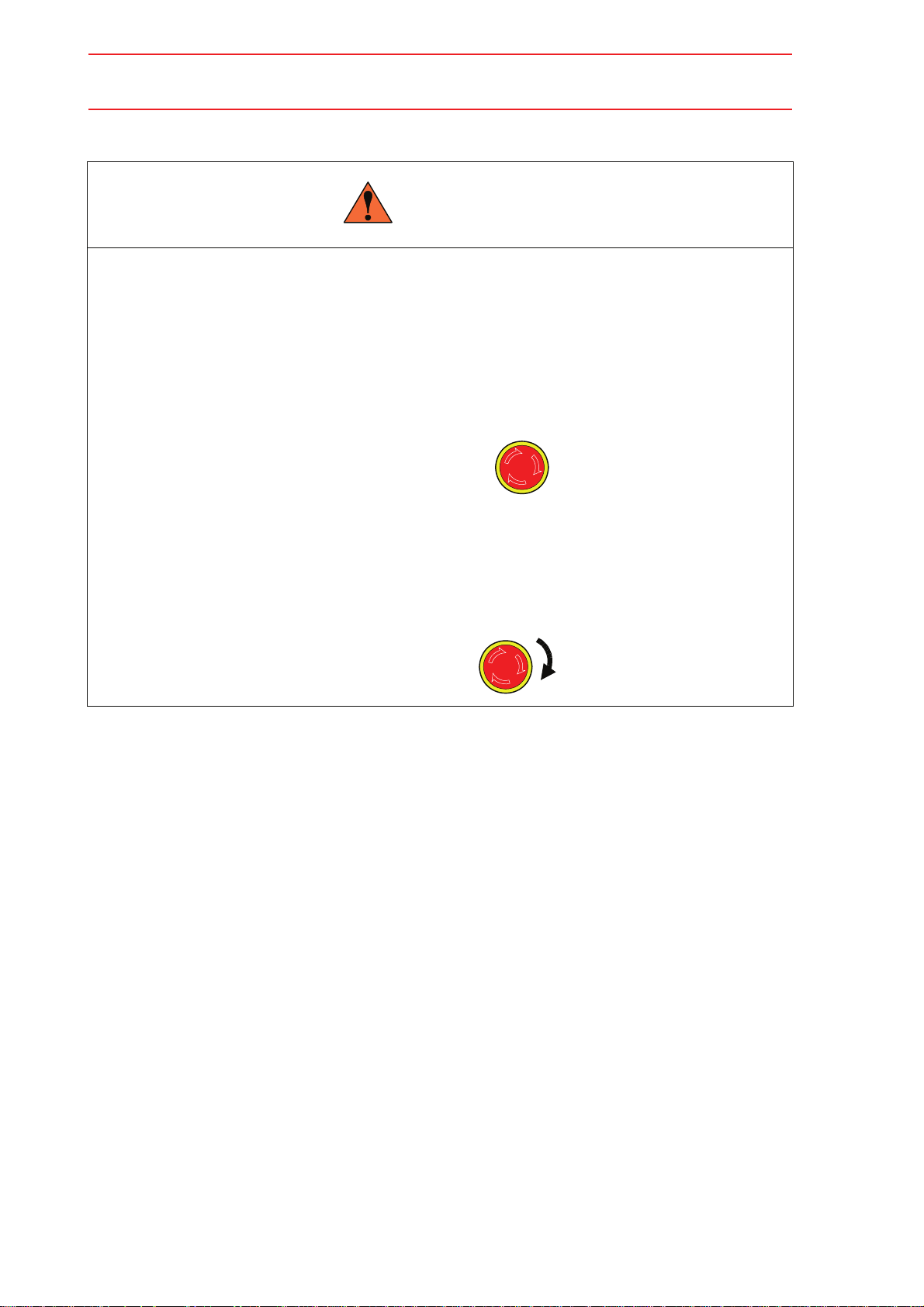
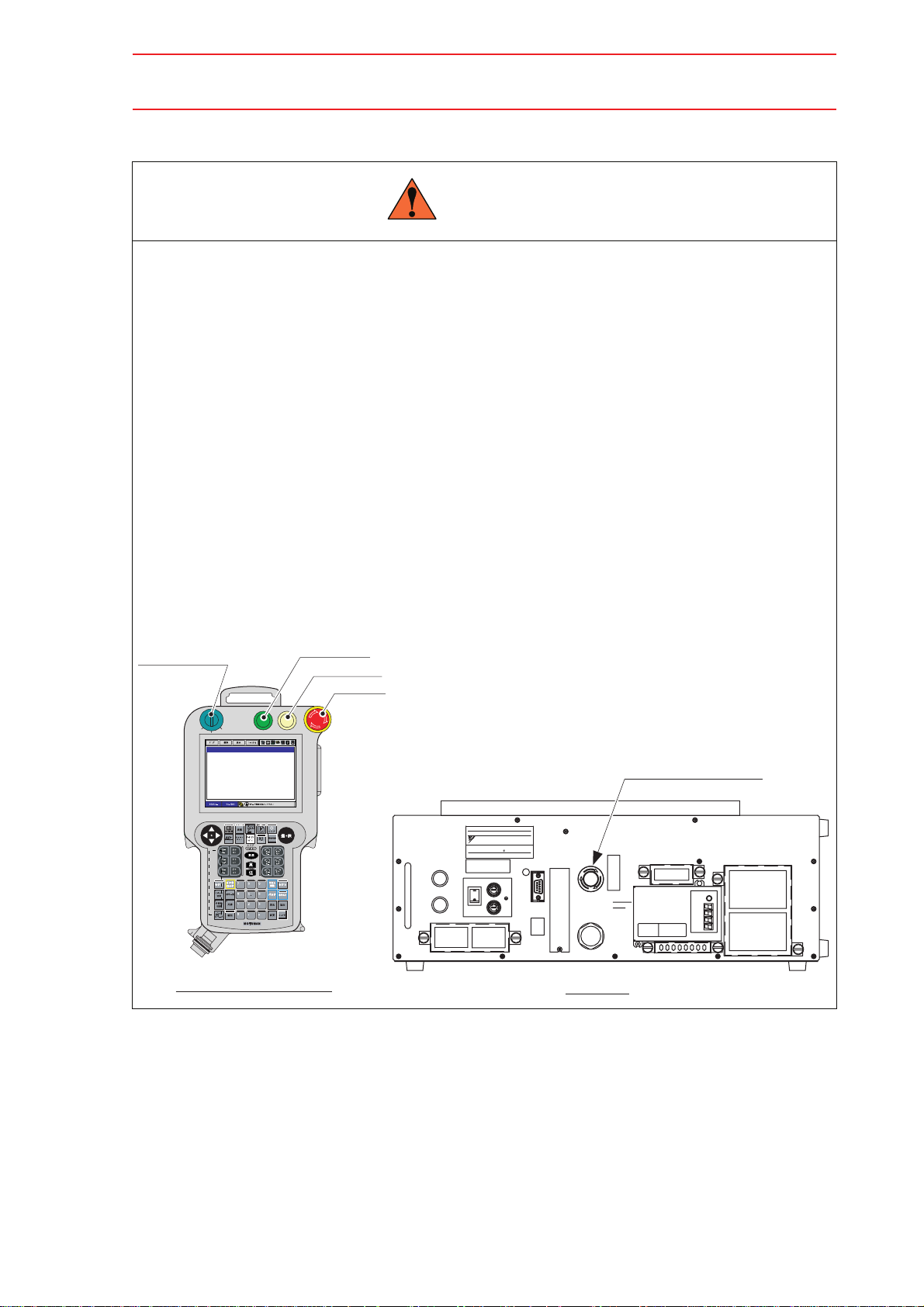
WARNING
• Before operating the manipulator , c hec k tha t servo power is turned OFF
when the emergency stop buttons on the front face of the NXC100 and
on the right side of the programming pendant are pressed.
When the servo power is turned OFF, the SERVO ON LED on the programming pendant is turned OFF.
Injury or damage to machinery may result if the emergency stop circuit cannot stop the
manipulator during an emergency. The manipulator should not be used if the emergency
stop buttons do not function.
Emergency Stop Button
• Once the emergency stop button is released, clear the cell of all items
which could interfere with the operation of the manipulator.
Then turn the servo power ON.
Injury may result from unintentional or unexpected manipulator motion.
TURN
Release of Emergency Stop
iv
HW0483547
Page 15
HW0483547
5/50
WARNING
• Observe the following precautions when performing teaching operations:
-Always follow the predetermined operating procedure.
-Ensure that you have a safe place to retreat in case of emergency.
Improper operation or unintended manipulator motion may result in injury.
• Confirm that no persons are present in the P-point maximum envelope of
the manipulator and that you are in a safe location before:
-Turing ON the robot system power.
-Moving the manipulator with the programming pendant.
-Running the system in the check mode.
-Performing automatic operations.
Injury may result if anyone enters the P-point maximum envelope of the manipulator during operation. Always press an emergency stop button immediately if there is a problem.
The emergency stop button is located on the right side of the programming pendant and
on the front face of the NXC100.
Mode selector switch
REMOTE
TEACH
PLAY
Programming pendant
Start button
Hold button
HOLDSTART
Emergency
stop button
DATE
SER NO.
44A220-011
TYPE
ERCR-NS00-A200
YASKAWA ELECTRIC CORPORATION
JAPAN
POWER SUPPLY
AC200/220V 50/60Hz 1 1 KVA
Approx mass.
16 Kg
NJ2520-2
ON (I)
F1
FU1
ON
SOURCE
FU2
OFF
OFF (O)
F2
Emergency stop button
3-2005
NJ2518-2
NJ2519-2
X52
SOURCE
X51
X31
BATTERY
FUSE
AC FUSE : F1,F2
15A / 250V
SLOW BLOW
I/O FUSE : F1,F2,F3,F4
3.15A / 250V
FAST BLOW
X81
NXC100
BAT
NXC100
v
HW0483547
Page 16
HW0483547
6/50
CAUTION
• Perform the following inspection procedures prior to conducting manipulator teaching. If problems are found, repair them immediately,
and be sure that all other necessary processing has been performed.
-Check for problems in movement of the manipulator and servo track.
-Check for damage to insulation and sheathing of external wires.
• Read and understand the Explanation of Warning Labels before operating the robot system.
• For safety, operate under the proper lighting.
Definition of Terms Used Often in This Manual
The MOTOMAN manipulator is the YASKAWA industrial robot product.
The manipulator usually consists of the controller, the programming pendant, and supply
cables.
In this manual, the equipment is designated as follows:
Equipment Manual Designation
NXC100 Controller NXC100
NXC100 Programming Pendant Programming Pendant
Cable between the Manipulator and the Controller Manipulator Cable
vi
HW0483547
Page 17

HW0483547
7/50
Explanation of Warning Labels
The following warning labels are attached to the manipulator.
Always follow the warnings on the labels.
Also, an identification label with important information is placed on the body of the manipulator. Prior to operating the manipulator, confirm the contents.
Nameplate
Nameplate
MOTOMAN
TYPE
PAYLOAD
ORDER NO.
SERIAL NO.
YASKAWA ELECTRIC CORPORAION JAPAN
Warning label B
Warning label A
Warning label B
Warning Label A:
WARNING
kg
MASS
DATE
kg
Moving parts
may cause
injury
Warning Label B:
WARNING
Do not enter
robot
work area.
vii
HW0483547
Page 18

8/50
1 Product Confirmation
1.1 Contents Confirmation . . . . . . . . . . . . . . . . . . . . . . . . . . . . .1-1
1.2 Order Number Confirmation . . . . . . . . . . . . . . . . . . . . . . . .1-2
2 Transporting
2.1 Transporting Method . . . . . . . . . . . . . . . . . . . . . . . . . . . . . . .2-2
2.1.1 Using a Crane. . . . . . . . . . . . . . . . . . . . . . . . . . . . . . . . . . . . . . 2-2
2.1.2 Using a Forklift . . . . . . . . . . . . . . . . . . . . . . . . . . . . . . . . . . . . . 2-3
3 Installation
3.1 Installation of Safeguarding . . . . . . . . . . . . . . . . . . . . . . . .3-2
HW0483547
3.2 Mounting Procedures for Manipulator Base. . . . . . . . .3-2
3.2.1 When the Manipulator and Mounting Fixture are Installed on a
Baseplate . . . . . . . . . . . . . . . . . . . . . . . . . . . . . . . . . . . . . . . . . 3-3
3.2.2 When the Manipulator is Mounted Directly on the Floor
without the Mounting Fixture. . . . . . . . . . . . . . . . . . . . . . . . . . . 3-4
3.3 Installation Method . . . . . . . . . . . . . . . . . . . . . . . . . . . . . . . . .3-5
3.4 Location. . . . . . . . . . . . . . . . . . . . . . . . . . . . . . . . . . . . . . . . . . . .3-6
4 Wiring
4.1 Grounding. . . . . . . . . . . . . . . . . . . . . . . . . . . . . . . . . . . . . . . . . .4-2
4.2 Manipulator Cable Connection . . . . . . . . . . . . . . . . . . . . . 4-3
4.2.1 Connection to the Manipulator . . . . . . . . . . . . . . . . . . . . . . . . . 4-3
4.2.2 Connection to the NXC100. . . . . . . . . . . . . . . . . . . . . . . . . . . . 4-3
5 Basic Specifications
5.1 Basic Specifications. . . . . . . . . . . . . . . . . . . . . . . . . . . . . . . .5-1
5.2 Part Names and Working Axes . . . . . . . . . . . . . . . . . . . . . 5-2
5.3 Manipulator Base Dimensions. . . . . . . . . . . . . . . . . . . . . .5-2
5.4 Dimensions and P-Point Maximum Envelope . . . . . . . 5-3
5.5 Special Interference Area . . . . . . . . . . . . . . . . . . . . . . . . . .5-4
5.6 B-Axis Operating Range. . . . . . . . . . . . . . . . . . . . . . . . . . . .5-5
5.7 Alterable Operating Range . . . . . . . . . . . . . . . . . . . . . . . . . 5-5
viii
HW0483547
Page 19

HW0483547
9/50
6 Allowable Load for Wrist Axis and Wrist Flange
6.1 Allowable Wrist Load . . . . . . . . . . . . . . . . . . . . . . . . . . . . . . 6-1
6.2 Wrist Flange. . . . . . . . . . . . . . . . . . . . . . . . . . . . . . . . . . . . . . . 6-2
7 System Application
7.1 Peripheral Equipment Mount. . . . . . . . . . . . . . . . . . . . . . . 7-1
7.2 Internal User I/O Wiring Harness and Air Lines . . . . 7-2
8 Electrical Equipment Specification
8.1 Internal Connections. . . . . . . . . . . . . . . . . . . . . . . . . . . . . . . 8-1
9 Maintenance and Inspection
9.1 Inspection Schedule . . . . . . . . . . . . . . . . . . . . . . . . . . . . . . . 9-1
9.2 Notes on Maintenance Procedures . . . . . . . . . . . . . . . . 9-5
9.2.1 Battery Pack Replacement . . . . . . . . . . . . . . . . . . . . . . . . . . . .9-5
9.2.2 Grease Replenishment for S-axis Speed Reducer . . . . . . . . . .9-7
Grease Replenishment (Refer to " Fig. 22 S-axis
Speed Reducer Diagram ".) . . . . . . . . . . . . . . . . . . . . . . . . .9-7
9.2.3 Grease Replenishment for L-axis Speed Reducer . . . . . . . . . .9-8
Grease Replenishment (Refer to " Fig. 23 L-axis
Speed Reducer Diagram ".) . . . . . . . . . . . . . . . . . . . . . . . . .9-8
9.2.4 Grease Replenishment for Speed Reducers of U- and R-axes.9-9
Grease Replenishment (Refer to " Fig. 24 UR-Axis Speed
Reducer Diagram ".) . . . . . . . . . . . . . . . . . . . . . . . . . . . . . . .9-9
9.2.5 Grease Replenishment for Speed Reducers of
B- and T-axes, and T-axis Gear . . . . . . . . . . . . . . . . . . . . . . .9-10
Grease Replenishment (Refer to " Fig. 25 BT-Axis
Speed Reducer and T-axis Gear Diagram ".) . . . . . . . . . . .9-10
9.2.6 Notes for Maintenance . . . . . . . . . . . . . . . . . . . . . . . . . . . . . .9-11
Battery Pack Connection. . . . . . . . . . . . . . . . . . . . . . . . . . .9-11
10 Recommended Spare Parts
ix
HW0483547
Page 20
HW0483547
10/50
1.1 Contents Confirmation
1 Product Confirmation
CAUTION
• Confirm that the manipulator and the NXC100 have the same order number. Special care must be taken when more than one manipulator is to
be installed.
If the numbers do not match, manipulators may not perform as expected and cause injury
or damage.
1.1 Contents Confirmation
Confirm the contents of the delivery when the product arrives.
Standard delivery includes the following four items (information for the content of optional
goods is given separately):
• Manipulator
• NXC100
• Programming pendant
• Manipulator cable (2 cables, between the manipulator and NXC100)
1-1
HW0483547
Page 21
HW0483547
11/50
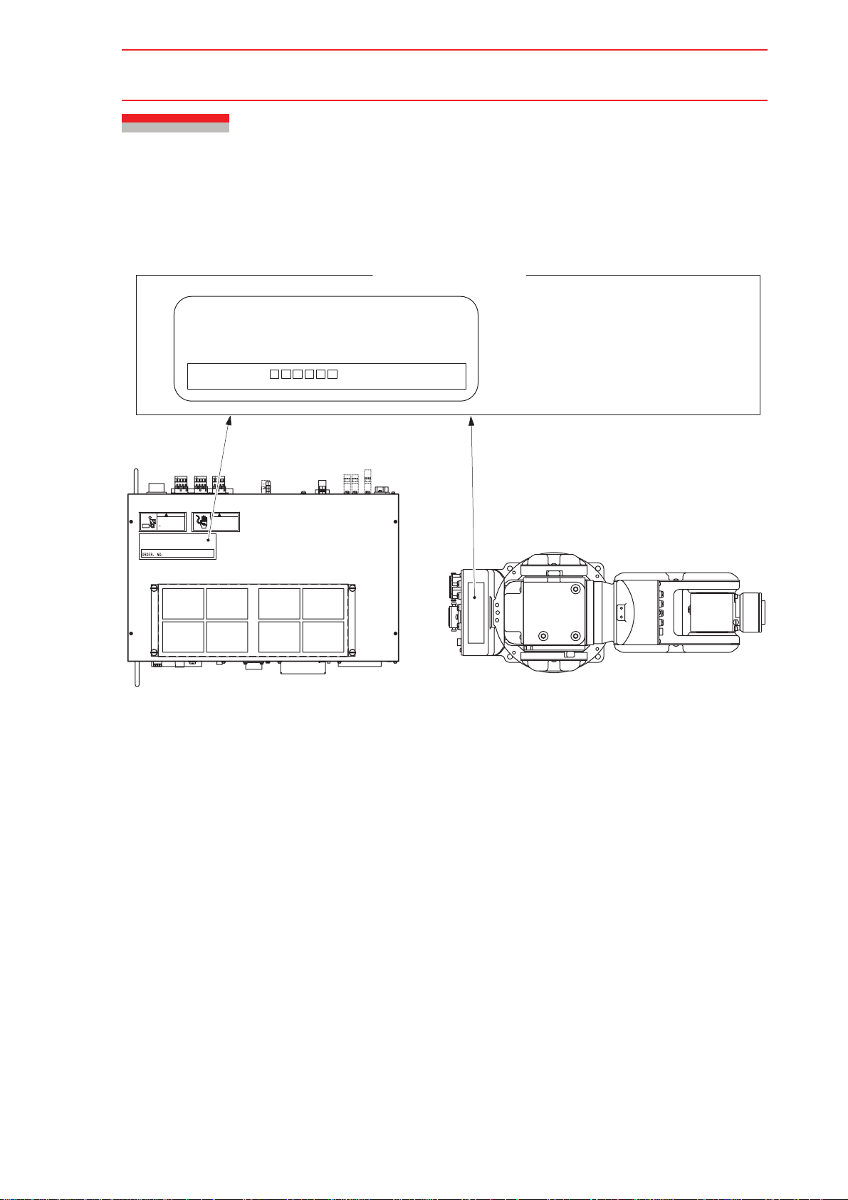
1.2 Order Number Confirmation
1.2 Order Number Confirmation
Check that the order number of the manipulator corresponds to the NXC100. The order
number is located on a label as shown below.
Label (Enlarged View)
THE MANIPULATOR AND THE CONTROLLER
SHOULD HAVE SAME ORDER NUMBER.
ORDER NO.
WARNING
HEAVY OBJECT
Can cause muscle strain or
back injury. Use lifting aids
proper lifting technjques
when removing or replacing
WARNING
HAZAARDOUS VOLTAGE
208/110 VAC PRESENT
Contact may cause
electric shock or burn
Turn off and lock out
system power before servicing
(a) NXC100 (Top View)
Fig. 1 Location of Order Number Labels
Check that the manipulator
and the NXC100 have the
same order number.
(b) Manipulator (Top View)
1-2
HW0483547
Page 22
HW0483547
12/50
2 Transporting
CAUTION
• Sling and crane or forklift operations must be performed by authorized
personnel only.
Failure to observe this caution may result in injury or damage.
• Avoid excessive vibration or shock during transportation.
The system consists of precision components, so failure to observe this caution may
adversely affect performance.
NOTE
• Be sure to mount two eyebolts and check that the eyebolts are securely fastened before
transporting the manipulator.
• The mass of the manipulator is approximately 27 kg. Use a wire rope strong enough to
withstand the mass.
• Attached eyebolts are designed to support the manipulator mass. Do not use them for
anything other than transporting the manipulator.
• Avoid exerting external force on the arm or motor unit when transporting the manipulator.
Use caution when using transporting equipment other than a crane or forklift to avoid
injury.
2-1
HW0483547
Page 23

HW0483547
13/50
2.1 Transporting Method
2.1 Transporting Method
2.1.1 Using a Crane
As a rule, when removing the manipulator from the package and moving it, a crane should be
used. The manipulator should be lifted using wire rope threaded through attached eyebolts.
Be sure the manipulator is fixed with shipping bolts and brackets before transportation, and lift
it in the posture as shown in " Fig. 2 Transporting Position ".
Eyebolt M8 (2 eyebolts)
(Delivered with the manipulator)
NOTE
Fig. 2 Transporting Position
Before turning ON the power, check to be sure that the eyebolts have been removed. The
eyebolts then must be stored for future use, in the event that the manipulator must be
moved by a crane again.
2-2
HW0483547
Page 24

HW0483547
14/50
2.1 Transporting Method
2.1.2 Using a Forklift
When using a forklift, the manipulator should be fixed on a pallet as shown in " Fig. 3 Using a
Forklift ". Insert claws under the pallet and lift it. The pallet must be strong enough to support
the manipulator. Transportation of the manipulator must be performed slowly in order to avoid
overturning or slippage.
Bolts M8 (4 bolts)
Pallet
Forklift claw entry
Fig. 3 Using a Forklift
2-3
HW0483547
Page 25

HW0483547
15/50
3 Installation
WARNING
• Install the safeguarding.
Failure to observe this warning may result in injury or damage.
• Install the manipulator in a location where the manipulator’s tool or the
workpiece held by the manipulator will not reach the wall, safeguarding,
or NXC100 when the arm is fully extended.
Failure to observe this warning may result in injury or damage.
• Do not start the manipulator or even turn ON the power before it is
firmly anchored.
The manipulator may overturn and cause injury or damage.
• When mounting the manipulator on the ceiling or wall, the base section
must have sufficient strength and rigidity to support the mass of the
manipulator. Also, it is necessary to consider countermeasures to prevent the manipulator from falling.
Failure to observe these warning may result in injury or damage.
CAUTION
• Do not install or operate the manipulator that is damaged or lacks parts.
Failure to observe this caution may cause injury or damage.
• Before turning ON the power, check to be sure that the eyebolts
explained in "2.1.1 Using a Crane" are removed.
Failure to observe this caution may result in damage to the driving parts.
3-1
HW0483547
Page 26

HW0483547
16/50
3.1 Installation of Safeguarding
3.1 Installation of Safeguarding
To insure safety, be sure to install the safeguarding. It prevents unforeseen accidents with
personnel and damage to equipment. The following is quoted for your information and
guidance.
Responsibility for Safeguarding (ISO10218)
The user of a manipulator or robot system shall ensure that the safeguarding is provided and
used in accordance with Sections 6, 7, and 8 of this standard. The means and degree of
safeguarding, including any redundancies, shall correspond directly to the type and level of
hazard presented by the robot system consistent with the robot application. Safeguarding may
include but not be limited to safeguarding devices, barriers, interlock barriers, perimeter
guarding, awareness barriers, and awareness signals.
3.2 Mounting Procedures for Manipulator Base
The manipulator should be firmly mounted on a baseplate or foundation strong enough to
support the manipulator and withstand repulsion forces during acceleration and deceleration.
Refer to "Table. 1 Maximum Repulsion Forces of the Manipulator" and " Table. 2 Endurance
Torque in Operation " to construct a solid foundation with the appropriate thickness to
withstand maximum repulsion forces of the manipulator.
A manipulator base flatness must be kept at 0.5 mm or less: insufficient flatness of installation
surface may deform the manipulator shape and affect its functional abilities. Mount the
manipulator base as described in "3.2.1 When the Manipulator and Mounting Fixture are
Installed on a Baseplate" or "3.2.2 When the Manipulator is Mounted Directly on the Floor
without the Mounting Fixture".
Table. 1 Maximum Repulsion Forces of the Manipulator
Horizontal rotating maximum torque
(S-axis moving direction)
Vertical rotating maximum torque
(LU-axes moving direction)
294 Nm
(30 kgfm)
627 Nm
(64 kgfm)
Table. 2 Endurance Torque in Operation
Endurance torque in horizontal operation
(S-axis moving direction)
Endurance torque in vertical operation
(LU-axes moving direction)
3-2
59 Nm
(6 kgfm)
194 Nm
(20 kgfm)
HW0483547
Page 27

HW0483547
25 or
more
17/50
3.2 Mounting Procedures for Manipulator Base
3.2.1 When the Manipulator and Mounting Fixture are
Installed on a Baseplate
For the first process, anchor the baseplate firmly to the ground. The baseplate should be rugged and durable to prevent shifting of the manipulator or the mounting fixture. It is recommended to prepare a baseplate in 25 mm in thickness, and anchor bolts in M8 or larger size.
Next, fix the manipulator base to the baseplate. The manipulator base is tapped for four
mounting holes; securely fix the manipulator base to the baseplate with four hexagon socket
head screws M8 (35 mm long is recommended) and tighten the screw to a tightening torque of
24.5 N
that they will not work loose during the operation.
See "Fig. 4 Manipulator Installation Example" for the method.
xm (2.5 kgxm). Tighten the hexagon socket head cap screws and anchor bolts firmly so
Hexagon socket head cap screw M8
(4 screws),
Tightening torque: 24.5 Nxm (2.5 kgfxm)
Manipulator base
155
50
145
78±0.1
85
+0.012
6 dia. (reference hole)
0
50±0.1
50
Baseplate
150
170
12
25 or
more
Anchor bolt (M8 or larger)
Baseplate
±0.1
88
Spring washer
Washer
Manipulator base
Baseplate
150
170
88
9 dia. mounting hole (4 places)
±0.1
Units: mm
Fig. 4 Manipulator Installation Example
3-3
HW0483547
Page 28

HW0483547
18/50
3.2 Mounting Procedures for Manipulator Base
3.2.2 When the Manipulator is Mounted Directly on the
Floor without the Mounting Fixture
The floor should be strong enough to support the manipulator. Construct a solid foundation
with the appropriate thickness to withstand maximum repulsion forces of the manipulator as
shown in "Table. 1 Maximum Repulsion Forces of the Manipulator". When there is a concrete
thickness (floor) of 150 mm or more, the base of the manipulator can be fixed directly to the
floor with M8 anchor bolts. (The concrete breaking-stress should be 250 kg/cm
Before mounting the manipulator, check that the floor is level and that all cracks, etc. are
repaired. Any thickness less than 150 mm is insufficient for mounting, even if the floor is concrete.
2
or more.)
Anchor bolts M8 (4 places)
Fig. 5 Direct Mounting on the Floor
Concrete floor
45 or more
150 or more
Units: mm
3-4
HW0483547
Page 29

HW0483547
19/50
3.3 Installation Method
3.3 Installation Method
The manipulator can be mounted in three different ways: floor-mounted (standard), wallmounted, and ceiling-mounted types are available. For wall- and ceiling-mounted types, the
three points listed below are different from the floor-mounted types.
1. For the wall-mounted type, the S-axis specification is different from the ceiling- and
floor-mounted types. (The specification is changed before shipment.)
• The S-axis operating range for the wall-mounted type must be ±25
2. For the ceiling- and wall-mounted types, four hexagon socket head cap screws M8
2
(tensile strength: 1200 N/mm
to fix the manipulator base. Use a torque of 24.5 N
or more) (35 mm long is recommended) should be used
xm in tightening the screws.
°.
3. For the ceiling- and wall-mounted types, take appropriate measures to avoid the falling
of manipulator in case of emergency. See "Fig. 6 Precaution to Prevent the Manipulator from Falling" for details.
Support to prevent the manipulator from fall
NOTE
Manipulator base
Fig. 6 Precaution to Prevent the Manipulator from Falling
If the manipulator is to be wall mounted or ceiling mounted, inform Yaskawa of the matter
when placing an order. And also, make sure to contact Yaskawa representative (listed on
the back cover of this instruction manual) for a wall/ceiling installation on side.
Hexagon socket head cap screw M8 (4 places)
Tightening torque: 24.5 N
Spring washer
Washer
x
m (2.5 kgfxm)
3-5
HW0483547
Page 30

HW0483547
20/50
3.4 Location
3.4 Location
When the manipulator is installed, it is necessary to satisfy the undermentioned environmental
conditions:
• Ambient temperature: 0° to +40°C (ambient temperature)
• Humidity: 20 to 80%RH (no moisture, at constant temperature)
• Free from dust, soot, or water
• Free from corrosive gases or liquids, or explosive gases
• Free from excessive impact or vibration (vibration acceleration: 4.9 m/s
• Free from large electrical noise (plasma)
• The flatness for installation is 0.5 mm or less.
2
[0.5 G] or less)
3-6
HW0483547
Page 31

HW0483547
21/50
4 Wiring
WARNING
• Ground resistance must be 100 Ω or less.
Failure to observe this warning may result in fire or electric shock.
• Before wiring, make sure to turn the primary power supply OFF, and put
up a warning sign. (ex. DO NOT TURN THE POWER ON.)
Failure to observe this warning may result in fire or electric shock.
CAUTION
• Wiring must be performed by authorized or certified personnel.
Failure to observe this caution may result in fire or electric shock.
• Do not cover the cable or allow it to tangle. Keep the cable as straight
as possible.
Failure to observe this caution may result in preventing heat of the cable from being discharged.
4-1
HW0483547
Page 32

HW0483547
22/50
4.1 Grounding
4.1 Grounding
Follow the local regulations and electrical installation standards for grounding. The recommended grounding wire size is 5.5 mm
For grounding, connect the ground wire directly to the manipulator as shown in "Fig. 7
Grounding Method".
• Do not use this line in common with other ground lines or grounding electrodes for other
NOTE
electric power, motor power, welding devices, etc.
• Where metal ducts, metallic conduits, or distributing racks are used for cable laying,
ground in accordance with Electric Equipment Technical Standards.
2
at minimum.
Bolt M6 (for grounding)
Delivered with the manipulator
Fig. 7 Grounding Method
Section A-A’
A
A’
4-2
HW0483547
Page 33

HW0483547
23/50
4.2 Manipulator Cable Connection
4.2 Manipulator Cable Connection
There are two manipulator cables; an encoder cable for detection (1BC) and power cable
(2BC). (See "Fig. 8 Manipulator Cables (1BC and 2BC)".) Connect these cables respectively
to the connectors at the manipulator connector base and the NXC100. Refer to "Fig. 9 (a)
Manipulator Cable Connectors (Manipulator Side)" and "Fig. 9 (b) Manipulator Cable
Connectors (NXC100 Side)".
4.2.1 Connection to the Manipulator
Before connecting the manipulator cables to the manipulator, verify the numbers on both the
cables and the connectors of manipulator connector base. Connect 2BC first, and then 1BC.
Insert the cables and lower each lever until it clicks.
4.2.2 Connection to the NXC100
Before connecting the manipulator cables to the NXC100, verify the numbers on both the
cables and the NXC100 connectors. Connect 2BC first to the connector X21 of NXC100, then
1BC to the connector X11 of NXC100. Insert the cables and lower each lever until it clicks.
The NXC100 Side
Encoder Cable 1BC
The NXC100 Side
The Manipulator Side
1BC
1BC
The Manipulator Side
2BC
2BC
Power Cable 2BC
Fig. 8 Manipulator Cables (1BC and 2BC)
4-3
HW0483547
Page 34

4.2 Manipulator Cable Connection
24/50
Fig. 9 (a) Manipulator Cable Connectors (Manipulator Side)
HW0483547
2BC
1BC
3BC
Connector details
(Manipulator side)
X11
X72
X11
X21
X12
X64-X63
FAN3
X21
FAN2
X54
X53
X55
X71
X62
Connector details
PPESP PPESP
(NXC100 side)
Fig. 9 (b) Manipulator Cable Connectors (NXC100 Side)
4-4
HW0483547
Page 35

HW0483547
25/50
5 Basic Specifications
5.1 Basic Specifications
5.1 Basic Specifications
Table. 3 Basic Specifications
Item
Model
Configuration Vertically Articulated
Degree of Freedom 6
Payload 3 kg
*2
S-axis (turning)
L-axis (lower arm) +90°, -85°
U-axis (upper arm) +260°, -105°
R-axis (wrist roll) ±170°
B-axis (wrist pitch/yaw) ±120°
T-axis (wrist twist) ±360°
S-axis 3.49 rad/s, 200
L-axis 2.62 rad/s, 150
U-axis 3.32 rad/s, 190
R-axis 5.24 rad/s, 300
B-axis 5.24 rad/s, 300
T-axis 7.33 rad/s, 420
R-axis 5.39 Nm (0.55 kgfm)
B-axis 5.39 N
T-axis 2.94 N
R-axis
B-axis
T-axis
Temperature 0 to 40
Humidity 20 to 80% RH (at constant temperature)
Vibration Acceleration
Others
Range of
Motion
Maximum
Speed
Allowable
Moment
Allowable
Inertia
2
(GD
/4)
Ambient
Conditions
Repeatability
*3
*3
Approx. Mass 27 kg
Power Requirements 0.5 kVA
*1
MOTOMAN-HP3J
YR-HP3J-J00
±0.03 mm
±160°
°/s
°/s
°/s
°/s
°/s
°/s
m (0.55 kgfm)
m (0.3 kgfm)
2
m
0.1 kg
m
m
°C
2
2
2
(0.5G)
0.1 kg
0.03 kg
Less than 4.9 m/s
• Free from corrosive gas or liquid, or explosive
gas.
• Free from water, oil, or dust.
• Free from excessive electrical noise (plasma).
*1 SI units are used in this table. However, gravitational unit is used in ( ).
*2 Conformed to ISO9283
*3 Refer to " 6.1 Allowable Wrist Load " for details on the allowable moment of inertia.
5-1
HW0483547
Page 36

5.2 Part Names and Working Axes
26/50
5.2 Part Names and Working Axes
HW0483547
Upper arm
(U-arm)
Lower arm
(L-arm)
U
U
R
R
L L
Rotary head
(S-head)
Base
S
S
Fig. 10 Part Names and Working Axes
5.3 Manipulator Base Dimensions
Wrist
B
T
T
B
155
50
145
A
View A
Fig. 11 Manipulator Base Dimensions
78±0.1
170
150
85
+0.012
0
6 dia. hole (reference hole)
50±0.1
50
150
9 dia. mounting hole (4 places)
±0.1
88
±0.1
88
170
Units: mm
5-2
HW0483547
Page 37

HW0483547
27/50
5.4 Dimensions and P-Point Maximum Envelope
5.4 Dimensions and P-Point Maximum Envelope
160
659
79
30
290 260
133
74
42
0
57
(*1)
531
372
389
260
337
276
229
R104
85
40
160
R188
R532
105
381
532
822
583
474
P-point maximum
envelope
193
47
18
0
(*2)
95
99.5
68
99.5
68
21
270
90
189
158
188
204
55
90
P-point
219
0
0
(*1) Shows the LU-axes working envelope within the range of S-axis motion: -40 to 40 .
(*2) Shows the LU-axes working envelope within the range of S-axis motion: -160 to 125 or 125 to 160 .
Refer to " 5.5 Special Interference Area" for details.
Fig. 12 (a) Dimensions and P-Point Maximum Envelope
5-3
HW0483547
Page 38

5.5 Special Interference Area
28/50
5.5 Special Interference Area
Shows the LU-axes working envelope within the range of S-axis motion: -160 to 125 or 125 to 160 .
35
35
HW0483547
125
125
193
47
0
381
Shows the LU-axes working envelope within the range of S-axis motion: -40 to 40 .
158
204
U-axis does not move the S-axis is in area
of the slash part in above figure.
189
0
40
40
133
74
0
389
337
U-axis does not move the S-axis is in area
of the slash part in above figure.
0
Fig. 12 (b) Special Interference Area (LU interference)
5-4
HW0483547
Page 39

HW0483547
29/50
5.6 B-Axis Operating Range
5.6 B-Axis Operating Range
" Fig. 13 B-axis Operating Range " shows the operating range of the B-axis maintaining a
constant angle to the center of U-axis.
B-axis rotation center
U-axis rotation center
120°
120°
Wrist
U-axis rotation center
S-axis rotation center
Fig. 13 B-axis Operating Range
5.7 Alterable Operating Range
The operating range of S-axis can be altered according to the operating conditions as shown
in "Table. 4 S-Axis Operating Range". If alteration is necessary, contact your Yaskawa
representative in advance.
Table. 4 S-Axis Operating Range
Item Specifications
±160° (standard)
S-Axis
Operating
Range
±120°
±90°
±60°
±25°
NOTE
If readjustment (alteration of the S-axis operating range) is necessary, contact your
Yaskawa representative.
5-5
HW0483547
Page 40

HW0483547
30/50
6.1 Allowable Wrist Load
6 Allowable Load for Wrist Axis and Wrist
Flange
6.1 Allowable Wrist Load
The allowable wrist load is up to 3 kg. If force is applied to the wrist instead of the load, force
on R-, B-, and T-axes should be within the value shown in " Table. 5 Allowable Moment and
Inertia ". Contact your Yaskawa representative for further information or assistance.
Table. 5 Allowable Moment and Inertia
Axis
R-axis
B-axis
T-axis
*1
( ): Gravitational unit
Moment N•m (kgf•m)
5.39 (0.55)
5.39 (0.55)
2.94 (0.3)
*1
Inertia kg•m
0.1
0.1
0.03
2
When the volume load is small, refer to the moment arm rating shown in " Fig. 14 Moment
Arm Rating ".
The allowable inertia is calculated when the moment is at the maximum. Contact your
Yaskawa representative when only load inertia, or load moment is small and inertia is large.
Also, when the load is combined as a force but a mass, contact your Yaskawa representative.
LT (mm)
200
100
3kg
100
1.5kg
200
RT-axis rotation center
L
(mm)
B
300
P-point
100
200
LT (mm)
Fig. 14 Moment Arm Rating
B-axis rotation center
6-1
HW0483547
Page 41

HW0483547
31/50
6.2 Wrist Flange
6.2 Wrist Flange
The wrist flange dimensions are shown in " Fig. 15 Wrist Flange ". In order to see the
alignment marks, it is recommended that the attachment be mounted inside the fitting. Fitting
depth of inside and outside fittings must be 5 mm or less.
Tapped hole M5 (4 places)
5 (fitting depth)
(Depth: 9) (Pitch: 0.8)
NOTE
45°
Units: mm
5 (fitting depth)
+0.013
0
20 dia.
0
-0.016
PCD31.5
40 dia.
5 dia. hole
(Depth: 7)
+0.012
0
Fig. 15 Wrist Flange
• Wash off anti-corrosive paint (yellow color) on the wrist flange surface with thinner or light
oil before mounting the tools.
6-2
HW0483547
Page 42

HW0483547
32/50
7.1 Peripheral Equipment Mount
7 System Application
7.1 Peripheral Equipment Mount
The peripheral equipment mount is on the upper arm for easier installation of the user’s
system application as shown in " Fig. 16 Installing Peripheral Equipment Mounts ". When
peripheral equipment is attached to the U-axis, the following conditions should be observed.
3718
Tapped hole M8 (3 places)
(Pitch: 1.25) (Depth: 16)
Fig. 16 Installing Peripheral Equipment Mounts
80
Units: mm
7-1
HW0483547
Page 43

HW0483547
33/50
7.2 Internal User I/O Wiring Harness and Air Lines
7.2 Internal User I/O Wiring Harness and Air Lines
Internal user I/O wiring harness (0.2 mm2 x 10 wires) and four air lines are used in the
manipulator for the drives of the peripheral devices mounted on the upper arm as shown in "
Fig. 17 Connectors for Internal User I/O Wiring Harness and Air Lines ".
The connector pins (1 to 10) are assigned as shown in " Fig. 17 Connectors for Internal User
I/O Wiring Harness and Air Lines ". Wiring must be performed by users, following the
conditions below:
• The allowable current for cables: 2.5 A or less for each cable
• The maximum pressure for the air line: 490 kPa (5 kgf/cm
(the inside diameter: 2.5 mm)
2
) or less
Connector for internal user I/O wiring harness:
HR10A-10R-12S (socket connector).
Prepare pin connector: HR10A-10P-12P*HIROSE*.
B
Details of the Connector Pin Numbers
Internal user I/O wiring harness: 0.2 mm2, 10 wires
Pins Used
1
2
3
4
5
6
7
8
9
10
9
8
7
10
12
6
5
4 Exhaust ports:
Tapped hole M5 with pipe plug
A
View A
4 Air inlets:
Tapped hole M5 with pipe plug
2BC
1BC
1
2
3
11
4
View B
Connector for internal user I/O wiring harness:
HR10A-10R-12P (pin connector).
Prepare socket connector: HR10A-10P-12S*HIROSE*.
3BC
Fig. 17 Connectors for Internal User I/O Wiring Harness and Air Lines
The same pin number (1-10) of two connectors is connected by the lead wire of single
0.2 mm
2
.
7-2
HW0483547
Page 44

HW0483547
34/50
8.1 Internal Connections
8 Electrical Equipment Specification
8.1 Internal Connections
High reliability connectors which can be easily put on and removed are used with each
connector part. For the numbers, types, and locations of connectors, see " Fig. 18 Location
Connectors " and " Table. 6 List of Connector Types ". Diagrams for internal connections
of the manipulator are shown in " Fig. 19 (a) Internal Connection Diagram " and " Fig. 19 (b)
Internal Connection Diagram ".
U-arm
Connector for internal user I/O wiring harness
Connector base
Connector for internal user I/O wiring harness
Fig. 18 Location Connectors
Table. 6 List of Connector Types
Name Type of Connector
Connector for internal user I/O
wiring harness on connector base
Connector for internal user I/O
wiring harness on U-arm
HR10A-10R-12P
(HR10A-10P-12S: Optional)
HR10A-10R-12S
(HR10A-10P-12P: Optional)
8-1
HW0483547
Page 45

HW0483547
35/50
NXC100
1BC(10X4)
8.1 Internal Connections
1
0BT
0BAT11
BAT
2
BAT11
0BT
3
0BAT12
BAT12
4
BAT
0BT
5
0BAT21
BAT
6
BAT21
0BT
7
0BAT22
BAT
8
BAT22
1
2
3
4
5
6
7
8
1BC(10X4)
+24V
12
52
13
53
6
46
1
7
47
2
8
48
3
9
49
41
10
50
42
11
51
43
CN1-5
CN1-4
CN1-10
CN1-9
CN1-1
CN1-2
CN1-3
CN1-6
CN1-7
CN1-8
CN2-1
CN2-2
CN2-3
CN2-6
CN2-7
CN2-8
CN3-1
CN3-2
CN3-3
CN3-6
CN3-7
CN3-8
0V
+24V
0V
SPG+1
SPG-1
FG1
SPG+2
SPG-2
FG2
SPG+3
SPG-3
FG3
SPG+4
SPG-4
FG4
SPG+5
SPG-5
FG5
SPG+6
SPG-6
FG6
1
3
2
4
17
0BAT1
18
BAT1
0BAT2
19
BAT2
20
21
22
23
24
25
0BAT4
26
BAT4
27
0BAT5
28
BAT5
29
30
31
32
1
PG0V1
2
PG5V1
3
PG0V2
4
PG5V2
5
PG0V3
6
PG5V3
7
PG0V4
8
PG5V4
9
PG0V5
10
PG5V5
11
PG0V6
12
PG5V6
13
14
15
16
P
P
P
Note:
The figure below shows the internal connection diagram for MOTOMAN-HP3J.
No.1CN
No.2CN
P
P
P
P
P
1CN-1
2CN-1
DATA+1
DATA-1-2
BAT1
-3
OBT1
-4
+5V1
0V1
-2
FG1
-3
OBT
BAT
No.3CN
P
No.4CN
P
No.5CN
No.6CN
P
P
P
P
3CN-1
4CN-1
5CN-1
6CN-1
-2
-3
-4
-2
-3
-2
-3
-4
-2
-3
No.7CN
7CN-1
8CN-1
No.8CN
DATA+2
DATA-2
BAT2
OBT2
+5V2
0V2
FG2
OBT
BAT
DATA+3
DATA-3
BAT3
OBT3
+5V3
0V3
FG3
OBT
BAT
DATA+4
-2
DATA-4
BAT4
-3
OBT4
-4
+5V4
0V4
-2
FG4
-3
OBT
BAT
S-axis
PG
PG
L-axis
PG
U-axis
For lamp (Option)
PG R-axis
No.9CN
9CN-1
P
P
P
P
P
P
No.10CN
No.11CN
P
No.12CN
-2
-3
-4
10CN-1
-2
-3
11CN-1
-2 DATA-6
-3
-4
12CN-1
-2
-3
DATA+5
DATA-5
BAT5
OBT5
+5V5
0V5
FG5
OBT
BAT
DATA+6
BAT6
OBT6
+5V6
0V6
FG6
OBT
BAT
B-axis
PG
T-axis
PG
CN4-1
CN4-6
CN4-3
+24V
LB1
BC2
E
37
77
32
33
34
35
36
76
E
Fig. 19 (a) Internal Connection Diagram
8-2
HW0483547
Page 46

8.1 Internal Connections
36/50
HW0483547
E
Base
E
2BC(6X6)
3BC
3BC-1
-2
-3
-4
-5
-6
-7
-8
-9
-10
1
2
3
4
5
6
7
8
9
10
P
P
P
P
P
3BC
1
2
3
4
5
6
7
8
9
10
3BC-1
-2
-3
-4
-5
-6
-7
-8
-9
-10
For spare (X)
2BC(6X6)
C5
D5
E5
A4
B4
A1
A2
A3
B1
B2
B3
C1
C2
C3
D1
D2
D3
E1
E2
E3
A5
A6
B6
C4
D4
E4
C6
E6
D6
CN1-1
CN1-2
CN1-3
CN1-4
CN1-5
CN2-1
CN2-2
CN2-3
CN2-4
CN2-5
CN2-6
CN3-4
CN3-5
CN3-6
CN4-1
CN4-2
CN4-3
CN4-4
CN4-5
CN4-6
CN5-1
CN5-2
CN5-3
CN5-4
CN5-5
CN5-6
CN6-1
CN6-2
CN6-3
CN6-4
CN6-5
CN6-6
E
BA1
BA2
BB1
ME1
ME2
MU1
MV1
MW1
MU2
MV2
MW2
MU3
MV3
MW3
MU4
MV4
MW4
MU5
MV5
MW5
MU6
MV6
MW6
ME3
ME4
ME5
ME6
BA3
BB4
BA4
BA5
BA6
No.14CN
No.13CN
13CN-1
14CN-1
MU1
MV1
-2
MW1
-3
ME1
-4
BA1
BB1
-2
No.16CN
No.18CN
No.15CN
15CN-1
16CN-1
No.17CN
17CN-1
18CN-1
No.20CN
MU2
MV2
-2
MW2
-3
ME2
-4
BA2
BB2
-2
MU3
MV3
-2
MW3
-3
ME3
-4
BA3
BB3
-2
No.19CN
20CN-1
19CN-1
-2
-3
-4
-2
No.22CN
No.24CN
MU4
MV4
MW4
ME4
BA4
BB4
No.21CN
No.23CN
SM
YB
SM
YB
SM
YB
21CN-1
22CN-1
23CN-1
24CN-1
S-axis
L-axis
U-axis
R-axis
SM
YB
MU5
MV5
-2
MW5
-3
ME5
-4
BA5
BB5
-2
MU6
MV6
-2
MW6
-3
ME6
-4
BA6
BB6
-2
SM
YB
SM
YB
B-axis
T-axis
PE
Fig. 19 (b) Internal Connection Diagram
8-3
HW0483547
Page 47

HW0483547
37/50
9.1 Inspection Schedule
9 Maintenance and Inspection
WARNING
• Before maintenance or inspection, be sure to turn the main power supply OFF, and put up a warning sign. (ex. DO NOT TURN THE POWER ON.)
Failure to observe this warning may result in electric shock or injury.
CAUTION
• Maintenance and inspection must be performed by specified personnel.
Failure to observe this caution may result in electric shock or injury.
• For disassembly or repair, contact your Yaskawa representative.
• Do not remove the motor or release the brake.
Failure to observe this caution may result in injury from unexpected turning of the manipulator’s arm.
• The battery pack must be connected before removing detection connector when maintenance and inspection.
Failure to observe this caution may result in the loss of home position data.
9.1 Inspection Schedule
Proper inspections are essential not only to assure that the mechanism will be able to function
for a long period, but also to prevent malfunctions and assure safe operation. Inspection
intervals are classified into six levels. Conduct periodical inspections according to the
inspection schedule in " Table. 7 Inspection Items ".
In " Table. 7 Inspection Items ", the inspection items are categorized by three types of
operations: operations which can be performed by personnel authorized of the user,
operations which can be performed by personnel being trained, and operations which can be
performed by service company personnel. Only specified personnel are to do the inspection
work.
9-1
HW0483547
Page 48

9.1 Inspection Schedule
38/50
HW0483547
NOTE
Items
Working area
and whole exte-
c
rior of manipulator
LU-axis joint
d
Manipulator
base
e
mounting bolts
Cover mounting
f
screws
• The inspection interval must be based on the servo power supply ON time.
Table. 7 Inspection Items
Schedule
*4
Daily
1000
H
Cycle
6000
H
Cycle
12000
H
Cycle
24000H36000
{
{
{
{
H
Method
Visual
Visual
Wrench
Phillips
screw-
driver,
wrench
Operation
Clean the working
area if dust or spatter
is present.
Check for damage
and exterior cracks.
Check for grease
*5
leakage.
Tighten loose bolts.
Replace if necessary.
Tighten loose bolts.
Replace if necessary.
Inspection Charge
Specified
Person
{{{
{{{
{{{
{{{
Licensee
Service
Company
Connector base
g
LURBT-axis
h
timing belts
Wire harness in
i
manipulator
Battery pack in
j
manipulator
S-axis speed
k
reducer
LU-axis speed
l
reducer
{
{
{
{
{
{
{
Manual
Manual
Visual,
multimeter
Multimeter
Grease
gun
Grease
gun
Check for loose connectors.
Check for belt
tension and wear.
Check for conduction between the
main connector of
connector base and
intermediate connector with manually
shaking the wire.
Check for wear of
protective spring.
Replace.
Replace the battery
pack when the battery alarm occurs or
the manipulator
drove for 36000H.
Check for malfunction. (Replace if necessary.) Supply
*3
grease
cycle). See Par.9.2.2.
Check for malfunction. (Replace if necessary.) Supply
*3
grease
cycle). See Par.9.2.3
and 9.2.4.
*1
*2
(6000H
(6000H
{{{
{{
{{
{
{{
{{
{{
9-2
HW0483547
Page 49

HW0483547
39/50
9.1 Inspection Schedule
Table. 7 Inspection Items
Inspection Charge
Specified
Person
Items
R-axis speed
11
reducer
BT-axis speed
12
reducer and Taxis gear
Overhaul
13
Schedule
*4
Daily
1000
H
Cycle
6000
H
Cycle
12000
H
Cycle
24000H36000
{
{
Method
H
Grease
gun
Grease
gun
Operation
Check for malfunction. (Replace if necessary.) Supply
*3
grease
(6000H
cycle). See Par.9.2.4.
Check for malfunction. (Replace if necessary.) Supply
*3
(6000H
grease
cycle). See Par.9.2.5.
{{
*1 When checking for conduction with multimeter, connect the battery pack to “BAT” and “OBT” of connectors
on the motor side for each axis, and then remove connectors on detector side for each axis from the motor.
Otherwise, the home position may be lost. (Refer to " 9.2.6 Notes for Maintenance ".)
*2 Internal cables to be replaced at 24000H inspection.
*3 For the grease, refer to " Table. 8 Inspection Parts and Grease Used ".
*4 Inspection No. correspond to the numbers in " Fig. 20 Inspection Parts and Inspection Numbers ".
*5 The occurrence of a grease leakage indicates the possibility that grease has seeped into the motor. This can
cause a motor breakdown. Contact your Yaskawa representative.
Licensee
Service
Company
{{
{{
Table. 8 Inspection Parts and Grease Used
No. Grease Used Inspected Parts
Harmonic Grease SK-1A S-, L-, U-, R-, B- and T-axis speed
9
10 11
,
12
,
,
reducers,
T-axis gear
The numbers in the above table correspond to the numbers in " Table. 7 Inspection Items ".
9-3
HW0483547
Page 50

9.1 Inspection Schedule
40/50
HW0483547
11
6
12
6
12
10
6
2
6
7
10
2
9
5
2BC
1BC
3BC
3
8
Fig. 20 Inspection Parts and Inspection Numbers
9-4
HW0483547
Page 51

HW0483547
41/50
9.2 Notes on Maintenance Procedures
9.2 Notes on Maintenance Procedures
9.2.1 Battery Pack Replacement
The battery packs are installed in the two positions indicated in " Fig. 21 (a) Battery Pack
Location ".
• Battery Pack Type: HW0470360-B
If the battery alarm occurs in the NXC100, replace the battery pack in accordance with the
following procedure:
Connector base fixing screw
Connector base
2BC
1BC
3BC
Battery pack
tied with INSULOK-tie (T50R)
Fig. 21 (a) Battery Pack Location
See the step 5.
Connector
Battery pack before replacement
Circuit board
See the step 4.
New battery pack
Fig. 21 (b) Battery Pack Connection
9-5
HW0483547
Page 52

9.2 Notes on Maintenance Procedures
42/50
1. Turn the NXC100 main power supply OFF.
2. Remove the connector base fixing screws and pull out the connector base.
3. Remove the INSULOK-tie that ties the battery pack.
4. Connect the new battery pack to an unconnected connector.
5. Remove the old battery pack.
HW0483547
NOTE
6. Tie the new battery pack with INSULOK-tie, and reinstall the connector base.
NOTE
Connect the new battery pack before removing the old one so that the encoder absolute
data do not disappear.
Do not pinch the cable when the connector base is installed.
9-6
HW0483547
Page 53

HW0483547
43/50
9.2 Notes on Maintenance Procedures
9.2.2 Grease Replenishment for S-axis Speed Reducer
Si: Grease inlet
Hexagon socket head plug PT1/8
2BC
1BC
S-axis speed reducer
3BC
So: Exhaust port
Hexagon socket head plug PT1/8
Fig. 22 S-axis Speed Reducer Diagram
Grease Replenishment (Refer to " Fig. 22 S-axis Speed Reducer Diagram ".)
1. Remove the hexagon socket head plug PT1/8 on the So exhaust port.
NOTE
Injecting grease with the plug on increases inner pressure and may cause damage. Never
fail to remove the plug before the grease injection.
2. Remove the hexagon socket head plug PT1/8 on the Si grease inlet.
3. Install the grease zerk PT1/8 to the Si grease inlet. (The grease zerk PT1/8 is delivered
with the manipulator.)
4. Inject the grease into the Si grease inlet using a grease gun.
Grease type: Harmonic Grease SK-1A
Amount of grease: 10 cc
NOTE
The So exhaust port is used for air flow. Do not inject excessive grease into the Si grease
inlet.
5. Remove the grease zerk on the Si grease inlet and reinstall the hexagon socket head
plug PT1/8. Tighten the plug to a tightening torque of 4.9 N·m (0.5 kgf·m). Apply Three
Bond 1206C on the thread part of the plug.
6. Reinstall the hexagon socket head plug PT1/8 on the So exhaust port. Apply Three
Bond 1206C on the thread part of the plug.
9-7
HW0483547
Page 54

HW0483547
44/50
9.2 Notes on Maintenance Procedures
9.2.3 Grease Replenishment for L-axis Speed Reducer
Lo: Exhaust port
Plug
Cover
L-axis speed reducer
Li: Grease inlet
Hexagon socket head cap screw M6×6
Fig. 23 L-axis Speed Reducer Diagram
Grease Replenishment (Refer to " Fig. 23 L-axis Speed Reducer Diagram ".)
1. Remove the plug on the Lo exhaust port.
NOTE
Injecting grease with the plug on increases inner pressure and may cause damage. Never
fail to remove the plug before the grease injection.
2. Remove the hexagon socket head cap screw M6×6 on the Li grease inlet.
3. Install the grease zerk A-MT6×1 to the Li grease inlet. (The grease zerk A-MT6×1 is
delivered with the manipulator.)
4. Inject the grease into the Li grease inlet using a grease gun.
Grease type: Harmonic Grease SK-1A
Amount of grease: 15 cc
NOTE
The Lo exhaust port is used for air flow. Do not inject excessive grease into the Li grease
inlet.
5. Remove the grease zerk on the Li grease inlet and reinstall the hexagon socket head
cap screw M6×6. Tighten the screw to a tightening torque of 6 N·m (0.6 kgf·m). Apply
Three Bond 1206C on the thread part of the screw.
6. Reinstall the plug on the Lo exhaust port. Apply Three Bond 1206C on the thread part
of the plug.
9-8
HW0483547
Page 55

HW0483547
45/50
9.2 Notes on Maintenance Procedures
9.2.4 Grease Replenishment for Speed Reducers of U- and
R-axes
Ro: Exhaust port
Plug
Cover
Ri: Grease inlet
Hexagon socket head cap
screw M6×6
U-axis speed reducer
R-axis speed reducer
Li: Grease inlet
Hexagon socket head
cap screw M6×6
Uo: Exhaust port
Plug
Cover
Fig. 24 UR-Axis Speed Reducer Diagram
Grease Replenishment (Refer to " Fig. 24 UR-Axis Speed Reducer
Diagram ".)
1. Uninstall the cover to remove the plug on the Uo/Ro exhaust port.
NOTE
If grease is injected with the plug on, the grease will go inside the motor and may damage
it. Never fail to remove the plug before the grease injection.
2. Remove the hexagon socket head cap screw M6×6 on the Ui/Ri grease inlet.
3. Install the grease zerk A-MT6×1 to the Ui/Ri grease inlet. (The grease zerk A-MT6×1 is
delivered with the manipulator.)
4. Inject the grease into the Ui/Ri grease inlet using a grease gun.
Grease type: Harmonic Grease SK-1A
Amount of grease: 10 cc (Ui)
10 cc (Ri)
NOTE
The Uo/Ro exhaust port is used for air flow. Do not inject excessive grease into the Ui/Ri
grease inlet.
5. Remove the grease zerk on the Ui/Ri grease inlet and reinstall the hexagon socket
head cap screw M6×6. Tighten the screw to a tightening torque of 6 N·m (0.6 kgf·m).
Apply Three Bond 1206C on the thread part of the screw.
6. Reinstall the plug on the Uo/Ro exhaust port. Apply Three Bond 1206C on the thread
part of the plug.
9-9
HW0483547
Page 56

HW0483547
46/50
9.2 Notes on Maintenance Procedures
9.2.5 Grease Replenishment for Speed Reducers of B- and
T-axes, and T-axis Gear
T-axis speed reducer
To: Exhaust port
Plug
Bo: Exhaust port
Plug
B-axis speed reducer
Cover
Fig. 25 BT-Axis Speed Reducer and T-axis Gear Diagram
Bi: Grease inlet
Hexagon socket ehad cap screw M6×6
Ti: Grease inlet
Hexagon socket head
cap screw M6×6
Grease Replenishment (Refer to " Fig. 25 BT-Axis Speed Reducer
and T-axis Gear Diagram ".)
1. Uninstall the cover to remove the plug on the Bo/To exhaust port.
NOTE
Injecting grease with the plug on increases inner pressure and may cause damage. Never
fail to remove the plug before the grease injection.
2. Remove the hexagon socket head cap screw M6×6 on the Bi/Ti grease inlet.
3. Install the grease zerk A-MT6×1 to the Bi/Ti grease inlet. (The grease zerk A-MT6×1 is
delivered with the manipulator.)
4. Inject the grease into the Bi/Ti grease inlet using a grease gun.
Grease type: Harmonic Grease SK-1A
Amount of grease: 10 cc (Bi)
5 cc (Ti)
NOTE
The Bo/To exhaust port is used for air flow. Do not inject excessive grease into the Bi/Ti
grease inlet.
5. Remove the grease zerk on the Bi/Ti grease inlet and reinstall the hexagon socket
head cap screw M6×6. Tighten the screw to a tightening torque of 6 N·m (0.6 kgf·m).
Apply Three Bond 1206C on the thread part of the screw.
6. Reinstall the plug on the Bo/To exhaust port. Apply Three Bond 1206C on the thread
part of the plug.
9-10
HW0483547
Page 57

HW0483547
47/50
9.2 Notes on Maintenance Procedures
9.2.6 Notes for Maintenance
Battery Pack Connection
The connectors (crimped contact-pin) for the battery backup are installed at the end point of
the motors (marked as BAT and OBT). Connect the battery pack according to the following
procedure.
1. Connect the battery packs (HW9470932-A) with the battery backup connectors located
at the end point of the cables for the encoder. (Under this condition, remove the
encoder connector and carry out the maintenance checks).
2. After the maintenance check, verify that all the connectors are connected and remove
the battery pack.
NOTE
Wire harness
in manipulator
Do not remove the battery pack in the connector base.
Encoder
Motor
Motor cable, etc.
Power connector
a
0BT
Connect battery to encoder
to save the data before
removing conector.
CAUTION
Encoder connector
BAT
Connection
b
b
0BT
a
BAT
Battery pack
(HW9470932-A)
CAUTION label
CAUTION label (Enlarged view)
CAUTION
Connect battery to encoder
to save the data before
removing conector.
a
0BT
b
BAT
Fig. 26 Encoder Connector
9-11
b
0BT
a
BAT
a: Crimped contact-pin (pin)
b: Crimped contact-pin (socket)
HW0483547
Page 58

HW0483547
48/50
10Recommended Spare Parts
It is recommended that the following parts and components be kept in stock as spare parts for
the MOTOMAN-HP3J. The spare parts list for the MOTOMAN-HP3J is shown below.
Check the serial number and contact your Yaskawa representative for preparing lead wires for
internal wiring, etc.
Product performance can not be guaranteed when using spare parts from any company other
than Yaskawa. The spare parts are ranked as follows:
• Rank A: Expendable and frequently replaced parts
• Rank B: Parts for which replacement may be necessary as a result of frequent operation
• Rank C: Drive unit
NOTE
To replace parts in Rank B or Rank C, be sure to contact your Yaskawa representative.
Table. 9 Spare Parts for the MOTOMAN-HP3J
Rank
Parts
No.
A 1 Grease
A 2 Battery Pack
A 3 Liquid Gasket Three Bond 1206C
B 4 L-axis Timing Belt 060S3M255
B 5 U-axis Timing Belt 060S3M318
Name Type Manufacturer Qty
Harmonic Grease
SK-1A
HW0470360-B Yaskawa Electric
HW9470932-A 1 1
Harmonic Drive
System Co., Ltd.
Corporation
Three Bond
Co.,Ltd.
Mitsuboshi Belting Limited
Mitsuboshi Belting Limited
Qty
per
Unit
2.5 kg -
11
--
11
11
Remarks
B 6 R-axis Timing Belt 060S3M207
B 7 B-axis Timing Belt 060S3M276
B 8 T-axis Timing Belt 060S3M312
B9
B10
S-axis
Speed Reducer
L-axis
Speed Reducer
HW0385336-A
HW0385337-A
Mitsuboshi Belting Limited
Mitsuboshi Belting Limited
Mitsuboshi Belting Limited
Yaskawa Electric
Corporation
Yaskawa Electric
Corporation
10-1
11
11
11
11
11
HW0483547
Page 59

HW0483547
49/50
Table. 9 Spare Parts for the MOTOMAN-HP3J
Rank
Parts
No.
B11
B12
B13
B14
B15
C16
C17
Name Type Manufacturer Qty
U-axis
Speed Reducer
R-axis
Speed Reducer
B-axis
Speed Reducer
T-axis
Speed Reducer
AC Servomotor for
SLU-axes
AC Servomotor for
RBT-axes
Wire Harness in
Manipulator
HW0385338-A
HW0385323-A
HW0385324-A
HW0385325-A
HW0384674-A
SGMAH-A8A2AYR1*
HW0384690-A
SGMAH-A3A2AYR1*
HW0172731-A
Yaskawa Electric
Corporation
Yaskawa Electric
Corporation
Yaskawa Electric
Corporation
Yaskawa Electric
Corporation
Yaskawa Electric
Corporation
Yaskawa Electric
Corporation
Yaskawa Electric
Corporation
Qty
per
Unit
11
11
11
11
With brake and
13
13
11
lead terminal
treatment
With brake and
lead terminal
treatment
Remarks
10-2
HW0483547
Page 60

MOTOMAN-HP3J
50/50
INSTRUCTIONS
HEAD OFFICE
2-1 Kurosaki-Shiroishi, Yahatanishi-ku, Kitakyusyu-shi, 806-0004, Japan
Phone 81-93-645-7745 Fax 81-93-645-7746
MOTOMAN INC. HEADQUARTERS
805 Liberty Lane West Carrollton, OH 45449, U.S.A.
Phone 1-937-847-6200 Fax 1-937-847-6277
YASKAWA MOTOMAN CANADA LTD.
3530 Laird Road, Unit 3, Mississauga, Ontario, L5L 5Z7, Canada
Phone 1-905-569-6686 Fax 1-905-813-5911
MOTOMAN ROBOTICS EUROPE AB
Franska Vagen 1039854, Kalmar, Sweden
Phone 46-480-417800 Fax 46-480-417999
MOTOMAN ROBOTEC GmbH
Kammerfeld strasse 1, DE-85391 Allershausen, Germany
Phone 49-8166-90100 Fax 49-8166-90103
YASKAWA ELECTRIC KOREA CORPORATION
1F Samyang Bldg. 89-1, Shinchun-dong, Donk-Ku, Daegu, Korea
Phone 82-53-745-7844 Fax 82-2-784-8495
YASKAWA ELECTRIC (SINGAPORE) PTE. LTD.
151 Lorong Chuan, #04-01, New Tech Park, Singapore 556741, Singapore
Phone 65-6282-3003 Fax 65-6289-3003
YASKAWA ELECTRIC (MALAYSIA) SDN. BHD.
No.71, Jalan Bandar Rawang 2, 48000 Rawang, Selangor D.E., Malaysia
Phone 60-3-6092-1377 Fax 60-3-6092-6377
YASKAWA ELECTRIC TAIWAN CORPORATION
9F, 16 Nanking E. Rd., Sec. 3, Taipei, Taiwan
Phone 886-2-2502-5003 Fax 886-2-2505-1280
SHOUGANG MOTOMAN ROBOT CO., LTD.
7,Yongchang-North Road, Beijing Economic & Technological Development Area, Beijing 100076, China
Phone 86-10-6788-0541 Fax 86-10-6788-2878
YASKAWA ELECTRIC CORPORATION
YASKAWA
Specifications are subject to change without notice
for ongoing product modifications and improvements.
C
Printed in Japan July 2006 06-07
MANUAL NO.
HW0483547
Page 61

RE-MTO-A235
9.2 Notes on Maintenance Procedures
9.2.6
Notes for Maintenance
Connect the battery with reference to the following figure before removing the encoder connector (with WARNING label).
Motor
Encoder
0BT
BAT
Motor cable, etc.
0BT
a
b
BAT
b
0BT
BAT
a
Battery
Power connector
Internal
cable
Connect battery to encoder
to save the data bofore
removing connector.
0BT
BAT
Encoder connector
WARNING label
a: Insertion-type pin terminal (female)
b: Insertion-type pin terminal (male)
a
b
b
a
Connection Diagram
WARNING Label Enlarged View
Connect battery to encoder
to save the data bofore
removing connector.
Fig. 26 Encoder Connector Diagram
9-11
Page 62

9.2 Notes on Maintenance Procedures
RE-MTO-A235
9-12
Page 63

RE-MTO-A235
10
Recommended Spare Parts
It is recommended that the following parts and components be kept in stock as spare parts for
the MOTOMAN-UPJ. The spare parts list for the MOTOMAN-UPJ is shown below. Product
performance cannot be guaranteed when using spare parts from any company other than
Yaskawa. The spare parts are ranked as follows:
• Rank A: Expendable and frequently replaced parts
• Rank B: Parts for which replacement may be necessary as a result of frequent operation
• Rank C: Drive unit
NOTE
For replacing parts in Rank B or Rank C, contact your Yaskawa representative.
Table. 8 Spare Parts for the MOTOMAN-UPJ
Rank
Parts
No.
A1
A2
B3
B4
B5
B6
B7
B8
Name Type Manufacturer Qty
Grease Harmonic Grease
SK-1A
Battery HW9470917-B Yaskawa Electric
HW9470917-A For RBT-axes
L-axis Timing Belt 060S3M249 Mitsuboshi Belt-
U-axis Timing Belt 060S3M318 Mitsuboshi Belt-
R-axis Timing Belt 060S3M213 Mitsuboshi Belt-
B-axis Timing Belt 060S3M273 Mitsuboshi Belt-
T-axis Timing Belt 060S3M300 Mitsuboshi Belt-
Gear HW9381785-A Yaskawa Electric
HW9381786-A
Harmonic Drive
System Co, Ltd.
Corporation 1 1
ing Limited
ing Limited
ing Limited
ing Limited
ing Limited
Corporation 1 1
Qty
per
Unit
2.5kg -
11
11
11
11
11
Remarks
For SLU-axes
Only for YRUPJ3-B00
B9
B10
B11
S-axis
Speed Reducer
L-axis
Speed Reducer
U-axis
Speed Reducer
HW9381718-A Yaskawa Electric
Corporation
HW9381719-A Yaskawa Electric
Corporation
HW9381720-A Yaskawa Electric
Corporation
10-1
11
11
11
Page 64

RE-MTO-A235
Table. 8 Spare Parts for the MOTOMAN-UPJ
Rank
Parts
No.
B12
B13
B14
B15
C16
C17
C18
Name Type Manufacturer Qty
R-axis
Speed Reducer
B-axis
Speed Reducer
T-axis
Speed Reducer
S-, L-, and U-axis
AC Servomotors
(R-,) B-, and T-axis
AC Servomotors
Internal Cable HW0170338-A Yaskawa Electric
B- and T-axis
Internal Cable
HW9381721-A Yaskawa Electric
Corporation
HW9381726-A Yaskawa Electric
Corporation
HW9381727-A Yaskawa Electric
Corporation
HW9381714-A Yaskawa Electric
Corporation 1 3
HW9381716-A Yaskawa Electric
Corporation 1 2
Corporation
HW0270114-A Yaskawa Electric
Corporation
Qty
per
Unit
11
11
11
11
11
Only for YRUPJ3-B00
With brake, lead
terminal treatment completion
With brake, lead
terminal treatment completion
Only for YRUPJ3-B00
Remarks
10-2
Page 65

RE-MTO-A235
11.1 S-axis Driving Unit
11
Parts List
11.1
S-axis Driving Unit
1043
1044
1046
1042
1041
1027
1051
1052
1050
10551054
1053
1026
1049
2056
1004
1012
1011
1048
1038
1014
1037
1039
1015
1047
1033
1016
1045
5002
5011
1040
5001
5010
5010
5009
5011
5007
5002
5001
1032
1033
1030
1003
1001
1002
1009
1029
1006
1005
1031
1008
1007
1013
1017
11-1
Page 66

11.1 S-axis Driving Unit
No. DWG No. Name Pcs
1001 M3 × 20 Socket screw 1
1002 2H-3 Spring washer 1
1003 UE10257 Oil seal 1
1004 HW0100064-1 S head 1
1005 M3 × 30 Socket screw 12
1006 2H-3 Spring washer 12
1007 M4 × 20 Socket screw 2
1008 2H-4 Spring washer 2
1009 F6-M5MS Plug 1
1011 M6 × 10 Socket screw 1
1012 2H-6 Spring washer 1
1013 HW0100061-1 Base 1
1014 HW9381714-A Motor 1
1015 GT-SA M4 × 10 Socket screw 2
1016 HW0400655-1 Cover 1
1017 M 4×10 Cross recessed
1026 HW0400654-1 Cover 1
1027 M 4×10 Cross recessed
1029 HW9381718-A Reduction gear 1
1030 GT-SA M4 × 16 Socket screw 8
1031 HW0400653-1 M base 1
1032 HW9406341-1 Support 1
1033 M4 × 8 APS bolt 4
1037 HW9406328-2 N base 1
1038 M4 × 8 APS bolt 4
1039 M 4×10 Cross recessed
1040 HW0400657-1 Support 1
1041 GT-SA M4 × 10 Socket screw 2
1042 CD-12 Saddle 1
1043 M5 × 6 APS bolt 2
1044 M5 Washer Washer 2
1045 TA1-S8 Clamp
1046 M4 × 8 Round head
1047 T50R Insulok’tie 1
1048 HW0400657-2 Support 1
1049 GT-SA M4 × 10 Socket screw 2
1050 CD-12 Saddle 1
1051 M5 × 6 APS bolt 2
1052 M5 Washer Washer 2
1053 TA1-S8 Clamp 1
1054 M4 × 8 Round head
1055 T50R Insulok’tie 1
2056 LP-M5 Plug 1
5001 CD-15 Saddle 2
5002 M5 × 8 Round head
5007 HW9302878-1 Connector base 1
5009 TA1-S8 Clamp 2
5010 M4 × 8 Round head
5011 T50R Insulok’tie 2
head screw
head screw
head screw
screw
screw
screw
screw
RE-MTO-A235
4
4
4
1
1
4
2
11-2
Page 67

RE-MTO-A235
11.2 L-axis Driving Unit
11.2
L-axis Driving Unit
2015
2058
2023
2059
2013
2014
2017
2002
2057
2016
2058
2042
2042
2029
2023
2015
2001
2042
2044
2041
2040
2031
2043
2045
2039
2028
2033
2038
2032
2030
2036
2037
2035
2034
2018
2014
2017
2013
2016
2010
2009
2020
2057
2019
2008
2022
2021
2002
2024
2025
2026
11-3
2020
2027
Page 68

11.2 L-axis Driving Unit
No. DWG No. Name Pcs
2001 GT-SA M5 × 10 Socket screw 2
2002 HW9481967-A Sheet 1
2008 A-MT6 × 1 Grease nipple 1
2009 HW9482887-A Pulley 1
2010 GT-SA M4 × 12 Socket screw 1
2013 HW9482888-A Pulley 2
2014 GT-SA M4 × 12 Socket screw 2
2015 HW0200090-1 Cover 2
2016 HW9406271-1 M base 2
2017 GT-SA M4 × 12 Socket screw 4
2018 06S3M249 Belt 1
2019 HW9406283-1 Housing 1
2020 6900ZZ Bearing 2
2021 GT-SA M4 × 12 Socket screw 4
2022 GT-SA M4 × 12 Socket screw 12
2023 M 4×10 Cross recessed
head screw
2024 HW9381719-A Reduction gear 1
2025 6916DDU Bearing 1
2026 GT-SA M4 × 12 Socket screw 12
2027 6913DDU Bearing 1
2028 HW9406255-1 Housing 1
2029 HW010060-1 L arm 1
2030 GT-SA M4 × 12 Socket screw 6
2031 GT-SA M4 × 10 Socket screw 2
2032 GT-SA M4 × 10 Socket screw 2
2033 HW0400658-1 Plate 1
2034 M5 Washer 2
2035 M5 × 6 APS bolt 2
2036 CD-22 Saddle 1
2037 M4 × 8 Round head
screw
2038 T50R Insulok’tie 1
2039 TA1-S8 Clamp 1
2040 GT-SA M4 × 10 Socket screw 2
2041 HW0400659-1 Plate 1
2042 M6 × 6Bolt3
2043 M4 Washer 2
2044 CD-16 Sddle 1
2045 M4 × 8 APS bolt 2
2057 HW9381714-A Motor 2
2058 GT-SA M4 × 10 Socket screw 4
2059 06S3M318 Belt 1
12
1
RE-MTO-A235
11-4
Page 69

RE-MTO-A235
11.3 Wrist Unit
11.3
Wrist Unit
2060
3056
3058
3060
3059
3068
3061
3064
3065
3063
3062
3044
2049
2048
3045
3057
3055
3020
3041
3037
3012
3021
3039
3038
3067
3013
3011
3053
3052
3043
3036
3029
2055
3034
3070
3040
3032
3035
3069
3004
3031
3042
3028
3033
3014
3027
3030
3032
3028
3067
3050
3024
3001
3003
3051
3052
3026
3030
3018
3066
3053
3010
3061
3068
3048
3019
3031
3025
3063
3062
3008
3064
3009
3022
3065
3047
3015
3049
3007
3005
3046
3006
3017
3016
3010
3054
3054
11-5
Page 70

11.3 Wrist Unit
RE-MTO-A235
No. DWG No. Name Pcs
2048 HW9201033-1 Cover 1
2049 M 4×10 Cross recessed
2055 HW9101029-1 U Arm 1
2060 LP-M5 Plug 1
3001 HW9406305-1 Connector base 1
3003 M 4×10 Cross recessed
3004 GT-SA M4 × 10 Socket screw 4
3005 GT-SA M4 × 12 Socket screw 1
3006 HW9406259-1 B cover 1
3007 GT-SA M4 × 10 Socket screw 4
3008 HW9406256-1 Housing 1
3009 GT-SA M4 × 10 Socket screw 6
3010 M 4×10 Cross recessed
3011 S60 O ring 1
3012 HW9381786-A Gear 1
3013 GT-SA M3 × 10 Socket screw 6
3014 SP-0090 Sim 1
3015 HW9380739-A Bearing 1
3016 HW9406262-1 B nut 1
3017 AB2551E0 Oil seal 1
3018 GT-SA M4 × 10 Socket screw 6
3019 2H-4 Spring washer 6
3020 M4 × 20 Socket screw 1
3021 2H-4 Spring washer 1
3022 HW9302842-1 Frange 1
3024 HW9406257-1 Housing 1
3025 HW9106260-1 Housing 1
3026 HW9406266-1 B nut 1
3027 HW9381727-A Reduction gear 1
3028 6803ZZ Bearing 2
3029 HW9302841-1 Housing 1
3030 6809DDU Bearing 2
3031 AD526808 Oil seal 2
3032 6803ZZ Bearing 2
3033 HW9381726-A Reduction gear 1
3034 M4 × 20 Socket screw 6
3035 2H-4 Spring washer 6
3036 A-MT6 Grease nipple 1
3037 HW9483147-A Pulley 1
3038 M4 × 20 Socket screw 1
3039 2H-4 Spring washer 1
3040 HW9406261-A Housing 1
3041 GT-SA M4 × 10 Socket screw 4
3042 HW9406260-1 Housing 1
3043 GT-SA M4 × 10 Socket screw 6
3044 060S3M273 Belt 1
3045 HW9481967-A Seat 1
3046 HW9483146-A Pulley 1
3047 HW8481521-A Bearing 1
3048 HW9381785-A Gear 1
3049 06S3M300 Belt 1
3050 LP-M5 Plug 1
3051 HW9302840-1 Wrist base 1
3052 HW0400664-A Block 2
3053 GT-SA M4 × 16 Socket screw 4
3054 HW9201039-1 Cover 2
3055 TA1-S8 Clamp 1
head screw
head screw
head screw
No. DWG No. Name Pcs
3056 M4 × 8 Round head
4
3
10
3057 T30R Insulok’tie 1
3058 HW9406288-1 Support 1
3059 M3 × 8Socket screw2
3060 2H-4 Spring washer 1
3061 HW9406286-1 M base 2
3062 M4 × 12 Socket screw 4
3063 GT-LH M4 Washer 4
3064 HW9482888-A Pulley 2
3065 GT-SA M3 × 12 Socket screw 2
3066 HW9481967-A Seat 1
3067 HW9381716-A Motor 2
30
68 GT-SA M4 × 10 Socket screw 4
3069 LP-M5 Plug 1
3058 HW9406288-1 Support 1
3059 M3 × 8Socket screw2
3070 M6×6H set screw1
screw
1
11-6
Page 71

RE-MTO-A235
11.4 U(R)-axis Driving Unit
11.4
U(R)-axis Driving Unit
4015
4008
4010
4011
4020
4004
4019
4017
4016
4022
4005
4012
4013
4021
4027
4025
4009
4028
4026
4024
4023
4006
4002
4003
4018
4029
4030
4007
4001
2007
2010
2006
2005
2009
2011
2003
2008
2012
2004
2007
2053
2051
2047
2050
2052
2046
4014
2030
2028
2027
2053
11-7
Page 72

11.4 U(R)-axis Driving Unit
No. DWG No. Name Pcs
2003 GT-SA M3 × 12 Socket screw 12
2004 6913DDU Bearing 1
2005 GT-SA M4 × 12 Socket screw 8
2006 GT-SA M4 × 12 Socket screw 4
2007 6900ZZ Bearing 2
2008 A-MT6 × 1 Grease nipple 1
2009 HW9482887-A Pulley 1
2010 GT-SA M4 × 12 Socket screw 1
2011 HW9406282-1 Housing 1
2012 HW9381720-A Reduction gear 1
2027 6913DDU Bearing 1
2028 HW9406255-1 Housing 1
2030 GT-SA M4 × 12 Socket screw 6
2046 HW9302859-A Support 1
2047 GT-SA M4 × 10 Socket screw 2
2050 M5 Washer 1
2051 M5 × 8 APS bolt 1
2052 CH-16 Saddle 1
2053 T50R Insulok’tie 2
RE-MTO-A235
Following parts are applied only for YR-UPJ3-B00.
4001 GT-SA M3 × 10 Socket screw 1
4002 GT-SA M3 × 1 0 Socket screw 8
4003 HW9406275-1 B cover 1
4004 GT-SA M3 × 12 Socket screw 12
4005 GT-SA M3 ×1 0 Socket screw 6
4006 HW9406276-1 B cover 1
4007 M6 × 6 H set screw 1
4008 HW9406278-1 Washer 1
4009 HW9406285-A Pipe 1
4010 HW9482967-1 Pulley 1
4011 HW9406279-1 Frange 1
4012 M4 × 16 Socket screw 6
4013 GT-LH-4 Spring washer 6
4014 HW9101025-1 Casing 1
4015 GT-SA M3 ×1 0 Socket screw 3
4016 GT-SA M3 × 12 Socket screw 2
4017 6806LLU Bearing 1
4018 HW9482970-A Bearing 1
4019 HW9381721-A RV reduction
4020 6808LLU Bearing 1
4021 06S3M213 Belt 1
4022 GT-SA M3 × 10 Socket screw 1
4023 ST-SA M3 × 12 Socket screw 1
4024 HW9483148-A Pulley 1
4025 GT-SA M3 × 10 Socket screw 2
4026 HW9481716-A Motor 1
4027 HW9481967-B Seat 1
4028 HW9481967-A Seat 1
4029 HW9101031-1 U arm 1
4030 LP-M5 Plug 1
gear
1
11-8
Page 73

MOTOMAN-UPJ
INSTRUCTIONS
HEAD OFFICE
2-1 Kurosaki-Shiroishi, Yahatanishi-ku, Kitakyusyu-shi, 806-0004, Japan
Phone 81-93-645-7745 Fax 81-93-645-7746
MOTOMAN INC. HEADQUARTERS
805 Liberty Lane West Carrollton, OH 45449, U.S.A.
Phone 1-937-847-6200 Fax 1-937-847-6277
YASKAWA MOTOMAN CANADA LTD.
3530 Laird Road, Unit 3, Mississauga, Ontario, L5L 5Z7, Canada
Phone 1-905-569-6686 Fax 1-905-813-5911
MOTOMAN ROBOTICS EUROPE AB
Franska Vagen 1039854, Kalmar, Sweden
Phone 46-480-417800 Fax 46-480-417999
MOTOMAN ROBOTEC GmbH
Kammerfeld strasse 1, DE-85391 Allershausen, Germany
Phone 49-8166-90100 Fax 49-8166-90103
YASKAWA ELECTRIC KOREA CORPORATION
1F Samyang Bldg. 89-1, Shinchun-dong, Donk-Ku, Daegu, Korea
Phone 82-53-745-7844 Fax 82-2-784-8495
YASKAWA ELECTRIC (SINGAPORE) PTE. LTD.
151 Lorong Chuan, #04-01, New Tech Park, Singapore 556741, Singapore
Phone 65-6282-3003 Fax 65-6289-3003
YASKAWA ELECTRIC (MALAYSIA) SDN. BHD.
No.71, Jalan Bandar Rawang 2, 48000 Rawang, Selangor D.E., Malaysia
Phone 60-3-6092-1377 Fax 60-3-6092-6377
YASKAWA ELECTRIC TAIWAN CORPORATION
9F, 16 Nanking E. Rd., Sec. 3, Taipei, Taiwan
Phone 886-2-2502-5003 Fax 886-2-2505-1280
SHOUGANG MOTOMAN ROBOT CO., LTD.
7,Yongchang-North Road, Beijing Economic & Technological Development Area, Beijing 100076, China
Phone 86-10-6788-0541 Fax 86-10-6788-2878
YASKAWA ELECTRIC CORPORATION
YASKAWA
Specifications are subject to change without notice
for ongoing product modifications and improvements.
MANUAL NO. RE-MTO-A235
C
Printed in Japan June 2006 01-5
1
 Loading...