

MOTOLYSER Build #114 User Manual
User Guide
Build #114
Introduction
Thank you for your interest in the Motolyser. This tool is intended for testing brushless DC
motors and it's internal components. The performance of the motor is not only related to
the end-bell timing. It also depend on alignment and quality of internal parts such as
alignment of sensor elements and magnet symmetry. The Motolyser allows you to make
measurements of an assembled motor to find out about the performance before you put it
in your car and test it on the track.
Features
The measurements are made at no load, with the regulated voltage of 3.7V or 7.4V
depending on the number of cells used for supplying the unit. It is intended for 1 or 2 cell
Li-Po supply. With the Motolyser you are able to test many aspects of your motor. The
Current Test runs your motor using the end-bell timing. This enables you to measure the
current draw when changing the end-bell timing. It also presents the true RMS current for
each motor phase. The Condition Test presents information about the End-bell timing,
sensor condition such as Alignment Deviation and Sensor Element Angles as well as
Magnet Symmetry which is important for maximum motor efficiency.
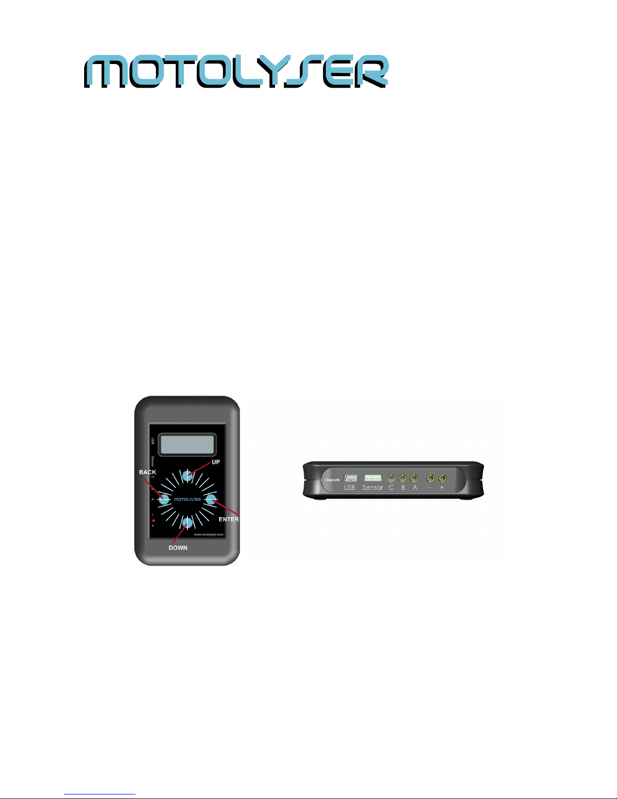
Connection / Navigation
The Motolyser is navigated using the built-in touch panel consisting of four buttons and a
wheel. The buttons are used for navigating the menus while the wheel is unused at the
time of writing. All connections are easily accessed from the side, with the upgrade button
located inside the small hole next to the USB port. The Motolyser is powered by 1 or 2-cell
Li-Po battery connected to the +/- respectively. In case of wrong polarity the LED on the
front panel will light up.
Figure 2: All the connectors to the Motolyser are located
on the side for easy access.
Figure 1: The
Motolyser front panel
with the touch button
functions explained
Quick Start:
– Connect the sensor and phase cables to the motor (A, B and C respectively). The
connection on the Motolyser side is shown in Figure 2.
– Connect the supply battery (1 or 2-cell Li-Po)
– Navigate to Motor Current or Condition Test by using the UP/DOWN touch buttons
– Push right touch button (ENTER), see figure 1
– When the test is completed step amongst the result screens with the UP/DOWN
buttons, or EXIT to go back to main menu
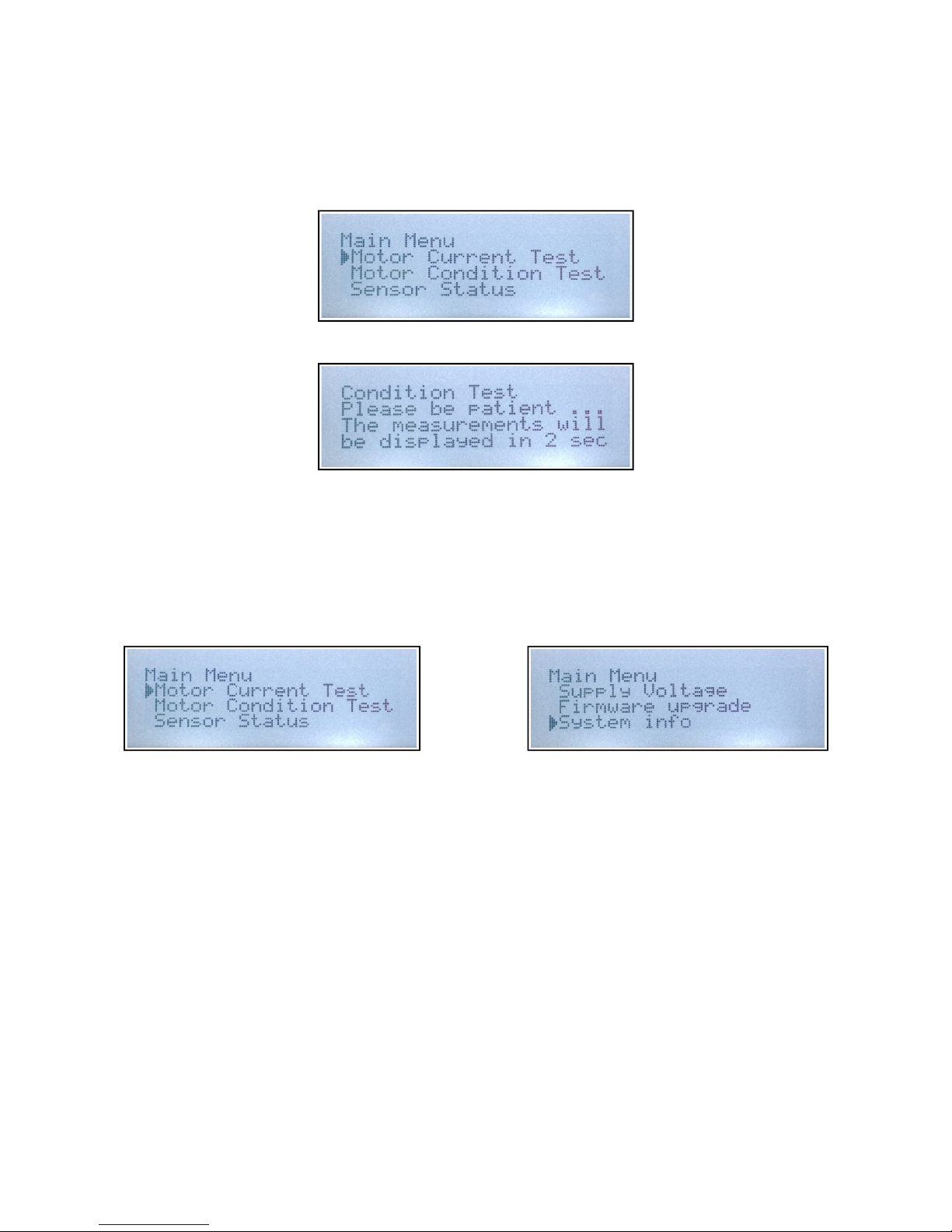
Main Menu
To navigate in the menus and to start the motor the touch buttons are used. There are four
buttons integrated that are used for navigating the menus. Push ENTER to select an item
and EXIT to go back to main menu.
Current Test: Starts a quick test for measuring how the motor operates when
running with end-bell timing.
Condition Test: This is the Traditional Motolyser test for measuring sensor and
magnet condition.
Sensor Status: Shows the status of each sensor element, to verifying sensor
function.
Supply Voltage: Show the voltage of the supply battery.
Firmware Upgrade: Enters the firmware upgrade mode, for connection to the PC
upgrade application using the USB port.
System Info: Displays the hardware version, manufacturing date, and FW
build.
Sensor Status
2014-10-05 [Ver 1.2] www.motolyser.com 2/6
 Loading...