

MOTO GUZZI ambassador V 750 User Manual

Ambassadol'
rider's
handbook
Ambassador
V
750
RIDER
' S
HANDBOOK
2
INTRODUCTION This booklet
is
intended
to
provide owners
with the necessary information on
oper
ating
and
maintaining their machines for maximum
efficiency.
The manual
should be read very carefully
as
most troubles
and
failures arising from
neglect
or
poor
maintenance will be avoided
if
all the instructions herein contained
are
strictly followed.
Don't forget that all
major
overhaul jobs
and
repairs
are
best carried
out
by officially
appointed Moto Guzzi dealers
who
have the
necessary facilities to quickly
and
competen.
tly repair
your
Moto Guzzi.
IN
D E X
Running
in
Controls and accessories
Identification
data
Tool kit
Main features
_ Engine
Frame
Instr
uments
and
controls
Ignition key
Starting
button
Ignition swit
ch
keys
Steering lock
Steering
lock keys
Dimmer switch
and
horn
button
Clutch lever
Twist grip
throttle
control
Air
lever
Gearshift lever
Front
brake
lever
Rear
brake
pedal
Riding instructions
lubrication
chart
lubrication
and
general mainte-
nance
Servicing instructions
lubrication
of
engine
Oil pressure relief valve
Oil
pressure gauge
lubrication
of transmission
lubrication
of
rear
wheel drive
lubrication
of fr
ont
fork and hy-
draulic
dampers
lubrication
of bevels in
the
stee~
ring
....
~~
p,,.
5
•
6
•
JO
•
11
•
12
•
16
•
18
•
19
•
19
•
20
•
20
•
20
•
20
•
20
•
20
•
21
•
21
•
21
•
21
•
22
•
25
•
27
•
29
•
29
•
31
•
31
•
31
•
32
•
33
•
33
3
4
Lubrication of whee! bearings
Lubrication of rear fork bearings
C(!rburation
Air filter
Fuel
tank
Fuel
taps
Mufflers
Valve
gearing
Tappet clearance
Checking
valve riming
Ignition
Distributor
Spark plugs
Checking of ignition timing
Checking
of
ignition advance by
stroboscope lamp
Adjustments
Generator
belt
Clutch
lever
Steering
Steering lock
Front brake lever
Rear brake pedal
Rear
suspension units
Removal of wheels
Front wheel
Rear wheel
Electrical equipment
Wiring diagram -
USA
model
Wiring diagram - European model
p~
ge
33
•
33
• 35
•
40
•
40
•
41
•
42
•
43
•
43
•
43
•
46
•
46
•
47
•
47
•
48
•
51
•
51
•
51
•
51
• 54
• 55
•
57
•
57
•
60
•
60
• 60
• 62
•
71
• 72
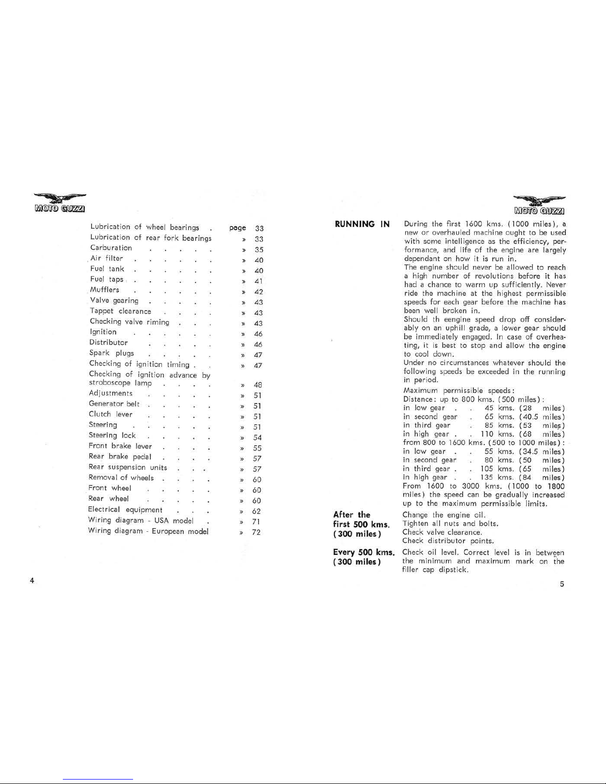
RUNNING
IN
After the
first 500 kms.
(300 miles )
Every 500 kms.
(300 mile
s)
"5iiJ
-
~
During the first 1600 kms.
(1000
miles),
a
new
or
overhauled machine ough t to
be
used
with some
intelligence as the efficiency, per-
formance, and life
of
the engine are largely
dependant on how it
is
run in.
The engine
should never be allowed to reach
a high
number
of revolutions before it has
had a chance to
warm
up sufficiently. Never
ride the machine
at
the highest permissible
speeds for each gear before the machine has
been
well broken in.
Should th eengine speed drop off considerably on an uphill grade, a lower gear should
be immediately engaged.
In
case
of
overhea-
ting,
it
is
best to st
op
and allow the engine
to
cool down.
Under no circumstances whatever
should the
following speeds be exceeded
in
the running
in
period.
Maximum permissible
speeds:
Distance: up to 800 kms.
(500
miles):
in
low gear
45
kms.
(28
miles)
in
second gear
65
kms.
(40.5
miles)
in
third gear
85
kms.
(53
mile})
in
high gear 110 kms.
(68
miles')
from
800 to 1600 kms.
(500
to 1000
miles):
in
low ge(!( 55 kms.
(34.5
miles)
in
second gear 80 kms.
(50
miles)
in
third gear 105 kms.
(65
miles)
in
high gear 135 kms.
(84
miles)
From 1600 to 3000 kms.
(1000
to 1
800
miles) the speed can
be
gradually increased
up to the maximum permissible limits.
Change the engine
oil.
Tighten all nuts and bolts.
Check valve clearance.
Check
distributor
points.
Check
oil level. Correct level
is
in betwEIen
the minimum and maximum mark on the
filler
cap
dipstick.
5
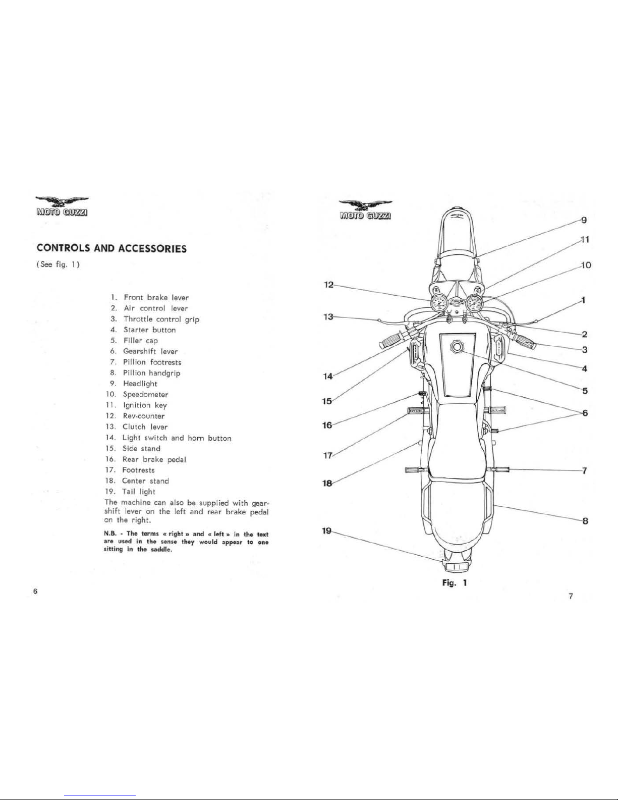
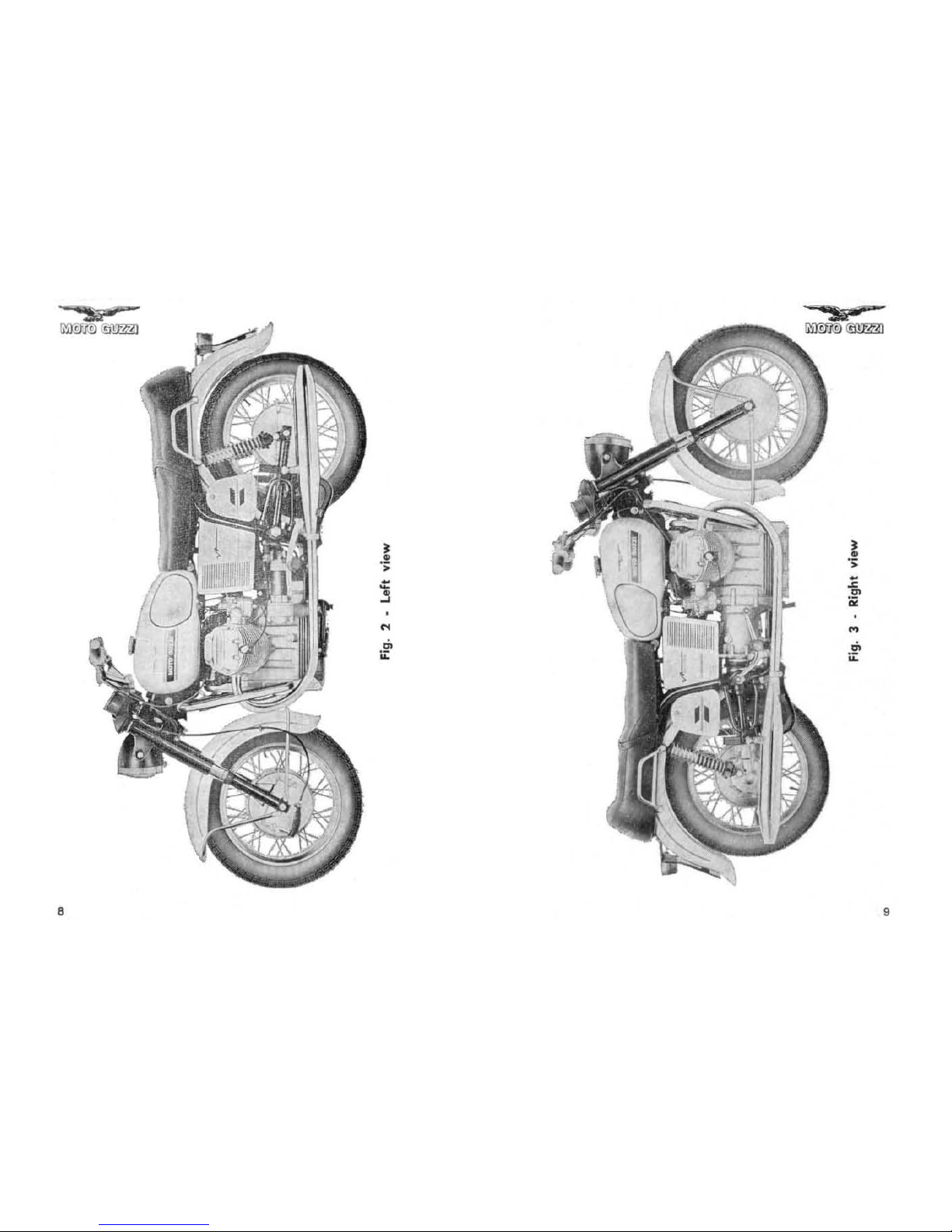
CONTROLS AND ACCESSORIES
(See
fig. I )
•
1. Front
brake
lever
2. Air control lever
3.
Throttle
control
grip
4.
Slarter
button
5. Filler
cap
6. Gearshift lever
7. Pillion footrests
8. Pillion handgrip
9. Headlight
10. Speedometer
11. Ignition key
12. Rev-counter
13.
Clutch lever
14.
light
switch
and
horn
button
15
. Side
stand
16. Rear
brake
pedal
17
. Footrests
18. Center
sland
19. Tail light
The machine can also be supplied with gearshift leve r
on
the
left
and
rear
brake
pedal!
on
the
right.
N.B, •
TIM I ...
ml
... right
" a
nd
• 1ft, ,, In
,he
lui
If.
uo.-d In 1M
.. n ..
t
...
.,
would
app-a. 10
one
IIUi",
In ,
...
udell
•.
1
tt<:"'--"
- 2
~
---
3
::-----
4
14
5
15
16
17
1
Fig
. 1
7
8
9

Identification
data
(See
fig.
4)
10
Every machine
is
identified with a serial num-
ber which
is
stamped on the frame down tube
end
on
the left hend crankcase cover.
Fig
. 4
Tool kit
(See fig.
5)
1.
Box
wrench, 19-21-22 mm.
2.
Open ended wrench, 17-19 mm.
3.
Open ended wrench, 10·11 mm.
4. Tappet adjusting wrench
5.
Box
wrench, 8-9
mm.
6. Allen
key
(5
hex)
7.
Box
wrench, 10·14 mm.
8. Universal pliers
9. Adjustable wrench
10. Screwdriver
11. Ring wrench, 27 mm.
12. Rear
damper
adjusting wrench
13.
Tool
bag
Fig.
5
11
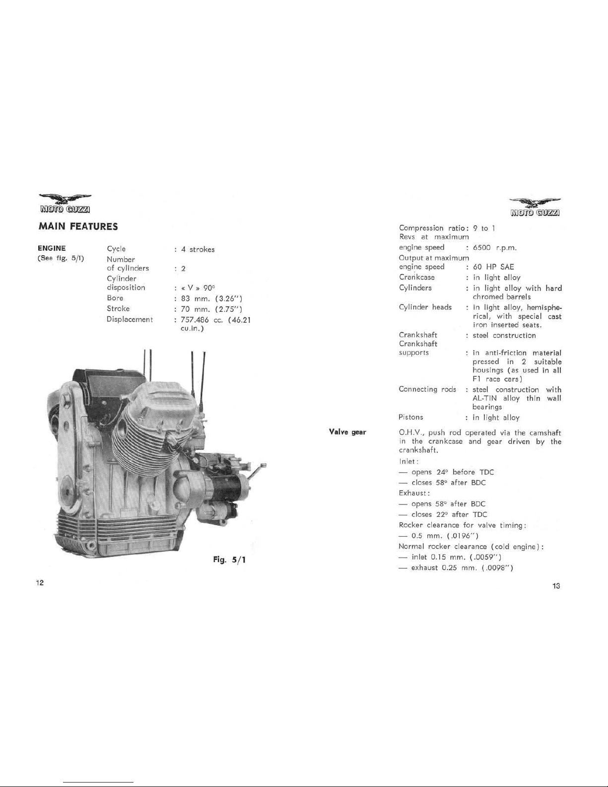
MAIN
FEATURES
ENGINE
(Sea
fig.
5/1)
12
Cycle
Number
of cyli nders
Cylinder
dispo
sition
Bore
Stroke
Displa~emenl
4
strokes
,
«v,. 90"
83
mm
.
(3.26")
70
mm.
(2.75
" )
757.486
ce.
( 46.21
cll.in.)
Fig
. 5/ 1
Valve gear
Compression
ratio:
9 to 1
Re
vs
at
maximum
engine speed 6500 r.p.m.
Output at
mi)Kimum
engine speed
Crankcase
Cylinders
Cylinder
heads
Crankshaft
Crankshaft
supports
Conne<:ting rods
Pistons
60
HP
5AE
in
ligh t
alloy
in light alloy
with
hard
chr
omed barrels
in
light
alloy,
hemisphe-
rical, with special cast
iron
inserted
seats.
steel construction
in
anti·friction
mate
rial
pressed
in 2
suitable
housings
(as
used
in all
Fl
race car
s)
steel construction with
AL·TIN alloy
thin wall
bearings
in
light
alloy
O.H.v., push
rod
operated
via
the
camshaf
t
in
the crankcase
and
gear driven by
the
crankshaft.
Inlet:
- opens 24
<>
before
Toe
- closes
58
<>
after
BOC
E)(haust:
- opens
58" after
BDC
- closes 22'"
after
TDC
Rocker clearance for valve
timing:
-
0.5
mm.
(.0196")
Normal rocker clearance
(co
ld
engine):
inlet
0.15
mm.
(.0059")
- e)(haust
0.25
mm.
(.0098")
Lubrication
Cooling
Ignilion
14
2 DeIl'Orto
carburetors
type
VHB
29
CD
(right)
and
VHB
29
CS
(left)
both gravity
fed
from
the
tank.
Standard carburetor
$etting
Ch
oke
29
mm.
Throttle
slide
60
- Atomizer
265
- Main jet 1
45
- Pilot jet
45
-
Starter
atomizer
80
With needle SV9 set
at
second notch from
top:
idling screw open I
and
112
turns
for
the
left
carburetor
and I and
3
n
.
2
turns
for the right
carburetor.
With needle SV5 third notch from
top:
idling screw open
1
1f~
to 2
turns
for the
left
carburetor
and
2.2112
turns
for the right
carburetor.
Air intake provided with
dry fil
ler
.
Pressure, by gear
pump
driven by
the
crank-
shaft.
Oil
strainer
in
crankcase.
No
rmal lubrication
pressure
3.8·4.2
kgs/sq.
cm.
(54
to
60
Ibs sq.in.) controlled by relief
villive.
Electrically controlled oil
pressure
gauge.
By
air. Cylinder
and
cylinder head deeply
finned.
By
battery
with
automatic
advance distri-
butor.
Initial
advance:
10".
Automatic advillnce: 28".
Ignition
timing 38" full advance.
Starting
Exh
aust system
TRANSMISSION
Clutch
Gear box
Se<o
ndary
drive
Contact
breaker
gap:
0.42-0.48 mm.
(.016"-
.0IS·').
Spark
plug:
n. 225
in
Bosch-Marelli scale o r
equivalent_
Plugs
point
gap:
0.6 mm.
(.023")
Ignitioo coil.
Electric
starter
with
electromagnetic ratchet
control.
Ring
gear
bolted
on
flwheel.
Operated
by
sta
rter
button.
Dual exhaust pipes
and
mufflers.
Twin driven plates, d ry
type, locillted on the
flywheel.
Controlled by lever
on left
hand-
lebar.
Four speeds, frontal engagement.
Conslllnt
mesh gears. Cush drive incorporated.
Separate case bolted
on
crankcllsfI, ope
rated
by
rocker pedal on
the
right side of
the
machine.
Engine gear-box
ratio:
Inlernal gear
ratios:
-
Low
gear
-
Serond
gear
- Third gear .
- High gear
to 1.375
(16-22)
to 2.230
(13·29)
to
1.333
(18·24)
to 0.954
(22·21)
to 0.750
(24-18)
By
constant speed double joint
cardan
shaft
lllyshaft
bevel gears-rear wheel
ratio:
Overall gear
ralios:
-
Low
gear .
-
Serond gear
- Third gear
- High
gear
_
4.375
(8-35)
to 13.4
15
to
8.0
18
10
5.738
to
4.511
15
ijljW1!l
®m
FRAME
Suspension
Wheels
Tires
Tire
pressure
Brakes
Overall
dimensions
and weight
16
Duplex cradle, tubular structure.
Telescopic front fork incorporating hydrauli c
dampers.
Rear swinging fork with externally adjustable
springs.
18)(3
rims, front and rear.
4.00)(18 front and rear, block type (high
speed).
Front
tire:
solo
p<lssenger !
with
1.5 kgs/sq.cm. =
21
p.s.i.
Rear
tire:
solo
with passenger
1.8 kgs/sq.cm. = 25 p.s.i.
2.0 kgs/sq.cm. = 28 p.s.i.
N.S ..
The
~bove
recommendat ion is for
norm
at
riding (
uui
sing
spee
d ).
If
using
the
machi
ne
~
t
co n. lant high
speed
Or
On
motorw
l y" , the
~
bov
e
pr
euure.
should
be incr
eao
ed
by 0 .2 kg
./lq.cm
.
( 2.8 p
.•.
i.
J.
Twin leading shoes front brake operated by
hand lever
on
the right handlebar.
Large rear
brake
opera t
ed
on left hand side
of machine.
Wheelbase
1.470 mts. (about 57.8"
Length
2.245 mts.
{about
88.3"'
Width
0.830 mts.
(about
32.6"
Height
(
dry)
1.070
mts.
(about 42.1"
Minimum ground
clearance 0.150 mts.
(abou t
5.9"
Curb weight
228
kgs.
(about
502 Ibs.)
Performance
Maximum permissible speeds and gradie nts
climbable
in
each gear, solo riding.
Low
gear:
62
kms/h
( 38.5
m.p.h.)
climbing ability:
90%
Second
gear:
104.250
kms/h
(64
.6 m.p.h .
climbing ability:
40%
Third
gear:
145.250
kms/h
(89.2
m.p.h . )
climbing ability:
20%
High
gear:
185.276
kms/h
(liS
m.p.h . )
climbing ability:
8%
Fuel consumption Measured according to
CUNA
standards:
37 m.p.g. (US).
Fuel .
Hld
oil
Fuel
tank:
22.5 liters
(5.84
US
gls.) inclu-
ca
pacities ding about 4 liters reserve
(about 1 US
gl.).
Petrol 98
NO
(Regular
octane) -Sump
3 liters
(31j-l
quarts)
Shell Super Motor Oil 100 -
Transmission
0.750 liters
(1 % pints)
Shell
Spirax 90 E.P. -
Re<lr
wheel drive 0.300 liters
(5/8
pints) Shell Spirax 90
E.P.
- Front fork
dampers
0.160 liters = 5.4 oz
US
Shell Tel-
lux 33.
17
,.....
IID:!li\!)
C!I!m
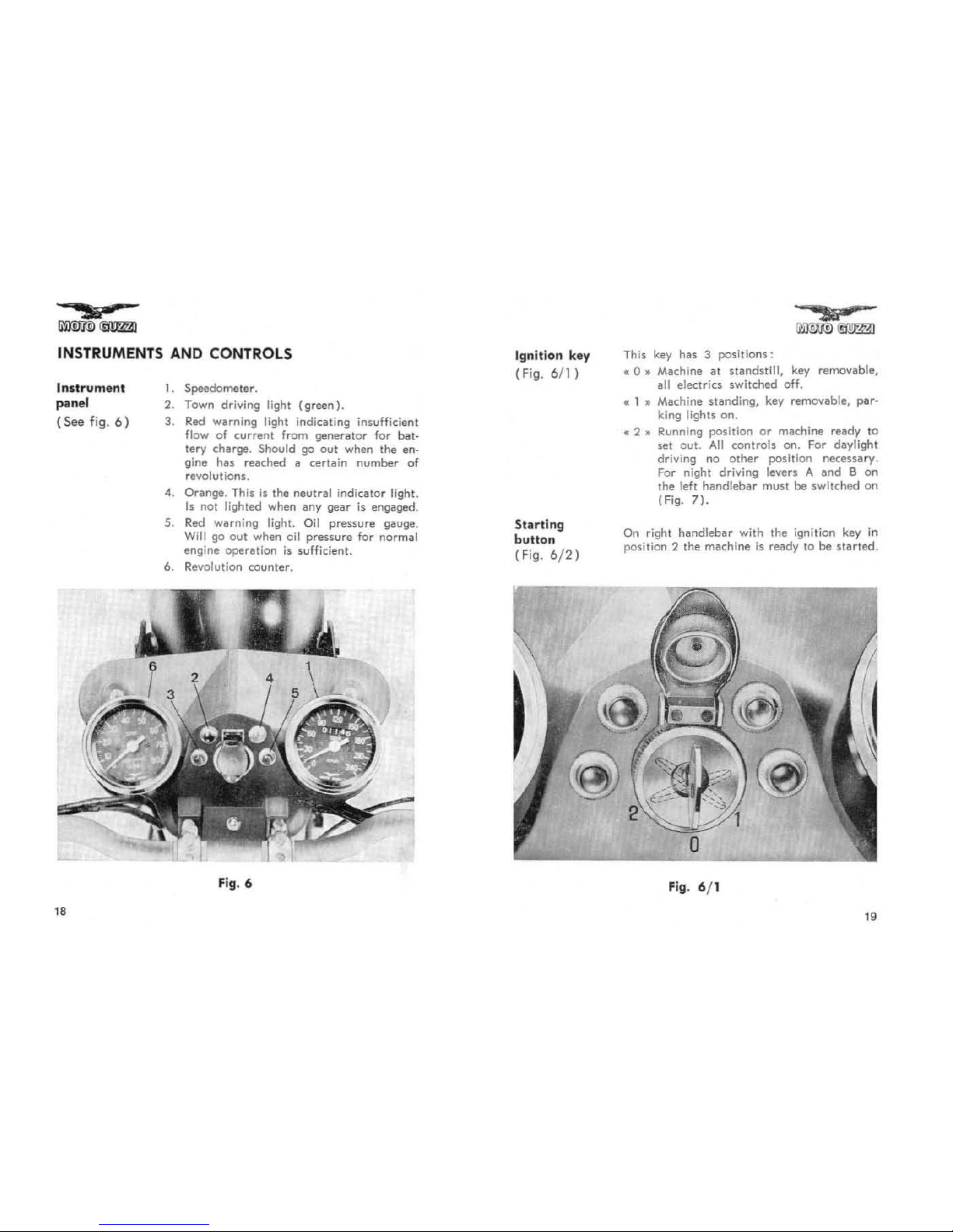
INSTRUMENTS AND CONTROLS
Instrument
panel
(See
fig.
6)
,.
1.
Speedometer.
2.
Town
driving
light
(green),
3.
Red
warning
light
indicating
insufficient
fl
ow
of
current
from
generator
for bal-
tery charge. Should
go
out
when the en-
gine has reached
it
certa
in number
of
revolutions.
4. Orange. This
is
the
neutral
indicato r light.
Is
nOI
lighted when
IIny
gear
is
engaged.
S.
Red
warning
light. Oil
pressure
gauge.
Will go
out
when o
il
pressure
for normal
engine operation
is
sufficient.
6.
Rev
olutio
n counter.
Fig
. 6
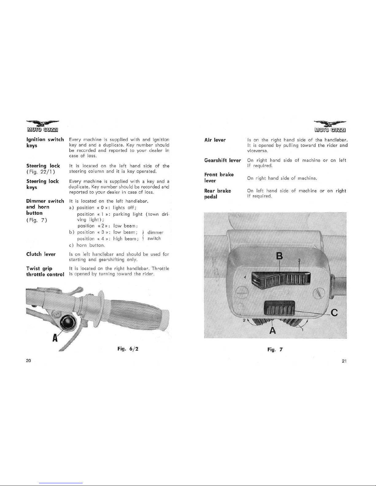
Ignition key
(Fig.
6/1)
Starting
button
(F;9. 6/
2)
This key has 3
positions:
«
0"
Machine at
standstill,
key removable.
i!l1I
electrics switched off.
c I
11
Machine standing, key removable, par-
king
lighls
on.
• 2 " Running
position
or
machine ready
10
set out.
All
controls on. For daylight
driving no
other
position ne<:essary.
For night driving levers A and B
on
the left handlebar must be switched
on
(Fig.
7).
On right handlebar with the ignition key
in
position 2 the machine
is
ready to
be
started.
Fig. 6/ 1
19
Ignition switch
keys
Steering lock
(Fig. 22/
1)
Steering lock
keys
Dimmer
swit
ch
and
horn
button
(Fig.
7)
Clutch lever
Twist
grip
throttle
control
20
Every machine is
supplied
with
and
ignition
key
and and
a duplicate.
Key
number
should
be
recorded and
reported
to your
dealer
in
case
of
loss.
It is located on
the
left
hand
side
of
the
steering
column
and
it
is
key
operated.
Every machine is supplied with a key
and
a
duplicate.
Key
number
should
be
recorded
and
reported
to your dealer in
case
of loss.
It is located on the left
handlebar
.
a)
position
«0,,:
lights
off;
b)
0)
position
.. 1 ,,;
parking
light
(town
dri·
ving
light);
position
«2»
: low
beom;
position
«3"
:
low
beam;
dimmer
position
.. 4
,,;
high
beam;
switch
horn
button.
Is
on
left
handlebar
and
should be used for
starting
and
gearshifting
only.
It
is located
on
the right
handlebar. Throttle
is
opened
by
turning
toward
the rider.
Fig
. 6/ 2
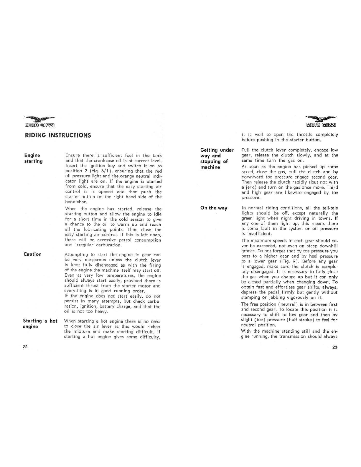
Air lever
Gear
shift
lever
Front
brake
lever
Rear
brake
pedal
Is
on the right
hand
side
of
the
handlebar
.
It is opened
by
pulling
toward
the
rider
and
viceversa.
On
right
hand
side of machine
or
on left
if
required.
On right
hand
side
of machine.
On left
hand side
of machine o r on
right
if required.
Fig
. 7
21
RIDING INSTRUCTIONS
Engine
sta
rting
Caution
Starting a hoi
engine
22
Ensure there is
sufficient
fuel
in
the
tank
and
that
the
crankcase oil
is
at
correct
level.
Insert the ignition key and switch it on
to
position 2
(fig.
6
/1),
ensuring that the red
oil
pressure
light
and
the
orange neutral indi-
cator
lighl
are
on.
If
the engine
is
started
from cold, ensure Ih;!,
the
easy
starting
air
control
is is
opened
and
then push the
starter
button
on the right hand side
of
the
handlebar.
When the engine has
started,
release
the
starting
butlon
and
allow the engine
to
idle
for a
short time
in
the
cold season
to
give
a
chance
to
the
oil
to
warm
up
and reach
all the lubricating points. Then close
the
easy
starting
air control.
If
this
is
left open,
there
will be excessive petrol consumption
and
irregular
carburation.
Attempting to
start
the engine
in
gear can
be
very dangerous unless the clutch lever
is
kept fully dis engaged as with
the
firing
of
the
engine the machine itself may
start
off.
Even
at
very low
temperatures,
the engine
should always
start
easily, provided there
is
sufficient
thrust
from the
starter
motor
and
everything
is
in
good running
order.
If
the engine does not st
art
easily,
do
not
persist
in
many
attempts,
but
check carbu-
ration, ignition,
battery
charge,
and
tha
t the
oil
is
not too heavy.
When
starting
a hot engine there
is
no need
to close the
air
lever as this would richen
the
mixture
and
make
starting
difficult.
If
starting
a hot engine gives some difficulty,
Getting under
way and
stopping
of
machine
On
the way
it
is
well to open the
throttle
completely
before pushing
in
the
starter
bulton.
Pull the clut
ch
lever completely, engage low
gear, release the clutch slowly,
and
at
the
same time
turn
the gas on.
As
soon as the engine has picked up some
speed, close
the
gas, pull the c1ulch
and
by
downward
toe
pressure
engage second gear.
Then release the clutch rapidly
(but
not with
a
jerk)
and
turn
on
the
gas once more. Third
and
high gear
are
likewise engaged by toe
pressure.
In
normal riding conditions, all
the
tell-Iale
lights should be off, e xcept naturally the
green light when night driving
in
towns.
If
anyone
of them light up, this means
there
is
some fault
in
the
system
or
all pressure
is
insufficient.
The
maximu m speeds
in
each
gear
should never be exceeded, not even on steep downhill
grades.
Do
not forget
that
by toa
pressure
you
pass to a higher gear and by heel pressure
to
a lower gear (Fig.
9).
Before any
gear
is
engaged,
make
sure
the clutch
is
comple-
tely disengaged.
It
is
necessary
to
fully close
the gas when
yO\)
change up but it can only
be
closed partially when changing down. To
obtain fast
and
effortless gear shifts, always,
depress
the
pedal firmly
but
gently
without
stamping or jabbing vigorously
on
il.
The free position
(neutral)
is
in
between first
and
second gear.
To
locate this position it is
necessary to shift to low gear
and
then by
slight ( t
oe)
pressure
(half
stroke)
to feel for
neu
tr
al
position.
With the machine standing
still
and
the
en-
gine running,
the
transmission should always
23
 Loading...