

Moto Guzzi 940 Bellagio 1949-2008 Service Manual

MOTO GUZZI DESEA AGRADECERLE
por haber elegido uno de sus productos. Hemos preparado este manual para permitirle apreciar todas sus cualidades. Le aconsejamos que lea todo
su contenido antes de conducir por primera vez. Contiene información, consejos y advertencias para el uso de su vehículo; asimismo, descubrirá
características, detalles y soluciones que lo convencerán de lo acertado de su elección. Estamos seguros de que teniendo todo esto en cuenta, le
resultará fácil conocer su nuevo vehículo, el cual podrá disfrutar por mucho tiempo con total satisfacción. La presente publicación es parte integrante
del vehículo y en caso de venderlo debe ser entregada al nuevo propietario.
MOTO GUZZI WOULD LIKE TO THANK YOU
for choosing one of its products. We have drawn up this booklet to provide a comprehensive overview of your vehicle's quality features. Please read it
carefully before riding the vehicle for the first time. It contains information, tips and precautions for using your vehicle. It also describes features, details
and devices to assure you that you have made the right choice. We believe that if you follow our suggestions, you will soon get to know your new vehicle
well and will use it for a long time at full satisfaction. This booklet is an integral part of the vehicle, and should the vehicle be sold, it must be transferred
to the new owner.
Bellagio
Ed. 05 2008

Las instrucciones de este manual han sido preparadas principalmente para suministrar una guía simple y clara de uso; se indican también las
operaciones de mantenimiento básico y los controles periódicos que se deberán realizar en los CONCESIONARIOS o Talleres autorizados Moto
Guzzi. Además, el manual contiene las instrucciones para que pueda realizar algunas reparaciones simples. Las operaciones que no se describen
explícitamente en esta publicación requieren la disponibilidad de herramientas especiales y/o de conocimientos técnicos específicos. para su ejecución
recomendamos dirigirse a los CONCESIONARIOS o Talleres autorizados Moto Guzzi.
The instructions in this manual have been prepared to offer mainly a simple and clear guide to its use; it also describes routine maintenance procedures
and regular checks that should be carried out on the vehicle at an authorised Moto Guzzi Dealer or Workshop, The booklet also contains instructions
for simple repairs. Any operations not specifically described in this booklet require the use of special tools and/or particular technical knowledge; for
these operations, please take your vehicle to an authorised Moto Guzzi Dealer or Workshop.
2

Seguridad de las personas
Personal safety
El no-cumplimiento total o parcial de estas prescrip-
ciones puede comportar peligro grave para la incolu-
midad de las personas.
Salvaguardia del ambiente
Indica el comportamiento correcto para que el uso del
vehículo no cause ningún daño a la naturaleza.
Integridad del vehículo
El no-cumplimiento total o parcial de estas prescrip-
ciones comporta el peligro de serios daños al vehículo
e incluso la caducidad de la garantía.
Las señales indicadas previamente son de gran importancia. Sirven para evidenciar las partes del manual que requieren de más atención. Como se puede
observar, cada señal está compuesta por un símbolo
gráfico diferente, para facilitar y agilizar la búsqueda
de los temas en las diversas áreas. Antes de poner
en marcha el motor, leer atentamente este manual,
especialmente el apartado "CONDUCCIÓN SEGURA". Su seguridad y la de los demás no depende
solamente de la rapidez de sus reflejos y agilidad, sino también del conocimiento del vehículo, de su eficiencia y del conocimiento de las reglas fundamentales para la CONDUCCIÓN SEGURA. Por lo tanto, le
recomendamos familiarizarse con el vehículo lo suficiente como para circular por la carretera con total
control y seguridad. IMPORTANTE Este manual se
debe considerar como parte integrante del vehículo y
debe acompañarlo en caso de venta.
Failure to completely observe these instructions will
result in serious risk of personal injury.
Safeguarding the environment
Sections marked with this symbol indicate the correct
use of the vehicle to prevent damaging the environ-
ment.
Vehicle intactness
The incomplete or non-observance of these regula-
tions leads to the risk of serious damage to the vehicle
and sometimes even the invalidity of the guarantee.
The sings above are very important. They are used to
highlight those parts of the booklet that should be read
with particular care. As you can see, each sign consists of a different graphic symbol, making it quick and
easy to locate the various topics. Before starting the
engine, read this manual carefully, particularly the
"SAFE RIDING" section. Your safety as well as other's
does not only depend on the quickness of your reflexes and agility, but also on how well you know your
vehicle, its efficiency and your knowledge of the rules
for SAFE RIDING. For your safety, get to know your
vehicle well so as to safely ride and master it in road
traffic IMPORTANT This booklet is an integral part of
the vehicle, and should the vehicle be sold, it must be
transferred to the new owner.
3

4

INDICE
INDEX
NORMAS GENERALES................................................................. 9
Introducción.............................................................................. 10
Monóxido de carbono............................................................... 10
Combustible............................................................................. 11
Componentes calientes............................................................ 12
Puesta en marcha y Conducción............................................. 12
Testigos.................................................................................... 12
Aceite motor y aceite cambio usados...................................... 14
Líquido frenos y embrague...................................................... 15
Electrolito y gas hidrógeno de la batería.................................. 16
Soporte..................................................................................... 17
Comunicación de los defectos que influyen en la seguridad
................................................................................................. 17
VEHÌCULO...................................................................................... 23
Ubicación componentes principales............................................ 25
Tablero de instrumentos.............................................................. 26
Conjunto de instrumentos............................................................ 27
Grupo testigos............................................................................. 27
Representacion visual digital por cristales liquidos..................... 28
Teclas de mando...................................................................... 28
Funciones avanzadas.............................................................. 31
Conmutador de encendido....................................................... 37
Bloqueo del volante.................................................................. 38
Luces de aparcamiento............................................................ 38
Pulsante claxon........................................................................... 39
Conmutador intermitentes........................................................... 40
Commutador luces....................................................................... 40
Pulsador ráfaga luz de carretera................................................. 41
Pulsante arranque....................................................................... 41
Interruptor parada motor.............................................................. 41
Mando del starter manual............................................................ 42
GENERAL RULES............................................................................ 9
Foreword.................................................................................... 10
Carbon monoxide....................................................................... 10
Fuel............................................................................................ 11
Hot components......................................................................... 12
Start off and Riding..................................................................... 12
Warning lights............................................................................. 12
Used engine oil and gearbox oil................................................. 14
Brake and clutch fluid................................................................. 15
Battery hydrogen gas and electrolyte......................................... 16
Stand.......................................................................................... 17
Reporting of defects that affect safety........................................ 17
VEHICLE........................................................................................... 23
Arrangement of the main components........................................... 25
Dashboard..................................................................................... 26
Instrument panel............................................................................ 27
Light unit........................................................................................ 27
Digital lcd display........................................................................... 28
Control buttons........................................................................... 28
Advanced functions.................................................................... 31
Ignition switch............................................................................. 37
Locking the steering wheel......................................................... 38
Parking lights.............................................................................. 38
Horn button.................................................................................... 39
Switch direction indicators............................................................. 40
High/low beam selector.................................................................. 40
Passing button............................................................................... 41
Start-up button............................................................................... 41
Engine stop switch......................................................................... 41
Manual starter control.................................................................... 42
Opening the saddle.................................................................... 42
5

Abertura sillín........................................................................... 42
Compartimiento porta-doc./kit herramientas............................ 43
La identificación........................................................................... 43
EL USO........................................................................................... 45
Controles..................................................................................... 46
Abastecimiento............................................................................ 49
Regulación amortiguadores traseros........................................... 51
Regulación horquilla delantera.................................................... 53
Regulación leva freno delantero.................................................. 54
Regulación leva embrague.......................................................... 55
Rodaje......................................................................................... 55
Puesta en marcha del motor........................................................ 57
Aparcamiento............................................................................... 58
Escape catalítico.......................................................................... 59
Soporte........................................................................................ 60
Sugerencias contra los robos...................................................... 61
Normas basicás de seguridad..................................................... 63
EL MANTENIMIENTO.................................................................... 69
Premisa........................................................................................ 70
Control del nivel de aceite motor.............................................. 71
Llenado de aceite motor........................................................... 72
Sustitución aceite motor........................................................... 73
Nivel aceite cardán...................................................................... 75
Nivel aceite cambio...................................................................... 76
Neumáticos.................................................................................. 76
Desmontaje bujía......................................................................... 77
Control nivel aceite frenos........................................................... 80
Llenado liquido circuito de frenos............................................. 81
Control líquido embrague............................................................ 84
Reposición líquido embrague................................................... 84
Puesta en servicio de una batería nueva................................. 87
Comprobacion del nivel del electrolito..................................... 88
Recarga batería....................................................................... 88
Larga inactividad.......................................................................... 89
Fusibles....................................................................................... 90
Bombillas..................................................................................... 93
Regulación proyector............................................................... 96
Indicadores de dirección delanteros............................................ 97
Grupo óptico trasero.................................................................... 98
Glove/tool kit compartment......................................................... 43
Identification................................................................................... 43
USE................................................................................................... 45
Checks........................................................................................... 46
Refuelling....................................................................................... 49
Rear shock absorbers adjustment................................................. 51
Front fork adjustment..................................................................... 53
Justering af greb til forbremse....................................................... 54
Clutch lever adjustment................................................................. 55
Running in...................................................................................... 55
Starting up the engine.................................................................... 57
Parking........................................................................................... 58
Catalytic silencer............................................................................ 59
Stand.............................................................................................. 60
Suggestion to prevent theft............................................................ 61
Basic safety rules........................................................................... 63
MAINTENANCE................................................................................ 69
Foreword........................................................................................ 70
Engine oil level check................................................................. 71
Engine oil top-up........................................................................ 72
Engine oil change....................................................................... 73
Universal joint oil level................................................................... 75
Gearbox oil level............................................................................ 76
Tyres.............................................................................................. 76
Spark plug dismantlement............................................................. 77
Checking the brake oil level........................................................... 80
Braking system fluid top up........................................................ 81
Checking clutch fluid...................................................................... 84
Topping up clutch fluid............................................................... 84
Use of a new battery.................................................................. 87
Checking the electrolyte level..................................................... 88
Charging the battery................................................................... 88
Long periods of inactivity............................................................... 89
Fuses............................................................................................. 90
Lamps............................................................................................ 93
Headlight adjustment.................................................................. 96
Front direction indicators................................................................ 97
Rear optical unit............................................................................. 98
Rear turn indicators........................................................................ 98
6

Indicadores de dirección traseros................................................ 98
Luz placa..................................................................................... 99
Espejos retrovisores.................................................................... 100
Freno de disco delantero y trasero.............................................. 101
Inactividad del vehiculo................................................................ 103
Limpieza del vehiculo.................................................................. 104
Transporte................................................................................... 108
DATOS TÉCNICOS........................................................................ 109
Herramientas en dotación............................................................ 117
EL MANTENIMIENTO PROGRAMADO......................................... 119
Tabla manutención programada.................................................. 120
PREPARACIONES ESPECIALES................................................. 129
Índice accesorios......................................................................... 130
Number plate light.......................................................................... 99
Rear-view mirrors........................................................................... 100
Front and rear disc brake............................................................... 101
Periods of inactivity........................................................................ 103
Cleaning the vehicle....................................................................... 104
Transport........................................................................................ 108
TECHNICAL DATA........................................................................... 109
Kit equipment................................................................................. 117
PROGRAMMED MAINTENANCE.................................................... 119
Scheduled maintenance table........................................................ 120
SPECIAL FITTINGS.......................................................................... 129
Accessories index.......................................................................... 130
7

8

Bellagio
Cap. 01
Normas generales
Chap. 01
General rules
9

Introducción
Foreword
NOTA
EL TIEMPO PREVISTO PARA REALI-
ZAR LAS OPERACIONES DE MANTENIMIENTO, DEBE SER REDUCIDO A
LA MITAD SI EL VEHÍCULO SE UTILIZA EN ZONAS LLUVIOSAS, POLVORIENTAS, EN RECORRIDOS ACCIDENTADOS O EN CONDUCCIÓN
DEPORTIVA.
Monóxido de carbono
Si es necesario hacer funcionar el motor
para poder efectuar alguna operación,
asegurarse de que esto ocurra en un espacio abierto o en un ambiente ventilado
de manera adecuada. Nunca hacer funcionar el motor en espacios cerrados. Si
se trabaja en un espacio cerrado, utilizar
un sistema de evacuación de los humos
de escape.
ATENCIÓN
LOS HUMOS DE ESCAPE CONTIENEN
MONÓXIDO DE CARBONO, UN GAS
VENENOSO QUE PUEDE PROVOCAR
LA PÉRDIDA DE CONOCIMIENTO E
INCLUSO LA MUERTE.
NOTE
CARRY OUT MAINTENANCE OPERA-
TIONS AT HALF THE INTERVALS
SHOWN IF THE VEHICLE IS USED IN
WET OR DUSTY AREAS, OFF ROAD
OR FOR SPORTING APPLICATIONS.
Carbon monoxide
If you need to keep the engine running in
order to perform a procedure, please ensure that you do so in an open or very well
ventilated area. Never let the engine run
in an enclosed area. If you do work in an
enclosed area, make sure to use a
smoke-extraction system.
CAUTION
EXHAUST EMISSIONS CONTAIN
CARBON MONOXIDE, A POISONOUS
GAS WHICH CAN CAUSE LOSS OF
CONSCIOUSNESS AND EVEN
DEATH.
10
Combustible
1 Normas generales / 1 General rules
Fuel
ATENCIÓN
EL COMBUSTIBLE UTILIZADO PARA
LA PROPULSIÓN DE LOS MOTORES
DE EXPLOSIÓN ES EXTREMADAMENTE INFLAMABLE Y PUEDE RESULTAR EXPLOSIVO EN DETERMINADAS CONDICIONES. CONVIENE
REALIZAR EL REABASTECIMIENTO
Y LAS OPERACIONES DE MANTENIMIENTO EN UNA ZONA VENTILADA Y
CON EL MOTOR APAGADO. NO FUMAR DURANTE EL REABASTECIMIENTO NI CERCA DE LOS VAPORES
DE COMBUSTIBLE, Y EVITAR ABSOLUTAMENTE EL CONTACTO CON
LLAMAS DESNUDAS, CHISPAS Y
CUALQUIER OTRA FUENTE QUE PODRÍA HACER QUE EL COMBUSTIBLE
SE ENCIENDA O EXPLOTE.
NO ARROJAR EL COMBUSTIBLE AL
MEDIO AMBIENTE.
MANTENER FUERA DEL ALCANCE
DE LOS NIÑOS.
CAUTION
FUEL USED TO POWER INTERNAL
COMBUSTION ENGINES IS HIGHLY
FLAMMABLE AND CAN BECOME EXPLOSIVE UNDER SPECIFIC CONDITIONS. IT IS THEREFORE RECOMMENDED TO CARRY OUT REFUELLING AND MAINTENANCE PROCEDURES IN A VENTILATED AREA WITH
THE ENGINE OFF. DO NOT SMOKE
DURING REFUELLING AND NEAR
FUEL VAPOURS, AVOID ANY CONTACT WITH NAKED FLAMES,
SPARKS OR OTHER SOURCES
WHICH MAY CAUSE THEM TO IGNITE
OR EXPLODE.
DO NOT DISPOSE OF FUEL IN THE
ENVIRONMENT.
KEEP OUT OF THE REACH OF CHILDREN
LA CAÍDA O LA EXCESIVA INCLINACIÓN DEL VEHÍCULO PUEDEN PRO-
11
VEHICLE FALL OR EXCESSIVE INCLINATION CAN CAUSE FUEL TO SPILL
OUT.

DUCIR DERRAMES DE COMBUSTIBLE.
Componentes calientes
El motor y los componentes de la instalación de escape alcanzan altas temperaturas y permanecen calientes durante
un cierto período, incluso después de
apagar el motor. Para manipular estos
componentes, utilizar guantes aislantes
o esperar hasta que el motor y la instalación de escape se hayan enfriado.
Puesta en marcha y
Conducción
ATENCIÓN
SI DURANTE LA CONDUCCIÓN, EN EL
TABLERO SE ENCIENDE EL TESTIGO
DE RESERVA DE COMBUSTIBLE,
SIGNIFICA QUE COMIENZA A UTILIZARSE LA RESERVA.
REPONER COMBUSTIBLE LO ANTES
POSIBLE.
Testigos
SI EL TESTIGO LED ALARMA Y EL
ICONO DE DIAGNÓSTICO " SERVICE"
SE ENCIENDEN DURANTE EL FUNCIONAMIENTO NORMAL DEL MOTOR, SIGNIFICA QUE LA CENTRALI-
Hot components
The engine and the exhaust system components get very hot and remain in this
condition for a certain time interval after
the engine has been switched off. Before
handling these components, make sure
that you are wearing insulating gloves or
wait until the engine and the exhaust system have cooled down.
Start off and Riding
CAUTION
IF THE LOW FUEL WARNING LIGHT
ON THE INSTRUMENT PANEL TURNS
ON WHILE RIDING, THIS MEANS THE
RESERVE IS BEING USED.
REFUEL AS SOON AS POSSIBLE.
Warning lights
IF THE ALARM LED WARNING LIGHT
AND THE " SERVICE" DIAGNOSIS
ICON TURN ON DURING REGULAR
ENGINE OPERATION, IT MEANS
THAT THE ELECTRONIC CONTROL
12
1 Normas generales / 1 General rules
TA ELECTRÓNICA HA DETECTADO
ALGUNA ANOMALÍA.
EN MUCHOS CASOS EL MOTOR CONTINÚA FUNCIONANDO CON RENDIMIENTO LIMITADO; DIRIGIRSE INMEDIATAMENTE A UN CONCESIONARIO
OFICIAL Moto Guzzi.
DESPUÉS DE LOS PRIMEROS 1.000
KM (625 MILLAS) Y SUCESIVAMENTE
CADA 10.000 KM (6.250 MILLAS), EN
LA PANTALLA DERECHA SE VISUALIZA EL ICONO "SERVICE".
EN ESTE CASO, DIRIGIRSE A UN
CONCESIONARIO OFICIAL Moto Guzzi, PARA REALIZAR LAS INTERVENCIONES PREVISTAS EN LA FICHA DE
MANTENIMIENTO PERIÓDICO.
UNIT HAS DETECTED SOME FAILURE.
IN MANY CASES THE ENGINE CONTINUES TO WORK WITH LIMITED
PERFORMANCE; IMMEDIATELY
CONTACT AN OFFICIAL Moto Guzzi
DEALER.
AFTER THE FIRST 1000 KM (625
MILES) AND THEN EVERY 10000 KM
(6250 MILES), THE "SERVICE" ICON
APPEARS ON THE RIGHT DISPLAY.
IF THIS OCCURS TAKE YOUR vehicle
TO AN OFFICIAL Moto Guzzi DEALER
TO CARRY OUT THE MAINTENANCE
OPERATIONS SPECIFIED IN THE PERIODIC MAINTENANCE CHART.
SI EL TESTIGO DE ALARMA Y EL ICONO EN LA PANTALLA PRESIÓN ACEITE MOTOR PERMANECEN ENCENDIDOS, O SE ENCIENDEN DURANTE EL
FUNCIONAMIENTO NORMAL DEL
MOTOR, SIGNIFICA QUE LA PRESIÓN
DEL ACEITE EN EL CIRCUITO ES INSUFICIENTE.
EN ESTE CASO CONTROLAR EL NIVEL DE ACEITE DEL MOTOR Y SI NO
FUERA EL CORRECTO, DETENERLO
13
IF THE ALARM WARNING LIGHT AND
THE ICON ON THE ENGINE OIL PRESSURE DISPLAY REMAIN ON, OR IF
THEY TURN ON DURING ENGINE
REGULAR OPERATION, IT MEANS
THAT THE OIL PRESSURE IN THE
CIRCUIT IS TOO LOW.
IN THIS CASE, CHECK THE ENGINE
OIL LEVEL AND IF IT IS NOT CORRECT, STOP THE ENGINE IMMEDIATELY AND TOP-UP WITH OIL.
INMEDIATAMENTE Y RESTABLECER
EL NIVEL.
DIRIGIRSE A UN CONCESIONARIO
OFICIAL Moto Guzzi PARA QUE CONTROLE LA INSTALACIÓN.
CONTACT AN OFFICIAL Moto Guzzi
Dealer TO CHECK THE CIRCUIT.
Aceite motor y aceite cambio
usados
ATENCIÓN
EN CASO DE INTERVENCIONES DE
MANTENIMIENTO, SE RECOMIENDA
EL USO DE GUANTES DE LÁTEX.
EL ACEITE MOTOR O DEL CAMBIO
DE VELOCIDADES PUEDE PROVOCAR SERIOS DAÑOS EN LA PIEL SI
SE MANIPULA POR MUCHO TIEMPO
Y COTIDIANAMENTE.
SE RECOMIENDA LAVAR CUIDADOSAMENTE LAS MANOS DESPUÉS DE
HABERLO EMPLEADO.
ENTREGARLO O HACERLO RETIRAR
POR LA EMPRESA DE RECUPERACIÓN DE ACEITES USADOS MÁS
CERCANA O POR EL PROVEEDOR.
NO ARROJAR EL ACEITE AL MEDIO
AMBIENTE
MANTENER FUERA DEL ALCANCE
DE LOS NIÑOS.
Used engine oil and gearbox
oil
CAUTION
IT IS ADVISABLE TO WEAR LATEX
GLOVES WHEN SERVICING THE VEHICLE.
THE ENGINE OR GEARBOX OIL MAY
CAUSE SERIOUS INJURIES TO THE
SKIN IF HANDLED FOR PROLONGED
PERIODS OF TIME AND ON A REGULAR BASIS.
WASH YOUR HANDS CAREFULLY
AFTER HANDLING OIL.
HAND THE OIL OVER TO OR HAVE IT
COLLECTED BY THE NEAREST USED
OIL RECYCLING COMPANY OR THE
SUPPLIER.
DO NOT DISPOSE OF OIL IN THE ENVIRONMENT
KEEP OUT OF THE REACH OF CHILDREN
14

Líquido frenos y embrague
1 Normas generales / 1 General rules
Brake and clutch fluid
Líquido frenos y embrague
LOS LÍQUIDOS DE FRENOS Y DEL
EMBRAGUE PUEDEN DAÑAR LAS
SUPERFICIES PINTADAS, DE PLÁSTICO O DE GOMA. CUANDO SE REALIZA EL MANTENIMIENTO DEL SISTEMA DE FRENOS O DEL EMBRAGUE, PROTEGER ESTOS COMPONENTES CON UN PAÑO LIMPIO.
UTILIZAR SIEMPRE ANTIPARRAS DE
PROTECCIÓN PARA REALIZAR EL
MANTENIMIENTO DE ESTOS SISTEMAS. EL LÍQUIDO DE FRENOS Y DEL
EMBRAGUE SON SUMAMENTE DAÑINOS PARA LOS OJOS. EN CASO DE
CONTACTO ACCIDENTAL CON LOS
OJOS, ENJUAGAR INMEDIATAMENTE CON ABUNDANTE AGUA FRÍA Y
LIMPIA, Y CONSULTAR INMEDIATAMENTE A UN MÉDICO.
MANTENER FUERA DEL ALCANCE
DE LOS NIÑOS.
Brake and clutch fluid
BRAKE AND CLUTCH FLUIDS CAN
DAMAGE THE PLASTIC OR RUBBER
PAINTED SURFACES. WHEN SERVICING THE BRAKING SYSTEM OR THE
CLUTCH SYSTEM PROTECT THESE
COMPONENTS WITH A CLEAN
CLOTH. ALWAYS WEAR PROTECTIVE GOGGLES WHEN SERVICING
THESE SYSTEMS. BRAKE AND
CLUTCH FLUIDS ARE EXTREMELY
HARMFUL FOR YOUR EYES. IN THE
EVENT OF ACCIDENTAL CONTACT
WITH YOUR EYES, RINSE THEM IMMEDIATELY WITH ABUNDANT COLD,
CLEAN WATER AND SEEK MEDICAL
ADVICE.
KEEP OUT OF THE REACH OF CHILDREN
15

Electrolito y gas hidrógeno de
la batería
Battery hydrogen gas and
electrolyte
ATENCIÓN
EL ELECTROLITO DE LA BATERÍA ES
TÓXICO, CÁUSTICO Y EN CONTACTO
CON LA EPIDERMIS PUEDE CAUSAR
QUEMADURAS, YA QUE CONTIENE
ÁCIDO SULFÚRICO. USAR GUANTES
BIEN ADHERENTES E INDUMENTARIA DE PROTECCIÓN AL MANIPULAR
EL ELECTROLITO DE LA BATERÍA. SI
EL LÍQUIDO DEL ELECTROLITO ENTRA EN CONTACTO CON LA PIEL,
LAVAR CON ABUNDANTE AGUA
FRESCA. ES MUY IMPORTANTE PROTEGER LOS OJOS, YA QUE INCLUSO
UNA CANTIDAD MINÚSCULA DE ÁCIDO DE LA BATERÍA PUEDE CAUSAR
CEGUERA. SI EL LÍQUIDO ENTRA EN
CONTACTO CON LOS OJOS, LAVAR
CON ABUNDANTE AGUA DURANTE
QUINCE MINUTOS, LUEGO DIRIGIRSE INMEDIATAMENTE A UN OCULISTA. SI SE INGIERE LÍQUIDO ACCIDENTALMENTE, BEBER ABUNDANTE CANTIDAD DE AGUA O LECHE,
CONTINUAR CON LECHE DE MAGNESIA O ACEITE VEGETAL, LUEGO DIRIGIRSE INMEDIATAMENTE A UN MÉDICO. LA BATERÍA EMANA GASES
EXPLOSIVOS: CONVIENE MANTENERLA ALEJADA DE LLAMAS, CHISPAS, CIGARRILLOS Y CUALQUIER
OTRA FUENTE DE CALOR. PREVER
CAUTION
BATTERY ELECTROLYTE IS TOXIC,
CORROSIVE AND AS IT CONTAINS
SULPHURIC ACID, IT CAN CAUSE
BURNS WHEN IN CONTACT WITH
THE SKIN. WHEN HANDLING BATTERY ELECTROLYTE, WEAR TIGHTFITTING GLOVES AND PROTECTIVE
APPAREL. IN THE EVENT OF SKIN
CONTACT WITH THE ELECTROLYTIC
FLUID, RINSE WELL WITH PLENTY OF
CLEAN WATER. IT IS PARTICULARLY
IMPORTANT TO PROTECT YOUR
EYES BECAUSE EVEN TINY
AMOUNTS OF BATTERY ACID MAY
CAUSE BLINDNESS. IF THE FLUID
GETS INTO CONTACT WITH YOUR
EYES, WASH WITH ABUNDANT WATER FOR FIFTEEN MINUTES AND
CONSULT AN EYE SPECIALIST IMMEDIATELY. IF THE FLUID IS ACCIDENTALLY SWALLOWED, DRINK LARGE
QUANTITIES OF WATER OR MILK,
FOLLOWED BY MILK OF MAGNESIA
OR VEGETABLE OIL AND SEEK MEDICAL ADVICE IMMEDIATELY. THE
BATTERY RELEASES EXPLOSIVE
GASES; KEEP IT AWAY FROM
FLAMES, SPARKS, CIGARETTES OR
ANY OTHER HEAT SOURCES. ENSURE ADEQUATE VENTILATION
16

1 Normas generales / 1 General rules
UNA AIREACIÓN ADECUADA AL
REALIZAR EL MANTENIMIENTO O LA
RECARGA DE LA BATERÍA.
MANTENER FUERA DEL ALCANCE
DE LOS NIÑOS.
EL LÍQUIDO DE LA BATERÍA ES CORROSIVO. NO DERRAMARLO NI DESPARRAMARLO, ESPECIALMENTE
SOBRE LAS PARTES DE PLÁSTICO.
ASEGURARSE DE QUE EL ÁCIDO
ELECTROLÍTICO SEA EL ESPECÍFICO PARA LA BATERÍA QUE SE DESEA ACTIVAR.
WHEN SERVICING OR RECHARGING
THE BATTERY.
KEEP OUT OF THE REACH OF CHILDREN
BATTERY LIQUID IS CORROSIVE. DO
NOT POUR OR SPILL IT, PARTICULARLY ON PLASTIC COMPONENTS.
ENSURE THAT THE ELECTROLYTIC
ACID IS COMPATIBLE WITH THE BATTERY TO BE ACTIVATED.
Soporte
ANTES DE SALIR, ASEGURARSE
QUE EL CABALLETE HAYA REGRESADO COMPLETAMENTE A SU POSICIÓN.
NO CARGAR SOBRE EL CABALLETE
LATERAL EL PESO DEL CONDUCTOR NI EL DEL PASAJERO.
Comunicación de los defectos
que influyen en la seguridad
PRECAUCIONES E INFORMACIÓN
GENERAL
Al realizar la reparación, el desmontaje y
el montaje del vehículo, se deben respe-
17
Stand
BEFORE SETTING OFF, MAKE SURE
THE STAND HAS BEEN COMPLETELY
RETRACTED TO ITS POSITION.
DO NOT REST THE RIDER'S OR PASSENGER'S WEIGHT ON THE SIDE
STAND.
Reporting of defects that
affect safety
GENERAL PRECAUTIONS AND INFORMATION

tar con exactitud las siguientes recomendaciones.
When repairing, dismantling and reassembling the vehicle follow the recommendations reported below carefully.
ANTES DE DESMONTAR LOS COMPONENTES
•
Eliminar suciedad, barro, polvo
y cuerpos extraños del vehículo
antes de desmontar los componentes. Utilizar, en los casos
previstos, las herramientas especiales diseñadas para este
vehículo.
DESMONTAJE DE LOS COMPONENTES
•
No aflojar y/o apretar los tornillos y las tuercas utilizando pinzas u otras herramientas, utilizar siempre la llave adecuada.
•
Marcar las posiciones en todas
las uniones de conexiones (tubos, cables, etc.) antes de separarlas, e identificarlas con diferentes marcas distintivas.
•
Cada pieza se debe marcar con
claridad para que pueda ser
identificada en la fase de instalación.
•
Limpiar y lavar cuidadosamente
los componentes desmontados,
con detergente de bajo grado de
inflamabilidad.
•
Mantener juntas las piezas acopladas entre sí, ya que se han
"adaptado" una a otra como
BEFORE REMOVING COMPONENTS
•
Before dismantling components, remove dirt, mud, dust
and foreign bodies from the vehicle. Use the special tools designed for this bike, as required.
COMPONENTS REMOVAL
•
Do not loosen and/or tighten
screws and nuts using pliers or
other tools than the especially
designed wrench.
•
Mark positions on all connection
joints (pipes, cables etc.) before
separating them, and identify
them with distinctive symbols.
•
Each component needs to be
clearly marked in order to be
identified during reassembly.
•
Clean and wash the dismantled
components carefully using a
low-flammability detergent.
•
Keep coupled parts together
since they have "adjusted" to
each other due to normal wear
and tear.
•
Some components must be
used together or replaced altogether.
•
Keep away from heat sources.
18

1 Normas generales / 1 General rules
consecuencia del desgaste normal.
•
Algunos componentes se deben
utilizar juntos o sustituirlos por
completo.
•
Mantenerlos alejados de las
fuentes de calor.
MONTAJE DE LOS COMPONENTES
ATENCIÓN
LOS COJINETES DEBEN GIRAR LI-
BREMENTE, SIN ATASCAMIENTOS NI
RUIDOS, DE LO CONTRARIO SE DEBEN SUSTITUIR.
•
Utilizar exclusivamente PIEZAS
DE REPUESTO ORIGINALES
Moto Guzzi.
•
Usar sólo los lubricantes y el
material de consumo recomendados.
•
Lubricar las piezas (en los casos en que sea posible) antes
de montarlas.
•
Al apretar los tornillos y las tuercas, comenzar con los de diámetro mayor o con los internos
y proceder en diagonal. Apretar
en varios pasos antes de aplicar
el par de apriete indicado.
•
Si las tuercas autoblocantes, las
juntas, los anillos de estanqueidad, los anillos elásticos, las
juntas tóricas, los pasadores y
los tornillos presentan daños en
REASSEMBLY OF COMPONENTS
CAUTION
BEARINGS MUST BE ABLE TO RO-
TATE FREELY, WITHOUT JAMMING
AND/OR NOISE: OTHERWISE, THEY
NEED TO BE REPLACED.
•
Only use ORIGINAL Moto Guzzi
SPARE PARTS.
•
Comply with lubricant and consumables usage guidelines.
•
Lubricate parts (whenever possible) before reassembling
them.
•
When tightening nuts and
screws, start from the ones with
the largest section or from the
internal ones, moving diagonally. Tighten nuts and screws in
successive steps before applying the tightening torque.
•
Always replace self-locking
nuts, washers, sealing rings, circlips, O-rings, split pins and
screws with new ones if their
tread is damaged.
•
When fitting bearings, make
sure to lubricate them well.
19

la rosca, sustituir siempre por
otros nuevos.
•
Cuando se montan los cojinetes, lubricarlos abundantemente.
•
Controlar que todos los componentes se hayan montado correctamente.
•
Después de una intervención de
reparación o de mantenimiento
periódico, realizar los controles
preliminares y probar el vehículo en una propiedad privada o
en una zona de baja intensidad
de circulación.
•
Limpiar todas las superficies de
acoplamiento, los bordes de los
retenes de aceite y las juntas
antes de montarlos. Aplicar una
ligera película de grasa a base
de litio en los bordes de los retenes de aceite. Montar los retenes de aceite y los cojinetes
con la marca o número de fabricación orientados hacia afuera
(lado visible).
•
Check that each component is
fitted correctly.
•
After a repair or routine maintenance procedure, carry out preride checks and test the vehicle
on private grounds or in an area
with low traffic density.
•
Clean all junction surfaces, oil
guard rims and washers before
refitting them. Smear a light layer of lithium-based grease on
the oil guard rims. Reassemble
the oil guard and the bearings
with the brand or lot number facing outward (visible side).
CONECTORES ELÉCTRICOS
Los conectores eléctricos se deben desconectar del siguiente modo; el incumplimiento de estos procedimientos provoca
daños irreparables en el conector y en el
mazo de cables:
Si existen, presionar los respectivos ganchos de seguridad.
20
ELECTRIC CONNECTORS
Electric connectors must be disconnected as described below; failure to comply
with this procedure causes irreparable
damage to both the connector and the
cable harness:
Press the relevant safety hooks, if any.

1 Normas generales / 1 General rules
•
Aferrar los dos conectores y extraerlos tirando en sentido
opuesto uno del otro.
•
Si hay suciedad, herrumbre, humedad, etc., limpiar cuidadosamente el interior del conector
utilizando un chorro de aire
comprimido.
•
Asegurarse de que los cables
estén correctamente fijados a
los terminales interiores de los
conectores.
•
Luego introducir los dos conectores, cerciorándose de que
queden bien acoplados (si poseen los ganchos opuestos, se
oirá el típico "clic").
ATENCIÓN
NO TIRAR DE LOS CABLES PARA DE-
SENGANCHAR LOS DOS CONECTORES.
NOTA
LOS DOS CONECTORES POSEEN UN
SOLO SENTIDO DE INSERCIÓN: PRESENTARLOS PARA EL ACOPLAMIENTO EN EL SENTIDO CORRECTO.
•
Grip the two connectors and disconnect them by pulling them in
opposite directions.
•
If there are signs of dirt, rust, humidity, etc., clean the connector
internal parts carefully using a
pressurised air jet.
•
Make sure that the cables are
correctly cramped to the connector internal terminal ends.
•
Then insert the two connectors
making sure that they couple
correctly (if the relevant hooks
are provided, you will hear them
"click" into place).
CAUTION
TO DISCONNECT THE TWO CONNEC-
TORS, DO NOT PULL THE CABLES.
NOTE
THE TWO CONNECTORS CONNECT
ONLY FROM ONE SIDE: CONNECT
THEM THE RIGHT WAY ROUND.
PARES DE APRIETE
ATENCIÓN
NO OLVIDAR QUE LOS PARES DE
APRIETE DE TODOS LOS ELEMENTOS DE FIJACIÓN SITUADOS EN
RUEDAS, FRENOS, PERNOS DE RUEDA Y OTROS COMPONENTES DE LAS
21
TIGHTENING TORQUES
CAUTION
DO NOT FORGET THAT THE TIGHT-
ENING TORQUES OF ALL FASTENING ELEMENTS ON WHEELS,
BRAKES, WHEEL BOLTS AND ANY
OTHER SUSPENSION COMPONENTS

SUSPENSIONES CUMPLEN UN ROL
FUNDAMENTAL PARA GARANTIZAR
LA SEGURIDAD DEL VEHÍCULO Y SE
DEBEN MANTENER EN LOS VALORES PRESCRITOS. CONTROLAR
CON REGULARIDAD LOS PARES DE
APRIETE DE LOS ELEMENTOS DE FIJACIÓN Y UTILIZAR SIEMPRE UNA
LLAVE DINAMOMÉTRICA AL MONTARLOS. EN CASO DE INCUMPLIMIENTO DE ESTAS ADVERTENCIAS,
UNO DE ESTOS COMPONENTES PODRÍA AFLOJARSE, SALIRSE Y BLOQUEAR UNA RUEDA O PROVOCAR
OTROS PROBLEMAS QUE PERJUDICARÍAN LA MANIOBRABILIDAD,
CAUSANDO CAÍDAS CON EL RIESGO
DE GRAVES LESIONES O DE MUERTE.
PLAY A KEY ROLE IN ENSURING VEHICLE SAFETY AND MUST COMPLY
WITH SPECIFIED VALUES. CHECK
THE TIGHTENING TORQUES OF FASTENING PARTS ON A REGULAR BASIS AND ALWAYS USE A TORQUE
WRENCH TO REASSEMBLE THESE
COMPONENTS. FAILURE TO COMPLY WITH THESE RECOMMENDATIONS MAY CAUSE ONE OF THESE
COMPONENTS TO GET LOOSE AND
EVEN DETACHED, THUS BLOCKING
A WHEEL, OR OTHERWISE COMPROMISE VEHICLE HANDLING. THIS CAN
LEAD TO FALLS, WITH THE RISK OF
SERIOUS INJURY OR DEATH.
22
Bellagio
Cap. 02
Vehìculo
Chap. 02
Vehicle
23
24
02_01

2 Vehìculo / 2 Vehicle
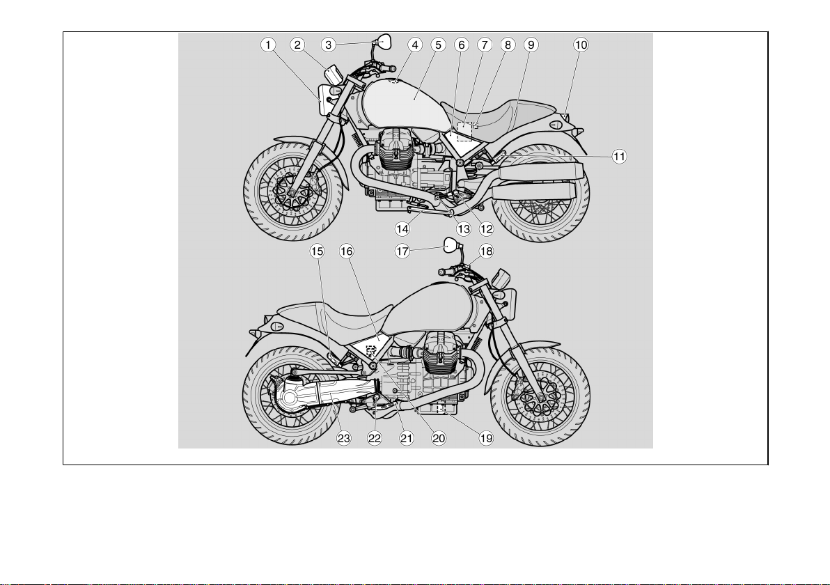
Ubicación componentes
principales (02_01)
Leyenda:
1. Faro delantero
2. Tablero de instrumentos
3. Espejo retrovisor izquierdo
4. Tapón del depósito de combustible
5. Depósito combustible
6. Carenado lateral izquierdo
7. Batería
8. Portafusibles principales
9. Asiento conductor/pasajero
10. Faro trasero
11. Estribo izquierdo pasajero
12. Estribo izquierdo del conductor
13. Palanca de mando del cambio
14. Caballete lateral
15. Estribo derecho pasajero
16. Carenado lateral derecho
17. Espejo retrovisor derecho
18. Depósito líquido freno delantero
19. Filtro aceite motor
20. Depósito de líquido del freno trasero
21. Palanca de mando del freno trasero
22. Estribo derecho conductor
23. Horquilla trasera monobrazo
Arrangement of the main
components (02_01)
Key:
1. Front headlamp
2. Instrument panel
3. Left rear-view mirror
4. Fuel tank cap
5. Fuel tank
6. Left side fairing
7. Battery
8. Main fuse box
9. Rider/passenger saddle
10. Rear light
11. Passenger left footrest
12. Rider left footrest
13. Gear shift lever
14. Side stand
15. Passenger right footrest
16. Right side fairing
17. Right rear-view mirror
18. Front brake fluid reservoir
19. Engine oil filter
20. Rear brake fluid reservoir
21. Rear brake control lever
22. Rider right footrest
23. Single arm fork
25
02_02
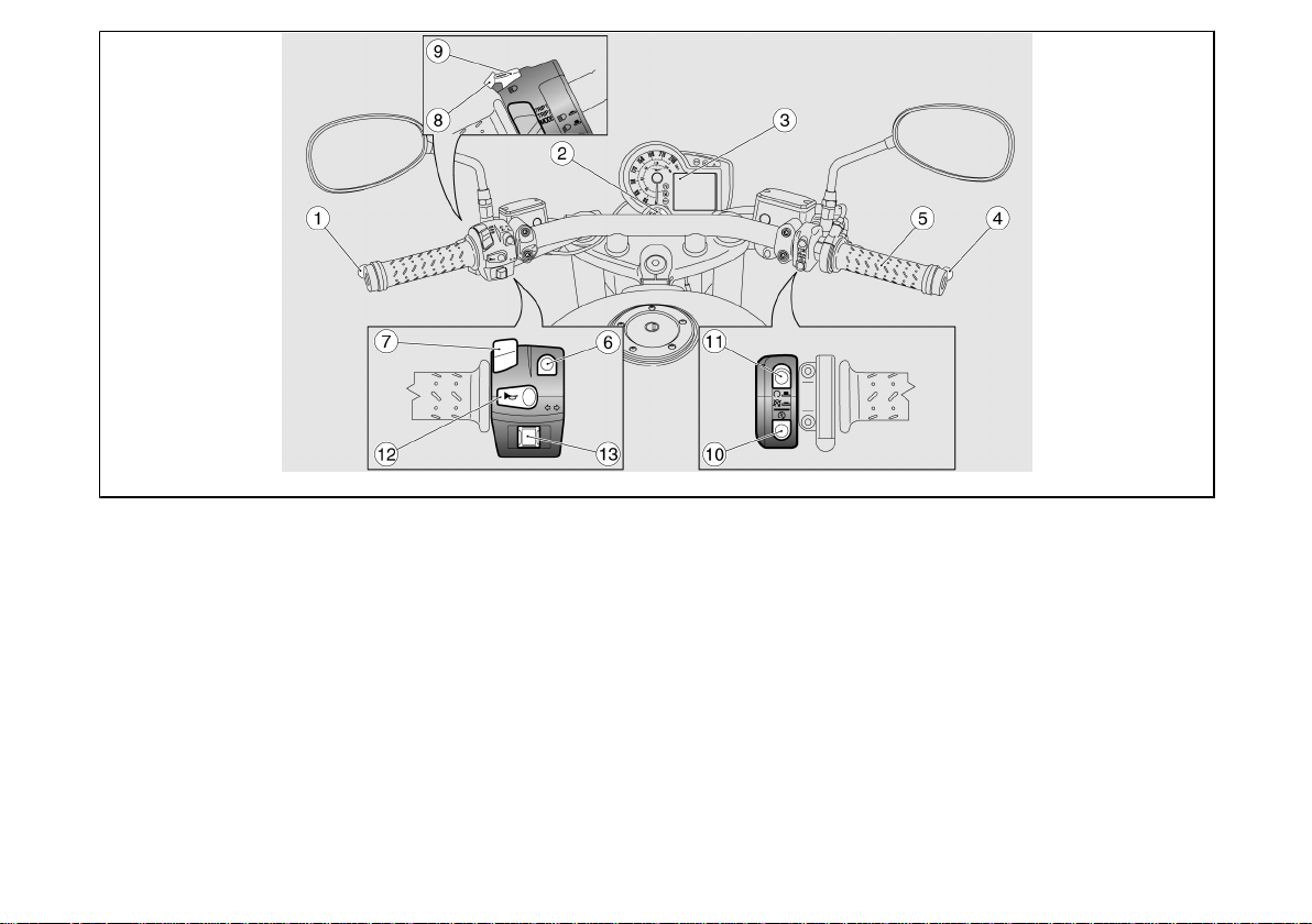
Tablero de instrumentos
(02_02)
Leyenda:
1. Palanca de mando embrague
2. Conmutador de arranque bloqueo
del manillar
3. Instrumentos e indicadores
4. Palanca del freno delantero
5. Puño del acelerador
6. Conmutador de luces
7. Selector de funciones Pantalla
8. Pulsador destello luz de carretera
9. Pulsador SET
26
Dashboard (02_02)
key:
1. Clutch control lever
2. Steering lock ignition switch
3. Instruments and gauges
4. Front brake lever
5. Throttle grip
6. Light switch
7. Display functions selector
8. High-beam flashing switch
9. SET button
10. Starter button
11. Engine stop button
12. Horn button
2 Vehìculo / 2 Vehicle
10. Pulsador de arranque
11. Pulsador de parada del motor
12. Pulsador claxon
13. Interruptor intermitentes
13. Turn indicator switch
02_03
02_04
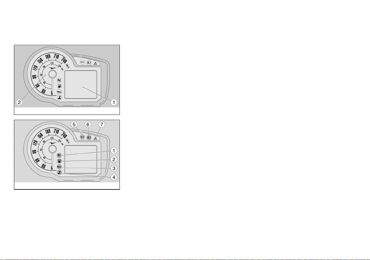
Conjunto de instrumentos
(02_03)
Leyenda:
1. Pantalla digital multifunción
2. Velocímetro (cuentakilómetros/
cuentamillas)
Grupo testigos (02_04)
Leyenda:
1. Testigo cambio en punto muerto
(color verde)
2. Testigo reserva del combustible
(color anaranjado)
3. Testigo de presión de aceite
motor (color rojo)
4. Testigo caballete lateral (color
amarillo)
5. Testigo intermitentes (color verde)
6. Testigo luz de carretera (color
azul)
7. Testigo recapitulativo de las
alarmas / activación immobilizer
- alarma (color rojo)
Instrument panel (02_03)
Key:
1. Multifunctional digital display
2. Speedometer (odometer in kilometres/ miles)
Light unit (02_04)
Key:
1. Gear in neutral warning light
(green)
2. Low fuel warning light (orange)
3. Engine oil pressure warning
light (red)
4. Side stand warning light (yellow)
5. Turn indicator warning light
(green)
6. High-beam warning light (blue)
7. Alarm summary warning light /
immobilizer activation - alarms
(red)
27

02_05
02_06
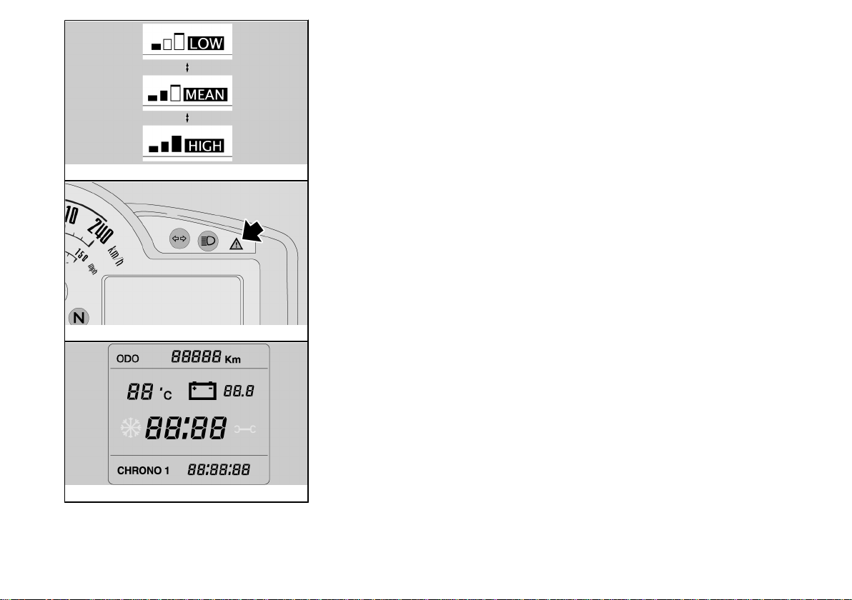
Representacion visual digital
por cristales liquidos (02_05)
Girando la llave de encendido a la posición ON, en la pantalla se encienden durante dos segundos:
- el logotipo
- todos los testigos
- la retroiluminación
Luego de dos segundos, todos los ins-
trumentos indicarán instantáneamente el
valor actual de las magnitudes medidas.
Las programaciones estándar que se visualizan en la pantalla son:
- ODÓMETRO (zona A)
- TEMPERATURA AMBIENTE (zona B)
- TENSIÓN BATERÍA (zona C)
- RELOJ (zona D)
- Ordenador de viaje y funciones complementarias (zona E)
Digital lcd display (02_05)
The following indicators will light up for a
couple of seconds on the instrument panel when the ignition key is set to "ON":
- the logo
- all warning lights
- the instrument panel backlighting
After two seconds, all instruments imme-
diately show the current value of the
measurements read.
The standard indications displayed are:
- ODOMETER (zone A)
- AMBIENT TEMPERATURE (zone B)
- BATTERY VOLTAGE (zone C)
- CLOCK (zone D)
- Trip computer and additional functions
(zone E)
02_07
Teclas de mando (02_06,
02_07, 02_08, 02_09)
1. Selector de tres posiciones:
TRIP1 / TRIP2 / MODE
2. Pulsador SET; con una presión
breve se recorren las distintas
funciones del MENÚ; con una
presión larga se confirma la selección.
28
Control buttons (02_06, 02_07,
02_08, 02_09)
1. Three position selector switch:
TRIP1 / TRIP2 / MODE
2. SET button; pressing briefly
calls up the function selection in
the internal menu, holding the
button down confirms the selection.
2 Vehìculo / 2 Vehicle
02_08
02_09
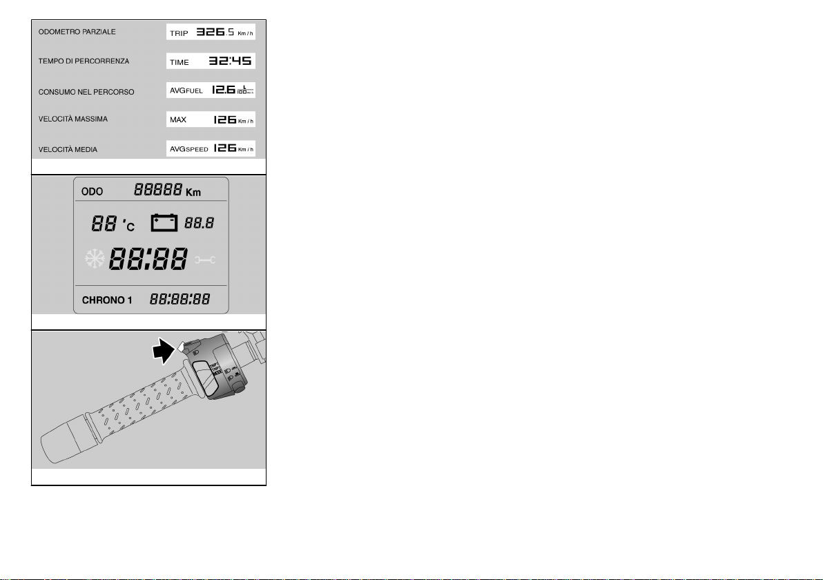
TRIP 1 Y 2
En las configuraciones TRIP1 y 2 se
muestran los datos correspondientes a
los parciales de viaje 1 y 2.
La indicación del parcial visualizado se
muestra en el ángulo inferior derecho.
Para seleccionar las configuraciones
TRIP 1 o TRIP 2: Colocar el selector (1)
en la posición correspondiente a la configuración TRIP que quiera visualizarse.
En la zona inferior (E) de la pantalla, se
visualizan las siguientes cantidades:
- ODÓMETRO PARCIAL
- TIEMPO DE RECORRIDO
- CONSUMO DURANTE EL RECORRIDO
- VELOCIDAD MÁXIMA
- VELOCIDAD MEDIA
El cambio entre una magnitud y la suce-
siva se realiza presionando brevemente
el pulsador SET (2). Para poner a cero
todas las magnitudes parciales del TRIP
seleccionado, presionar prolongadamente el pulsador SET (2).
TRIP 1 AND 2
Data related to trip distances 1 and 2 are
displayed at the TRIP1 and 2 configurations.
The trip odometer displayed is viewed at
the bottom right angle.
To select TRIP 1 or TRIP 2 configuration:
Move the selector (1) to the position corresponding to the TRIP configuration you
wish to display.
The following values are viewed at the
bottom zone (E) of the display:
- TRIP ODOMETER
- TRAVELLING TIME
- TRIP CONSUMPTION
- MAXIMUM SPEED
- MEAN SPEED
To shift from one value to the next, press
the SET button (2) briefly. To reset all trip
values of the TRIP selected, push and
hold the SET button (2).
02_10
- MODE
La configuración MODE reúne las funciones que permiten que el usuario interactúe con el sistema.
29
MODE
The MODE configuration includes the
functions that allow the user to interact
with the system.
02_11
Para seleccionar la configuración MODE,
colocar el selector (1) en la posición MODE. En la zona inferior (E) de la pantalla,
cada vez que se presiona el pulsador
SET (2), se visualizan cíclicamente las
siguientes cantidades:
- CONSUMO INSTANTÁNEO
- CRONÓMETRO
- MENÚ (función excluida con vehículo
en movimiento)
La función CONSUMO INSTANTÁNEO
no permite interacciones con el usuario.
To select the MODE configuration, set
the selector (1) to MODE. The following
values are viewed cyclically at the bottom
zone (E) of the display each time the SET
button (2) is pushed:
- CURRENT CONSUMPTION;
- CHRONOMETER
- MENU (function disabled when riding)
The CURRENT CONSUMPTION func-
tion does not admit interaction with the
user.
02_12
02_13
CRONÓMETRO
Para utilizar el cronómetro, desde la configuración MODE, presionando brevemente il pulsador SET (2), seleccionar la
función CRONÓMETRO. En la zona inferior de la pantalla se visualiza el mensaje CHRONO y al lado el número de la
última medición realizada y el dato medido.
Presionando brevemente el pulsador
SET (2), el cronómetro comienza a registrar una nueva sesión. Presionando
nuevamente el pulsador SET (2) antes
de los diez segundos del inicio, la medición se anula y comienza una nueva medición.
Presionando nuevamente el pulsador
SET (2) diez segundos después del inicio, la medición se interrumpe, se memoriza y comienza una nueva medición.
30
CHRONOMETER
In order to use the chronometer, from
MODE setting, press the SET button (2)
briefly and select the CHRONOMETER
function. The bottom zone of the display
shows the word CHRONO next to the
number of the last measurement and the
value registered.
After pressing the SET button (2) briefly,
the chronometer starts to time again.
Press the SET button (2) again within ten
seconds of the start to cancel the timing
operation and to begin a new measurement.
Press the SET button (2) again after ten
seconds of the start to stop timing, store
the time and begin a new measurement.
The series of measurements is interrupted by pressing and holding down the
SET button (2).
 Loading...