

MOTO GUZZI 850-T5 Owner's Manual
•
,-'
OWNER'S
MANUAL
'"'"
............
....:I
-"1pIIof ..... !hie
__
..
InctIe.u.. only
otnd
Itw
~
_
ItMII
!hi
"0/'1110
~
.......
~
......
-..
_,.,
10<
bItn.
~
01'
10<
_trvctI'«e
or
__
~I_
..
~
.......
n<IIIw
.
SE
IMM
MOTO
GUZZI
5 P A
.•
T~
~
.
CotII
28110
00
01
Pron-.:I
..
bIy
0 E
ca
~
700
10
&:I
Dear rider
First
of
all we wish to thank you
for
choosing this motorcycle
of
our production.
By following
the
instructions outlined in this manual you will ensure your
bike
a long
and
troUblefree
life.
Before riding, please read thoroughly this manual in order
to
know your
motorcycle's features and how
to
operate it safely.
All major checking and overhaul jobs are best carried out by our dealers
who
have the necessary
fac/HUes
to
quickly and competently repair your
Moto Guzzi.
Repairs
or
adjustments by any other than a Guzzi dealer dunng the war-
ranty period could invalidate
the
warranty right.
INDEX
•
Main features
9 ldentiflCallon
data
10 Controls and accessories
12 Instruments and OOfltrols
20
Aklmg
Instructions
22
Aunlling
in
23
Maintenance
and
adjustments
31
Removal
01
wheels
34
Service schedule
36
Lubrications
..
Carburatlon
43 Valve gearing
..
I
gnition
47
Electrical equipment
53 Conversion table
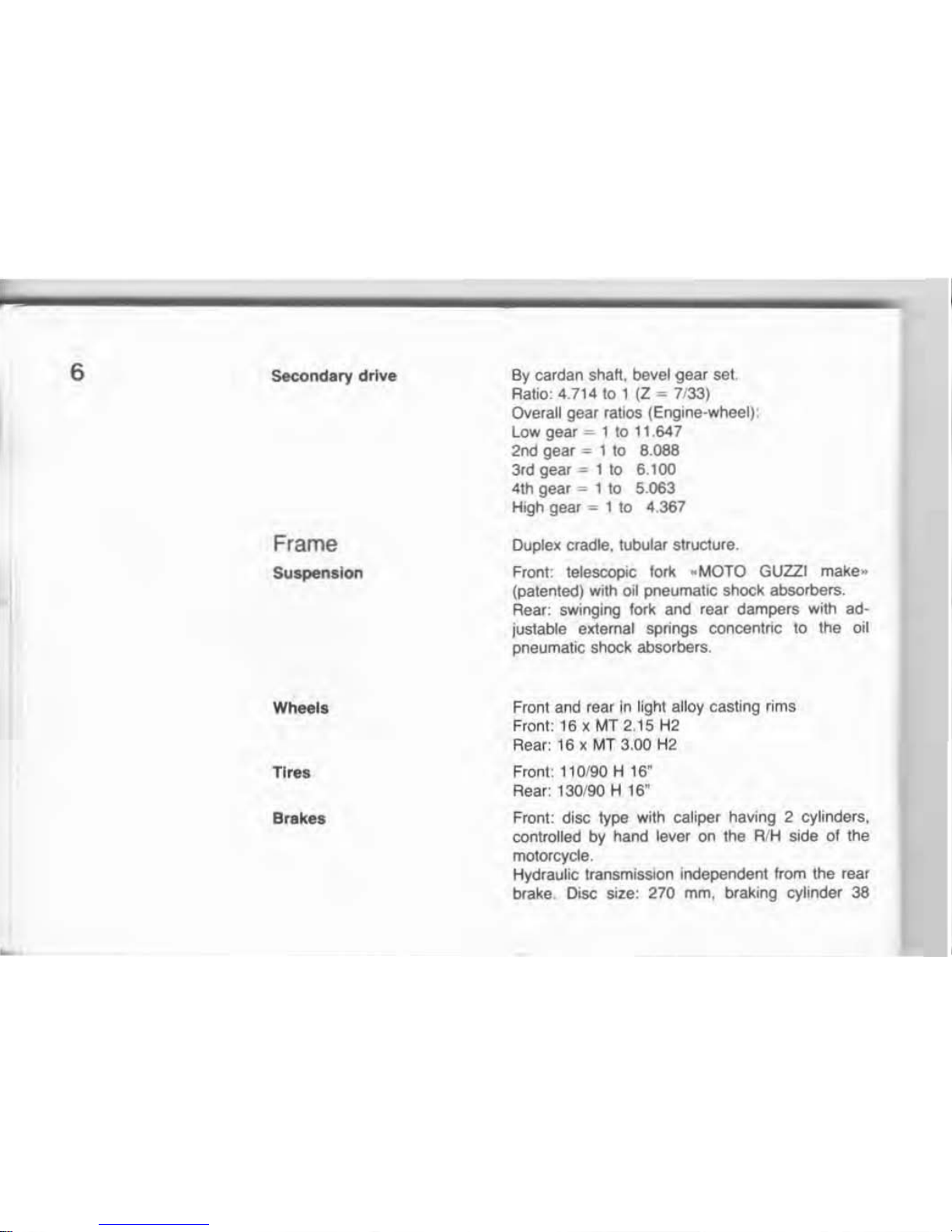
6 Seco
ndary drive
Frame
Suspension
Wheels
Tlr.s
Brakes
By cardan shaft, bevel
gear
sel
Ratio; 4.71410 1 (Z '"' 7133)
Overall gear ratios (Engine-wheel) .
lowgear
""-
110 11.647
2nd
gear='
1
10
8.088
3rd
gear
= 1
to
6.100
4th gear =-1
to
5.
063
High gear
""'
1
10
4.367
Duplex cradle, tubular structure .
Front: telescopic
fork
..
MOTO GUZZI make"
(patented) with 011 pneumatic shock absorbers.
Rear: swinging lork and rear dampers with ad-
justable elrtemat spnngs concentric
10
Ihe oil
pneumatic shock absorbers,
Front and rear
In
light alloy casting rims
F
ron
t: 16)(
MT2.15
H2
Rear: 16
Ie
MT
3.00 H2
Front: 110190 H 16"
Rear: 130190 H 16
"
Front : disc type with caliper having 2 cylinder
s,
coolrolled
by
hand lever on the R/H side
01
the
motorcycle
.
Hydraulic transmission independent from the tear
brake. Disc size: 270 mm, braking cylinder 38
,
Dimensions
end
weights
Performances
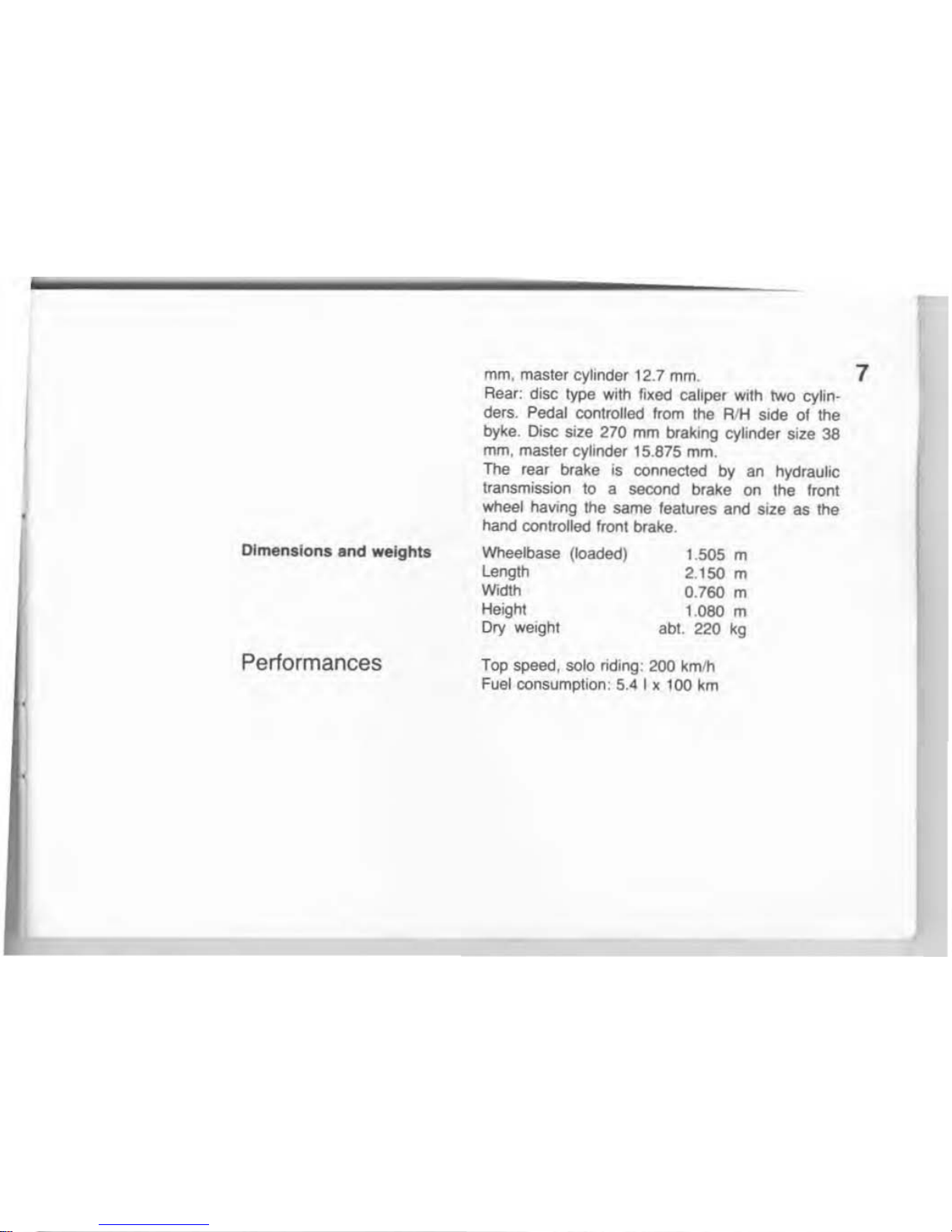
mm
, master cylinder
12
.7
mm
. 7
Rear: disc type
with
fixed caliper with
two
cylin-
ders. Pedal controlled from the RIH side
01
the
byke. Disc size
270
mm braking cylinder size 38
mm
, master cylinder 15.875 mm.
The rear brake is
connec1ed
by
an
hydraul
IC
transmission to a
secood
brake on the Iront
wheel haVing the same features and
Size
as the
hand controlled front brake .
Wheel
base
(loaded)
leogth
Width
Height
Dry weight
1.
505
m
2.150 m
0.760 m
1.080 m
abl. 220
kg
Top
speed
, solo nding: 200 kmlh
Fuel consumption: 5.4 I x 100 km
8
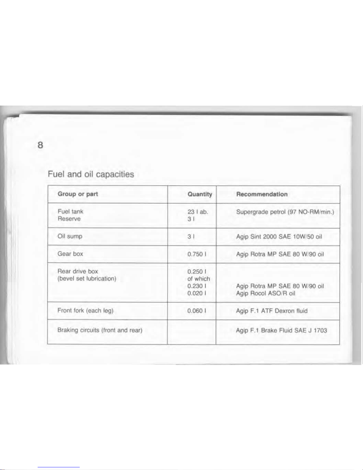
Fuel and oil capacities
Group
or
part
Quant
ity
Recommendation
Fuel
lank
231
abo
Supergrade petrol (97 NO-AM/min.)
Reserve
31
Oil
sump
31
Aglp Sin! 2000 SAE tOW/50
011
Gear
box
0.
750
I Agip Rotra MP SAE
60
WI90 oil
Rear drive bol(
0.250 I
(bevel set lubrication)
of which
0.230 I Aglp Rolra MP SAE
80
W/90 oil
O.
O2()
I
Agip Rocol ASOIR oil
Front
fori<
(each leg)
0.060 I Agip
F.1
ATF Dexron lIuid
Braking circuits
(IrOnl and rear) Agip F.l Brake FlUid SAE J 1703
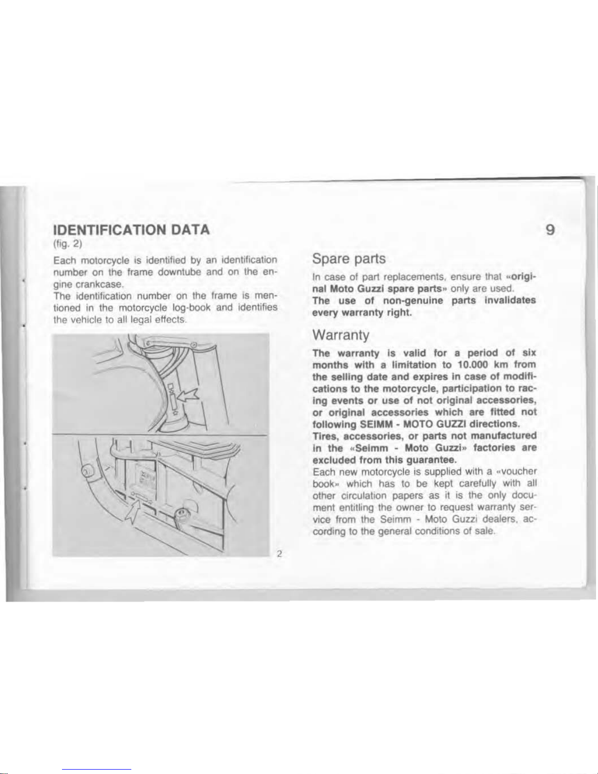
IDENTIFICATION
DATA
('~.
2)
Each motorcycle
Is
identified
by
an identification
number on the ftame downlube and
on
the en-
gine
crankcase.
The Identification number
on
the frame
IS
men·
tloned
in
the motorcycle log-book and identities
the vehicle to all legal effects
,
Spare parts
In case
01
pan replacements, ensure thaI
..
origi-
nal Moto
Gual
spare parts " only are used.
The use
of
non-genuine parts Invalidates
every warranty right .
warranty
The warranty III valid for a period
01 six
monlhs
with.
limitation
to
10.000 km from
the
seiling
date and expires In case
01
modltt-
cations to the motorcycle, participation
to
rac-
Ing
flvents or use of not original
acc.,sorie.,
or
origlna' accessories which are
fitted
not
following SEIMM
- MOTO GUZZI directions.
Tires, accessories,
or
parts
not
manufactured
In
the
_Selmm - Moto
Gunl
..
factorl
••
are
excluded
from
this
guarantee.
Each
new
motorcycle is supplied with a
~
voucher
book~
which
has
10
be kept carefully wilh all
other
C1rculatlon
papers as
it
;s the
only
docu-
ment
entll~ng
the owner
10
request warranty ser-
vice
from the Selmm - Mota
GUZZI
dealers. ac-
COtding
to the general condibons of sale
t"
9
,
10
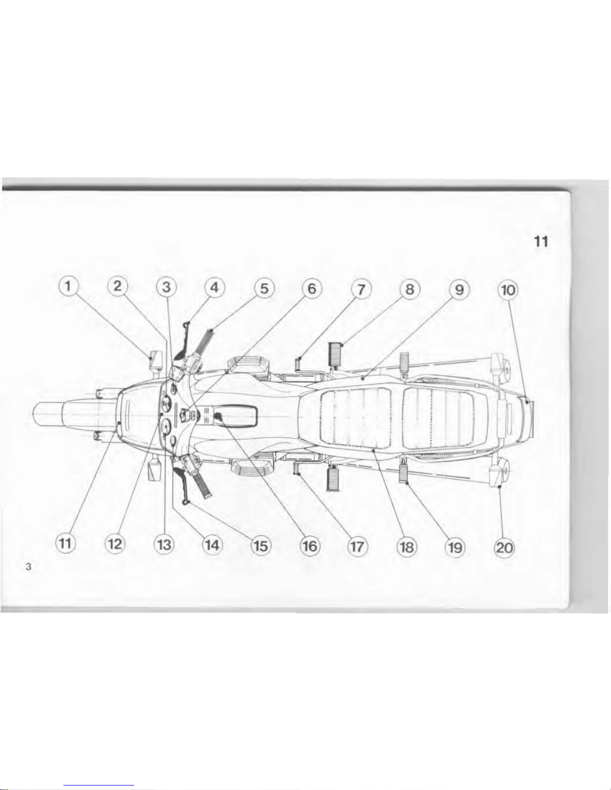
CONTROLS AND ACCESSORIES
(fig. 3)
1 Front
tum
light signals
2 Speedometer
3
Voltmeter
•
Atght front brake control lever
5 Throl1le control grip
•
Ignition key
7
lett
Ironl brake and
reaf
brake pedal
8 Front footrest
•
Master cylinder, lett front brake and rea r
brake
,.
Taillight
11
Headlight
12 Panel board
13
Rev-counter
1.
Watch
15
ClutCh le\Ier
,.
Lock
sel,
fuel cap opening
17 Gearshift pedal
18 Saddle release lack
,.
Footrest, pillioo
20 Rear
tum
signallrghls
..
Right_ or "'
eft" In
the texi are intended as seen
by
the rider astride the motorcycle .
11
3
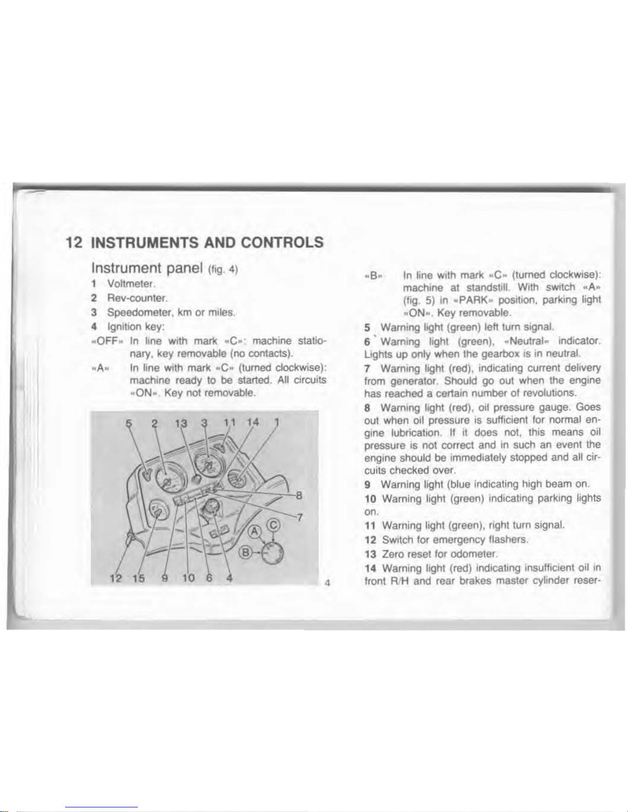
12 INSTRUMENTS AND CONTROLS
Instrument panel
(fig.')
1 Vohmeler.
2 Rev-counler.
3 Speedometer,
km
or miles.
.. Ignition
key :
•
OFF
~
In
line with
mar1<
..
e
.:
machine statio-
nary. kay removable (no contacts) .
..
A.
In
tine
with mark
..
C- (turned clockwise):
machine ready
10
be started.
AU
circuits
..
ON- Key not removable.
.. 8..
In
line
With
mark
..
C- (turned clockwise):
machine al
staoostJll.
With
sWItch
"A"
(flQ
5)
In
..
PARK- position,
par1<lng
light
..
ON-. Key removable.
5 Warning light (green) left turn Signal
6 ' Warning light (green
).
-Neutral-
IndiCalOf
.
lights
up only when the gearbox is In neutral.
7 Warning light (red), Indicating current delivery
from generator.
ShOUld
go oul when the engine
has reached a certain number
01
revolutions .
8 Warning light (red), oil pressure gauge. Goes
out when
011
pressure
IS
sufficient
for
normal en-
gine lubricatIOn.
If
it does not, this means oil
pressure
IS
not correct and In
such
an event the
engine
should be Immediately stopped and all circuits checked over.
9 Warning tight (blue
indicating high beam on.
10 Warning light (green) indicating parking lights
0'
.
11
Waming light (green), right turn signal.
12
SWltctllor emergency tlashers.
13
Zero reset for odometer.
14 Warning
light (red) Indicating Insufficient oil
In
4 lront AIH and rear brakes master cylinder reser-
VOir
,
When il lights up
It
IS necessary
10
reslore the
correct
flu
id level and to check tor possible Iluid
leak
s.
15 Quartz watch: lor its adjustment poSh
and
tum central knob.
5
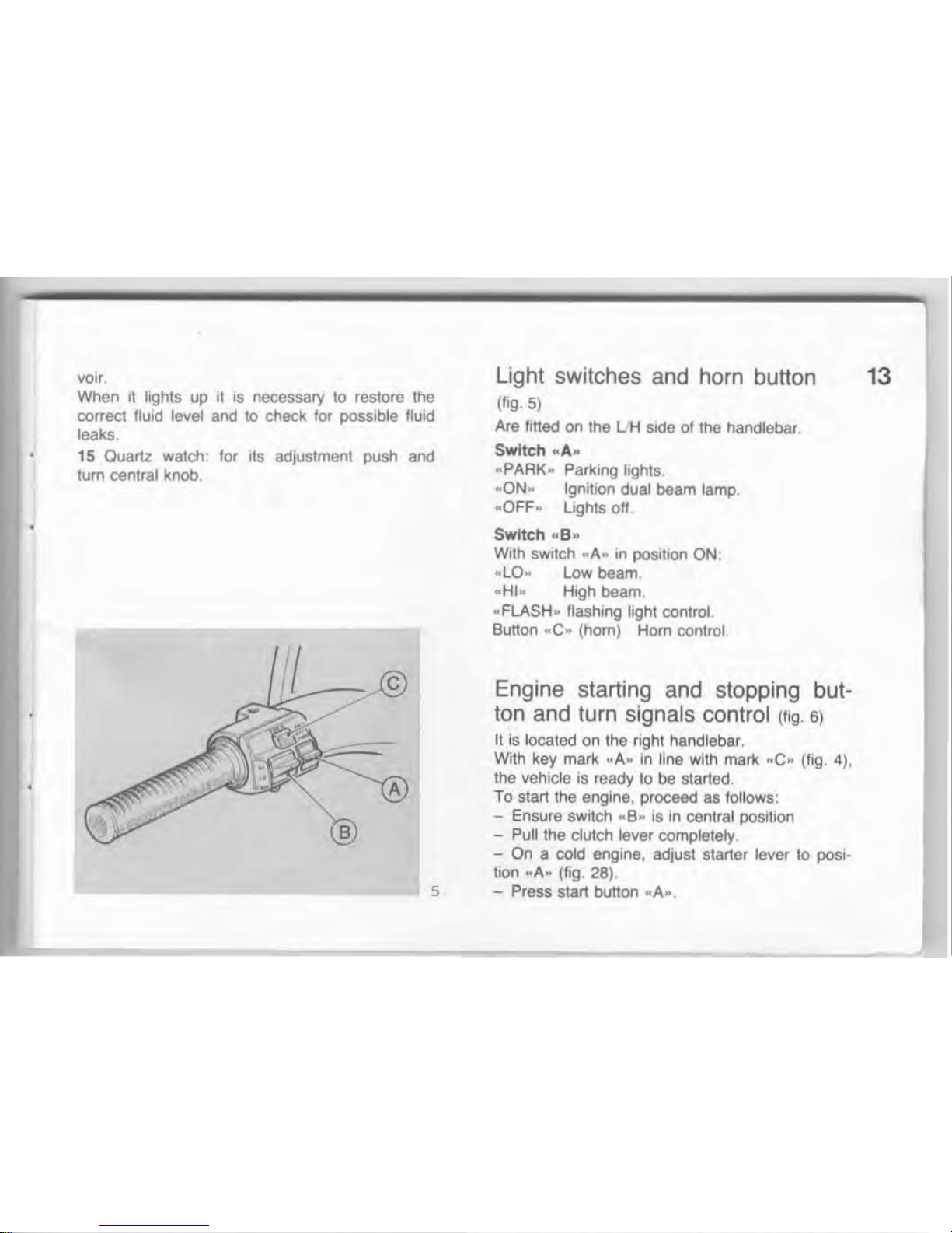
light
sw
itches a
nd
horn button
(lIg.
5)
Are titled
on
Ihe
UH
side of the handlebar.
Switch "A.
..
PARK. Parking lights.
..QN~
Ignition dual beam lamp .
..
OFF
,.
lights
off
Switch
.. S ..
With sWllch
.. A ..
In
positIOn
ON
:
.. lO..
low
beam
..
HI
~
High beam.
" FLASH
..
flashing light control.
Button
..
e
..
(hom)
Hom
control
Engine starting
and
stopping but·
ton and turn signals control (Iig.
6)
It is located on the right handlabar.
Wilh key mark
~A"
In
line with
man.:
~C
~
(fig. 4),
the vehicle is ready to be started.
To start
the angine, proceed
as lollows:
- Ensure switch " B
..
is
in central position
-
Pull the
dutch
lever completely.
- On a cold engine, adjust starter lever to posi.
tion
..
A
..
(fig. 28).
- Press start button
.. A ...
13
14
To
stop the engine operate on the Ignition switch
on
the panel.
To
stop the engine in an emergency:
- Move switch "e· up or down.
As soon
as
the engine stops,
tum
ignition key
(fig
. 4) COUnlerclockwise
till
mar\(
..
OFF.
is
in
tine
with
man<
..
C". and take
out
the key
from
the
k>ckset
.
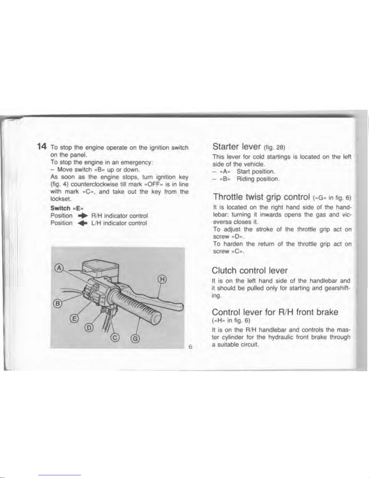
Sw
itch ..
E"
Position
...
RIH indICator
control
PosrtJon
• UH indicator control
6
Starter lever (fig. 28)
thIS
lever for cold startings is located on the
teft
side
01
the vehicle.
-
.. A..
Start positioo .
- "B.. Riding posihon.
Throttle twist grip control I-G- '"
f~
.
6)
It
is located on
the
right hand
SIde
or the hand-
lebar:
turning it inwards opens the gas and vic-
eversa
Closes
it.
To adjust the
strOke
of Ihe throttle grip aci
on
screw
..
0 ...
To harden the return of the throttle gnp act
on
screw
..
C ...
Clutch control lever
It
is
on the left hand side of the handlebar
and
It
should
be
pulled only
for
starting and gearshift-
ing.
Control lever for RlH front brake
(
.. H ..
in
fig. 6)
It
is
on the R1H handlebar and controls the mas·
ter cylinder tor the hydraulic front brake through
a suitable clfcuit.
Left front
and
rear brake control
pedal
(~F~
in
lig. 18)
II
15
centrally located on the
A1H
side of the vehI-
cle and it is link connected to the master cylinder.
II
controls the
lett
froot brake and rear brake
simultaneously.
7
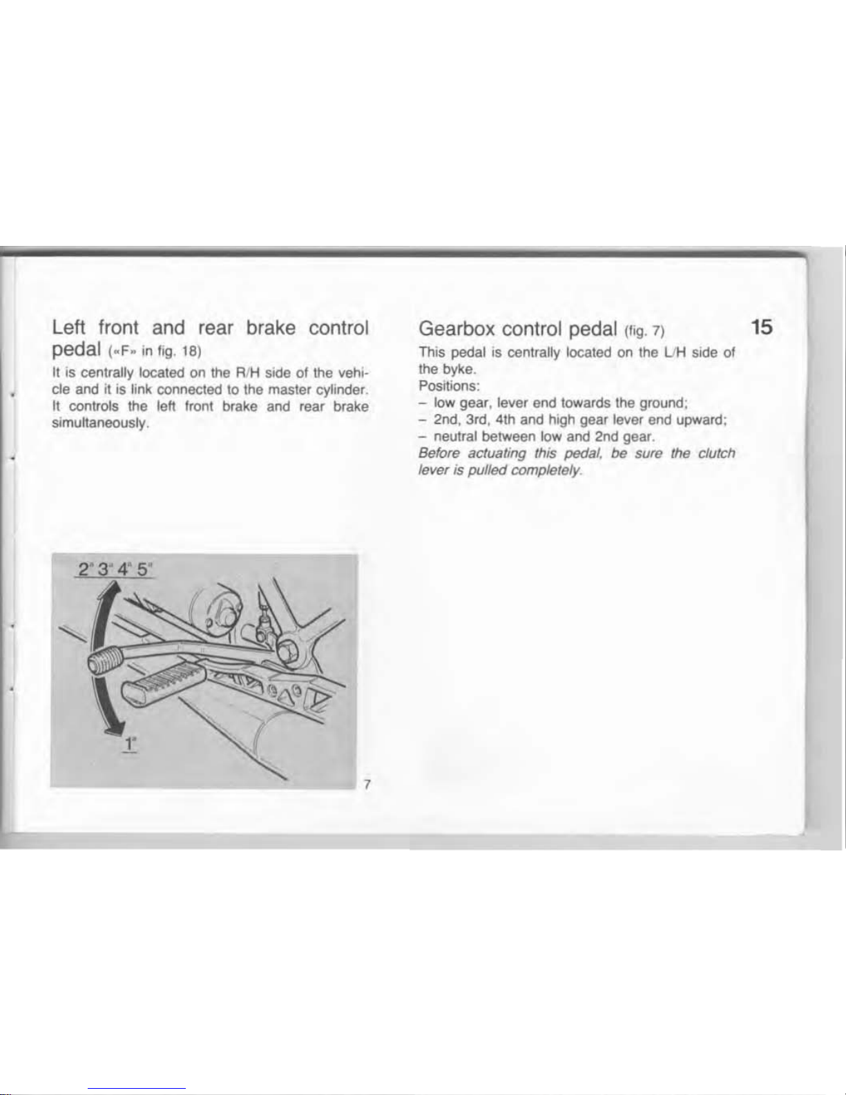
Gearbox control pedal If;9. 7) 15
This pedal is centrally lOcated on the
UH
side of
the byke .
Positions:
-
low
gear, lever end towards the ground;
- 2nd, 3rd, 4th and high gear lever end upward;
- neutral between
low
and 2nd gear.
Before actuating this pedal,
be
sure
the
clutch
lever is pulled completely.

16
Fuel
filler cap
lfig
.
BI
To acceed to hiler
cap
..
B
~
rt
IS
necessary to tum
key
.. A ..
clockwise on the protecllon cover, then
the
cover
.. e ..
can
be
raised
.
N.B. Fuel overflows during fuel filling have
10
be
eliminated
al
once
to
avoid damages to the tank
pamt.
B
9
Fuel taps
llog.
91
Are fined under the tank , rear side.
The
luellap
has 3 poSitions :
..ON..
Open. lever arrow upward
s.
..
RES
..
Reserve, lever arrow downwards.
..
OFF
- Closed, arrow on lever horizontal.
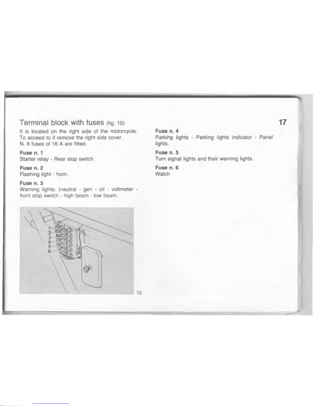
Terminal block with fuses (';g. 10)
II
is
located on the right side of the motorcycle.
To acceed
10
it
remove the right side cover .
N. 6 fuses 0116 A are titled.
Fuse n. 1
Starter relay · Rear Slop
sWItch
.
FUM n. 2
Flashing l
ight·
hom
.
Fuse
n. 3
Warning
lights: (neutral -
gen
- oil - voltmeter •
Irool
stop SWitch · hi
gh
beam -
low
beam
.
Fuse
n. 4
Parking lights - Parking lights indicator - Panel
lights.
Fuse
n. 5
T
um
signal lights and their warning lights.
Fuse
n. 6
Watch
17
 Loading...